

Page 1
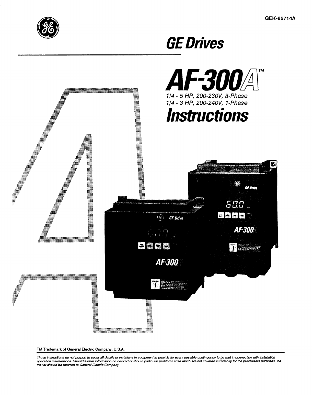
GE Drives
l/4 - 5 HP, 200.23OV’ 3-Phase
l/4 - 3 HP, 200=24OV, I-Phase
lnsbuctions
GEK-85714A
.:~~~~.~-~~~:*~-~~*~~-~~-~~~. . . . . . ,.\ 2.
***.*.*.*.* cs’~.:‘~~.“~‘~‘.~.~.-.~.-.-.-.-*~.-. i.5. . . .*a pg.* .*.*.*.*.*. >*.>; .*.*.*.*.*.*.*.*.*.*.*. 3
..,~-~,-:;~~~~~~~~~-:~~:~~~~~-.~.~ . . . ..A -
. * . . . . . . . . . . . . . . . . . . . . . . . ,.~.*.*.*.*.*.~.~.~,.*.~.~ *.* *.*.*.*.*. >:.:.: .*.*.*.*.~.‘.*.~.*.*” *.*.* *.*. . .*.*.*.* .‘.*.‘.‘.*.*.~.*.*.*.*
.-~:~.~~~:~~.~:.;.~i.: ~~~~~~~I-~~~~~~~-~s;~.;;;;.~.is;~.--~;~.~.;-.~-.~~~~-~.-.-.~-.~.-.-.~~~~~~-~~~~~~~~~~~~~~~~~~
. . . . . .
.;.:.:.:.-~.
..-...
:: .': -----
:*;.:.:.3:.:
7...-.-.:-
. . . . . .
:yy:y$.*
-.-:.-.'.'.'
>.-.-2...*.
<+:.:.:.:.*
. . . . . . .
.~.-.-~-.-.-.-
,....
.- -m-.-.*.-T-
.,..., . . - .% .
.:;;i;.:.:.
>:.:.>>c.
.-.;.ym+..*<*.*
zg?
>y*.
.-+'
.-:
z:*
‘.~.-.-.-.i~.’ ‘...-~:~~~*~~~:!~~~~:.~~~~~~~~?~~,,,~~~~~,~~..s~~~.~.~:~
. - -
~-.-~,-~0~-~~~~~~~~s~~~:-~~~~~~~~s
y. +* .‘:,s\ .‘.....f.......
. . . . . . . . . . . .*
y<ya
-~:y~*-i
y&y..*
A4
<.-;.>; a-i- - -A
-A-s'\
x.:<<<.
<<.-.:.x
-:.:&-.:.
:.:.:+:.s
+x-x
-.-'-.-.-.\
l . . .*.f.
TM Trademark of General Electric Company, U.S.A.
Those kWucbbns do not purport to cw6f ail details of vafiatims in equipment to
cqxxatbn maintenance. Should tbrtbinformatian be desked or should pariicuku problems
rnatw should be reloned to Gene& Electric Cotnpmy
\
.y.:.;.;.;<
-.-.a-.-.-.
il;&$A
>Sk’.\
.-.,-&-.
-A.:.:*
.y.:.:.:.:
-.-.-.a-.-‘;
‘$g$
. .-‘a-. .
:;y::::;:
. . . . .
yy’p
p:.->
-3
.*.:.y.:.:
.-.-.-.-.a
m
,v-:-s
x.:::>;::
.y’y.:<
-.-.a-.-.,
-b.x.-.:.
>-2-3. .*...,..‘..,....
.-z-h*?.-.-.-‘-.-,.-. .~.~..-.-A->.- - * --’ - - - -’ -.-.-.-.‘.-.-.~-.~.-.-.-.-.-.-.-.-.-.~.-.-.-.-.~.~.-.-.-:.-.~.~~
**~*~*~*~~~*~,*~*~,*~~~*,*,*~*~.~~~~*’~~’~~~~:~:‘:~~‘~‘*~* **~~*~~~*~S~*~~S~~*~**.i~.~*~-~~~~~~~~~~~~~~~~
,..... s,.rr,,~r.,,~;.:.:;~.:=-’ ’ -.-t.- * - -.- - *.-.- * - ‘t a.*.-:.* *. .
b
‘. .-.-.-.y -~.-.-.-.-.-.-.-.-.-.~.-.-.,:.:~.:.:.:.:.:.:.:,:.~.:.:.-.:.:.-
.\-‘i-.-. 8~~8~-.~8-.~--~-.-.~- - - -
. . . . . . . . . . . . . . . . . . . . . 1.. . . . . . . . . . . .\-...-.-a
..,~..*~rh,*~S.‘.....~...‘,........ -.
. . , . . . . . . . . . . . . . . . .-. . . .
x-xc-i
.:.::.;.:.:
:.:.:.:...:.
;<:.p-4
:.:.:.:.:.:.
.-.-.-:.-.-
. . . . . .
. . . . . .
. . . . . .
. . . f . .
-... :.:.~.~.:.:~.‘.:.:.:.:-:.:.:.:.:.:.:.:,
. . . . . . . .-. , . . . . . . . . . . .
provide
for overypossibk, cmtingcncy to be met in
ark?
M&h are ruM covered suffkientiy foe the purchasers purposes, the
cowwction with
instaM.bn
Page 2

Page 3
/ f
f
@ .
GE Drive Systems
SUPPLEMENT #l
FOR INSTRUCTION MANUAL GEK-85714A
These instructions do not purport to cover all details or variations in equipment, nor to provide for every possible contingency to be met
during installation, operation, and maintenance. Should &rther information be desired or should particular problems arise that are not
covered suficiently for the purchaser’s purpose, the matter should be referred to GE Drive Systems, Salem, Virginia U.S.A.
This supplement contains additional information
needed when installing and operating the AF-300A
series of inverters. Refer to the information of this
supplement in addition to that contained in GEK85714A for the figures, tables, and paragraphs listed in
this supplement.
Table 3: Application of Wiring and Equipment
The recommended wire sizes shown in Table 3 are
minimum sizes. Due to variations in installation,
check that the recommended wire sizes are adequate
for that particular installation. All inverter installations must meet the applicable national (NEC, CEC)
and local electrical codes. It is the system engineer’s
responsibility to be certain that the inverter installation complies with all applicable electrical codes. (If a
system engineer is not involved, it is the user’s responsibility.) Only adequately trained persons should
install any programmable inverter.
Figure 4-6. Basic Connection Diagram
The 3-phase AC circuit breaker shown in this figure is
incorrectly illustrated as three breakers. It is actually a
single, 3-pole breaker.
Figure 4-6. Basic Connection Diagram
Figures 8-4 and 8-5. Control Block Diagrams
Thermal Relay shown in theses figures is not a standard option kit available from General Electric Drive
Systems. Overload protection is not provided by the
AF-300A and therefore must be provided by the user.
(Typical thermal relay circuit wiring is shown in Figure
4-6.) All inverter installations must meet the applicable national (NEC, CEC) and local electrical codes.
It is the system engineer’s responsibility to be certain
that the inverter installation complies with all applicable electrical codes. (If a system engineer is not
involved, it is the user’s responsibility.)
Table 10: AC Line Fuses and Fuseholders
Due to variations in installation when mounting fuseholders and fuses external to the inverter, check that
the recommended fuse sizes are correct for that
particular installation. When using the recommended
fuse sizes, overload protection must be provided by the
user in order to comply with most electrical codes. All
inverter installations must meet the applicable national (NEC, CEC) and local electrical codes. It is the
system engineer’s responsibility to be certain that the
inverter installation complies with all applicable
electrical codes. (If a system engineer is not involved,
it is the user’s responsibility.)
(10/14/94)
Page 1 of 1
Page 4

Page 5
AF-300A
Inverter
l/4
l/4
to 5 He 200-230\(, 3-Phase
to 3 HP, 200=24OV, 1 -Phase
GEK-85714A
Issue Date: August 1994
These instructions do not purport to cover all details or variations in equipment, nor to provide for
every possible contingency to be met during installation, operation, and maintenance. Should further
information be desired or should particular problems arise that not covered sufficiently for the purchaser’s purpose, the matter should be referred to GE Drive Systems, Salem, Virginia, U.S.A.
This document contains proprietary information of General Electric Company, U.S.A. and is furnished
to its customers solely to assist that customer in the installation, testing, and/or maintenance of the
equipment described. This document shall not be reproduced in whole or in part nor shall its contents be disclosed to any third party without the written approval of GE Drive Systems, 1501 Roanoke
Boulevard, Salem, Virginia 24153, U.S.A.
Page 6

Copyright 1994 by General Electric Company, U.S.A.
All
rights reserved.
Printed in the United States of America.
Page 7
TABLE OF CONTENTS
AF-300A
lnverters GEK-85714
Section
1 .
2 .
3.
4.
5.
Title
. . . . . . . . . . . . . . . . . . . . . . . . . . . . . . . . . . . . . . .
SAFETY PRECAUTIONS . . . . . . . . . . . . . . . . . . . . . . .
DESCRIPTION, COMPONENT IDENTIF
AND SPECIFICATIONS
General Description
Inspection items Upon Delivery
TABLE 1: AF-300A lnverter Standard Specifications
lnverter Options
INSTALLATION GUIDELINES
Installation Environment
Installation Mounting Clearance
Dimensions Chart:
WIRING PROCEDURES
Remove Terminal Block Cover
Main Circuit Wiring ..................................................................................
Control Circuit Wiring
Optional External Dynamic Braking Resistor Unit Wiring
TABLE 2: Terminal Identification/Function
TABLE 3: Application of Wiring and Equipment
INVERTER OPERATION
Pre-Operation Inspection
Selection of Operating Method
Function Code and Data Setting Procedures
TABLE 4: Operating Methods
Control Circuit Connection and Operation
Multi-Step Operations
TABLE 5: Function Code Settings*
........................................................................
................................................................................
. . . . . . . . . . . . . . . . . . . . . . . ..*............................................................ 2-7
.............................................................. 3-l
........................................................................ 3-1
..................................................................................
......................................................................
............................................................................
......................................................................
......................................................................
............................................................................
. . . . . . . .
ICAT ‘ION,
............................................................
. . . . . . . . . . . . . . . . . . . . . . . . . . 2-4
............................................................
..............................................................
.......................................... 4-l 0
.................................. 4-l 2
..............................................................
......................................
.............................................................. 5-l
.......................................... 5-4
......................................................
Paae
w
11
2-l
2-1
2-1
3-l
3-2
4-1
4-l
4-l
4-l
.................... 4-8
5-l
5-l
5-l
5-l
5-7
5-9
6 .
7.
*A duplicate of this table
FUNCTION CODE DESCRIPTIONS
TABLE 6: Function Code Descriptions
MAINTENANCE AND INSPECTION
Megger Test
Periodic Parts Replacement
Inspection Items
Measurement Points and Meters
with is also furnished in the back of this instruction (pp. Function Changes I-
2) to record field changes to
............................................................................................
..................................................................
......................................................................................
..........................................................
factory Function Code settings.
....................................................
................................................
....................................................
m
61
6-l
7-l
7-l
7-l
7-l
7-2
Page 8
AF300A /metiers GEK-85714
TABLE OF CONTENTS
Section
8. TROUBLESHOOTING
9 .
10. PARTS REPLACEMENT
Table #
Title
TABLE 7: Fautt Condition Description and Operation ........................
TABLE 8: Fault Condition Display and Corrective Action ....................
WARRANTY PARTS AND SERVICE 91
Warranty Coverage ................................................................................ 9-l
Out-Of-Warranty Procedures .................................................................. 9-l
Motors
TABLE 9:
lnverter Renewal Parts . . . . . . . . . . . . . . . . . . . . . . . . . . . . . . . . . . . . . . . . . . . . . . . . . . . . . . . . . . . . . . . . . . . . . . . . . . . . 10-l
TABLE
and Fuseholders . . . . . . . . . . . . . . . . . . . . . . . . . . . . . . . . . . . . . . . . . . . . . . . . . . . . . . . . . . . . . . . . . . . . . . . . . . . . . . . . . . . . . .
...................................................................................................... 9-l
10: AF-300A (200.23OV, 3-Phase) Line Fuses
Title Pagg
.......................................................................... 81
....................................................
. . . . . . . . . . . . . . . . . . . . . . . . . . . . . . . . . . . . . . . . . . . . . . . . . . . . . . . . . . . . . . . . . . . . . . 1 o-1
AF-300A (200-23OV, 3-Phase and 200.24OV, l-Phase)
LIST OF TABLES
Paw
811
8-3
-
1 o-2
TABLE 1:
TABLE 2:
TABLE 3:
TABLE 4:
TABLE 5:
TABLE 6:
TABLE 7:
TABLE 8:
TABLE 9:
TABLE 10:
AF-300A INVERTER STANDARD SPECIFICATIONS
TERMINAL IDENTIFICATION/FUNCTION
APPLICATION OF WIRING AND EQUIPMENT
OPERATING METHODS ................................................................................
FUNCTION CODE SETTINGS
FUNCTION CODE DESCRIPTIONS
FAULT CONDITION DESCRIPTION AND OPERATION
FAULT CONDITION DISPLAY AND CORRECTIVE ACTION
AF-300A INVERTER RENEWAL PARTS
AF-300A (200.23OV, 3-Phase) AC LINE FUSES AND FUSEHOLDERS
...................................................................... 5-9
....................................................
.............................................................. 6-l
...................................................... 10-l
..................................
............................................ 4-l 2
.............................. 8-l
......................
....
2-4
4-l 0
5-l
8-3
IO-2
Page 9
LIST OF FIGURES
AF-300A
/metiers GEK-85714
Figure #
Figure 2-l.
Figure 2-2.
Figure 2-3.
Figure 3-l.
Figure 3-2.
Figure 4-l.
Figure 4-2.
Figure 4-3.
Figure 4-4.
Figure 4-5.
Figure 4-6.
Figure 5-l.
Figure 5-2.
Figure 5-3.
Figure 5-4.
Figure 5-5.
Figure 5-6.
Figure 5-7.
Figure 5-8.
Title
NAMEPLATE DATA IDENTIFICATION
KEYPAD PANEL COMPONENT IDENTIFICATION ......................................
TYPICAL INVERTER COMPONENTS
INVERTER MOUNTING CLEARANCE
INVERTER EXTERNAL DIMENSIONS
TERMINAL BLOCK COVER
POWER CIRCUIT WIRING CONNECTIONS
WIRING CONNECTIONS FOR OPERATION THROUGH
KEYPAD PANEL
WIRING CONNECTIONS FOR EXTERNAL OPERATION THROUGH
CONTROL CIRCUIT TERMINALS
OPTIONAL EXTERNAL DYNAMIC BRAKING RESISTOR UNIT
WIRING CONNECTIONS
BASIC CONNECTION DIAGRAM
KEYPAD PANEL COMPONENT IDENTIFICATION
FACTORY CONNECTIONS
COMMON TERMINAL CONNECTION EXAMPLE
KEYPAD PANEL OPERATION CONNECTIONS
KEYPAD PANEL “RUN” OPERATION EXAMPLE
EXTERNAL SIGNAL OPERATION CONNECTIONS
EXTERNAL SIGNAL “RUN” OPERATION EXAMPLE
MULTI-STEP FREQUENCY OPERATION CONNECTIONS
............................................................................................
.......................................................................... 4-1
. . . . . . . . . . . . . ..I..............................................................
.......................................................................... 5-4
.......................................................... 2-1
.......................................................... 3-l
..........................................................
................................................ 4-2
................................................................ 4-6
..,..,............................,............................. 4-9
...................................... 5-2
......................................
.......................................... 5-5
........................................
....................................
.................................. 5-6
........................ 5-7
2-2
23 - ..........................................................
3-2
4-4
4-8
5-4
5-5
5-6
Figure 5-9.
Figure 5-l 0.
Figure 5-l 1.
Figure 7-l.
Figure 8-l.
Figure 8-2.
Figure 8-3.
Figure 8-4.
Figure 8-5.
MULTI-STEP FREQUENCY “RUN” OPERATION
MULT-STEP ACCELERATION AND DECELERATION
OPERATION CONNECTIONS
MULT-STEP ACCELERATION AND DECELERATION “RUN”
OPERATION EXAMPLE
MAIN CIRCUIT MEGGER TEST CONNECTIONS
MOTOR RUNS BUT SPEED DOES NOT CHANGE
TROUBLESHOOTING CHART
MOTOR ROTATION IS NOT SMOOTH TROUBLESHOOTING CHART . . . . 8-6
MOTOR OVERHEATS TROUBLESHOOTING CHART
CONTROL BLOCK DIAGRAM (l/4 TO 1 .O Horsepower)
CONTROL BLOCK DIAGRAM (2.0 to 5.0 Horsepower)
. . . . . . . . . . . . . . . . . . . . ..*.....................................*.........
. . . . . . . . . . . . . . . . . . . . . . . . . . . . . . . . . . . . . . . . . . . . . . . . . . . . . . . . . . . . . . . . . . . . . . . . . . . . . . . .
. . . . . . . . . . . . . . . . . . . . . . . . . . . . . . . . . . . . . . . . . . . . . . . . . . . . . . . . . . . . . . . . . . . . . .
EXAMPLE ...................... 5-7
5-8
5-8
. . . . . . . . . . ..*.........................
................................
............................
..............................
7-1
8-5
8-6
8-7
8-8
Page 10

AF300A /metiers GEK-85714
NOTES=
iv
Page 11
AF300A /metiers
1
m SAFETY PRECAUTIONS
GEK-85714
WARNING, CAUTION AND NOTE
LABELS PLACED ON THE EQUIPMENT
The following format is used on the safety and
informative labels placed on the equipment. Read all
labels and follow the directions on them whenever
working on the equipment.
WARN I NG:
practices that may result in personal injury or loss of
life if not correctly followed.
Denotes operating procedures and
WARNING labels will be red in color with
black or white letterina.
CAUTION:
practices that, if not strictly observed, may result in
damage to, or destruction of the equipment.
Denotes operating procedures and
CAUTION labels will be amber in color with
black lettering.
NOTE:
especially significant in understanding and operating
the equipment.
Notes call attention to information that is
NOTE labels will be white in color with black
letterina.
WARNING, CAUTION AND NOTE
PARAGRAPHS WITHIN THIS
INSTRUCTION
The following paragraphs list some general safety
reminders and safety recommendations to be followed
when operating or installing this equipment. These
safety precautions will be repeated throughout this
instruction book where applicable.
WARNING - STRAIN HAZARD:
lifting practices can cause serious or fatal injury.
Lift only with adequate equipment and trained
personnel.
Improper
WARNING - ELECTRICAL SHOCK AND
BURN HAZARD:
as oscilloscopes to work on live equipment, the
oscilloscope’s chassis should be grounded and a
differential amplifier input should be used. Care
should be used in the selection of probes and
leads and In the adjustment of the oscilloscope so
that accurate readings may be made. See instrument
manufacturers instruction book for proper operation
and adjustments to the instrument.
When using instrumentssuch
WARNING - FIRE AND EXPLOSION
HAZARD:
mounting inverters in hazardous areas such as
locations where flammable or combustible vapors
or dusts are present. lnverters should be installed
away from hazardous areas, even If used with
motors suitable for use in these locations.
WARNING -
HAZARD:
enclosure housings should be grounded in
accordance with the National Electric Code and/or
applicable local codes.
Fires or explosions might result from
ELECTRICAL SHOCK
All motor bases and equipment
WARNING - MOTOR OVERSPEED
HAZARD:
the inverter could cause the motor to run up to
double its base speed. Never operate the motor
above its top mechanical speed or a catastrophic
failure may occur.
With 120 Hz inverter output possible,
WARNING -
HAZARD:
motion. It is the responsibility of the user to insure
that any such motion does not result in an unsafe
condition. Factory provided interlocks and operating
limits should not be bypassed or modified.
WARNING HAZARD:
FWD-CM or REV-CM terminals connected, the
driven motor starts automatically at Power-Up or
by pressing the RESET key to reset the inverter.
(This may not occur due to OH2 trip on later
manufactured inverters .)
MECHANICAL MOTION
tnverter systems cause mechanical
MECHANICAL MOTION
When 2-wire control is used with the
WARNING -
HAZARD:
in the External Signal Mode (Function Code 012
and 013). (Pressing STOP may cause OH2 trip.)
WARNING -
HAZARD:
factory-wired, changing Function Code from the
factory-set Function Code 010 (Keypad Operation)
to Function Code 012 or 013 (External Signal
Operation) without removing the FWD-CM jumper
wire will cause the motor to start.
(This may not occur due to OH2 trip on later
manufactured inverters .)
1-1
MECHANICAL MOTION
RUN and STOP keys do not function
MECHANICAL MOTION
Because the FWD-CM terminal is
Page 12
AF-300A
lnvetters
GEK-85714
WARNING - FIRE HAZARD: Use
namic braking resistors that are provided by GE
Drive Systems. These are special resistors that
have a thermal fuse built in that opens if the
resistor gets too hot. This fuse should only open
if the DB transistor in the inverter or DB unit fails
short circuited. The resistor will need to be replaced if this happens.
WARNING - FIRE HAZARD: User
vide overload protection for the motor and wiring
because this function is not provided by the AF300A. See Figure
for typical wiring of an overload relay. Wire size
recommendations shown in Table 3 and fuse size
recommendations shown in Table 10 of this Instruction Book are based on overload protection
being provided by the user.
CAUTION:
that exceeds the standard specification voltaqe
fluctuation permissible. lf excessive voltaqe is applied
to the inverter, damaqe to the internal components
will
result.
CAUTION:
output terminals (U, V, W). Connect power supply
only to the power terminals (Ll, L2, L3).
CAUTION:
brakinq resistor connection terminals (P, DB). Never
short-circuit between P-N or P-DB terminals, and do
not connect any resistance with a resistance value
less than the standard application brakinq resistor.
4-6
“Basic Connection Diagram”
Do not connect power supply voltaqe
Do not connect power supply to the
Do not connect power supplv to the
only dy-
must pro-
CAUTION:
output side of the invetter.
CAUTION:
ground wire connected.
CAUTION:
consult the TROUBLESHOOTING section of this
instruction book, and after correctinq the problem,
resume operation. Do not reset the alarm automatically
by external sequence, etc.
CAUTION:
the inverter terminals or on the control circuit terminals.
CAUTION:
must be provided, either bv motor thermoswitch,
motor overload relay, or inverter electronic thermal
overload.
CAUTION:
greatly affects inverter
the inverter in anv location that exceeds the allowable
temperature. Leave theventilation cover attached for
temperatures of 40 deqrees C or below, and remove
the cover for temperatures of between 40 and 50
deqrees C.
another type of enclosure may be required for
safety purposes.
CAUTION:
packet(s)
these packets may become lodqed in the fan or air
passages
Do not connect filter capacitors on the
Do not operate the inverter without the
If the invetter’s Fault Alarm is activated,
Do not perform a meqqer test between
Motor Thermal Overload protection
Because the ambient temperature
life and reliability, do not install
If the cover needs to be removed,
Be sure to remove the desicant drver
when unpackinq inverter. (If not removed
and cause the inverter to overheat.)
CAUTION:
control circuit terminals (except 30A and 30C).
CAUTION:
(forward) and REV-CM (reverse) terminals. Avoid
usinq a contactor (ON/OFF) installed on the line side
of the inverter for RUN and STOP.
CAUTION:
of the inverter for ON/OFF operation.
CAUTION:
ratinq should be qreater than 1.5 times the inverter
HP ratinq, but less than 500 KVA. If the AC power
supply transformer is qreater than 500 KVA, install the
AC Line Reactor option on the AC power supply to the
inverter. A Line Reactor is also required if an SCR
Tvpe Controller and/or Power Factor Correction
Capacitors are used on the same power lines.
Do not connect power supplv to the
For RUN and STOP, use the FWD-CM
Do not use a switch on the output side
The AC power supplv transformer KVA
CAUTION:
be of heat resistant material because durinq operation, the temperature of the inverter’s coolinq fins
rises to approximately 90 deqrees C (194 F).
NOTE:
The mountinq wall for the inverter must
Always read the complete instructions prior to
applyingpower or troubleshooting the equipment and
follow a// procedures step by step.
NOTE:
The motor chassis should be grounded to
earth through a separate ground lead from all other
equipment ground leads to prevent noise coupling.
NOTE:
NOTE
l-2
Read and heed a// W’A/WV/NG, CAUTION, and
labels posted on the equipment.
Page 13
AF300A
lnverters GEK-85714
2. DESCRIPTION, COMPONENT
IDENTIFICATION, AND SPECIFICATIONS,
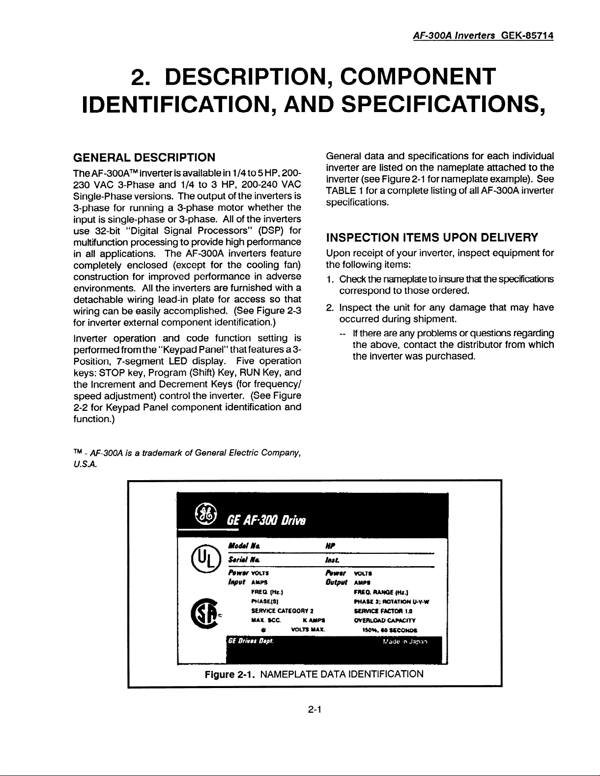
GENERAL DESCRIPTION
The AF-300ATM inverter is available in l/4 to 5 HP, 200230 VAC 3-Phase and l/4 to 3 HP, 200-240 VAC
Single-Phase versions. The output of the inverters is
3-phase for running a 3-phase motor whether the
input is single-phase or 3-phase. All of the inverters
use 32-bit “Digital Signal Processors” (DSP) for
muttifunction processing to provide high performance
in all applications.
completely enclosed (except for the cooling fan)
construction for improved performance in adverse
environments. All the inverters are furnished with
detachable wiring lead-in plate for access so that
wiring can be easily accomplished. (See Figure 2-3
for inverter external component identification.)
lnverter operation and code function setting is
performed from the “Keypad Panel” that features a 3-
Position, 7-segment LED display. Five operation
keys: STOP key, Program (Shift) Key, RUN Key, and
the Increment and Decrement Keys (for frequency/
speed adjustment) control the inverter. (See Figure
2-2 for Keypad Panel component identification and
function.)
The AF-300A inverters feature
General data and specifications for each individual
inverter are listed on the nameplate attached to the
inverter (see Figure 2-l for nameplate example). See
TABLE 1 for a complete listing of all AF-300A inverter
specifications,
INSPECTION ITEMS UPON DELIVERY
Upon receipt of your inverter, inspect equipment for
the following items:
a
1. Check the nameplate to insure that the specifications
correspond to those ordered.
2. Inspect the unit for any damage that may have
occurred during shipment.
-- If there are any problems or questions regarding
the above, contact the distributor from which
the inverter was purchased.
TM - AF-3OOA is a trademark of General Electric Company,
USA.
Figure 2-l.
NAMEPLATE DATA IDENTIFICATION
2-l
Page 14
AF300A /metiers
GEK-85714
Function indication
Program key (Shift
Up/Down keys
key)
Figure
1
2-2. KEYPAD PANEL
.
1 Stop key (Reset
COMPONENT IDENTIFICATION
Data indication
key)
Run key
KEY DESCRIPTIONS
PROGRAM (SHIFT) Key
selection key. Press to select Programming Mode
and first digit of Function Code will blink, Press to
advance selection to the next Function Code
the disired one is reached. Any data changes are
automatically set when key is pressed to advance
to another Function Code.
UP/DOWN Keys
- These keys increase or decrease
the frequency (or speed) of the inverter when in the
Operating Mode. When in Program Setting Mode,
they change the Function Code or Data Code
values.
RUN Key
- Key is used for starting operation. This
key does not function when Data Code is set for
external (control terminal) operation (Function Code
012 and 013).
STOP (RESET) Key
operating normally and Resets any Fault Trips
when inverter has stopped abnormally. The STOP
function of this key causes the inverter to trip on
OH2 when Function Code 01 is set to REMOTE
(012 or
013).
When the inverter trips, the motor will
coast to stop.
- Programming Mode
until
- Stops inverter when it is
INDICATOR DESCRIPTIONS
FUNCTION INDICATOR
indicated by the second
the
Programming
Mode*. When in the Operating
Mode, setting frequency, output frequency , and
alarm messages are indicated.
DATA INDICATOR
- Data Code is indicated by the
first and second digits when in the Programming
Mode*. When in the Operating Mode, setting
frequency, output frequency, and alarm messages
are indicated.
*When looking at Function Codes 00 through 04,
the data is in the first digit and the Function Code is
in the second and third digits.
Function Codes 7 through f, the data is in the first
and second digits and the Function Code is in the
third digit.
- Function Code is
and third digits when in
When looking at
2-2
Page 15
l/4 to 1.0 HP Units
AF300A /metiers GEK-85714
VENTILATION HOLE
BLIND PLA’TE
VENTILATION HOLE
BLIND PLATE
MOUNTING HOLE
VENTILATION HOLE
BLIND PLATE
CABLE INLET
PLATE
RUBBER BUSHING
(PROVIDED LOOSE)
NAME PLATE
7
pCABLE INLET
PLATE
SCREW
TERMINAL COVER
FOR&
Figure 2-3.
L-
NAM
: PLATE
LCOOLING
FAN
2 to 5 HP Units
TYPICAL INVERTER COMPONENTS
2-3
RUBBER BUSHING
(PROWED LOOSE)
Page 16
AF300A
/metiers GEK-85714
TABLE 1: AF-300A INVERTER STANDARD SPECIFICATIONS
ITEM
3=Phase, 200-230V lnverter HP
Standard Applicable
Motors - 230V (KVV)
OUTPUT:
Rated Capacity-230V (KVA)
Rated Output Current-230V (Amps)
Rated Output Voltage (*I)
Rated Output Frequency
Overload Current Rating
POWER SUPPLY:
Rated input AC Voltage
Allowable
Control System
Output Frequency Range
Fluctuations
I
l/4 l/2 1.0
0.2 0.4 0.8
0.57
1.10 1.90 3.00 4.20
1.5 3.0 5.0
3-Phase, 3-Wire Type, 200-230 VAC
50 Hertz, 60 Hertz, 100 Hertz, 120 Hertz
150% for 1 minute duration (inverse time characteristic)
3-Phase, 3-Wire Type, 200-230 VAC, 50/60 Hertz
170 - 253 VAC; Voltage Unbalance - +/-3%; Frequency - +/-50/o
Sinusoidal PWM Control
I
0.5 - 120 Hertz
I
SPECIFICATION
2.0 3.0 5.0
1.5 2.2 3.7
6.50
8.0 11 17
I
f
I
I
1
1
1
1 -Phase, 200-240V lnverter HP
Standard Applicable
Motors - 230V (KW)
OUTPUT:
Rated Capacity-230V (KVA)
Rated Output Current-230V (Amps)
Rated Output Voltage (*I)
Rated Output Frequency
Overload Current Rating
POWER SUPPLY:
Rated input AC Voltage
Allowable Fluctuations
Control System
Output Frequency Range
l/4
l/2 1.0 2.0 3.0
0.2
0.4 0.8 1.5 2.2
0.57
1.10 1.90 3.00 4.20
1.5
3.0 5.0 8.0 11
3-Phase, 3-Wire Type, 200-240 VAC
I
50 Hertz, 60 Hertz,
150% for 1 minute duration (inverse time characteristic)
1 -Phase, 2-Wire Type, 200-240 VAC, So/60 Hertz
170 - 257 VAC; Frequency - +/-5%
I
Sinusoidal PWM Control
I
0.5 - 120 Hertz
I
100 Hertz, 120 Hertz
1
1
1
1
1
(*l)
It is not possible for output voltage to exceed power supply voltage.
2-4
Page 17
AF-300A lnverters GEK-85714
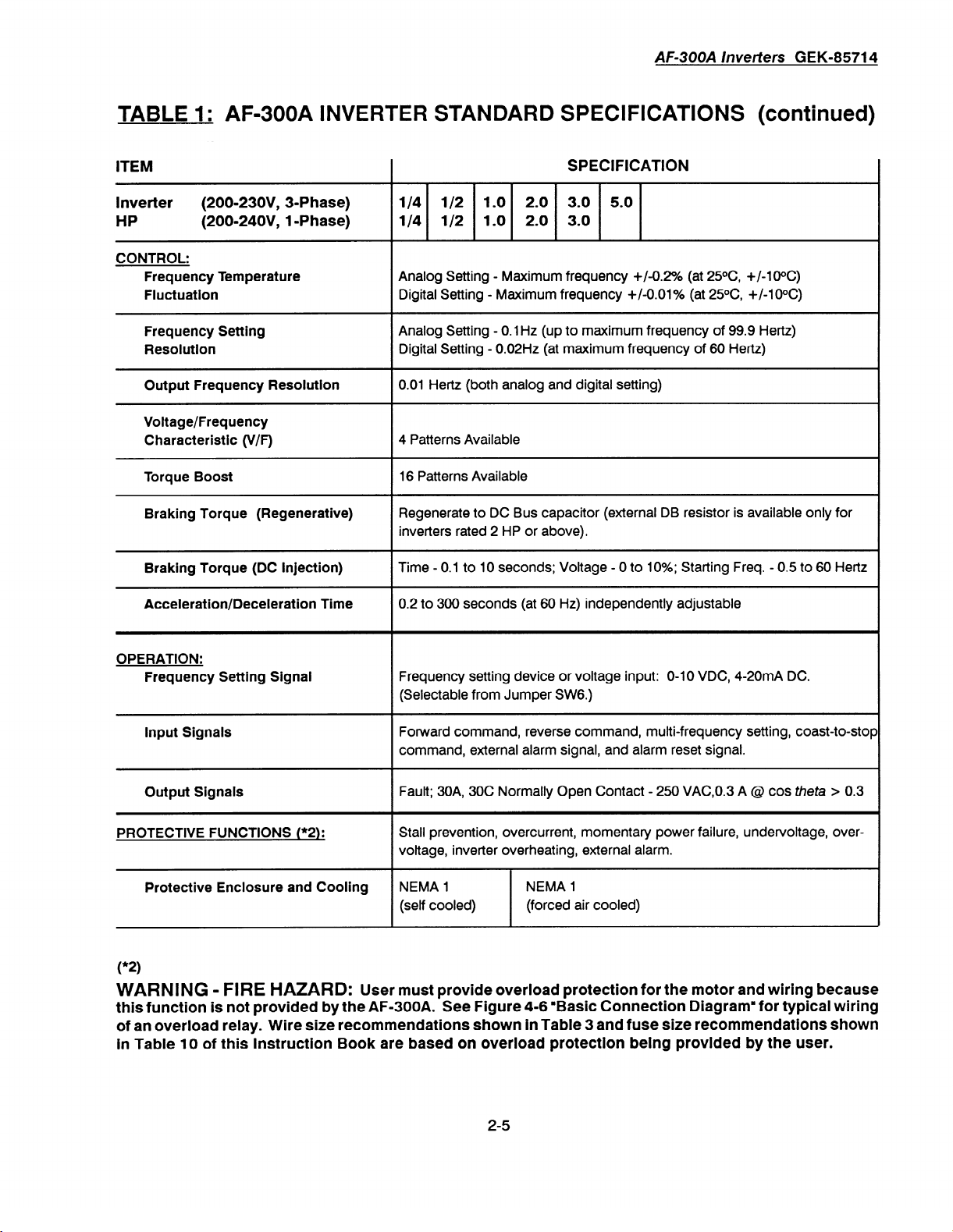
TABLE 1: AF-300A INVERTER STANDARD SPECIFICATIONS (continued)
ITEM
lnverter
HP
CONTROL:
Frequency Temperature
Fluctuation
Frequency Setting
Resolution
Output Frequency Resolution
Voltage/Frequency
Characteristic (V/F)
Torque Boost
Braking Torque (Regenerative)
Braking Torque (DC injection)
Acceleration/Deceleration Time
(200=23OV, 3-Phase)
(200=24OV, 1 -Phase)
SPECIFICATION
l/4 l/2 1 .o 2.0 3.0 5.0
l/4 l/2 1.0 2.0 3.0
Analog Setting - Maximum frequency +/-0.2% (at 25OC, +/-1gOC)
Digital Setting - Maximum frequency +/-0.01% (at 25OC, +/-1oOC)
Analog Setting - 0.1 Hz (up to maximum frequency of 99.9 Hertz)
Digital Setting - 0.02Hz (at maximum frequency of 60 Hertz)
0.01 Hertz (both analog and digital setting)
4 Patterns Available
16 Patterns Available
Regenerate to DC Bus capacitor (external DB resistor is available only for
inverters rated 2 HP or above).
Time - 0.1 to 10 seconds; Voltage - 0 to 10%; Starting Freq. - 0.5 to 60 Hertz
0.2 to 300 seconds (at 60 Hz) independently adjustable
OPERATION:
Frequency Setting Signal
Frequency setting device or voltage input: O-10 VDC, 4-20mA DC.
(Selectable from Jumper SW6.)
input Signals
Fonnrard command, reverse command, multi-frequency setting, coast-to-stop
command, external alarm signal, and alarm reset signal.
Output Signals
PROTECTIVE FUNCTIONS (“2):
Fault; 30A, 30C Normally Open Contact - 250 VACO.3 A @ cos theta > 0.3
Stall prevention, overcurrent, momentary power failure, undervoltage, overvoltage, inverter overheating, external alarm.
Protective Enclosure and Cooling
*
( 2)
WARNING - FIRE HAZARD:
NEMA 1
(self cooled)
User must provide overload protection for the motor and wiring because
NEMA 1
(forced air cooled)
this function is not provided by the AF-300A. See Figure 4-6 “Basic Connection Diagram” for typical wiring
of an overload relay. Wire size recommendations shown In Table 3 and fuse size recommendations shown
in Table 10 of this Instruction Book are based on overload protection being provided by the user.
2-5
Page 18
AF-300A
ltwerters GEK-85714
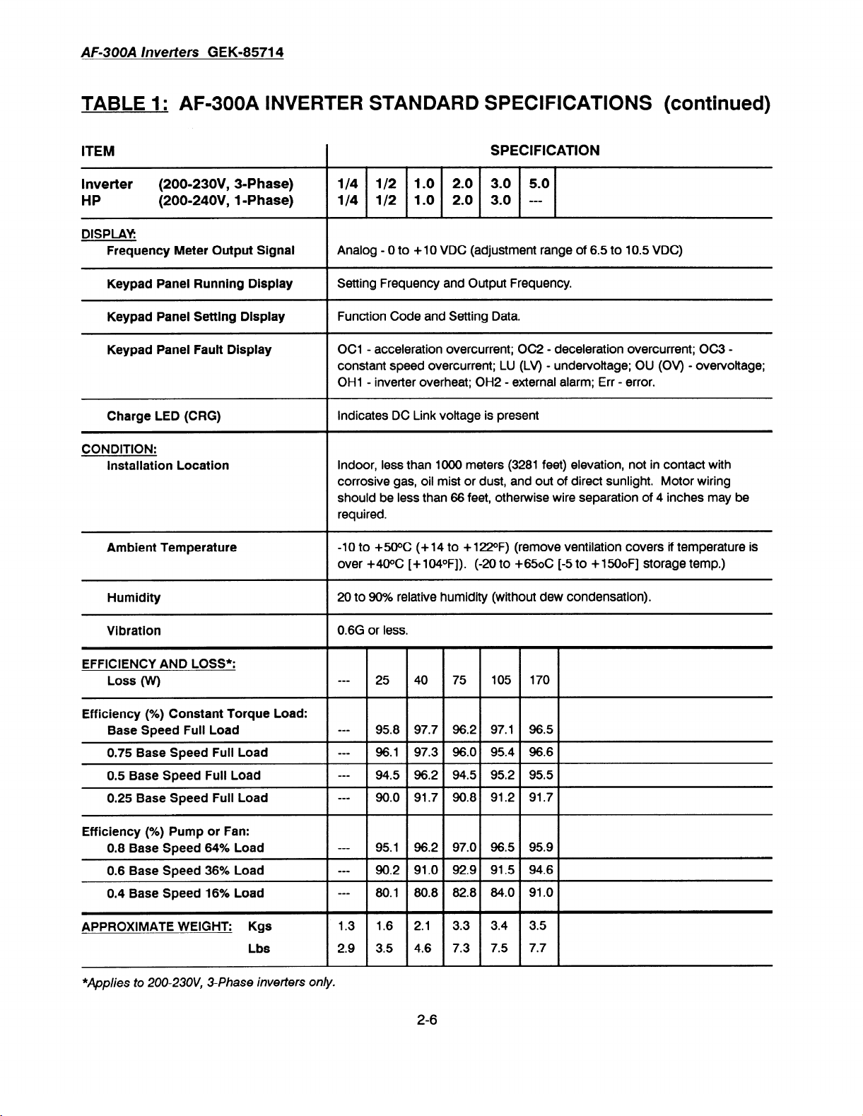
TABLE 1: AF-300A INVERTER STANDARD SPECIFICATIONS (continued)
ITEM
lnverter
HP
(200=23OV, 3-Phase)
(200=24OV, 1 -Phase)
Frequency Meter Output Signal
Keypad Panel Running Display
Keypad
Panel Setting Display
Keypad Panel Fauit Display
Charge LED (CRG)
CONDITION:
installation
Ambient Temperature
Location
SPECIFICATION
l/4 l/2 1.0 2.0 3.0 5.0
l/4 l/2 1 .o 2.0 3.0 ---
Analog - 0 to + 10 VDC (adjustment range of 6.5 to 10.5 VDC)
Setting Frequency and Output Frequency.
Function Code and Setting Data.
OCl - acceleration overcurrent; OC2 - deceleration overcurrent; OC3 constant speed overcurrent; LU (LV) - undervoltage; OU (OV) - overvottage;
OH1 - inverter overheat; OH2 - external alarm; Err - error.
Indicates DC Link voltage is present
Indoor, less than 1000 meters (3281 feet) elevation, not in contact with
corrosive gas, oil mist or dust, and out of direct sunlight. Motor wiring
should be less than 66 feet, otherwise wire separation of 4 inches may be
required.
-10 to +WC (+ 14 to + 122oF) (remove ventilation covers if temperature is
over +40% [ + 1040F]). (-20 to
+650C (-5
to +
1500F]
storage temp.)
Humidity
Vibration
EFFICIENCY AND LOSS*:
Loss (W)
Efficiency (%) Constant Torque Load:
Base Speed Full
0.75 Base Speed Full
0.5 Base Speed Full Load
0.25 Base Speed Full Load
Efficiency (%) Pump or Fan:
0.8
Base Speed 64%
Load
Load
Load
0.6 Base Speed 36% Load
0.4 Base Speed 16% Load
APPROXIMATE WEIGHT: Kgs
Lbs
*Applies to 200-23OV, 3-Phase inverters only.
20 to 90% relative humidity (without dew condensation).
0.6G
or less.
o-0
25 40 75
w-0
95.8 97.7
-00
96.1 97.3 96.0 95.4 96.6
o-0
94.5 96.2 94.5 95.2 95.5
0-a
90.0
91.7 90.8 91.2 91.7
-00
95.1 96.2 97.0 96.5 95.9
m-0
90.2
91.0 92.9 91.5 94.6
o-0
80.1 80.8 82.8 84.0 91 .O
1.3 1.6 2.1
2.9 3.5 4.6 7.3 7.5 7.7
105 170
96.2
97.1 96.5
3.3 3.4 3.5
2-6
Page 19
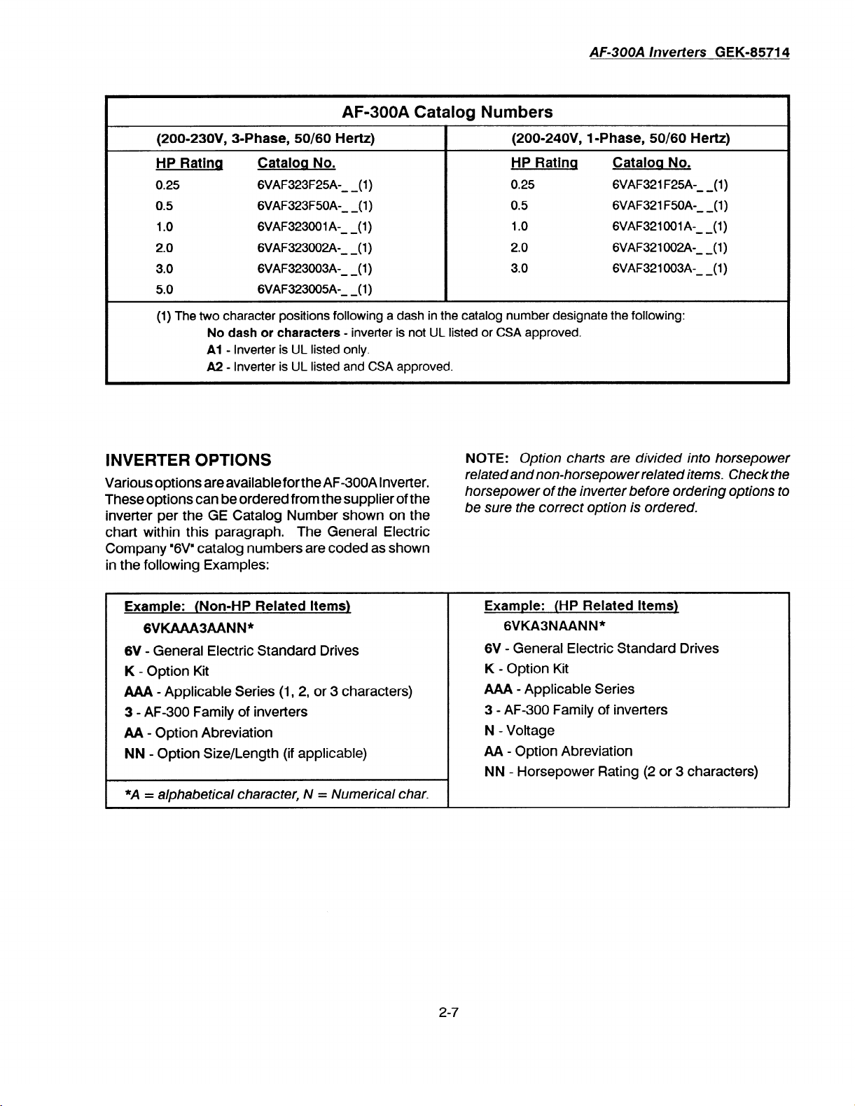
AF-300A Catalog Numbers
AF-300A lnveflers
GEK-85714
(200=23OV, 3=Phase, SO/SO Hertz)
HP Rating
0.25 6VAF323F25A- (1) 0.25
0.5 6VAF323F50A- (1) 0.5
1.0 6VAF323OOlA- (1) 1.0
2.0 6VAF323002A- (1) 2.0
3.0 6VAF323003A- (1) 3.0
5.0 6VAF323005A- (1)
(1) The two character positions following a dash in the catalog number designate the following:
No dash or characters
Al
A2 - lnverter is UL listed and CSA approved.
Catalog No.
--
--
--
--
--
--
- inverter is not UL listed or CSA approved.
- lnverter is UL listed only.
INVERTER OPTIONS
Various options are availableforthe AF-300A Inverter.
These options can be ordered from the supplier of the
inverter per the GE Catalog Number shown on the
chart within this paragraph. The General Electric
Company “6Vn catalog numbers are coded as shown
in the following Examples:
NOTE:
(200.24OV, 1 -Phase,
HP Rating Cataloq No.
Option charts are divided into horsepower
50/60
Hertz)
6VAF321 F25A- (1)
6VAF321 F50A- (1)
6VAF321OOlA- (1)
6VAF321002A- (1)
6VAF321003A- (1)
--
--
--
--
--
related and non-horsepower related items. Check the
horsepower of the inverter before ordering options to
be sure the correct option is ordered.
Example: (Non-HP Related Items)
GVKAAA3AANN*
6V
- General Electric Standard Drives
K
- Option Kit
AAA - Applicable Series (1, 2, or 3 characters)
3 - AF-300 Family of inverters
AA - Option Abreviation
NN - Option Size/Length (if applicable)
*A = alphabetical character, N = Numerical char.
Example: (HP Related Items)
6VKA3NAANN*
6V - General Electric Standard Drives
K
- Option Kit
AAA - Applicable Series
3 - AF-300 Family of inverters
N - Voltage
AA - Option Abreviation
NN - Horsepower Rating (2 or 3 characters)
I
2-7
Page 20
AF-300A
lnverters GEK-85714
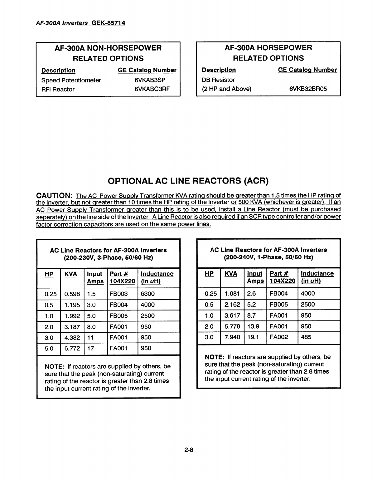
AF-300A NON-HORSEPOWER
RELATED OPTIONS
Description
Speed Potentiometer 6VKAB3SP
RFI Reactor 6VKABC3RF
GE Catalog Number
Description
DB Resistor
(2 HP and Above)
AF=300A HORSEPOWER
RELATED OPTIONS
GE Cataloq Number
6VKB32BR05
OPTIONAL AC LINE REACTORS (ACR)
CAUTION:
the Inverter,
AC Power Supply Transformer qreater than this is to be used, install a Line Reactor (must be purchased
seperately) on the line side of the Inverter. A Line Reactor is also required if an SCR type controller and/or power
factor correction
The AC Power Supply Transformer KVA ratinq should be qreater than 1.5 times the HP ratinq of
but
not qreater than IO times the HP ratinq of the lnverter or 500 KVA (whichever is qreater).
capacitors
are used on the same power lines.
If an
AC Line Reactors for AF-300A lnverters
(200=23OV,
HP WA Input Part #
0.25 0.598
05 . 1.195
10 . 1.992
2.0 3.187
3.0 4.382
5.0 6.772
NOTE:
sure that the peak (non-saturating) current
rating of the reactor is greater than 2.8 times
the input current rating of the inverter.
If reactors are supplied by others, be
3=Phase, SO/SO Hz)
Inductance
Amps lin uH)
1.5 FB003
3.0 FB004
5.0
8.0
11 FAOOI
17 FAOOI
104X220
FBOO5
FAOOI
6300
4000
2500
950
950
950
AC Line Reactors for AF-300A lnverters
(200-24OV,
HP WA Input Part #
0.25
1 1.081 1 2.6
0.5
1 2.162 1 5.2 1 FBO05 1 2500
1 .O 1 3.617 1 8.7
2.0 1 5.778 1 13.9 1 FAOOI
3.0 7.940
NOTE:
sure that the peak (non-saturating) current
rating of the reactor is greater than 2.8 times
the input current rating of the inverter.
If reactors are supplied by others, be
1 -Phase, SO/SO Hz)
104X220
1 FBO04 1 4000
1 FAOOI
19.1 FA002
Inductance
(in uH) Amps
1 950
1 950
485
2-8
Page 21

AF-300A
/metiers GEK-85714
3. INSTALLATION GUIDELINES
INSTALLATION ENVIRONMENT
Install the inverter in a location that meets the following requirements:
-0
The ambient temperature is between -1oOC
and +5OC* (+14oF to +122oF).
-- The relative humidity is between 20% and 90%.
Avoid any location subject to dew condensation, freezing, or where the inverter would come
in contact with water.
-- Do not install in any location subject to direct
sunlight, dust, corrosive gas, inflammable gas,
water vapor, or oil mist.
-0
The inverter should be installed at an elevation
below 1000 meters (3281 feet) and vibration
should be less than 0.6G.
-- Wiring from lnverter to motor should be less
than 66 feet, otherwise a separation of 4 inches
may be required.
INSTALLATION MOUNTING
CLEARANCE
NOTE:
When installing two or more inverters
in close proximity, allow sufficient space as
shown in Figure 3-1 and install them in a horizontal row.
-0
See the appropriate view in Figure 3-2 for the
location and size of mounting holes.
-0
Install the rubber bushings supplied with the
inverter into the cable openings in the wiring
lead-in plate to prevent cable damage and to
minimize dust entry.
*+5(X is the maximum allowable ambient temperature with the ventilation cover removed. When ventilation cover is kept in p/ace, maximum ambient tem-
perature is 40°C (105°F).
CAUTION:
affects inverter life and reliabilitv, do not install the
inverter in anv location that exceeds the allowable
temperatures.
-- Install the inverter perpendicular to the ground
and with the lettering right side up. (If the
inverter is installed up-side-down or horizontally, heat build-up will occur.)
-- Install at a sufficient distance from other equipment, walls, or wiring ducts as shown in Figure
3-l (these clearances are required to allow for
proper cooling air circulation).
CAUTION:
ture of the cooling fins of the inverter rise to
proximatelv 90 degrees C (194 degrees F). For
this reason, the mounting wall must be of heat
resistant material.
Because the ambient temperature greatly
During operation, the tempera-
ap-
Figure 3-l.
Ovw
5’hhe*
(12 cm)
I
INVERTER MOUNTING CLEARANCE
(Open Installation)
3-l
Page 22

AF300A lnverters
GEK-85714
j-244,
(62)
370
'-66.5i-
,1.06
(271
-’ b.25 (61
l/2 HP UNITS*
Cable irdel
mlrl rubber
bus'ling
-6.69 (170 1-q
4
&25(6)
c&Ilk iiu
willl rubber
bushing .
-- .
1
1.32
w S!
l/4
HP UNITS
4 "
Caue nlet
tithrubber
bushirq
-- .
-I
2.70
(se 3
-i
m Rubber
1 .O HP UNITS *
bushing dimensions
Figure
2
to
5 HP UNITS
*For
1 -Phase versions
inverters, the 6.69 inch (170 mm) and 6.10 inch
(155 mm) dimensions are 8.7 inches (221 mm)
and 8.1 inches (206 mm) respectively. All other
dimensions remain as shown.
3-2. INVERTER EXTERNAL DIMENSIONS
3-2
of the l/2 and
1 .O
HP
Page 23

AF300A /metiers
GEK-85714
4.
WIRING PROCEDURES
REMOVE TERMINAL BLOCK COVER
Remove the terminal block cover as follows (see
Figure 4-l):
1. Remove the screw located at the bottom of the
cover (l/4 to 1.0 HP inverters do not have this
screw).
2. Press upward on bottom of cover and lift off.
3. See the appropriate view of Figure 4-1 for the
location of the
the
Control Circuit Terminal Block.
Main Circuit Terminal Block
and
MAIN CIRCUIT WIRING
CAUTION:
connected to the U, V, W terminals or the N, P, P, DB
terminals.
1. Connect the incoming AC power supply wires to
the terminals of the Main Circuit Terminal Block as
shown in the appropriate view of Figure 4-2.
TABLE 2 for description of all terminals and TABLE
3 for application wiring list.)
Be sure that the power supply is never
(See
NOTE:
Motor will rotate counterclockwise when
viewed from the load side when connected normaly.
If the motor rotates in reverse direction, interchange
any two of the U, V, or W terminal connections.
3. Connect the ground terminal as shown in the
appropriate view of Figure 4-2. (Do not operate
without the unit being grounded.)
-- The ground wire must be as large and short as
possible (see TABLE 3 for application wiring
.
.
list)
CONTROL CIRCUIT WIRING
lnverter is wired at shipment for operation and frequency setting through the
is set at 60 Hertz).
-- See Figure 4-3 for wiring connections.
-- See TABLE 2 for description of all terminals.
Make wire connections as shown in Figure 4-4 for
external operation
-- See TABLE 2 for description of all terminals.
through control circuit terminals.
keypad panel
(frequency
2. Connect the 3-phase motor wires to the U, V, and
W terminals of the Main Circuit Terminal Block as
shown in the appropriate view of Figure 4-2.
TABLE 2 for description of all terminals and TABLE
3 for application wiring list.)
Loo*en
SU8W
Figure 4-1.
(See
TERMINAL BLOCK COVER
Push up W@
and the cow
will be refnoved
88SllY
I
Control &cut
A
Main &cut tefmlnal
terminal
4-l
Page 24

AF300A
lnverters GEK-85714
l/4 to 1 .O HP lnverters
I I -
Ll L3
50/60
Hz, l-Phase AC
200-240
f
u v bJ
INDUCTION MOTOR
Volts
2 and 3 HP lnverters
3-Pt-msE
-
- 1
Figure 4-2 (Part 1 of 2).
2
CR
?
W/60
)
200-240 Volts
)
?
Hz, l-Phase AC
Tt-ERMfX
3-WRSE
INDUCTION MOTOR
+
RELAY
POWER CIRCUIT WIRING CONNECTIONS FOR I-PHASE INVERTERS
4-2
Page 25

AF-300A hverters
GEK-85714
l/4 TO 1.0 HP
50/60 HZ, 3-PHRSE AC
288 to 230 VOLTS
2
TO 5 HP
UNITS
3-FvwSE
INDUCTION MOTOR
UNITS
Figure
4-2
(Part 2 of 2).
Ll
L2 L3 N P P DB U V W
1
-
'r'4y?
2
-
- 1
’ ’ ’ - ACR
CB
Y- Y’ Y’
50/60 HZ, 3-PHfSE RC
200 to 230 VCXTS
\
6 \ \
5
\
3-PI-WE
INDUCTION MOTW
THERMFtL
+
RELRY
POWER CIRCUIT WIRING CONNECTIONS FOR 3-PHASE INVERTERS
4-3
Page 26

AF300A /metiers
v t
30C 30A THR RST/BX FWD REV FM Xl X2 1 1 12
I
-
GEK-85714
l/4
TO 1.0 HP UNITS
L
13 CM
2
TO 5 HP UNITS
AF-388FI
CM 11 12 13 FM THR RST/BX FWD REV Xl
c
TOR
FP
T RMAL
RELfW SWITCH
IA/
EXTERNFIL
THERMAL
I
I
X2 30C 30Fl
-
F-
Xl CAUTION:
REMOVE JUMPER FROM BETWEEN
TERMINfXS THR AND CM NHEN
THERMAL INTERLOCKS WE USED.
XZ CWTION:
REMOVE 3UMfER FROM BETWEEN
TERMINALS FWD f3ND CM.
NOTE: SET FUNCTION CODE 01= 0.
Figure 4-3
Operation From Keypad
(Part 1 of 2). CONNECTIONS FOR OPERATION THROUGH KEYPAD PANEL
4-4
Page 27

RF-388A
30C
l
I
-
AF-3OOA Invertem
l/4
TO 1.0 HP UNITS
~.
30A
THR RST/BX FWD REV FM Xl X2 1 1 12 13 CM
*2
FWD
MOTOR
TmF7-
A’
kr
*1
GEK-85714
.
>
HF-388A
CM 11 12
2
TO 5 HP UNITS
13 FM THf? RST/BX FWII REV Xl
1
X2 30C 30R
Xl
CRUTION:
REMOVE JJUMPER FROM BETWEEN
TERPlINflLS THR AND CM WHEN
THERMFtL INTERLOCKS FRE USED.
X2 CFlUTION:
REMOVE JUMPER FROM BETWEEN
TEf?MINALS
NOTE: SET FUNCTION CODE 01s 0.
FWD f'3ND
CM.
Operation From Keypad With Reversing Capability
Figure 4-3
(Part 2 of 2). CONNECTIONS FOR OPERATION THROUGH KEYPAD PANEL
4-5
Page 28

AF-300A
/metiers GEK-85714
l/4
TO
1.0
HP UNITS
r
30C 30FI THR RST/BX FWD REV FM Xl X2 1 1 12
I
I
MOTOR
THERMFIL
RELfIY
XTERNFIL
F
l-l RMRL
SW TCH 5
I
*1
2
TO 5 HP UNITS
RF-38WI
1
CM
1 I
11 12
1 I I
13 FM THR RST/BX FWD REV Xl
I
I
13 CM
I I
SPEED
lKR, 1/2W
1
POT
X2 30C 30A
*
+
.
t
i
w
FLED1 /p2owT
9
MOTOR EXTERML
THERMAL
RELFIY
THERMRL
SWITCH
Xl
CAUTION:
REMOVE JUMPER FROM BETWEEN
TERMINRLS THR AND CM WHEN
THERMAL
X2
CFKJTION:
REMOVE JUMPER
TERMINFILS FWD
NOTE: SET FUNCTION CODE 81= 3.
INTERLOCKS
r
ARE
USED.
FROM BETWEEN
F)ND
CM.
Operation From Remote
Figure
4-d (Part 1 of 2). CONNECTIONS FOR CONTROL CIRCUIT TERMINAL OPERATION
4-6
Page 29

l/4
TO 1.0 HP UNITS
.
30C 30A THR RST/BX FWD REV FM
1
I
*2
AF-300A
Xl X2 11 12
SPEED POT
lKn,
/metiers GEK-85714
13
.
143
CM
RF-388A
CM I1 12
(XX9
I
2
TO 5 HP UNITS
.
13 FM THR RST/BX FWD REV Xl
*2
1
x2 30c 3OA
I
-
#l
CRUTION:
REMOVE JUMPER FROM BETEEN
TERMINF)LS THR
THERMHm INTEf?LOCKS f+?E USED.
#2
CHJTION:
REMOVE JUMPER FROM BETEEN
TERMINFILS FWD fbdl CM.
NOTE: SET FUNCTION CODE 81~ 3.
AND
CM I44EN
Figure
Operation From Remote With Reversing Capability
4-4 (Part 2 of 2). CONNECTIONS FOR CONTROL CIRCUIT TERMINAL OPERATION
4-7
Page 30

AF-300A lnverters GEK-85714
CAUTION:
The contrd circuit terminal wiring should
be kept as far awav as possible from the main power
wirino to prevent operational error due to noise interference. Never install both tvpes of wiring in the same
duct or conduit. (A separation distance of 10 centimeters [4 inches] or more is recommended.) If the
control circuit wiring must cross the main power wiring, it should cross at a right angle.
CAUTION:
Use shielded or twisted wire for the
control circuit wiring (wiring should be as short as
possible, i.e. 20 meters 165 feet] or less). (Connect
outer covering of the shielded wires to the inverter
ground terminal and leave the other end open, but
taped.)
CAUTION:
Install a suppressor in parallel with any
relays or solenoid type coils, etc. that may be close to
the inverter.
OPTIONAL EXTERNAL DYNAMIC
BRAKING RESISTOR UNIT WIRING
NOTE:
CM - THR terminals. If the jumper is not removed, the
OH2 alarm will not function during operation.
When frequent braking or high torque braking is
required, connect the optional braking resistor as
shown in Figure
OWL
CAUTION:
nals are inadvertently short-circuited, damage to the
inverter will result.
CAUTION:
used except for inverters above 1.5 KW (2 HP).
WARNING - FIRE HAZARD: Use
namic braking resistors that are provided by GE
Drive Systems. These are special resistors that
have a thermal fuse built in that opens if the
resistor gets too hot. This fuse should only open
if the DB transistor in the inverter or DB unit fails
short circuited. The resistor will need to be replaced if this happens.
Remove the factory installed jumper from the
4-5
(available for
If the P-DB terminals or the P-N termi-
The external braking resistor cannot be
2-5
HP inverters
only dy-
Figure
\
2 TO 5 HP UNITS ONLY
CM [
Ll L2 L3 N P P DE U V W
THERMAL
FUSE
1 THR 1
I
P DB 1 2
.
I
BRAKING
RESISTOR
I I
L
L
THERMAL
SWITCH
1
/
4-5. OPTIONAL EXTERNAL DYNAMIC BRAKING RESISTOR UNIT WIRING CONNECTIONS
4-8
Page 31

AF300A lnverters GEK-85714
* THERWiL RELAY
Ll
I
*-OPTION
RF-300fl
3
n
13
12
11
E(G)
E(G)
DB
N
SISTOR UNIT
P
P
Q
AND
,-----e---w-,
-
GROUND
FIBOVE 1
ANY F)DDITICMK
NOfWRLY CLOSED
INTERLOCKS
BE ADCUI
8
I
:
I
f
I
SHOULD ’
IN
SERIES
I 3:
Figure 4-6.
BASIC CONNECTION DIAGRAM
4-9
Page 32

AF-300A hverters GEK-85714
TABLE 2: TERMINAL IDENTIFlCATION/FUNCTlON
Terminal Terminal
Label
MAIN
CIRCUIT:
L1 J-a
L3
Name
AC Supply Line
Input Terminals
Function
Connection for commercial power (ZOO-230 VAC).
ww
P,DB
W
E (G)
CONTROL
INPUT:
11
12
13
lnvefter
Terminals
External Braking
Resistor Terminals
External DC Bus
Terminals
Ground Terminal
Frequency Setting
Common Terminal
Frequency Setting
Signal Input
Frequency Setting
Power Supply Term.
Control Circuit
Common Terminal
Output
Connection for 3-phase induction motor.
Connection for external braking resistor (1.5 KW (2 HP] or more).
May be used to check DC bus voltage. Not present on
on l/4 to 1 .O HP inverters.
Connection for ground.
Voltage setting and current setting common terminal. (Do not
connect to CM terminal as they are not isolated.)
0 to + IO VDC input when SW6 is in the 2-3 position.
4 to 20 milliamp input when SW6 is in the 1-2 position.
Regulated + 10 VDC power supply for speed pot only, 1 OmA
maximum output current (with respect to terminal 11).
Common terminal for control input/output commands. (Do not
connect to terminal 11 as they are not isolated.)
FWD
REV
RST/BX
THR
Forward Command
Input Terminal
Reverse Command
Input Terminal
~-
External RESET and/
or Coast-To-Stop
External thermal relay,
external braking resis-
tor thermostat terminal
Forward command via FWD-CM (closed). Reverse command via
REV-CM (closed). When FWD-CM is closed and REV-CM is closed
at the same time, the inverter will decelerate to stop.
Signal during STOP due to fault - Alarm RESET
Signal during Act. and steady state running to STOP - Inactive
Signal during Dec.
With THR-CM (open), motor will coast-to-stop.
NOTE:
thermostat, the THR-CM terminals must be closed or the inverter will
not operate.
With no external thermal relay or external braking resistor
4-l 0
- Motor will coast-to-stop
Page 33

AF300A /metiers GEK-85714
TABLE 2: TERMINAL lDENTIFICATION/FUNCTlON
Terminal
Label
CONTROL
INPUT:
(cont.)
Xl, x2
Terminal
Name
Multi-step Frequency
Operation Command
Input Terminals
Number 2 Acc./Dec.
Selection (when set as
poq, [900])
Function
Xl -CM
X2-CM
Selected
Freq.
Xl -CM
X2-CM
Selected
Freq.
Acc./Dec.
OFF
OFF
Touch Panel/
Terminal 12
OFF
OFF
Touch Panel/
Terminal 12
Act. (F.C. 4)
Dec. (F.C. 5)
ON
OFF
Multi-Freq.
Setting 1
(F.C. 7)
ON
OFF
Multi-Freq.
Setting 1
(F.C. 7)
Act. (F.C. 4)
Dec. (F.C. 5)
(continued)
OFF
ON
Multi-Freq.
Setting 2
(F.C. 8)
OFF
ON
Touch Panel/
Terminal 12
Number 2
AccJDec.
(F.C. 6)
ON
ON
Multi-Freq.
Setting 3
(F.C. 9)
ON
ON
Multi-Freq.
Setting 1
(F.C. 7)
Number 2
Acc./Dec.
(F.C. 6)
CONTROL
OUTPUT:
30A
3oc
Analog Frequency
Meter Terminal
Fault Relay Output
Terminals
Outputs + 10 VDC at maximum frequency and is proportional to
output frequency down to 0 VDC. Adjustable maximum voltage of
+6.5 to + 10.5 VDC.
DC Volt Meter internal impedance over 1 OK ohm can be connect-ted
to this terminal (maximum two).
During normal operation, the relay is not energized. When a fault
is detected, the relay is energized and contact is made between 30A
and 30C. (Contact rating resistive load: 250 VAC, 0.3 Amps @ cos
theta > 0.3)
4-l 1
Page 34

AF300A
lnverters GEK-85714
WARNING - FIRE HAZARD:
User must provide overload protection for the motor and wiring because
this function is not provided by the AF-300A. See Figure 4-6 “Basic Connection Diagram” for typical wiring
of an overload relay. Wire size recommendations shown in Table 3 and fuse size recommendations shown
in Table 10 of this Instruction Book are based on overload protection being provided by the user.
TABLE 3: APPLICATION OF WIRING AND EQUIPMENT
I
ITEM
Inverter
HP
,
Standard Applicable
Motor Output-230v (KW)
Rated
Capacity-230V (KVA) (*I)
Applicable
Main Circuit Wiring (200-23OV, 3-Ph.)
Main Input Circuit Wiring
(200=24OV,
Main Output Circuit Wiring
(200,24OV, I-Phase)
Control Circuit Wiring
.
Wire Sizes (AWG) (*2)
l-Phase)
114
0.2 0.4 0.8
0.57 1.1 1.9
14 14 14
14 14 14
14 14 14
m
20 (twisted, shielded)
SPECIFICATION
1.0
2.0 3.0 5.0
1.5 2.2 3.7
3.0 4.2 6.5
14 14 12
12 10 N/A
14 14 N/A
”
I
(*I)
Indicates rated capacity when rated output voltage is 230
(*2) Standard wire is 600V vinyl wire.
VAC.
4-12
Page 35

AF-300A lnverters
5. INVERTER OPERATION
GEK-85714
PRE-OPERATION INSPECTION
After mounting and wiring has been completed, check
the
inverter for the following items before applying AC
power:
--
Check for
wiring).
-- Verify that there are no wiring chips, screws,
etc. remaining in the inverter.
-- Check that all screw and terminal connections
are
-- Verify that no exposed wire ends are touching
other terminals.
WARNING -
HAZARD:
FWD-CM or REV-CM terminals connected, the
driven motor starts automatically at Power-Up or
by pressing the RESET key to reset the inverter.
When AC
RUN
key is pressed,
according to the
(Use
the
STOP
If a test run is desired,
frequency of around
a safe manner and
-- Smooth
-- Correct direction
-- Any abnormal vibration or noise in the motor.
-- Smooth speed increase and speed reduction.
wiring errors (especially main circuit
tight.
MECHANICAL MOTION
When &wire control is used with the
power is
applied to the inverter and the
operation will be at 60 Hertz
Function Code set at the factory.
key to
halt operation.)
run the inverter at a low
5 Hertz. Conduct the test run in
check for the following:
rotation of motor.
of rotation.
CAUTION:
the inverter terminals or control circuit terminals. For
meooer testing method, refer to Section 6, Maintenance and Inspection.
Do not conduct meager tests between
SELECTION OF OPERATING METHOD
The AF-300A provides five type of operating methods. See TABLE 4
for list of operating methods and
refer to Figure 5-1 for identification of the components
of
the Keypad Panel.
FUNCTION CODE AND DATA
SETTING PROCEDURES
In order that the inverter (including the motor) may
operate under optimum conditions, Function Code
data setting changes may be required. This
graph is a general explanation of the Function Code
data setting methods.
NOTE: Complete details
are shown in TABLE
10:
Function Code Descriptions. Be sure to fully
for Function Code settings
9:
Function Codes, and TABLE
understand all Function Codes.
para-
TABLE
Method # RUN & STOP
RUN Key
,
STOP/RESET Key
External Signal
FWD and REV Term.
Multi-Frequency Setting (maximum of 4 steps)
-- #I Frequency is set by Function Code
-- #2, #3, and #4 Frequencies are set by Function Codes [7 - -1, [8 - -1,
and [9 - -1 and selected by external signal combinations of Xl and X2.
I
4:
OPERATING METHODS
Frequency Setting
Increment and Decrement Keys
Potentiometer or Analog Signal
Increment and Decrement Keys
Potentiometer or Analog Signal
[Ol -1
5-1
Function Code
[Ol 0] (Factory Set)
Wll
P121
co1 31
Page 36

AF-300A lnverters
GEK-85714
Function indication
Up/Down keys
Figure
$ Program key (Shift key)
’
5-1. KEYPAD PANEL COMPONENT IDENTIFICATION
Data indication
KEY DESCRIPTIONS
PROGRAM (SHIFT) Key
selection key. Press to select Programming Mode
and first digit of Function Code will blink. Press to
advance selection to the next Function Code until
the disired one is reached. Any data changes are
automatically set when key is pressed to advance
to another Function Code.
UP/DOWN Keys
- These keys increase or decrease
the frequency (or speed) of the inverter when in the
Operating Mode. When in Program Setting Mode,
they change the Function Code or Data Code
values.
RUN Key
- Key is used for starting operation. This
key does not function when Data Code is set for
external (control terminal) operation (Function Code
012 and 013).
STOP (RESET) Key
operating normally and Resets any Fault Trips
when invetter has stopped abnormally. The STOP
function of this key does not function when Data
Code is set for external (control terminal) operation
(Function Code 012 and 013). (Pressing may
cause OH2 trip.)
- Programming Mode
- Stops inverter when it is
INDICATOR DESCRIPTIONS
FUNCTION INDICATOR
indicated by the first and second digits when in the
Programming Mode. When in the Operating Mode,
setting frequency, output frequency , and alarm
messages are indicated.
DATA INDICATOR - Data Code is indicated by the
second and third digits when in the Programming
Mode*. When in the Operating Mode, setting
frequency, output frequency, and alarm messages
are indicated.
*When looking at Function Codes
the data is in the first digit and the Function Code is
in the second and third digits. When looking at
Function Codes I through F, the data is in the first
and second digits and the Function code is in the
third digit.
- Function Code is
00
through 04,
5-2
Page 37

AF3OOA lnverters
GEK-85714
Chanqinq Function Code
Mode:
NOTE: Function
Code setting will be disp/ayed in the
Settinqs In STOP
following order when inverter is stopped:
76.
7. [00 -1
2. [Ol -1
3. [02 -1 8. [3 - -1 73. [8 - -1
4. [03-l
5. [04 -1
6. [l - -1 77. [6 - -1
7. [2 - -1 72. [7 - -1
9. [4 - -1 74. [9 - -1
70. [5 - -1 75.
[A - -1
[b - -1
77. [C - -1
78.
[d--l
79.
[E - -1
20.
[F - -1
See TABLE 5 forwfiich Function Codes can be changed
while inverter is operating.
1.
Verify operation signal
terminal signals) is completely in
(RUN
key, FWD and REV
OFF
mode.
-- The frequency that has been set will blink on
the display.
-- If display shows Function Code [030], press
STOP
key, then press and hold
PRG/SHIFT
key until the set frequency is shown (blinking).
2.
Press
PRG/SHIFT
key to change to Function Code
Setting Mode.
-- When key is pressed, Function Code will activate and display will show [000] (first digit will
be blinking).
3.
Continue to press
PRG/SHIFT
key to advance
Function Code (advances each time key is pressed)
until desired one is reached.
-- First digit of Function Code will be blinking.
4.
Press
Increment or Decrement
keys to change
data value of the selected Function Code.
-- Data will be shown in the second and third
positions of the display
Chanqinq Function Code Settinqs In RUN Mode:
NOTE:
Function Code setting will be displayed in the
following order when inverter is running:
7. [03 -1 3. [3 - -1 5. [5 - -1
2. [2 - -1 4. [4 - -1 6. [6 - -1
These are the on/y Function Codes can be changed
while inverter is operating (see TABLE
1. Press
PRG/SHIFT
key to change to Function Code
5).
Setting Mode.
-- When key is pressed, Function Code will activate and display will show [030] (first digit will
be blinking).
2.
Continue to press
PRG/SHIFT
key to advance
Function Code (advances each time key is pressed)
until desired one is reached.
-- First digit of Function Code will be blinking.
3.
Press
Increment or Decrement
keys to change
data value of the selected Function Code.
-- Data will be shown in the second and third
positions of the display
4.
Press
PRG/SHIFT
key to enter data (set in step 3)
into memory and advance to next Function Code.
-- Display will show existing data.
5. Repeat steps 2 through 4 until all desired data
changes have been completed.
-- Display will show any adjustments as they are
made.
6. Press and hold the
PRG/SHIFT
key to store the
data adjusted in step 5 and advance display to the
set frequency (not blinking).
5.
Press
PRG/SHIFT
key to enter data (set in step
into memory and advance to next Function Code.
-- Display will show existing data.
6.
Repeat steps 3 through 5 until all desired data
changes have been completed.
-0
Display will show any adjustments as they are
made.
7.
Press and hold the
PRG/SHIFT
key to store the
data adjusted in step 6 and advance display to the
set frequency (shown blinking).
lnverter is now ready for operation again.
4)
5-3
lnverter is now in Operation
Mode again.
Page 38

CONTROL CIRCUIT CONNECTION
AND OPERATION
Basic connections
Codes
[OlO]
(these connections are done at factory).
Common terminal connections
regardless of Function Code are shown in Figure
Connection description is as follows:
--
30A, 30C
circuits, etc.
--
FM
- Used for external analog meter when fre-
quency indication is needed.
- THR
- Connected to CM terminal at factory.
Connects to a normally closed contact. When
inverter STOP is desired through external alarm,
(thermal overload relay for motor, heat sensor
for DB resistor, etc.)open this contact.
RST/BX
mentary contact for resetting a fault externally
during stop.
CM
- Zero volt terminal (common).
that are required for Function
and
[Ol l]
are shown in Figure 5-2
that are required
- Fault Relay Output used for alarm
- Connects to a normally open mo-
5-3.
Keypad Panel Operation [Ol 01, [Ol l] terminal connections
that are required are shown in Figure 54.
Connection description/operation is as follows:
-- Wiring shown for this operation is FWD to CM Do Not remove this wiring.
-- Frequency Setting - If the Function Code setting is
[Oil],
the following three frequency
setting methods are available:
Connect potentiometer (1 K ohm. l/2 watt) to
terminals.1 3,
Input of 0 to +
12 (12
12,
10
is positive).
and
1 i. ’ *
VDC signal to terminals
,
11,
Connect analog current signal of 4 to 20mA
DC current signals to terminals
12, 11 (12
positive).
-- See Figure
5-5
for
RUN
Operation example.
is
l/4 to 1.0 HP Units
J--l- .
#K: 3oA THR RST!BX FWD
.
.
l/4 to 1.0 HP Units
4
? -
REV FM Xl X2 11 I2 13 CM
I I I
Figure 5-2.
i t _ A
FACTORY CONNECTIONS
CM 1 I 12 13
2 to 5 HP Units
p-7
FM THR
1
c
RST.‘BX FWD REV Xl X2 30C
I
6
3OA
4
2 to 5 HP Units
Figure 5-3.
COMMON TERMINAL CONNECTION EXAMPLE
5-4
Page 39

*
38C 38fi
CM
L
i
11
1
*
4
4
I
I
1
4
t
1
i
4
I
I
'Ax
l/4 to 1.0 HP Units
THR RST/BX FhID REV FM
A
2 to 5 HP Units
12
1
I
I
I
I
I
I
I
I
I
I
I
I
I
I
I
13
-a
b
I
4
I
I
I
t
I
I
I
#
I
I
I
I
I
FM THR
RST/BX FWD
AF-300A lnverters GEK-85714
Xl XZ 1 1 12
v
I
I
I I
I b
I I
I I
I I
I I
I
I
I b
I
I
!-xK
1
8
I
I
I
I
I
I
I
REV
A
Xl
x2 q38c 3im
13 CM
4
I
I
I
I
I
I
4
I
I
I
I
I
I
I
I
-.
4
.
.
NOTE: A/so
Figure 5-4.
refer to the respective
KEYPAD PANEL OPERATION CONNECTIONS
Function Codes as shown in Table 6.
Acceleration Time
Set By
Fun.
Code
4
RUN
I
Figure
5-5. KEYPAD PANEL WUNn OPERATION EXAMPLE
setting frequency
Deceleration Time
Set By Fun. Code 5
STOP
RESET
5-5
Page 40

AF’300A
lnverters GEK-85714
External Signal Operation [012], [013] terminal
connections
.
6
that are required are shown in Figure 5
Connection description/operation is as follows:
-- Remove factory installed wire from FWD to CM.
- Rotation Direction tary) between
between
NOTE:
the same time, the inverter will stop.
FWD-CM
REV-CM
If FWD and REVsignals are applied at
30C 30A THR RST/BX
,
CM 11
l
Make contact (momen-
for forward rotation or
for reverse rotation.
13 FM
12
.
.
L
,
*
8
.
:
,
n
8
e
8
t
t
t
b
t
t
t
b
t
.
t
8
,
,
t
8
t
8
t
t
t
#
I
,
I
*
I
,
8
-.
l/4 to 1.0 HP Units
r
FWD
REV FM Xl X2 11 12
2 to 5 HP Units
1
THR
RST/BX FWD REV X1
-- Frequency Setting - If the Function Code setting is
[013],
the following three frequency set-
ting methods are available:
Connect potentiometer (1 K ohm, l/2 watt) to
terminals 13,
12,
and
11.
Input of 0 to + 10 VDC signal to terminals
12 (12
is positive).
Connect analog current signal of 4 to 20mA
DC current signals to terminals
12, 11 (12
positive).
- See Figure
5-7
for
RUN
Operation example .
T
13
1
- -
-
I
t
I
x2 3BC 38fl
CM
,
I
4
11,
is
frequency
forword
reverse
1
Figure
Forward
Figure
*
w
5-6. EXTERNAL SIGNAL OPERATION CONNECTIONS
Reversible operation
5-7. EXTERNAL SIGNAL “RUN” OPERATION EXAMPLE
5-6
Page 41

AF-300A
/metiers GEK-85714
MULTI-STEP OPERATIONS
Terminal connections and Function Code selections
for Multi-Step Frequency Operation and Multi-Step
Acceleration and Deceleration Operation are as
described in the following subparagraphs.
Multi-Step Frequency Operation
terminal connections (Xl, X2 terminals) that are required are shown in
Figure 5-8. Multi-step Frequency Operation can be
used to select one of four different speed settings .
l/4 to
3BC 38A
CM
THR RST/BX FWD REV FM
2
to 5 HP Units
11
13 FM THR
12
Operation is as follows:
1. Set operating method and #l multi-step frequency with Function Code [Oi -1.
2.
Set
the following Function Codes:
[7 - -1 for multi-step frequency 2.
[8 - -1
[9 - -1 for multi-step frequency 4.
3. See Figure 5-9 for
1.0
HP Units
Xl X2 11 12
RST/BX
FWD REV
#s 2, 3, and 4 multi-step frequencies with
for multi-step frequency 3.
RUN
Operation example.
13 CM
x2 38C 30A
Xl
7
&
FWD
K?
Figure 5-8.
.-. -._- .--. ---7 - et
1 -- -- -a
T -- --
l
--
1 * *
MULTI-STEP FREQUENCY OPERATION CONNECTIONS
ON i
analog reference signal or
I
I
. I
ON t
L
.
. . .
I
I
ON
5
I
I
I
Figure 5-9.
MULTI-STEP FREQUENCY “RUN” OPERATION EXAMPLE
5-7
Page 42

AF-300A lnverters GEK-85714
#2 Acceleration/Deceleration Setting (with 2-Step
Multi-Frequency Setting)
terminal connections (Xl,
X2 terminals) are shown in Figure 5-8.
Operation is as follows:
1. Set #l Acceleration Time with Function Code
[4 - -1 and #l DecelerationTime with Function
Code [5 - -1.
2. Set #2 Acceleration/Deceleration Time with
Function Code [6 - -1.
frequency
0’
FWD-CM
X2-CM
I
i
Set By Fun.
t
t
t I
t I
t
3. Set Function Codes [8 - -1 and [9 - -1 to [800]
and [900] respectively so terminal X2 can be
used as the selecting signal for #2 Acc./Dec.
Time.
4. See Figure 5-I 0 for
RUN
Operation example.
Combination of Xl (#2 Multi-Frequency Setting)
and X2 (#2 AccJDec. Time Setting)
is also available. Terminal connections that are required are
shown in Figure 5-8. See Figure 5-l 1 for
RUN
tion example.
ON
t
t
I
i
I
I
I
f
opera-
Figure 5-l 0.
ffequency
MULTI-STEP ACCELERATION/DECELERATION “RUN” OPERATION EXAMPLE
Set By Fun.
keypad panel digital setting
Figure 5-l 1.
COMBINATION “RUN” OPERATION EXAMPLE
5-8
Page 43

Af-300A
TABLE 5: FUNCTION CODE SETTINGS*
/metiers GEK-85714
Function Function
Code
Data Protection
01
Operating Method/
Frequency Selection
Auto Restart After Mom-
entary Power Failure
03
Fault Memory
04 Volt/Hertz
Charactersitics
1
Max. Output Voltage
Display, Settina, Ranqe
000: Not Protected
001: Protected
010: Keypad/Keypad
011: Keypad/External Analog Ref.
012: Remote/Keypad
013: Remote/External
Analog Reference
020:
Not Active
021:
Active
030: Present and Prior Three
Faults (Change Using
INC and
DEC
Keys)
040: First Pattern
041: Second Pattern
042: Third Pattern
043: Fourth Pattern
100: Output Voltage Varies
With Input Vottage
115to
123:
150 Volt to 230 Volt
(10 Volt Increments)
Factory
Setting
Change
During Opet.
No
010
No
020 No
Yes
(Monitor)
041
No
123 No
Frequency Meter Adjust
2ooto
299: 6.5
Volts to 10.5 Volts (FM
Terminal Output Voltage)
3
4 412
Torque Boost
Deceleration Time
6
Number 2 Acc/Dec
Time
300to
315:
16 Patterns Available
400to
431: 0.2
500to
531: 0.2
600
631: 0.2
to 300 seconds (32 patt.)
to 300 seconds (32 patt.)
to
to 300 seconds (32 patt.)
*See Section 6 for additional detail on a// Function Code Settings.
5-9
275
512
612
Yes
Yes
Yes Acceleration Time
Yes 5
Yes
Page 44

AF300A
/metiers GEK-85714
TABLE 5: FUNCTION CODE SETTINGS (continued)
Function
Code
7
8
9
A
b
C
d
Function
Multi-Frequency Setting
Number 1
Multi-Frequency Setting
Number 2
Multi-Frequency Setting
Number 3
DC injection Brake
Strength
DC Injection Brake
Starting Frequency
DC Injection Brake
Time
Upper Limiter
Display, Settins, Range
700 to
760: Max. Frequency 50160 Hz;
1 Step Output Frequency =
800 to Setting Value
860: Max. Freq. 100/120 Hz;
1 Step Output Frequency =
900 to Setting Value x 2
960:
A00
to
AIO:
10 Strength Settings ph V)
(00 = Inactive)
bO0 to
b60:
Actual Frequency Setting
in Hz (00 = 0.5 Hz)
coo to
CIO:
dO0 to
d99:
Actual Time Setting (sets.)
(00 = 100 milliseconds)
Percentage of Maximum
Frequency (00 = Inactive)
Factory
Settinq
700
800
900
A00
bO0
coo
dO0
Chancre
During Oper.
No
No
No
No
No
No
No
E
Lower Limiter
EOO to
E99:
Percentage of Maximum
EOO
No
Frequency (00 = Inactive)
_~----.- -
F
Bias
FOO to
F99:
Percentage of Maximum
FOO
No
Frequency (00 = Inactive)
5-I 0
Page 45

AF-300A
lnverters GEK-85714
6. FUNCTION CODE DESCRIPTIONS
TABLE 6: FUNCTION CODE DESCRIPTIONS
Functi0n Code
K]
1u”Iunlunl .
fma pfotectlm
-pj7T-j
opelat@ method/
freqJe%y s81ting
sekctlon
Auto48stut
inst8m8mous
poWer faikr8
oftec
12
Ocscription
No1
protected
Terminal FWO, REV
Inacttve. If OOWCY
Actwe
suppfyreaopllesdurng
lault alarm sepal (301 comes out and
uwerter will coast-to-stop
: IfpoworcJupplyrcappl,esdurKlglUlndlcatulg
the uwecter autamatmlly
operatmg con&bon wry
+
[ql TV1
Frequency setting
---s-c_-
Potentlom8tl3f or
anabg
SignSI
1Uindicatq
the
recovers pfror
smoothly.
- . .
- --_--*
ppp-]
Factory setting
1 In Ihe Gise where function code /m or IS selected.
activate.
2 This function wilt only
1” 1_1_1_] @!T Prior fauh No. 3
aclrvate
when power supply readies during LU indication.
Indcate present
pm 3 event
a
Prior fauh No. 2
t
m
Prior fault No t
t
El
t
Present fauft
El
1
El
1
6-l
If there was no fau1t.B
mark wil be irxhcated.
this
function wJI not
fadt and
--
Page 46

AFISOOA hverters GEK-85714
Functicm coda
I
I
rlaximm output vobge
‘Output voltage is limited by iqwt voltage.
I
The maximum voltage adjustment for analog frequency meter.
I
301-12
I
Descriptron
The following 4 patterns are selectable
6OHz
I
Output voltage is according to input voltage.
15OVset
1
230 V set
301 I2 1OOIlz
2nd and 3rd drgit show
maximum output voltage In
t OV steps:
I
601
I
tz 120&
-----
Factory
I
I
setting
reqwncy meter
djustmerrt
ofqueboost
The setting of torque boost can be made according to the load
within the
range as folbws.
and the
ChafaCtefJStlCs of the
Output voltage V
[,/’ i t
Output frequency f
motor
6-2
Page 47

AMOOA
lnverters GEK-85714
Accdaration time
Deceleration
time
No.2AaYhctkm
--
---- -
trme from maximum
_- --__ --_Lw_____-_. -- S-e ---- -_-__ -- .----m
frequency to zero m seconds
No. 2 Acc./Dec. time is available when
ad actwate when X2-CM is closed
-s---c--- . _-s-s
Oescnption
multi frequency
settmg IS set as
-_
-w----P
p-JEJgp-fq5-1
1.3
1.5
2.5
3.0
5.0
6.0
1106
.-_.-_- -- _. - . . -
1.7
2.0
3.3
.-
* .-.a
4.0
w----p
m14
5.8
I-- ~-
l
I
7.0
I
I-
I
107
2.1
2.5
4.2
5.0
ml5
6.7
8.0
mm
-- I-
___..._ ,_--_- -- --s A.-d
es- .-
me--r
113
-_-_---. .-em -.- - --
Factory setting
-----em-- w-.
Multi frequency
setting No. 1
Multi frequency
setting No. 3
The setting can b made by selccttng the V/I chatactcrMcs wdhm the range as fotlows.
-- .-----040
---- ..-
0
1
50 Hz
-._-_- -. _-. ._. . ----
041 042
L--m-
----
0
0
I
100 Hz
I
60 Hz
Setting unit *
t Hz
2 Hz
--.-
60
100
6-3
Page 48

AF-300A lnverters
GEK-85714
Function code
Ic
DC injection brake
time
--.-a-- ---- -.
Description
. _
. . inactwe
. 1
mdnrmum
1
. .
. - maximum
. . . .
start at 0.5 Hz.
. . .
‘.lHZ
1
.60Hz
looms
. . .
lsec
1
10 set
_e __ - . *e--w -v---w
10
patterns
i
set
by 1 Hz.
!
set by 1 set step
Factory settiryj
step
m
Upper limiter
1-q-T-j
Lcnwef limiter
Output
frequency
DC voltage
rpjq
I7 I
u
q 0
EEi
Output frequency 1%)
Setting
___I_---
lnactwe
. . . .
I
I
frequency (%/O”
1
. .
. 99
coast-to-stop time i lOO-500ms)
I
I ibrake time (sec)
r
-Time
Set by
frequency accordmg 10 the
V/Hz characteristics
i
Output frequency (%I
c
--I_--
1% step
,
,’
1 ’
-
b
Setting
0-
0
I
---
of
maxwwm
frequency (%I O”
t
--
_
6-4
Page 49

AF300A
lnverters
GEK-85714
7.
So that the AF-300A inverter may give long periods of
trouble-free operation and to prevent potential problems from occuring, the following items should be periodically inspected.
CAUTION:
after disconnecting the power supply and after the
“CRG” liaht on the inverter has aone out.
MAINTENANCE AND INSPECTION
Do not conduct any inspections until
MEGGER TEST
NOTE:
1. Disconnect all inverter terminals and never apply
2. Perform the test only on the main circuit as shown
Perform this test only if absolutely necessary.
test voltage to the inverter when conducting an
external circuit megger test.
in Figure
the inverter itself.
-- Do not conduct a megger test on the control
circuits.
7-1
when conducting a megger test on
3. Use a high resistance range type tester to conduct
a continuity test on the control circuits and not a
megger or a buzzer.
PERIODIC PARTS REPLACEMENT
The life of the inverter will vary according to the
installation environment and the amount of running
time. However, if continuous operation is within the
allowable limits, the life of the DC Link capacitor is approximately five years and the life of the cooling fan is
approximately three years. It is recommended that
these parts be replaced before failure occurs.
Refer to the Inspection Items Chart in this section for
inspection points and corrective action.
CAUTION:
and P on 2 to 5 HP inverters, then megger to ground.
Do not meager each terminal individually.
Short Ll, L2, L3, U,V, W, and P, N, DB,
AF-300A
Figure 7-l. MAIN CIRCUIT MEGGER TEST CONNECTIONS
Motor
7-l
Page 50

AF300A lnverters
GEK-85714
INSPECTION ITEMS CHART
Item
I
pw&??.“““‘“’ 1
Ere 1 (+I40 to +122oF)
r-
Ambient
Humidity
Vibration
Odor
Dust
Screws/
Connectors
Inspection Criteria
I
Within permissible limits (170 - 253 VAC Adjust the power supply voltage
for 200-230 VAC 3-Phase inverters).
Within permissible limits (-100 to +500 C) / Investigate cause and make corrections
Within permissible limits (20 - 90% RH)
No dew condensation or freezing
Within permissible limit (0.6G or less)
Abnormal Audio Noise from cooling
1 fan, etc.
Smell or burning
Dust accumulation on cooling fins,
cooling fan, or on the control board.
Check for any loosening
Corrective Action
I
until environment is within permissible
Investigate cause and make corrections
until environment is within permissible limits.
Investigate cause and make adjustments
until within permissible limits.
Contact the supplier where the inverter
was purchased.
Contact the supplier where the inverter
was purchased.
Clean and blow out with compressed air.
Retighten as needed.
limits
I
I
.
MEASUREMENT POINTS AND METERS
Since the inverter’s input/output voltage and current
contain high frequencies, selection of the wrong
measuring device can lead to gross miscalculations.
RECOMMENDED MEASUREMENT DEVICE CHART
Item
Input Voltage
Input Current
Input Power -Output VoltaQe Tester
Output Current Clamp Meter
Output Power --
Simple Measurement
Tester
Clamp Meter
When using a CT (current-detection transformer) to
measure the current, the amount of error will be large
if the frequency is low. Because of this, always use a
CT with as large a capacity as possible. See the fol-
lowina chart for recommended measurement de-
w
vices.
Precision Measurement
Moving-Iron type voltmeter
Moving-Iron type ammeter
Electrodynamometer type wattmeter
Rectifier type voltmeter
Moving-Iron type ammeter
Electrodynamometer type wattmeter
7-2
Page 51

AF-3OOA
lnvetfers
GEK-85714
Fault Cond.
Overcurrent
Protection
Output Short
(Line-to-Line)
Protection Against
Momentary Power
Failure
Undervoltage
Protection
Overvoltage
Detection
8.
TABLE
TROUBLESHOOTING
7:
FAULT CONDITION DESCRIPTION
AND OPERATION
Description
Protects the inverter when the overcurrent
flow momentarily reaches the specified
protection level.
OCl : During Acceleration
OC2: During Deceleration
OC3: During Constant Speed Oper.
For momentary power failure or undervoltage
of greater than 15 milliseconds, the inverter is
stopped.
NOTE:
power failure mode is selected, operation will
resume automatically if power is restored
before control power voltage decays.
Trips the inverter when the DC Link voltage
reaches approximately 115%. (100% = 325
VDC for 230 Volt inverters.)
NOTE:
voltage, it is necessary to add a 3-phase contactor to disconnect power (see Figure 4-6
for wiring).
If the restart after instantaneous
For protection against high AC line
Disp. Operation
OCl Stops inverter output.
OC2 Motor coast-to-stop.
oc3 Fault Relay picks up.
Fautt signal is internally held until the
fault trip is reset*.
LU
WI
OU
0
Stops inverter output.
Stops inverter output.
Motor coast-to-stop.
Fault Relay picks up.
Fault signal is internally held until the
fault trip is reset*.
lnverter Overheat
External Thermal
*Fautt Signal
Fault Relay drops-out (to its normal state).
Hold - During a fault condition, the Fault Relay is picked-up.
Detects internal inverter overheating caused
by overload operation, cooling fan failure,
abnormally high ambient temperature, etc.
Occurs when connection between terminals
THR and CM is opened.
Occurs when connection is made between
terminals FWD or REV and CM during power-
up when Function Code 01 = 2 or 3 (control
terminal operation).
Occurs when the inverter is running and the
STOP key on the keypad is pressed when
Function Code 01
feature to protect against having a RUN
command from the control terminals and
STOP command from the keypad at the
same time.)
OH1
OH2
= 2 or 3. (This is a safety
If power is removed from the inverter, the
8-l
Page 52

AF-300A hverters GEK-85714
TABLE
Fault Cond.
CPU Error Occurs when CPU malfunctions due to noise.
*F&t
Signal
Hold - During a fault condition, the Fault Relay is picked-up.
Fault Relay drops-out (to its normal state).
NOTE:
Use the Keypad Panel STOP/RESET key or close the control terminals RSTIBX-CM to reset from a fault condition.
Description
I
7:
FAULT CONDITION DESCRIPTION AND
OPERATION
(continued)
Err Stops inverter output.
Motor coast-to-stop.
Fault Relay picks-up.
Fault signal is internally held until the
fault trip is reset*.
If power is removed from the inverter, the
NOTES:
8-2
Page 53

AF300A lnverters GEK-85714
TABLE 8: FAULT CONDITION DISPLAY AND
CORRECTIVE ACTION
Disdav
OCI
oc2
oc3
Check For:
AC supply voltage not within permissible limits . . . . . . . . . . . . Check inverter specs and adjust AC supply voltage.
Output line short-circuited ,,,....,.,.............*.................*.... Check output line insulation.
Proper torque boost . . . . . . . . . . . . . ..*.........*.......................*....
Proper acceleration time
Other than above
AC
supply voltage not within permissible limits . . . . . . . . . . . .
Output line short-circuited . . . . . . . . . . . . . . . . . . . . . . . . . . . . . . . . . . . . . . . . . . . . . .
Improper deceleration time
Other than above
AC supply voltage not within permissible limits . . . . . . . . . . . .
Output line short-circuited . . . . . . . ..*......*.....*...........*...........
Sudden change in load
Other than above
.,,,,.,...........,............................. Lengthen the acceleration time.
~~,~,,.,,,,.,,,........................~.~..~.~......~...... Check transistors
.,...,.,....,...,....,.....................* Lengthen the deceleration time.
..,...,..............**..................................... Connect DB braking resistor (optional).
..,,........,,..,,..,,,..,........................ Eliminate sudden load changes.
,,,..................*......................................
Corrective Action
Megger test the motor.
Adjust as needed.
Check on operation of external output contactor
if used.
Increase inverter capacity (use larger HP inverter).
Check inverter specs and adjust AC supply voltage.
Check output line insulation.
Megger test the motor.
Increase inverter capacity (use larger HP inverter).
Check inverter specs and adjust AC supply voltage.
Check output line insulation.
Megger test the motor.
Increase inverter capacity (use larger HP inverter).
Check for electrical noise.
Check on operation of external output contactor
if used.
Increase inverter capacity (use larger HP inverter).
ou
OH1
NOTE:
pressing the STOP/RESET key on the Keypad Panel, or momentarily close contact between the RST-CM control circuit
terminals (after the motor has stopped).
NOTE:
AC supply voltage not within permissible limits
Proper deceleration time
Other than above
lnverter ambient temperature not within permissible
,,,....,~~,........I~~~,,~.~~~~..~.............................~.....~..........
limits
Cooling fan not operating
Load is over permissible limits
Internal power supply overload
Motor will coast-to-stop when fault condition is displayed. After correcting the cause of the problem, reset by
“LU” may be displayed when the AC supply is switched
................................................ Lengthen the deceleration time.
............................................................
. . . . . . . . . . . . . ..*...................**.........
.,,,,,,,..,....,,..,............~~....
,*,,.,,,.,.,...I..*................... Check DC voltage between terminals 11 and 12
............
8-3
Check inverter specs and adjust AC supply voltage.
Connect DB braking resistor (optional) or check
operation of if already present.
Correct to proper temperature range.
Replace cooling fan.
Reduce load.
Increase inverter capacity (use larger HP inverter)
(should be 10 VDC; if not, correct the speed pot
wiring).
ON
or OFF and does not indicate any abnormality.
Page 54

AF-SOOA /metiers GEK-85714
TABLE 8: FAULT CONDITION DISPLAY AND
CORRECTIVE ACTION
(continued)
Displav I Check For:
OH2
LU
Err
*Do notpower-up with connection made between FWD or REVand CM when Function Code 01 = 012 or 013 (control
terminal operation). Also, do notpress STOP/RESET key on keypad when running from control terminals when Function
Code 01 = 012 or 013.
NOTE:
pressing the STOPIRESETkey on the Keypad Panel or momentarily close contact between the RST/BX-CM control circuit
terminals (after the motor has stopped).
Proper setting of Function Code Ol* . . . . . . . . . ..*.................. Open the connection between FWD or REV and
Proper wiring between THR-CM
Thermal overload relay activated
Continuity check between external DB Braking
Unit terminals ~,,,,,~~..,.,..*.....,,~~~,...,...,.,,*,.,,..,.....,...........~....
lnverter ambient temperature not within permissible
limits .~,~L,,,.....,..,,...,...,,,,,,,,....,...,.,..........,.,~,,,..,,,,,.,..,.........
I
AC supply voltage not within permissible limits..
Circuit breaker is open .................................................... Close circuit breaker.
Open AC supply phase .................................................... Correct input wiring and check AC supply fuses.
Other than above ............................................................ Check customer power supply capacity.
Electrical noise source close to inverter . . . . . . . . . . . . . . . . . . . . . . . . Take noise prevention measures.
I
Motor will coast-to-stop when fault condition is displayed. After correcting the cause of the problem, reset by
,,**,...,..........,....,,,*.......*.. Rewire as needed.
*..*...I............................ Reduce load.
............ Check inverter specs and adjust AC supply voltage.
Corrective Action
CM, then press
Correct ambient temp./lower braking duty cycle.
Correct to proper temperature range.
STOP/RESET
key.
NOTE:
“LU” may be displayed when the AC supply is switched ON or OFF and does not indicate any abnormality.
8-4
Page 55

Motor Runs But Speed Does Not Change
AMOOA
lnverters
GEK-85714
Correct Wiring Error.
I
I
Is Maximum Frequency
Limiter Activated?
(Function Code
Is Upper/Lower Limiter YES
Activated?
(Function Codes
d and E)
.
Is External Analog
Frequency Set?
(Function Code
01 = 011 orOl3)
I
No
l-
Is 11,12,13
Wiring Correct?
NO
I
m
NO
1
YES
04)
4
YES
.
NO
Wiring Correct?
,
Are All Frequency NO
Settings Different?
Is Xl, x2
I
YES
7
YES
NO
1 1
l
H
Change Maximum
.
,
b
Frequency.
Change Limiter
Setting.
Correct Wiring
Error
Change Frequency
Code Settings.
\
YES
Analog Frequency NO
Setting Device Failure.
I-
YES
Do Voltage And
Current Inputs To
12and 11
Change?
r-
Is SW 6 in correct
position? (See Table 2,
I
Terminal 12.)
ä
NO
\
Change SW6 position. Too Long?
,
Figure 8-l.
I
I
, YES
Are Acceleration/
4
Deceleration Times ’
,
I
I
lnverter Problem.
I
“MOTOR RUNS BUT SPEED DOES NOT CHANGE” TROUBLESHOOTING CHART
NO
\
I
YES
I
\
Adjust Acceleration/
4 Deceleration Time
To Match Load.
b
8-5
Page 56

AF300A
lnverters GEK-85714
Motor Rotation Is Not Smooth
During
Acceleration/Deceleration?
NO
Input Voltage Fluctuation?
NO
Large Load Fluctuation?
NO
I
Noise Interference In Analog Input?
r
NO
I
lnverter Problem
Figure 8-2.
“MOTOR ROTATION IS NOT SMOOTH” TROUBLESHOOTING CHART
I
’ YES
YES
/
\
.
YES
1
YES
I-
r
Lengthen Acceleration/Deceleration
Time Setting.
Increase Power Supply Capacity.
1
Increase Motor And lnverter Capacity.
I
Attach A Flywheel.
1 Test With Analog Frequency Setting Device.
4
I
I
Motor Overheats
Do Motor And
\
Is There
Continuous Low Speed Operation?
Is The
.
Check lnverter Output Voltage Balance.
If Not Good, Indicates lnverter Problem.
V/F Pattern Match? Change V/F Pattern Setting
YES
NO
Load Too Heavy?
NO
1
NO
Figure 8-3.
NV
(Function Code 04).
,
I
YES
I 1 Use Special lnverter Motor. Lower The Torque
\
.
Boost (Function Code 3).
- Reduce Load. Increase lnverter Capacity
A
/
YES
(Use Larger HP Inverter).
If Good, Indicates Motor Problem.
\
“MOTOR OVERHEATS” TROUBLESHOOTING CHART
\
I
.
8-6
Page 57

* SpEro POT
OW5r
1K
mrfs: l/zI
DSP
----------------------------------------------
I-
VoLffux
-CURRENT
1
I I
EJ-EcTIcP4 CIRCUIT
i
I
:
I
Page 58

AF300A
lnverters GEK-85714
>
a
!f
*g ’
1
” II 1
I,, -.
1: z 6
__----_------ - --
1:’
s
3
e
i
I
I
:
I
:
I
:
I
:
I
:
I
:
I
:
I
:
I
:
I
I
:
I
:
I
I
I
I
I
4
I
I
:
I
:
I
:
:
I
:
I
6
,
I
:
I
:
I
I
I
:
I
#
I
I
:
I
I
I
:
I
:
I
:
I
:
I
:
I
Figure 8-5.
CONTROL BLOCK DIAGRAM
8-8
(2.0 to 5.0 Horsepower)
Page 59

AF-300A lnverters
GEK-85714
9. WARRANTY PARTS AND SERVICE
The purpose of the following is to provide specific instructions to the user of the AF300A inverter regard-
ing Warranty administration and how to obtain assis-
tance on both in-warranty and out-of-warranty equip-
ment.
For all warranty procedures, refer to Section IO of this
Instruction Book to identify the part or assembly.
If assistance is required to either determine warranty
status, identify defective parts, or obtain name of
local distributor, call:
GE Drive Systems
Salem, VA
(703)
(8
AM
WARRANTY COVERAGE
The Warranty covers all major parts of the inverter
such as the main printed circuit boards, transistor
modules, etc. The warranty does not cover replacement of fuses or of the entire controller.
387-7595
- 5 PM, Mon. thru Fri.)
When the inverter is under warranty, information per
the “In-Warranty Failure Checklist” in this Instruction
Book is required.
OUT-OF-WARRANTY PROCEDURES
When the defective part has been identified, contact
your local Authorized AF-300A Distributor to order
replacement parts.
Before calling the above number to determine war-
ranty status, the inverter serial number will be required. This is located on the inverter nameplate. (If
the inverter is still under warranty, further information
will be required per the “In-Warranty Failure Check-
list”.)
MOTORS
Motor repairs on General Electric motors are generally handled by GE Small Motor Service Centers or
GE Apparatus Sewice Shops. For specific instructions on your motor, call GE Drive Systems at the
phone number listed previously and furnish com-
plete nameplate data.
IN-WARRANTY FAILURE CHECKLIST
To assist with warranty troubleshooting, the following information is required. This data is needed
to evaluate the cause in an effort to eliminate any further failures.
Model No.:
Serial No.:
Start-Up Date:
Failure Date:
Status When Failure Occurred
Power-Up
Application Information
Input Transformer:
If Yes: KVA
Ll Volts
Power Factor Correction Capacitors: Yes
(check one):
Running
Accel
(check Yes or No)
Yes
l2 Volts
Decel
No
L3 Volts
No
Page 60

AF-300A hverters GEK-85714
IN-WARRANTY FAILURE CHECKLIST
Application Information (continued)
Other Equipment on Same Power
If Yes, what?
Line Reactor on Input
Input Starter
Output Starter
Motor Overloads
Control Terminals Used (circle
CM
Xl
nction Codes Different From Fa
Fu
Function
11 12 13
x2
Code
3oc
30A
Setting
I
if used)
(check Yes or No)
Yes
Yes
Yes
Yes
Yes
FM THR FWD REV
ctory
Function Code
(continued)
No
No
No
No
No
RST/BX
Setting
I
Failure Messa=
Latest
After all of the Checklist information is acquired, contact the following number for assistance:
When returning failed parts, reference the C
(see Section 5)
Fault
Hz
A
V
on and shiprailedparts to:
1501 Roanoke Boulevard
Previous
1 .
2 .
3 .
(703) 387-7595
GE Drive Systems
Salem, VA 24153
(Marked C
----e-e
9-2
Faults:
that the replacement parts were received
)
No Message
Page 61

AF300A lnverfers GEK-85714
IO.
Refer to the Following Tables when ordering parts per the procedures outlined in Section 9 of this Instruction
Book. Tables are arranged per invetter horsepower and voltage ( TABLE 9: 200-230 VAC Inverters).
REPLACEMENT PARTS
TABLE 9: AF-300A Inverter Renewal Parts (200=23OV, 3-Phase)
Description
Power Module*
,
Power Module*
Power Module
r
Power Module
I
Link Capacitor*
Link Capacitor*
Link Capacitor*
Link Capacitor
Link Capacitor
Link Capacitor
Fan*
Fan
Keypad Panel*
Keypad Panel
Charge Resistor
Main Control Card* SA511709-07 1
Main Control Card* SA511709-17
Main Control Card* SA511709-27
Main Control Card*
Main Control Card* SA512060-15
Main Control Card* SA512060-25
Main Control Card SA51750800 1
Main Control Card
Main Control Card SA51750802
Main Control Card
Rating
30 Amp
50 Amp
30 Amp
50 Amp
1000 uF, 400 VDC
1500 uF, 400 VDC
2200 uF, 400 VDC
1000 uF, 400 VDC
1500 uF, 400 VDC
2200 uF, 400 VDC
26 VDC
26 VDC
30 watt, 10 ohm
Part Number
SA511592-00
SA511593-00
SA51750400
SA51750401
SA513081-00
SA513081-10
SA513081-20
SA51750500
SA51750501
SA51750502
SA510138-10
SA51750600
SA509775-00
SA51807500
SA51750900
SA512060-05
SA51750801
SA51750803
lnverter Horsepower and Quantity Per lnverter
L
114
1
1
112
1 1
1 1
1
1 1
10 .
1
20 . 30 .
1
1 1
1
1
1 1
1 1
1 1
1 1
1 1
1
1
1
1
1
1
1
50 .
1
1
1
1
1
1
1
1
1
1
1
*These components are Non-UL and should only be used in Non-UL Listed inverters.
10-l
Page 62

AMOOA
lnverters GEK-85714
TABLE 9: AF-300A Inverter Renewal Parts (200-24OV, l-Phase) (cont.)
Description Rating Part Number
Power Module
Power Module
Power Module
Capacitor 1000 uF,
Capacitor 1500 uF,
Capacitor 2200 uF,
Capacitor
Fan 26 VDC
Keypad Panel
Charge Resistor 30 Watt,
Main Control Card SA51750800 1
Main Control Card
Main Control Card
Main Control Card SA51750804
10 Amp SA51750402
15 Amp SA51750403
30 Amp SA51750400
400 VDC SA51750500
400 VDC SA51750504
400 VDC SA51750502
3300 uF, 400 VDC SA51750503
SA51756600
SA51807500
IO Ohm SA51750900
SA51750802
SA51750803
I
lnverter Horsepower and Quantity Per lnverter
114 112
1
1
1 1 1
1 1
1
1.0 2.0 3.0
1
1 1
1
1
1
1 1
1 1
1 1
1
1
1
WARNING - FIRE HAZARD:
this function is not provided by the AF-300A. See Figure
of an overload relay. Wire size recommendations shown in Table 3 and fuse size recommendations shown
in Table 10 of this Instruction Book are based on overload protection being provided by the user.
User must provide overload protection for the motor and wiring because
4-6
“Basic Connection Diagram” for typical wiring
TABLE 10: AF-300A AC Line Fuses and Fuseholders*
(200=23OV, 3-Phase and 200-240\/, l-Phase)
Description Rating In Amps Part Number lnverter Horsepower and Quantity Per lnverter
Fuse, 250 Volt
Fuse, 250 Volt 8.0
Fuse, 250 Volt 15
Fuse, 250 Volt 20
Fuse, 250 Volt 25
Fuse, 250 Volt
3 Pole Fuseholder
2 Pole Fuseholder
4.0 104X109BA003
104X1 09BAOU6
104X1 09BAOO8
104X1 09BAOO9
104X1 09BAOlO
30 104X1 09BA027
lO4XlllCAOO3
104X1 11 CA002
I
114 112
1
3-Ph 14% 3431 14% 34% 14% 3-Ph 14% 34% 14% 34% 14%
3
2 3 3
1 1 1 1
1
1.0
2 3
1 1 1 1
2.0 3.0 5.0
2
3
2 3
1 1
2
N/A
*These fuses and fuseholders are to be mounted external to the inverter.
10-2
Page 63

AF-300A
lnverfers GEK-85714
FUNCTION CODE SETTINGS: Factory and Field
Function
00
01
02
03
04
1
Function
Display, Settinq, Ranqe
Data Protection 000: Not Protected
001: Protected
Operating Method/
Frequency Selection
010: Keypad/Keypad
011: Keypad/External Analog Ref.
012: Remote/Keypad
013: Remote/External
Analog Reference
Auto Restart After Momentary Power Failure
Fault Memory
020: Not Active
021: Active
030: Present and Prior Three
Faults (Change Using
Volt/Hertz
Charactersitics
INC and
040: First Pattern
041: Second Pattern
DEC
042: Third Pattern
043: Fourth Pattern
Max. Output Voltage
100:
Output Voltage Varies
With Input Voltage
115
to
123: 150 Volt to 230 Volt
(10 Volt Increments)
Keys)
Factory
Settinq
000
010
020
*
B-s
041
123
Field
Settinq Code
2
Frequency Meter Adjust
200 to
299: 6.5 Volts to 10.5 Volts (FM
Terminal Output Voltage)
3
4
5
6
Torque Boost
Acceleration Time
Deceleration Time
Number 2 Acc/Dec
Time
300 to
315:
16 Patterns Available
400 to
431: 0.2
to 300 seconds (32 patt.)
500 to
531: 0.2
600
to 300 seconds (32 patt.)
to
631: 0.2 to 300 seconds (32 patt.)
*Only these Function Codes can be changed while the inverter is operating.
Function Changes - 1
275*
308*
412*
512*
612*
Page 64

AF-300A
hverters GEK-85714
FUNCTION CODE SETTINGS: Factory and Field (continued)
Function Function
Code
7
Multi-Frequency Setting
Number 1
Mutti-Frequency Setting
Number 2
Q
Multi-Frequency Setting
Number 3
A
DC Injection Brake
Strength
b
DC Injection Brake
Starting Frequency
C
DC Injection Brake
Time
d
Upper Limiter
Display, Setting, Range Factory
Settinq
700 to
760:
Max. Frequency SO/60 Hz;
700
1 Step Output Frequency =
800 to Setting Value
860:
Max. Freq. 100/120 Hz;
800
1 Step Output Frequency =
900 to Setting Value x 2
900
960:
A00 to
AIO:
10 Strength Settings (% V)
A00
(00 = Inactive)
bO0 to
b60:
Actual Frequency Setting
bO0
in Hz (00 = 0.5 Hz)
coo
CIO:
to
Actual Time Setting (sets.)
COO
(00 = 100 milliseconds)
dO0 to
d99:
Percentage of Maximum
Frequency (00 = Inactive)
Field
Setting
Lower Limiter
EOO to
E99:
Percentage of Maximum
EOO
Frequency (00 = Inactive)
F
Bias
FOO to
F99:
Percentage of Maximum
FOO
Frequency (00 = Inactive)
Function Changes - 2
Page 65

Page 66

GEK-85714A
issue Date
8/94
GE Drive Systems
General Electric Company
1501 &woke Boulevard
Salem, Krginia 24 153
 Loading...