

Page 1
AF-300
MICRO-$AVER
1/4 - 5 Horsepower
Instructions
II
TM
Page 2

General Information – AF-300 Micro-$aver II ™ Drive Instructions
These instructions do not purport to cover all details or variations in equipment, nor to provide for
every possible contingency to be met during installation, operation, and maintenance. Should
further information be desired or should particular problems arise that are not covered sufficiently for
the purchaser's purpose, the matter should be referred to GE Fuji Electric, Customer Service.
This document contains proprietary information of GE Fuji Electric and is furnished to its customers
solely to assist that customer in the installation, testing, and/or maintenance of the equipment
described. This document shall not be reproduced in whole or in part nor shall its contents be
disclosed to any third party without the written approval of GE Fuji Electric.
NOTE: The terms "inverter", "controller", and "drive" are sometimes used interchangeably throughout the industry. We will use the term "Drive" in this document.
AF-300 Micro-Saver II™ and X$D™ are trademarks of General Electric Company. Energy Saver®
is a registered trademark of General Electric Company.
The terms "AF-300 Micro-Saver II" and AF-300M$II will be used interchangeably throughout this
document.
WARNING: Always read the complete instructions
prior to applying power or troubleshooting the equipment
and follow all procedures step by step.
SHOCK HAZARD
voltage may be present. (Refer to Section 1: Safety Precautions for Warnings and Cautions.)
Blank space has been intentionally left at the bottom of each page for the convenience of the user
in documenting notes.
labels may be located on or inside the Drive to alert people that dangerous
i
Page 3

TABLE OF CONTENTS
Section Title Page
1. SAFETY PRECAUTIONS ..........................................................................1-1
2. DESCRIPTION, COMPONENT IDENTIFICATION,
AND SPECIFICATIONS ............................................................................2-1
General Description.................................................................................. 2-1
Delivery Inspection Procedures ............................................................... 2-1
Nameplate Data......................................................................................... 2-1
Drive Keypad Functions and Layout........................................................ 2-2
Drive Components .................................................................................... 2-3
Table 1: Standard Specifications.............................................................. 2-4
Table 2: Drive Dimensions ....................................................................... 2-7
Table 3: Drive Ratings, Efficiencies and Watts Loss................................ 2-7
3. INSTALLATION GUIDELINES ..................................................................3-1
Installation Environment.......................................................................... 3-1
Installation Mounting Clearance ............................................................. 3-1
Dimension Drawings................................................................................. 3-2
Dimensions of Keypad Mounting Holes.................................................. 3-4
4. WIRING PROCEDURES ...........................................................................4-1
Remove Terminal Top Cover................................................................... 4-1
Control Circuit Wiring.............................................................................. 4-2
Main Circuit Wiring .................................................................................. 4-3
Table 4: Drive Wire Size Recommendations ........................................... 4-4
and Circuit Protection Rating
Control/Circuit Terminal Block.............................................................. 4-5
Drive Wiring Diagram............................................................................... 4-6
Table 5: Terminal Identification/Function ............................................ 4-7
Drive Interface Details .............................................................................. 4-9
5. DRIVE OPERATION ..................................................................................5-1
Keypad Panel Identification/Operation ................................................. 5-1
Function Code and Data Code Description/Selection .......................... 5-1
Keypad and Display Operation Programming ........................................ 5-2
Stop Mode ................................................................................................. 5-3
Run Mode.................................................................................................. 5-4
Program Mode while stopped .................................................................. 5-5
Program Mode while running.................................................................. 5-6
Trip Mode.................................................................................................. 5-7
Summary of Operating Modes ................................................................. 5-8
Pre-Operation Inspection......................................................................... 5-9
Table 6: Function Code List..................................................................... 5-10
6. FUNCTION CODE DESCRIPTIONS (01 thru 79) .....................................6-1
(Settings and Diagrams)
7. MAINTENANCE AND INSPECTION .........................................................7-1
Megger Test............................................................................................... 7-1
Periodic Parts Replacement ..................................................................... 7-1
Inspection Items........................................................................................ 7-2
Measurement Points and Meters ............................................................. 7-3
ii
Page 4

TABLE OF CONTENTS (continued)
Section Title Page
8. TROUBLESHOOTING............................................................................. 8-1
Table 8: Fault Condition Description and Operation ............................... 8-1
(1) Overcurrent ............................................................................................8-2
(2) Overvoltage ............................................................................................. 8-3
(3) Undervoltage ..........................................................................................8-4
(4) Drive Overheat........................................................................................ 8-5
(5) External Alarm Input ............................................................................. 8-5
(6) Drive Overload........................................................................................ 8-6
(7) Memory Error, Keypad Communication, CPU Error ..........................8-7
(8) Drive Output Circuit Error....................................................................8-8
(9) Motor will not run ..................................................................................8-9
(10) Motor will run but speed will not change ........................................... 8-10
(11) Motor will stall during acceleration .................................................... 8-11
(12) Motor Heating Abnormal ....................................................................8-12
9. WARRANTY PARTS AND SERVICE ..................................................... 9-1
Warranty Coverage..........................................................................................9-1
Out-of-Warranty Procedure............................................................................9-1
Motors.............................................................................................................. 9-1
In-Warranty Failure Check List................................................................. 9-2
(Data necessary for Warranty Administration)
AF-300M$II Spare Parts List ...........................................................................9-3
10. CE MARK .............................................................................................. 10-1
iii
Page 5
Section 1
SAFETY PRECAUTIONS
DANGER, WARNING, CAUTION AND NOTES
The following format is used on the equipment or found
in this manual. Read all labels and follow the directions
whenever working on the equipment.
WARNS ABOUT HAZARDS THAT
WILL RESULT IN IMMEDIATE SERIOUS PERSONAL
INJURY OR DEATH IF IGNORED.
Denotes operating procedures and
practices that may result in personal injury or loss of
life if not correctly followed.
Denotes operating procedures and
practices that, if not strictly observed, may result in
damage to, or destruction of the equipment.
NOTE: Notes call attention to information that is
especially significant in understanding and operating
the equipment.
DANGER, WARNING, CAUTION
AND NOTE P ARAGRAPHS WITHIN
THIS INSTRUCTION MANUAL
The above paragraphs list some general safety
reminders and safety recommendations to be followed
when operating or installing this equipment. These
safety precautions will be repeated throughout this
instruction book where applicable.
Due to CSA requirements, pertinent warnings are also provided in French and set off by ( )
1-1
Page 6
WARNINGS
MECHANICAL MOTION
HAZARD: Drive systems cause mechanical
motion. It is the responsibility of the user to
insure that any such motion does not result in
an unsafe condition. Customer provided
interlocks, and operating limits should not be
bypassed or modified.
ELECTRICAL SHOCK
AND BURN HAZARD: When using
instruments such as oscilloscopes to work on
live equipment, the oscilloscope’s chassis
should be grounded and a differential amplifier
input should be used. Care should be used in
the selection of probes and leads and in the
adjustment of the oscilloscope so that accurate
readings may be made. See instrument
manufacturer’s instruction book for proper
operation and adjustments to the instrument.
FIRE AND EXPLOSION
HAZARD: Fires or explosions might result
from mounting Drives in hazardous areas such
as locations where flammable or combustible
vapors or dusts are present. Drives should be
installed away from hazardous areas, even if
used with motors suitable for use in these
locations.
STRAIN HAZARD:
Improper lifting practices can cause serious or
fatal injury. Lift only with adequate equipment
and trained personnel.
ELECTRICAL SHOCK
HAZARD: All motor bases and equipment
enclosure housings should be grounded in
accordance with the National Electric Code or
equivalent.
(AVERTISSEMENT)
HAZARD OF ELECTRICAL SHOCK
(RIS QUE DE CHOC ELECTRIQUE)
- Separate motor overcurrent, overload, and
overheating protection is required to be
provided in accordance with the Canadian
Electrical Code, Part 1.
- (Le moteur dolt etre muni d'une protection
distincte contre les surintensites, la
surcharge et la surchauffe confrmement au
Code Canadian de L'electricite, premierb
partie.)
The Drive leakage current to
ground is higher than 3mA. Use grounding
conductor as specified in Table 250-95 of
National Electric Code, ANSI/NFPA 70-1993 or
Table 31 CSA22.2, No. 14-M91.
HAZARD OF MOTOR
OVERSPEED:
ANY APPLICATIONS REQUIRING OPERATION
ABOVE 120 HZ MUST BE APPROVED BY THE
MOTOR MANUFACTURER.
Bias frequency setting is available when analog
frequency setting method (i.e. the Function
code "01" data is set at 1) is selected. At the
stop condition, the reference frequency will be
blinking on the LED display. If the Bias
frequency is set at a certain level and the
reference frequency is Zero, during the stop
condition, the display will be blinking Zero.
Thus, when a RUN command is given to the
Drive, the motor will run at the Bias frequency
setting (up to 400 Hz) even if the reference
frequency is Zero.
With 400 Hz Drive output possible, the Drive will
allow the motor to run up to 6 - 7 times its base
speed. Never operate the motor above its top
mechanical speed or a catastrophic failure may
occur.
Before disassembling,
disconnect and lock out power from the Drive.
Failure to disconnect power may result in death
or serious injury. A bus charge Light "CRG"
provides visual indication that bus voltage is
present; verify the bus voltage level by
measuring the voltage between power terminals
P(+) and N(-) using an analog meter. Do not
attempt to service the Drive until the charge
indicator ("CRG" lamp) has extinguished and
the bus voltage has discharged to zero volts.
Replace all covers before
applying power to the Drive. Failure to do so
may result in death or serious injury.
1-2
Page 7

CAUTIONS
This product is suitable for use
on a circuit capable of delivering not more than
1,000 (1HP or less) or 5,000 (2 HP or more) rms
symmetrical amperes.
AC input fuses to be customer supplied and may
be branch circuit protection fused. The maximum
allowance fuse ratings per TABLE 4.
Do not connect power supply
voltage that exceeds the standard specified
voltage permissible. If excessive voltage is
applied to the Drive, damage to the internal
components will result.
Do not connect power supply to
the output terminals (U, V, W). Connect power
supply only to the power terminals (L1, L2, L3).
Do not connect power supply to
the breaking resistor connection terminals (P (+),
DB). Never short-circuit between P (+) – DB
terminals, and do not connect any resistance with
an ohm and/or wattage value less than standard
application breaking resistor.
Do not connect a power supply
to the control circuit terminals (except 30A, B, C,
maximum rating 250 volts, 0.3A ac/dc).
For RUN and STOP, use the
FWD-CM (forward) and REV-CM (reverse)
terminals. Do not use a contactor (ON/OFF)
installed on the line side of the Drive for RUN and
STOP.
Do not use a switch on the
output side of the Drive for ON/OFF operation.
Do not connect power factor
correcting capacitors on the output side of the
Drive.
Do not operate the Drive
without the ground wire connected. The motor
chassis should be grounded to earth through a
ground lead separate from all other equipment
ground leads to prevent noise coupling. The
grounding connector shall be sized in accordance
with the NEC or Canadian Electrical Code. The
connection shall be made by a UL listed or CSA
certified closed-loop terminal connector sized for
the wire gauge involved. The connector is to be
fixed using the crimp tool specified by the
connector manufacturer.
Do not perform a megger test
between the Drive terminals or on the control
circuit terminals.
The Drives are an IGBT drive
which develops an adjustable frequency via pulse
width modulation. While this does not present a
problem on 200-240 VAC applications, it may on
380-480 VAC applications. When using the
Drives on 380-480 VAC, get the motor
manufacturer's approval that his insulation system
can withstand the voltage spikes (up to twice the
dc bus voltage 2 x 621 VDC for a 480 VAC power
source of the Drive, in conjunction with the long
motor cable lengths). If the insulation system
does not meet this limit, utilize a RLC filter.
Because the ambient
temperature greatly affects Drive life and
reliability, do not install the Drive in any location
that exceeds the allowable temperature. Leave
the ventilation covers attached for temperatures
of 40 degrees C or below, and remove the
ventilation port side and top covers for
temperatures of between 40 (104° F) and 50
(122° F) degrees C. If the covers need to be
removed, another type of enclosure may be
required for safety purposes.
If the Drive’s Fault Alarm is
activated, consult the TROUBLESHOOTING
section of this instruction book, and after
correcting the problem, resume operation. Do
not reset the alarm automatically by external
sequence, etc.
Be sure to remove the desic-
cant packet(s) when unpacking the Drive. (If not
removed these packets may become lodged in
the fan or air passages and cause the Drive to
overheat.)
1-3
Page 8
CAUTIONS (continued)
AC induction motors require
that they be sized based on the applications speed
range and associated torque requirements for the
motor-Drive system; this is to avoid excessive
motor heating. Observe motor manufacturer's
recommendations when operating any ac induction
motor with the Drive. Also observe motor
manufacturer's recommended voltage/torque boost
at lower operating frequencies.
The available power source con-
nected to the Drive is not to exceed 500KVA. If the
ac power source is greater than 500KVA and the
Drive's rated (HP) is less than 10% of the power
source's KVA; ac line reactors will have to be installed
in L1, L2 & L3 power leads of the Drive.
NOTES
NOTE:
① When terminal operation mode (Function code
F_02 setting is 1) - RUN and STOP are being
controlled by a maintained contact (e.g., selector
switch, toggle switch, etc.) which is connected
between the terminal CM and FWD or REV:
• Closing/opening the maintained contact starts/
stops the Drive.
The Drive must be mounted on
a building or enclosure wall that is constructed of
heat resistant material. While the Drive is operating, the temperature of the Drive's cooling fins can
rise to a temperature of 90°C (194°F.)
If the Drive protective function
is activated, consult Section 8 "Troubleshooting",
and after correcting the problem, resume operation. Do not reset the alarm automatically by
external sequence, etc.
Be sure to provide fuses, as
specified on "Application of Wiring And Equipment"
in Section 4, on line terminals of Drive. Provide
power line disconnect or contactor as needed.
➂ Total wiring between the Drive and the motor must
not exceed the length shown below.
Function 200V Series 400V Series
F_12 data
F_12 = 0, 1, 2 or 3 538 ft. 754 ft.
F_12 = 4 – 15
Hp
1/4 1/21235 1/2 1 2 3 5
1076 ft.
213 ft.
1076 ft.
➁ Function code F_02 setting can be changed only
when connection between the terminals CM and
FWD or REV is open. (i.e. STOP MODE).
Drive ships with shorting bar between
terminals FWD-CM.
UL/CSA Drive Caution Label
Use 60/70°C copper wire only. Use Class 1 wire only.
Suitable for use on a circuit capable of delivering not more than 1,000
(1HP or less) or 5,000 (2 HP or more) rms symmetrical amperes.
WARNING: HAZARD OF ELECTRICAL SHOCK. DISCONNECT INCOMING
POWER BEFORE WORKING ON THIS CONTROL.
ADVERTISSEMENT: RISQUE DE CHOC ELECTRIQUE COUPER
L'ALIMENTATION AVANT LE DEPANNAGE DE CETTE COMMANDE.
CAUTION: DANGEROUS VOLTAGE EXIST UNTIL CHARGE "CRG" LIGHT IS OFF.
ATTENTION: PRESENCE DE TENSIONS DANGEREUSES TANT QUE LE
VOYANT N'EST PAS ETEINT.
WARNING: MORE THAN ONE LIVE CIRCUIT. SEE DIAGRAM.*
AVERTISSEMENT: CET EQUIPEMENT RENFERME PLUSIEURS CIRCUITS
SOUS TENSION. VOIR LE SCHEMA. SA523154-01
*See diagram on page 4-6.
➃ Error in current detection may increase when;
a) A specially designed motor is used.
b) A Drive's capacity is 2 Hp ratings or greater than
the motor capacity.
1-4
Page 9
Section 2
DESCRIPTION, COMPONENT
IDENTIFICATION, and SPECIFICATION
The Drive is available in ratings of 1/4 to 3 HP 200-240 VAC single phase input, 1/4 to 5 HP 200-230 VAC three phase,
and 1/2 to 5 HP 380-480 VAC three phase. The Drive incorporates advanced Pulse Width Modulated (PWM)
"TORQUE VECTOR" control for high starting torque. The Drives are housed in either a NEMA 1 or NEMA 4 type
enclosure and all Drives are furnished with a detachable cover to allow ease of accessing control and power wiring.
Drive operation and Function Code setting is performed from the “Keypad Panel” that features a Digital Display and
6 dual function keys. The 6 function keys are used for Drive programming and operation.
General data and specifications for each Drive are listed on the nameplate attached to the Drive.
Refer to TABLE 1, for complete Drive specification listing.
INSPECTION PROCEDURES UPON DELIVERY
Upon receipt of your Drive, inspect the equipment for the following items:
1. Check the nameplate to insure that the specifications correspond to those
ordered, and to application requirements.
2. Inspect the unit for any damage that may have occurred during shipment.
– If shipping damage is found or the wrong Drive is received, contact the
Distributor from which the equipment was purchased.
™
AF-300M$
MODEL NO.
SERIAL NO.
INPUT: OUTPUT:
VOLTS VOLTS
*IN CASE OF "L.V. DIRECTIVE 73/23/EEC" FREQ RANGE (HZ)
AMPS HP
FREQ (HZ) AMPS CONT.
PHASE (S) PHASE
ROTATION
MAX 60 SEC. AMPS
INSTRUCTION BOOK GEI-100272 MADE IN JAPAN
All models are UL Listed and CSA Approved. CE MARK applies to the 240 VAC single-phase and 480 VAC 3-phase
Figure 2-1. NAMEPLATE DATA IDENTIFICATION
7898
IND. CONT. EQ.
II
69489
2-1
Page 10
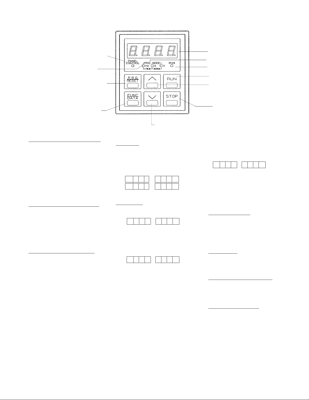
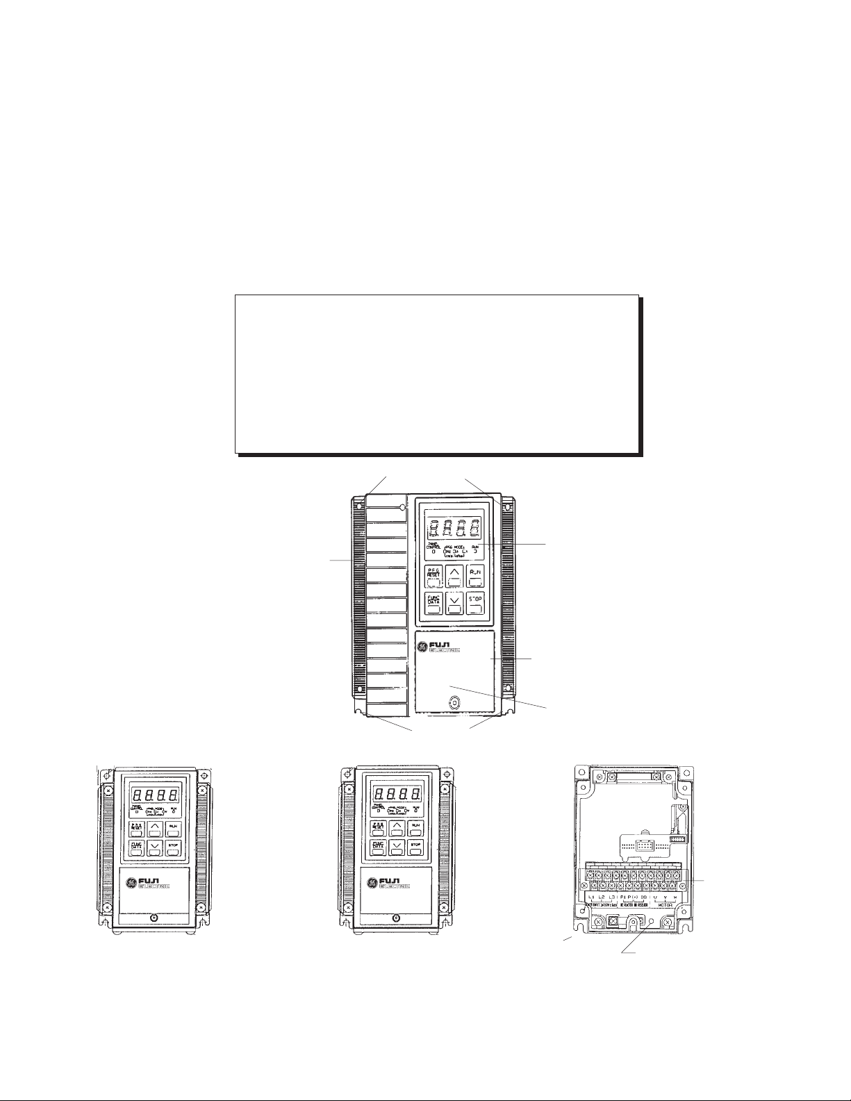
(1) Keypad Part Names and Functions
Operation Mode Indicator
Program Mode
Program/Reset Key
Function Key (Data Key)
Digital Display (4 digits) -
Displays the various Function
Codes and data values during
setting of the program. During
operation, it displays the output
frequency, current, voltage, etc.
If a fault occurs the cause of the
problem will be displayed as a
code.
PROGRAM Key (Reset Key) -
Normal mode or program setting
mode select key. When any of
the protection functions are
activated; this key is used to reset
the fault.
FUNCTION Key (Data Key) -
During the normal mode, this key
can be used to change the display
unit while operation is either
stopped or running.
During the program mode, this
key can be used to read and write
the Function Codes and the data.
DOWN Key
RUN Key - Key used for starting
operation. The LED (green) lights up
during operation.
This key does not function when
terminal operation control is selected.
F 0 2 = 1
or
F 0 2 = 2
STOP Key - This key is used for
stopping drive operation. When set
as follows:
F 0 2 = 0
operation command input is
accepted from the Keypad (RUN
and STOP keys).
When function 2 is set to 1:
F 0 2 = 1
Operation command input by
means of the external signal
terminal (FWD, REV). STOP key
on the keypad is active. If
selection "1" is chosen, and the
stop button is depressed while the
drive is running, the drive will
perform the normal stop
sequence until the output
frequency reaches zero at which
point an "Er6" fault shall be
indicated on the LED. To reset the
Digital Display
Unit Display
Drive RUN Indicator
RUN Key
UP Key
STOP Key
drive you must remove the RUN
command and press RESET.
When function 2 is set to 2:
F 0 2 = 2
operation command input is
accepted by means of the
external signal terminal (FWD,
REV). STOP key on the keypad
is inactive.
UP / DOWN Keys - These keys
increase or decrease the
frequency reference. When unit is
in program setting mode, they
change the Function Code or data
values.
Unit Display - Unit information is
displayed by the LED (red). All
three LEDs flash to indicate that
the unit is in the program mode.
Operation Mode Indicator -
The LED (green) lights up when
keypad panel operation is
selected.
Drive RUN Indicator -
The LED (green) lights up in the
RUN mode.
2-2
Page 11
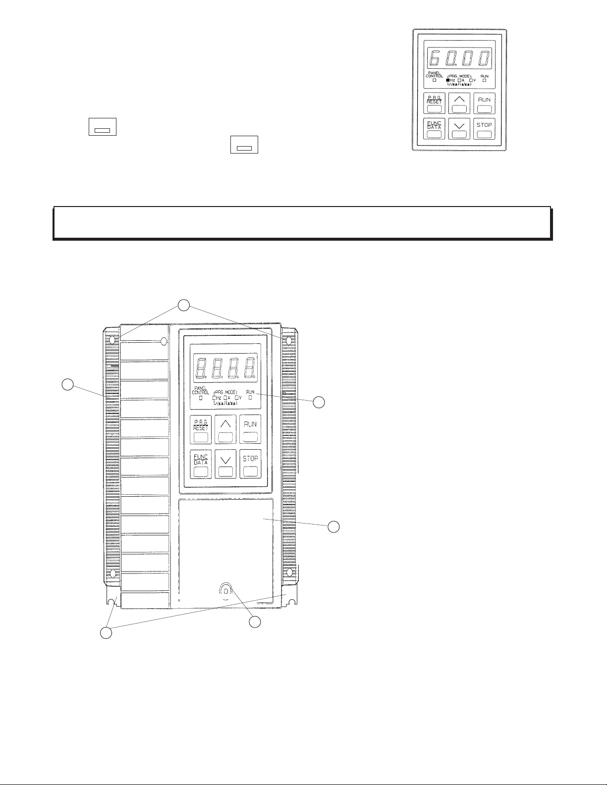
(2) Controlling Method for Keypad Panel
When the power supply is activated, the keypad panel display will be as shown
in the figure on the right (60.00 FLASHING).
RUN
If the key is pressed, the Drive will start and accelerate up to 60 Hz
according to the factory setting. Use the key to stop operation.
STOP
WARNING - RUN and STOP keys function only in Keypad operation mode. (Function Code F_02 setting is 0)
Drive Components
5
1
3
2
6
4
Figure 2-3. TYPICAL DRIVE COMPONENTS
1. Unit Cover (Middle)
2. Unit Cover (Top)
3. Keypad Panel (Optional)
4. Heat Sink and Mounting Tabs
5. Mounting Screw Holes
6. Top Cover Screw
NOTE: NEMA 1 unit does not include keypad. Keypad is sold separately.
Keypad type is 6KM$2KP1 for NEMA 1 unit.
2-3
Page 12

TABLE 1: Standard Specifications
ITEM
SPECIFICATION
Environmental Conditions
Enclosure NEMA 1or NEMA 4
Installation Location: NEMA 1 Suitable for indoor mounting only, less than 1000 meters (3281 feet) elevation,
not in contact with corrosive gas, oil mist, or dust.
NEMA 4
Stored Temperature -20° to +65°C (-4° to +149°F)
Ambient Temperature -10° to +50°C (+14° to +122°
Humidity 20% to 95% relative humidity (non-condensing)
Vibration 0.6G or less
Cooling Method 1/4 to 1 HP – Convection
Suitable for use indoors or outdoors to protect the enclosed equipment against
splashing water, seepage of water, falling or hose directed water and severe
external condensation. Installation should be less than 1000 meters (3281 feet)
elevation, not in contact with corrosive gas, or oil mist.
F) (remove ventilation covers if temperature is
over (+40°C +104° F)
2 HP and greater – Forced air (Integral fan)
Output
Rated Output Voltage 3-Phase, 3-Wire, 80-240 VAC or 160-480 VAC
(Can not exceed power supply voltage)
Frequency Range 0 - 400 Hertz (0.2 to 15 Hz Start Frequency; 15 to 400 Hz Base Frequency)
Above 120 Hz, contact the motor manufacturer for approval of application
Overload Current Rating 150% for 1 minute duration (inverse time characteristic)
200% for 0.5 seconds
Power Supply
Rated Input AC Voltage – 200 to 240 VAC 50/60 Hz, 1 phase (1/4 to 3 HP)
– 200 to 230 VAC 50/60 Hz, 3 phase (1/4 to 5 HP)
– 380 to 480 VAC 50/60 Hz, 3 phase (1/2 to 5 HP)
Voltage: +10% to -15%; Voltage Unbalance: Within 3%; Frequency ±5%
Control System Sinusoidal PWM "TORQUE VECTOR" Control
Control
Frequency Setting – Analog: 0.02 Hz step at Maximum frequency of 60 Hz
Resolution – Digital Keypad: 0.01 Hz Maximum frequency up to 99.99 Hz; 0.1 Hz (100
Hz or more)
Accuracy (Stability) Analog setting: ± 0.2% of Maximum frequency (59° to 95° F)
Digital Keypad setting: ± 0.01% of Maximum frequency (14° to 122° F)
2-4
Page 13

ITEM
SPECIFICATION
Control (continued)
Voltage/Frequency Voltage - 80-240 VAC or 160-480 VAC
Characteristics (V/F) Frequency - 0.2 to 400 Hz
Torque Boost 0: Automatic torque boost or 1 to 31.0 code settings (includes selection for
variable torque load)
Acceleration/Deceleration 0.01 to 3600 seconds (independent acceleration/deceleration)
Characteristics Alternative accel/decel time available as well as linear or 2 S-curves (selectable)
Motor Sound The pitch of the motor sound can be changed by selecting Carrier frequency
(F_12: 0 to 15)
Frequency Meter Adjustment Scale calibration of externally connected analog meter or pulse
frequency
Data Protection Data lock is possible to ensure that the function codes are not changed
High/Low Frequency Limiter Output frequency upper and lower range limit 0 to 400 Hz; 1 Hz step settings
Bias Magnitude of the zero offset can be set from 0 to ±100% of maximum
frequency (1Hz steps)
Gain Output frequency gain corresponding to the reference signal can be
set from 0 to 250%
15 Step Preset Speed 15 programmable preset speeds selectable by 4 contact closures
Maintained Contact Operation Maintained contact operation/stop command (2-wire operation)
Terminal Function Change Multi-Use terminal changed via Function Code settings (X4 input; Y1 output)
Operation
Frequency Reference Signal Speed potentiometer: 0 to +10 VDC 4 to 20 mA [(0 to +5VDC) gain adjust 0-250%]
Input Signal (contact type) Forward, reverse, multistep speed setting, alternate accel/decel time settings,
coast-to-stop, external alarm, 3-wire control and reset
External Output Signals One Dry Form "C" alarm output contact rated 250 VAC, 0.3 amp
1 – Open collector output rated 27 VDC, 50mA from external power
– Drive Run – FDT – FAR – LV– TL – Auto restart mode after momentary
power loss (IP)
Frequency Meter Output Signal Pulse frequency (adjustment to 6 kHz maximum)
Analog - 0 to +10 VDC (adjustment range of 6.5 to 10.3 VDC)
2-5
Page 14

ITEM SPECIFICATION
Operation (continued)
Protective Functions: – Stall prevention – Undervoltage
– Surge input – Overcurrent
– Drive overheating – Overvoltage
– External faults – Short circuit for output terminals
– CPU malfunction – Communication error
– Motor overload – Ground fault (at start)
(electronic thermal) – Output wiring not connected
– Memory error (during auto tuning only)
Keypad Digital Display - 4 digit LED
Drive Operation Output frequency, output current, output voltage, motor speed, line speed
(m/min), machine speed (r/min) can be displayed
Drive Setting Function Code and Setting Data can be displayed
Data Initializing Resets all Function Codes to initial factory settings
Drive Fault – OC1 - Acceleration overcurrent
– OC2 - Deceleration overcurrent
– OC3 - Constant speed overcurrent
– LU (LV) - Undervoltage
– OU1 - Overvoltage during acceleration
– OU2 - Overvoltage during deceleration
– OU3 - Overvoltage at constant speed
– OH1 - Drive overheat
– OH2 - External alarm input
– OLU - Electronic Overload - Semiconductor Overload Protection
– OL - Electronic Overload - 4 Pole Motor Overload Protection
– Er1 - Setting error
– Er2 - Communication error
– Er3 - CPU error
– Er4 - Optional circuit board communication error with Drive
– Er5 - Optional Problem - when a link error etc. is detected
– Er6 - Operating Proc. error
– Er7 - Output wiring error
Charge "CRG" Lamp (LED) Illuminates when DC Link capacitor voltage is present
2-6
Page 15
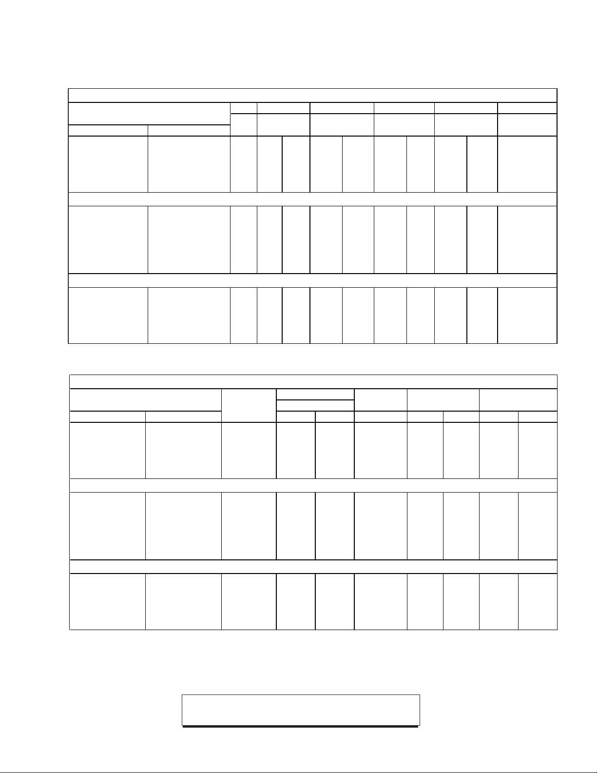
Table 2: Drive Dimensions
240 Volt – Single Phase
HP Weight Height Width Depth Dim. Figure
Model
Const LBS KGS Inches MM Inches MM Inches MM
Pages
NEMA 1 NEMA 4
TRQ
3-2 to 3-5
6KM$221F25N1A1 6KM$221F25X4A1 1/4 2.7 1.2 6.22 158 4.29 109 3.15 80 1 and 4
6KM$221F50N1A1 6KM$221F50X4A1 1/2 3.8 1.7 6.22 158 5.67 144 4.29 109 2 and 6
6KM$221001N1A1 6KM$221001X4A1 1 4.0 1.8 6.22 158 5.67 144 4.29 109 2 and 6
6KM$221002N1A1 6KM$221002X4A1 2 6.2 2.8 6.22 158 8.03 204 5.28 134 3 and 8
6KM$221003N1A1 6KM$221003X4A1 3 6.4 2.9 6.22 158 8.03 204 5.28 134 3 and 8
230 Volt – Three Phase
6KM$223F25N1A1 6KM$223F25X4A1 1/4 2.4 1.1 6.22 158 4.29 109 3.15 80 1 and 4
6KM$223F50N1A1 6KM$223F50X4A1 1/2 2.9 1.3 6.22 158 4.29 109 3.54 90 1 and 5
6KM$223001N1A1 6KM$223001X4A1 1 3.3 1.5 6.22 158 4.29 109 4.69 119 1 and 7
6KM$223002N1A1 6KM$223002X4A1 2 4.6 2.1 6.22 158 5.67 144 4.69 119 2 and 7
36KM$223003N1A1 6KM$223003X4A1 3 6.2 2.8 6.22 158 8.03 204 5.28 134 3 and 8
36KM$223005N1A1 6KM$223005X4A1 5 7.0 3.3 6.22 158 8.03 204 5.87 149 3 and 9
480 Volt – Three Phase
6KM$243F50N1A1 6KM$243F50X4A1 1/2 4.2 1.9 6.22 158 5.67 144 4.29 109 2 and 6
6KM$243001N1A1 6KM$243001X4A1 1 4.2 1.9 6.22 158 5.67 144 4.29 109 2 and 6
6KM$243002N1A1 6KM$243002X4A1 2 6.2 2.8 6.22 158 8.03 204 5.28 134 3 and 8
6KM$243003N1A1 6KM$243003X4A1 3 6.2 2.8 6.22 158 8.03 204 5.28 134 3 and 8
6KM$243005N1A1 6KM$243005X4A1 5 7 3.3 6.22 158 8.03 204 5.87 149 3 and 9
Table 3: Drive Rating Efficiency and Watts Loss Table
240 Volt – Single Phase
Output Current Output Efficiency
Model
NEMA 1 NEMA 4
6KM$221F25N1A1 6KM$221F25X4A1 1/4 1.5 1.3 0.19 87.6 80.9 27 45
6KM$221F50N1A1 6KM$221F50X4A1 1/2 3.0 2.5 0.37 88.1 83.2 50 75
6KM$221001N1A1 6KM$221001X4A1 1 5.0 4.0 0.75 90.4 88.8 80 95
6KM$221002N1A1 6KM$221002X4A1 2 8.0 7.0 1.50 92.9 91.5 115 140
6KM$221003N1A1 6KM$221003X4A1 3 11.0 10.0 2.20 93.6 92.4 150 180
Carrier Frequency
HP
Low High KW Low High Low High
230 Volt – Three Phase
6KM$223F25N1A1 6KM$223F25X4A1 1/4 1.5 1.3 0.20 87.6 80.9 27 45
6KM$223F50N1A1 6KM$223F50X4A1 1/2 3.0 2.5 0.40 88.1 83.2 50 75
6KM$223001N1A1 6KM$223001X4A1 1 5.0 4.0 0.75 90.4 88.8 80 95
6KM$223002N1A1 6KM$223002X4A1 2 8.0 7.0 1.50 92.9 91.5 115 140
36KM$223003N1A1 6KM$223003X4A1 3 11.0 10.0 2.20 93.6 92.4 150 180
36KM$223005N1A1 6KM$223005X4A1 5 17.0 16.5 3.70 94.6 93.4 212 260
6KM$243F50N1A1 6KM$243F50X4A1 1/2 1.6 1.4 0.37 86.0 79.9 60 93
6KM$243001N1A1 6KM$243001X4A1 1 2.5 2.1 0.75 90.4 86.9 80 113
6KM$243002N1A1 6KM$243002X4A1 2 3.7 3.7 1.50 93.2 88.1 110 203
6KM$243003N1A1 6KM$243003X4A1 3 5.5 5.3 2.20 94.4 89.4 130 260
6KM$243005N1A1 6KM$243005X4A1 5 9.0 8.7 3.70 94.9 91.0 200 366
NOTE:
Low setting F_12 = 0
480 Volt – Three Phase
Carrier Frequency: High setting F_12 = 15
2-7
Power Percentage
Watts Loss
Page 16
Section 3
➛
INSTALLATION GUIDELINES
INSTALLATION ENVIRONMENT
Install the Drive in an indoor location that meets the
following requirements:
— The ambient temperature is between -10° C and
+50° C (+14° F to +122° F). Remove the ventilation covers when the temperature exceeds +40° C
[+104° F].
— The relative humidity is between 20% and 95%.
Avoid any location subject to condensation, freezing,
or where the Drive would come in contact with water.
— Do not install in any location subject to direct sunlight,
dust, corrosive gas, inflammable gas, or oil mist.
— Vibration should be less than 0.6G.
— The Drive should be installed at an elevation below
1000 meters (3281 feet). For installation above 1000
meters (3300 feet) the Drive will need to be derated
1% per 333 feet.
Example: 5 HP, 460 VAC, output current 9 amps.
Application altitude 3900 feet.
3900 - 3300
% derate = x 1% = 1.8%
(9 amps) x = 8.84 amps
derated output current.
( )
333
100 - 1.8
( )
100
INSTALLATION MOUNTING
CLEARANCE
— Install at a sufficient distance from other equip-
ment, walls, or wiring ducts as shown in Figure
3-1 (these clearances are required to allow the
heat generated by the Drive to escape).
— Install the Drive perpendicular to the ground and
with the lettering right side up. (If the Drive is
installed upside-down or horizontally, heat buildup will occur.)
— Mounting screws or bolts should be of appropriate
size for weight of Drive.
— See the appropriate figures on pages 3-2 and
3-3 for the location of mounting holes.
— After removing the knockouts in the wiring lead-in
plate, install the rubber bushings supplied to prevent cable damage and to minimize dust entry.
CAUTION: The mounting wall for the Drive must be
constructed of heat resistant material because during
operation, the temperature of the Drive's cooling fins
rises to approximately 90 degrees C (194° F).
Motor derate may also be required,
contact motor manufacturer.
CAUTION: Because the ambient temperature greatly
affects Drive life and reliability, do not install the Drive in
any location that exceeds the allowable temperatures.
2"
or more
➛
5" or more
➛
➛
5" or more
➛
NOTE:
proximity, allow sufficient space as shown in Figure 3-1
and install them in a horizontal row. If they must be
installed in a vertical column, at least 19.7 inches (50cm)
internal space must be provided between each one or a
ventilation baffle should be provided to prevent the
ambient temperature from rising.
When installing two or more Drives in close
2"
or more
➛
Figure 3-1. DRIVE MOUNTING CLEARANCE
3-1
Page 17
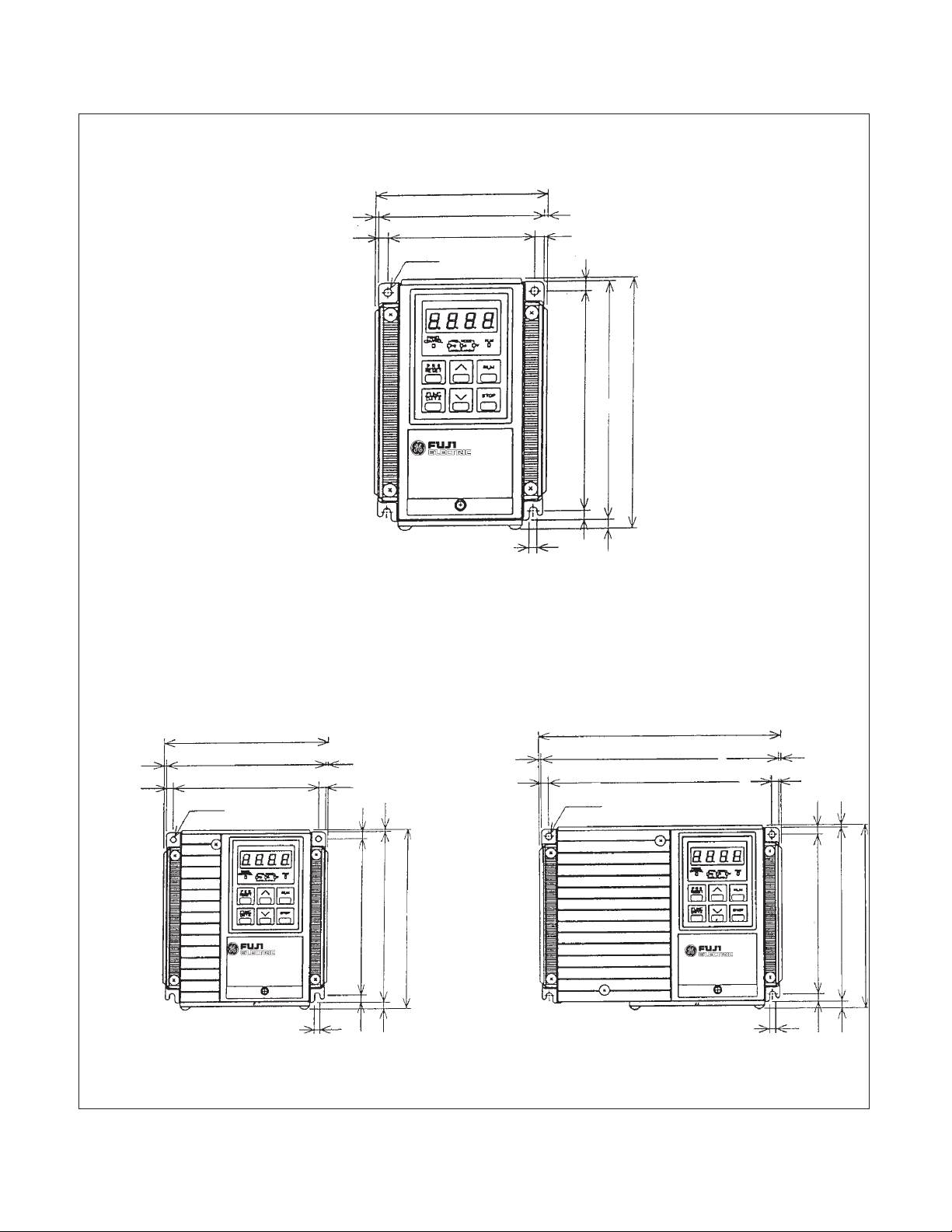
NOTE: NEMA 1 unit does not have Keypad.
Shown with optional Keypad
Dimensions
4.29 (109)
4.13 (105)
3.66 (93)
0.24 (6)
5.91 (150)
5.43 (138)
6.22 (158)
0.08 (2)
0.24 (6)
5.67 (144)
5.51 (140)
5.04 (128)
2-ø5 (0.20)
0.08 (2)
0.24 (6)
0.24 (6)
5.43 (138)
0.08 (2)
5.91 (150)
6.22 (158)
Figure 1
0.08 (2)
0.24 (6)
0.20 (5)
0.24 (6)
0.24 (6)
0.20 (2-ø5)
8.03 (204)
7.87 (200)
7.40 (188)
0.08 (2)
0.24 (6)
0.08 (2)
0.24(6)
5.43 (138)
5.91 (150)
6.22 (158)
0.20 (5)
0.24 (6)
0.24 (6)
Figure 2 Figure 3
Note: Inches (MM)
3-2
0.20 (5)
0.24 (6)
0.24 (6)
Page 18
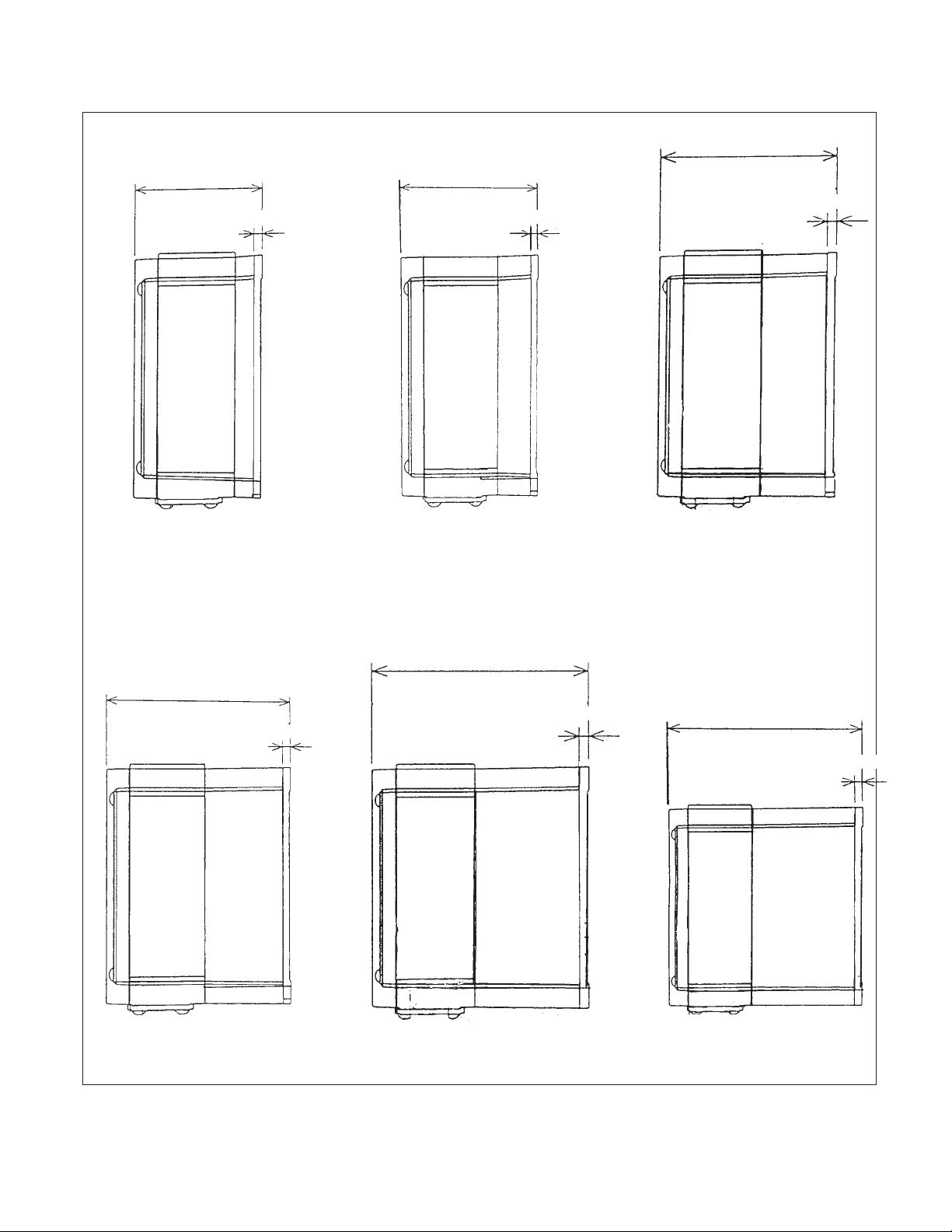
Dimensions
4.29 (109)
3.15 (80)
0.20 (5)
3.54 (90)
0.20 (5)
Figure 4 Figure 5 Figure 6
0.24 (6)
5.28 (134)
4.69 (119)
0.24 (6)
0.24 (6)
Figure 7 Figure 8 Figure 9
Note: Inches (MM)
5.87 (149)
0.24 (6)
3-3
Page 19
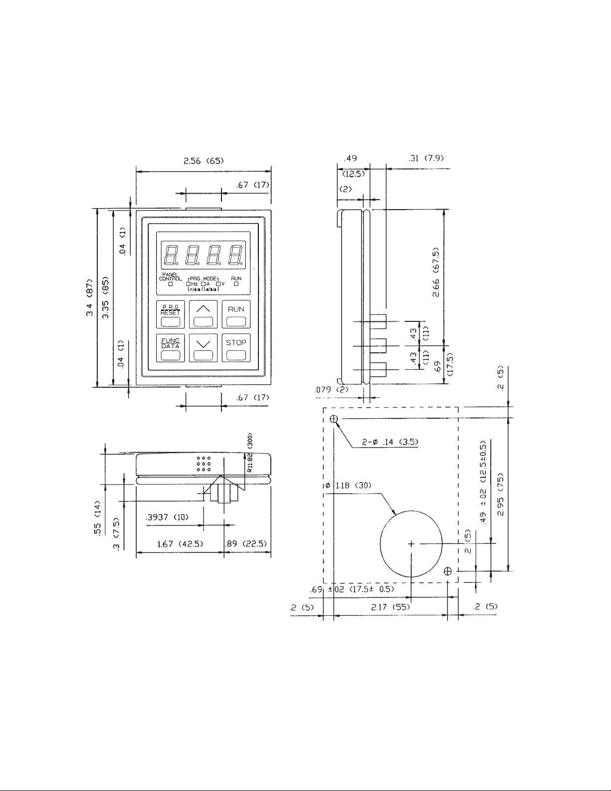
Dimensions of Keypad and Keypad Mounting Holes
Keypad Part # 6KM$2KP1 for NEMA 1 unit
6KM$2KP4 for NEMA 4 unit
3-4
Mounting Hole (panel cut-out)
Inches (MM)
Page 20
Section 4
WIRING PROCEDURES
To access Main and Control Circuit Terminals remove the top
cover as follows (see Figure 4-1):
1. Loosen the screw located at the bottom of the top cover.
2. Press upward on the bottom of the top cover (see arrows
Figure 4-1 step 2) and lift off.
3. See Figure 4-1 for the location of the Main Circuit
Terminal Block and the Control Circuit Terminal Block.
WARNING: Some printed circuit boards and Drive components may contain hazardous voltage levels. If LED
light "CRG" on the Base Driver Board is illuminated,
hazardous voltages are present in the Drive circuit boards.
Remove and lock out power before you disconnect or
reconnect wires, and before you remove or replace fuses
and circuit boards. Do not attempt to service the Drive
until the "CRG" indicator has extinguished and the bus
voltage has discharged to zero volts.
Removing T op Cover
Mounting Screw
Holes
Step 1:
Loosen Top Cover
screw. (1 to 2 turns)
Unit Cover (Middle)
Step 2:
Press Upward at the locations indi-
cated by the arrows to remove the top
cover.
and Mounting Tabs
→
Heat Sink
→
Keypad Panel
Unit Cover (Top)
Top Cover Screw
Main Circuit
Teminal Block
Control
Circuit
Terminal
Block
Drive
Charge "CRG" Lamp
Figure 4-1. REMOVING THE TOP COVER
4-1
Page 21
Control Circuit Wiring
Drive is wired at shipment for operation and frequency
setting through the keypad panel (frequency is set at 60
Hz.)
– See Figure 4-2, and 4-4 for wiring connections.
– See TABLE 5 for description of all terminals.
Make wire connections as shown in Figure 4-4 through 4-6
for desired mode of external operation through Control
Circuit Terminals.
CAUTION: The Control Circuit Terminal wiring should be
kept as far away as possible from the main power wiring to
prevent operational error due to noise interference. Never
install both types of wiring in the same duct or conduit. (A
separation distance of 4 inches [10 centimeters] or more is
recommended.) If the control circuit wiring must cross the
main power wiring, it should cross at a right angle.
CAUTION: Use shielded or twisted wire for the control
circuit wiring (wiring should be as short as possible, i.e. 65
feet or less [20 meters.]) Connect outer covering of the
shielded wires to the Drive ground terminal and leave the
other end open, but taped with electrical insulating tape.
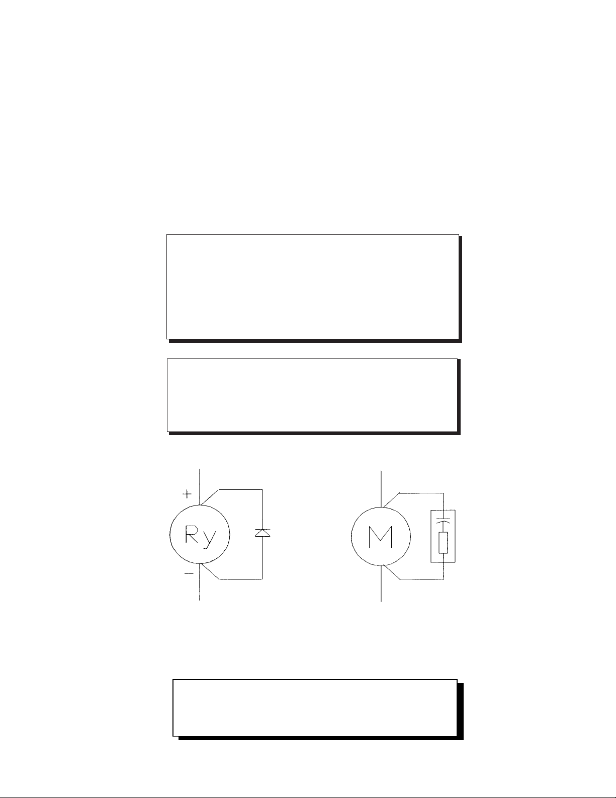
DC RELAY
Figure 4-2. CONNECTION OF SURGE SUPPRESSION DEVICES
AC CONTACTOR
CAUTION: Install a suppressor in parallel with any relay or
solenoid type coil as shown above, that may be close to the
Drive to prevent noise from causing erratic Drive operation.
4-2
Page 22
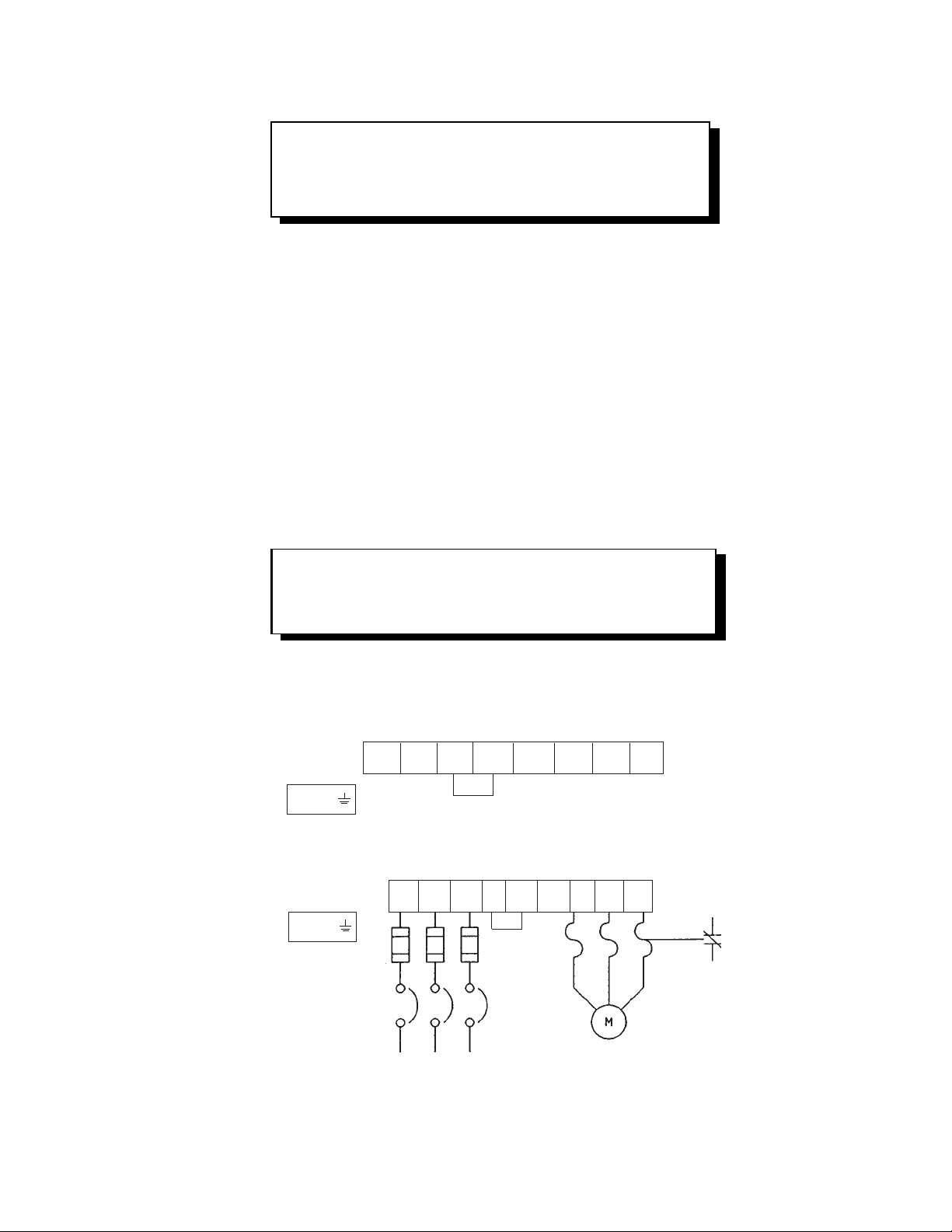
Main Circuit Wiring
CAUTION: Be sure that the power supply is never
connected to the U, V, W terminals or the P (1), P (+),
DB terminals.
1. Connect the ground terminal as shown in the appropriate view of Figure 4-3. (Do not operate without
the unit being grounded.)
— The ground wire must be minimum 14 AWG
and short as possible
2. Connect the power supply wires to the L1, L2, and
L3 terminals of the Main Circuit Terminal Block as
shown in the appropriate view of Figure 4-3. (See
TABLE 5 for description of all terminals and TABLE
4 for recommended wire sizes.) Note that L1 and L2
terminals only, are available on single phase input
models.
NOTE:
the shaft end when connected normally. If the motor rotates in
reverse direction, interchange any two of the U, V, or W terminal
connections.
Motor will rotate counterclockwise when viewed from
3. Connect the 3-phase motor wires to the U, V, and
W terminals of the Main Circuit Terminal Block as
shown in the appropriate view of Figure 4-3. (See
TABLE 5 for description of all terminals and TABLE
4 for recommended wire sizes.)
4. Suitable for use on a circuit capable of delivering not
more than 1000A (1 HP or less) or 5000A (2 HP or
more) RMS symmetrical.
5. AC input fuses are to be customer supplied and may
be branch circuit protection fuses. The maximum
allowance fuse rating per TABLE 4.
240V – Single Phase 1/4 to 3 HP
L1 L2 P1 P(+) DB* U V W
E (G)
230 & 480V – Three Phase 1/4 to 5 HP
L1 L2 L3 P1 P(+) DB U V W
E (G)
Fuses: Rating per TABLE 4
Reference UL power circuit
protection requirements.
CB
50/60 Hz, 3–Phase AC
✟ Factory installed jumper (Remove when installing DC Reactor)
* The DB resistor connection is not available on models 6KM$221F25X1A1,
6KM$221F25A4A1, 6KM$223F25X1A1, 6KM$223F25A4A1.
# Optional
Figure 4-3. MAIN CIRCUIT TERMINAL LAYOUT
✟
✟
Thermal Relay
3–Phase Motor
#
4-3
Page 23
Table 4:
ing
lly
Wire Size Recommendations
& Circuit Protection Ratings
240V – Single Phase and 230V Three Phase
DB Incoming Power
Model PH HP Output Current Power Resistor** AC – Line Devices
NEMA 1 NEMA 4
6KM$221F25N1A1 6KM$221F25X4A1 1 1/4 1.5 1.3 16 - 6 5
6KM$221F50N1A1 6KM$221F50X4A1 1 1/2 3 2.5 16 16 10 10
6KM$221001N1A1 6KM$221001X4A1 1 1 5 4 14 14 15 15
6KM$221002N1A1 6KM$221002X4A1 1 2 8 7 12 12 20 20
6KM$221003N1A1 6KM$221003X4A1 1 3 11 10 10 10 30 30
6KM$223F25N1A1 6KM$223F25X4A1 3 1/4 1.5 1.3 16 - 6 5
6KM$223F50N1A1 6KM$223F50X4A1 3 1/2 3 2.5 16 16 10 5
6KM$223001N1A1 6KM$223001X4A1 3 1 5 4 16 16 15 10
6KM$223002N1A1 6KM$223002X4A1 3 2 8 7 14 14 20 15
6KM$223003N1A1 6KM$223003X4A1 3 3 11 10 14 14 30 20
6KM$223005N1A1 6KM$223005X4A1 3 5 17 16.5 10 10 40 30
480V – Three Phase
Model PH HP Output Current Power Resistor** AC – Line Devices
NEMA 1 NEMA 4
6KM$243F50N1A1 6KM$243F50X4A1 3 1/2 1.6 1.4 16 14 6 5
6KM$243001N1A1 6KM$243001X4A1 3 1 2.5 2.1 16 14 6 5
6KM$243002N1A1 6KM$243002X4A1 3 2 3.7 3.7 16 14 15 10
6KM$243003N1A1 6KM$243003X4A1 3 3 5.5 5.3 16 14 15 15
6KM$243005N1A1 6KM$243005X4A1 3 5 9.0 8.7 14 14 20 15
Const
Input TRQ Low High AWG AWG Fuses* Breaker
Const
Input TRQ Low High AWG AWG Fuses* Breaker
Carrier Frequency
Carrier Frequency
Wire Wire Circuit
DB Incoming Power
Wire Wire Circuit
WARNING - Device ratings such as system coordination, short-circuit
rat
and type must be carefu
NOTE:
75° C for over 100 amps in 30° C ambient and 1.25 times Drive rated amps. These
are minimum wire sizes; consult and conform to local and national codes.
*NOTE: AC input fuses are required to validate the drive's UL and CSA approvals.
** Optional Item.
Wire size from NEC table 310-16. Copper wire rated 60° C for 100 amps or less,
The fuse should be Class J type such as Bussman, JKS or equivalent. Circuit breaker
ratings are shown for reference, but UL and CSA approval can only be validated by
the use of Class J fuses.
reviewed by the user.
4-4
Page 24
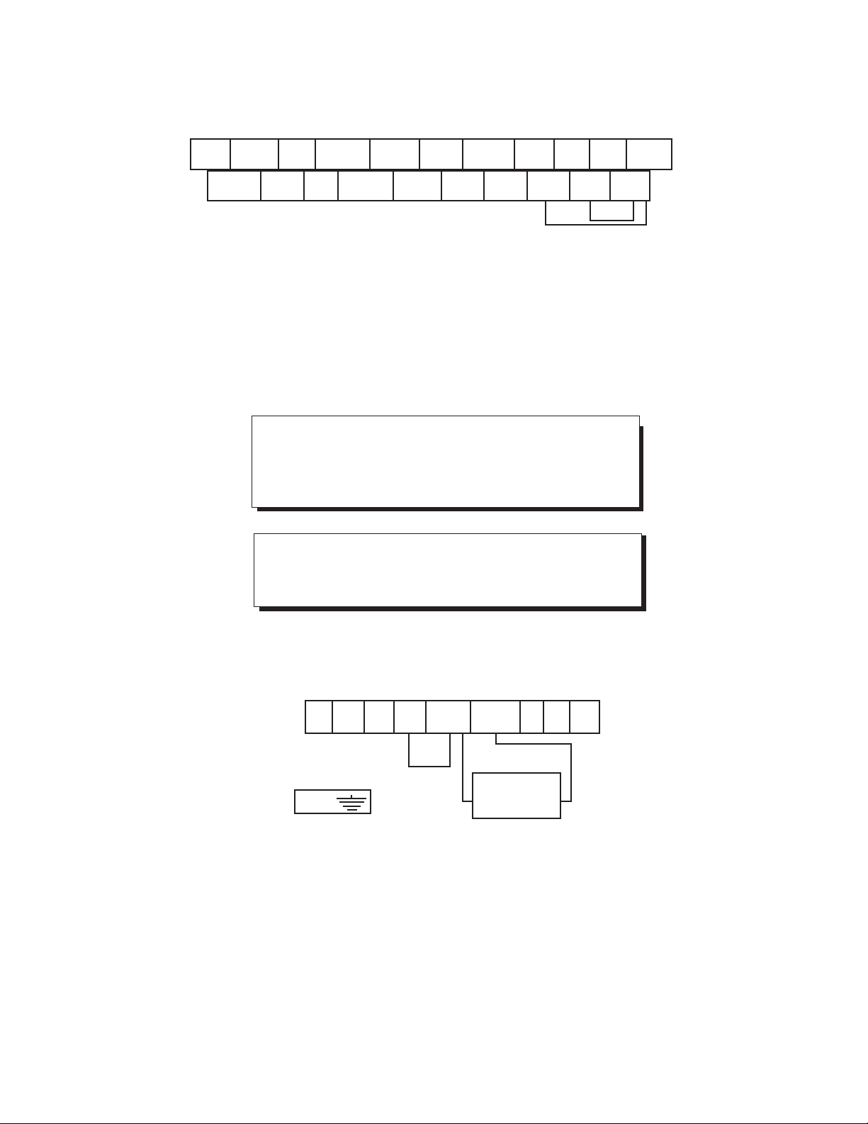
30A 30B Y1 FMA PLC BX RST C1 13 12 11
30C FMP X1 X2 X3 X4 REV FWD THR CM
#1
*
* Factory installed jumper
*
CONTROL CIRCUIT TERMINAL BLOCK LAYOUT
#1 CAUTION:
Remove jumper from between terminals THR and CM when
a motor overload or a motor temperature switch is used.
Wire the device thermal switch in series with the THR and
CM terminals.
#2 NOTE:
FWD to CM jumper required for operation using keypad
RUN-STOP.
#2
Figure 4-4.
L1 L2 L3 P1 P(+) DB* U V W
DB
E(G)
* Not available on 6KM$221F25X1A1, 6KM$221F25A4A1, 6KM$223F25X1A1, 6KM$223F25A4A1.
Figure 4-5. DYNAMIC BRAKING RESISTOR CONNECTIONS
RESISTOR
4-5
Page 25
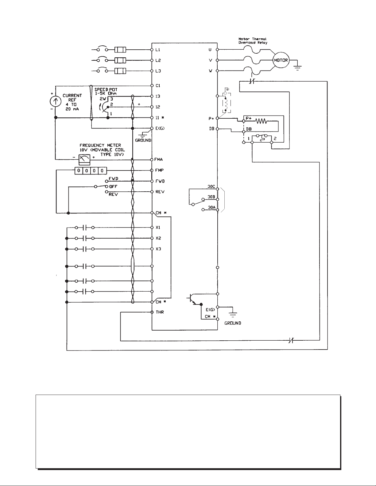
1 or 3PH
50/60 Hz
230/480 Vac
(Based on
Model selected)
DIGITAL METER
DISCONNECT/
CIRCUIT
BREAKER #
FUSE
✟
DO NOT CONNECT
TO CM
DC REACTOR #
P1
BRAKING RESISTOR
1/2 TO 5HP #
BRAKING RESISTOR
THERMAL SWITCH
ALARM RELAY OUTPUT
#
GROUND
BX
RST
X4(HLD)
PROGRAMMABLE LOGIC
PLC
CONTROL POWER
Y1
ANY ADDITIONAL NORMALLY
CLOSED PROTECTIVE
INTERLOCKS SHOULD BE
ADDED IN SERIES
* Terminal 11 should not be connected to CM.
✟ L3 not supplied on single phase units.
# Optional
Figure 4-6. WIRING DIAGRAM
CAUTION:
1. The Control Circuit Terminal wiring should be kept as far as possible from the main circuit wiring to prevent
operation error due to noise interference. Never install them in the same duct or conduit. A separation distance
of 4 inches or more is recommended. If the control circuit wiring must cross the main circuit wiring, make sure
it crosses at a right angle.
2. Use shielded wire for the control circuit wiring, which should be as short as possible (66 feet or less). Connect
shield to the Drive ground terminal and leave the other end open but taped.
3. Install a surge protector in parallel with any magnetic contactors, solenoids, relays or timer coils which are close
to the Drive.
4-6
Page 26

TABLE 5: Terminal Identification/Function
Terminal Terminal
Label Name Function
POWER TERMINAL BOARD
L1, L2, AC Supply Line Connection for 200-230 VAC or 380-480 VAC, 3-phase, 50/60 Hz;
L3 Input Terminals L1 & L2 for single phase input, 200-240 VAC 50/60 Hz
U, V, W Drive Output Connection for 3-phase induction motor
Terminals
P+, DB External Braking Connection for external braking resistor option for single phase and
Resistor Terminals three phase drives (Only on 1⁄2 HP to 5 HP; not on 1/4 HP)
P1, P+ DC Reactor Terminals Connection for external DC reactor for power factor improvement
(Option). (Remove factory installed jumper)
CONTROL TERMINAL BOARD
11 Frequency Setting & Common connector for terminals 12, 13, C1 and FMA (Do not
Analog Freq. Meter connect to CM terminal or electrical noise immunity may be lost).
Common Terminal
12 Frequency Setting When 0 to +10 VDC (0 to 5V*) is applied, the maximum frequency is
Voltage Input reached at +10 VDC (5V*) and is proportional to output frequency
down to 0 VDC. Input impedance is 22K ohm ( *250% gain setting F_35)
13 Frequency Setting Regulated +10 VDC power supply for frequency setting potentiometer,
Voltage Output Term. 10mA or less (13 to terminal 11)
C1 Frequency Setting When the input signal is +4 to +20mA dc, the maximum frequency is
Current Input (+) reached at 20mA and is proportional down to a minimum frequency
setting at 4mA. Input impedance is 250 ohm, must be isolated source
CM Control Circuit Common terminal for control input commands, X1-X4, FWD, REV, BX,
Common Terminal RST, THR, Y1 and FMP pulse output signal
(Do not connect to terminal 11)
FWD Forward Command
Input Terminal Forward command via FWD-CM (closed). Reverse command via
REV-CM (closed). When FWD-CM and REV-CM are closed
Reverse Command at the same time, the Drive will decelerate to stop
REV Input Terminal
BX Motor Coast-To-Stop Motor will coast-to-stop with BX-CM (closed). (For use when
Command Input applying mechanical brake with Drive in operation.) Note: If BX-CM is
Terminal opened with FWD or REV closed, the Drive will start the motor
RST Fault Reset Input After removal of fault condition, Faults are reset when a momentary
Terminal contact closure is made between the RST-CM terminals for more
than 0.1 seconds
If there is an input to the FWD or REV terminals with F_02 = 1 OR
2 and F_14 = 4 or 5 the Drive will suddenly restart.
4-7
Page 27

TABLE 5: Terminal Identification/Function (continued)
Terminal Terminal
Label Name Function
CONTROL TERMINAL BOARD (Continued)
THR External thermal trip With THR-CM (open), OH trip will occur and the motor will
command coast-to-stop.
NOTE:
thermostat, the THR-CM terminals must be closed or the Drive
will not operate. THR-CM is factory pre-jumpered, remove prior to
connecting an external NC contacts.
FMA* Analog Frequency Provides an output of 0 to +10 VDC (+10VDC at max frequency),
Meter Connection available for connection of a voltmeter with internal resistance of
F_40=0 10K ohms. See Function Code 41 for monitoring selection. Meter
connects between terminal FMA & 11. Note: FMP cannot be used
FMP* Digital Frequency Pulse frequency output equal to Drive output frequency.
Meter Connection Pulse voltage: Peak 5 VDC, 50% duty, Adjustable range = 600 to
F_40=1 6000 Hz (Max) See Function Code 42 Pulse Rate Multiplier.
Meter connects between FMP and CM. Note: FMA cannot be used
With no external thermal relay or external braking resistor
30A Fault Relay Output During normal operation, the relay is not energized and contact is made
30B Terminals between 30B and 30C. When a fault is detected, the relay is energized
30C and contact is made between 30A and 30C. (Contact rating resistive
load: 250 VAC, 0.3 Amps)
X1-X3 Multistep Frequency Seven individual preset frequency selections via binary combination
Input Function (closure) between X1, X2, X3, and CM.
Selection Frequency selections determined using functions F_21 thru F_27.
X4 Function Extension F_43=0 acceleration/deceleration time #2 is selected when X4-CM is
(Input) closed. When not closed #1 setting is activated.
(F_43=1) 8 additional frequencies can be selected by X1, X2, X3 and X4.
(F_43=2) 2nd Motor selection when X4 - CM is closed.
(F_43=3) Functions as hold signal if 3-wire operation is desired.
Y1 Output Function Outputs one of the following signals depending on setting of F_54;
(Programmable) 0: Drive running (RUN) 3: Undervoltage stop mode (LV)
1: Frequency level detection (FDT) 4: Torque limiting mode (TL)
2: Frequency equivalence (FAR) 5: Auto restart mode after
momentary power loss (IP)
Allowable load: Maximum 27VDC, 50mA or less
PLC PLC Prevents PLC fault caused by leakage current from the drive. (See Drive
interface details, Figure 4-7)
* Either an analog (FMA) or digital (FMP) frequency meter, not both.
4-8
Page 28

Output Terminal Y1
CM
Drive Interface Details
27 Vdc MAX Load
50 mA MAX
Y1
Input Terminal FWD, REV, X1-X4, BX, RST, THR
DC24 - 27V
6 mA MAX
Input Terminal
22K Ohms
250 Ohms
CM
Reference Input
1 - 5K Ohms
2 WATT
+4 to +20 mA dc
With PLC Terminal Connection Between PLC and Drive
PLC Drive
Note: Do Not
Connect
Figure 4-7. DRIVE INTERFACE DETAILS
4-9
Page 29

Section 5
DRIVE OPERATION
PRE-OPERATION INSPECTION
After mounting and wiring has been completed, check the Drive for the following items before applying AC power:
— Check for wiring errors.
— Verify that there are no wiring chips, screws, etc. remaining in the Drive.
— Check that all screw and terminal connections are tight.
— Verify that no exposed wire ends are touching other terminals.
KEYPAD PANEL IDENTIFICATION / OPERATION
See the following diagrams for Display and Keypad Operation description when in the Operation Mode, Program
Mode or Trip Mode.
FUNCTION CODE AND DATA CODE DESCRIPTION / SELECTION
When AC power is applied to the Drive, the keypad panel display will be as shown in Figure 5-1 and will be
flashing on and off. If the RUN key is pressed at this point, operation will be at 60 Hertz according to the
Function Code set at the factory. (Use the STOP key to halt operation.)
-- A Flashing display indicates when a run command is not present.
-- A Solid display indicates the actual output when the Drive is running.
If a test run is desired, press the key to change the flashing display of 60.00 Hz frequency setting to
5.00 Hz. Press RUN to conduct the test run and check for smooth motor operation and direction of rotation.
Removal of AC power will store a frequency reference in memory.
Figure 5-1. KEYPAD PANEL DISPLAY WHEN AC POWER IS APPLIED
5-1
Page 30

Keypad and Display Operation Programming
Mode Selection
The Drive has five (5) modes as shown below. The mode can be changed with the keys on the keypad panel.
(1) Stop Mode: Drive stopped (4) Program Mode: Motor Running
(2) Run Mode: Drive operational (5) Trip Mode: Drive system faults
(3) Program Mode: Motor Stopped
Data Setting
Changing Function Codes in the STOP Mode
➀
Stop mode
PRG
RESET
FUNC
DATA
1
Stop Mode
3
All Function Codes
Can Be Changed
2
Run Mode
5
Trip Mode
PRG
RESET
PRG
RESET
4
Restricted Function
Code Access
RUN
PRG
RESET
This is the state in which all operation signals ( signal)
[Keypad operation], FWD and REV signals (Terminal operation)
are OFF.
The last keypad display (frequency, amps, volts etc.) flashes
repeatedly.
The mode is switched to Function Code setting mode (All
Function Code settings can be changed).
Each time the key is pressed, the display changes between
indication of a Function Code and its data.
When these keys are pressed while the Function Code is displayed, the Function Code number will change. By pressing
them while data is displayed, the data can be changed.
FUNC
DATA
The data is stored and the Function Code advances to the next
Function Code number.
Are
there any
more functions
To change other data, repeat the above procedure.
to change?
PRG
RESET
Changing Function Codes in the RUN Mode (See TABLE 6)
➁
The program mode is ended and the Drive returns to STOP
mode.
5-2
Page 31

Display and Key Operation
1. Operations and displays in each mode
The keypad panel modes can generally be classified into five types. The operation method and the display
contents of each mode are shown below.
NOTE:
STOP Mode (Display continually flashes)
➀
Hz display
Following examples are with maximum frequency, F_03 set higher than 60 Hz
A display
FUNC
DATA
➛➛
PRG
Reset
To PROGRAM
mode while stopped
➛
➛
PRG
Reset
To PROGRAM
mode while stopped
➛
➛
FUNC
DATA
➛
FUNC
DATA
r/min display
PRG
Reset
To PROGRAM
mode while stopped
➛
FUNC
DATA
V display
PRG
Reset
To PROGRAM
mode while stopped
➛
➛➛
m/min display
➛
PRG
Reset
➛
➛
To PROGRAM
mode while stopped
➛
RUN
Keypad panel
operation:
➛➛
Drive will run
Display = Hz
Terminal operation:
Not operational.
STOP
➛
➛
RUN
Terminal operation:
Not operational.
STOP
Not effectiveNot effective
Keypad panel
operation:
Drive will run
Display = A
➛
RUN
Keypad panel
➛
STOP STOP
operation:
Drive will run
Display = V
Terminal operation:
Not operational.
Not effective
➛➛
5-3
RUN
➛
Keypad panel
➛
operation:
Drive will run
Display = r/min
Terminal operation:
Not operational.
Not effective
➛
➛
RUN
Keypad panel
➛
Drive will run
Display = m/min
Terminal operation:
Not operational.
STOP
Not effective
➛
operation:
Page 32

RUN Mode
➁
Hz display A display
FUNC
DATA
➛
PRG
*
Reset
PROGRAM Mode
while running
➛
➛
PRG
Reset
PROGRAM Mode
➛
➛
FUNC
DATA
➛
while running
V display
PRG
Reset
PROGRAM Mode
➛
➛
FUNC
DATA
➛
while running
r/min display
PRG
Reset
PROGRAM Mode
while running
➛
➛
FUNC
DATA
➛
m/min display
PRG
Reset
PROGRAM Mode
while running
➛
➛
➛
RUN
➛
Keypad panel
operation:
Drive will stop
➛
STOP
Display = Hz
Terminal operation:
F_02=1 Drive will stop
LED will show Er6
F_02=2 Stop key not
operational
➛
RUN
Not effectiveNot effective
➛
Keypad panel
Drive will stop
➛
STOP
Display = A
Terminal operation:
F_02=1 Drive will stop
LED will show Er6
F_02=2 Stop key not
operation:
operational
➛ ➛
RUN
Not effective
➛
Keypad panel
operation:
Drive will stop
➛
STOP STOP
Display = V
Terminal operation:
F_02=1 Drive will stop
LED will show Er6
F_02=2 Stop key not
operational
➛
RUN
Not effective
➛
Keypad panel
operation:
Drive will stop
➛
Display = r/min
Terminal operation:
F_02=1 Drive will stop
LED will show Er6
F_02=2 Stop key not
operational
* NOTE: See TABLE 6 (page 5-12) for Functions that can be changed while in RUN Mode.
RUN
Not effective
➛
Keypad panel
operation:
Drive will stop
➛
STOP
Display = m/min
Terminal operation:
F_02=1 Drive will stop
LED will show Er6
F_02=2 Stop key not
operational
5-4
Page 33

PROGRAM mode while stopped (example: changing the Torque Boost 1data)
➂
➛
➛
➛
FUNC
DATA
Data is Stored*
FUNC
DATA
➛
➛
PRG
Reset
Exit PROGRAM mode
➛
to keypad display**
RUN
Not effective
➛
STOP
Not operational
➛
FUNC
DATA
➛
PRG
Reset
Exit PROGRAM mode
➛
to keypad display**
RUN
Not effective
➛
STOP
Not operational
➛
Data is Stored*
FUNC
DATA
Data is Stored*
➛
➛
→
*NOTE: After changing function data with keys, the key must be pressed. If this is not
done, the data will not be stored. If the key is pressed before key is pressed, the
PRG
Reset
FUNC
DATA
FUNC
DATA
changed data will be canceled and operation will continue with the previous data.
* * NOTE: Keypad displays Frequency, Amps, Voltage, etc. based on selection.
5-5
Page 34

PROGRAM mode while running (example: changing the Torque Boost 1data)
➃
*NOTE: After changing function data with keys, the key must be pressed. If this is not done,
the data will not be stored. If the key is pressed before key is pressed, the changed data
PRG
Reset
FUNC
DATA
FUNC
DATA
will be canceled and operation will continue with the previous data.
* * NOTE: Keypad displays Frequency, Amps, Voltage, etc. based on selection.
See Table 6 for Functions that can be changed while in RUN mode.
5-6
Page 35

TRIP mode
➄
NOTE: Past fault records also can be displayed with Function Code 29.
Display of
present fault
status
PRG
Reset
Resets Fault
➛
Not effective
➛
Display of
previous fault
status
PRG
Reset
Resets Fault
➛
Display of
second- to-last
fault status
PRG
Reset
Resets Fault
➛
Display of
third-to-last
fault status
PRG
Reset
➛
Resets Fault
MECHANICAL MOTION
HAZARD: If there is an input to the FWD-CM or REV-CM
with F_02 = 1 or 2 and F_14 + 4 or 5 (Terminal
Mode) the Drive will suddenly restart.
END
PRG
Reset
➛
➛
Resets Fault
Not effective
FUNC
DATA
➛
➛
STOP
Not effective
➛
Not effective
Not effective
FUNC
DATA
Not effective
➛
Not effective
➛
STOP
Not effective Not effective
➛
FUNC
DATA
➛
➛
STOP STOP STOP
➛
Not effective
Not effective
FUNC
DATA
Not effective
➛
RUNRUNRUNRUN
Not effective
➛
Not effective Not effective
➛
FUNC
DATA
RUN
➛
➛
➛
Not effective
Not effective
5-7
Page 36

PROGRAM Mode PROGRAM Mode
Keys and Indicators Mode STOP Mode RUN Mode While Stopped While Running TRIP Mode
Function Display output frequency, current, Display function codes and data Display fault status
voltage, motor speed or line speed and fault memory listing
Indication Repeated Flashing Lit
Function Unit display for output frequency, current, Indicates PROGRAM mode None
voltage, motor speed or line speed
Indication Not Lit
PANEL
Function Indicates whether Keypad Panel or Terminal Operation Selected None
CONTROL
Indication Lit during Keypad Panel Operation Lit
Function Indicates Stopped Indicates Running Indicates Stopped Indicates Running Indicates Fault
Indication Not Lit Lit Not Lit Lit Not Lit
Function Program Mode Program Mode Stop Mode Run Mode Indicates Fault
Switches Digital Monitor & LED's
•
Change Display between Function Code and data
Function Unit indicates displayed values
•
Data setting and incrementing Function Code
Not Effective
•
Stores data and renews Function Code
Increases and decreases Increases and Increases and decreases
Function frequency, motor speed decreases Function Function Codes Displays Fault Memory
or line speed settings Codes and data and Data (stores data
values. temporarily)
Function Change to Run Mode Not Effective
Change to
Change to Program
Function Not Effective Stop Mode Not Effective Mode while Stopped Not Effective
(F_02 = 0)
(F_02=0)
Summary of each operation mode : The following table shows a summary of the various modes.
Lit
Repeated Flashing
Lit
Repeated Flashing
PRG. MODE
Hz A V
r /min m /min
PRG. MODE
Hz A V
r /min m /min
Change to
Stop Mode or 1
(F_02=0) or
(F_02=1)
PRG. MODE
Hz A V
r /min m /min
5-8
RUN
PRG
RESET
FUNC
DATA
RUN
STOP
Page 37

Operation
Pre-Operation Inspection
After completion of installation and wiring work, inspect the following items before the power supply to the Drive is
switched on.
CAUTION:
1. Check for wiring errors. (Especially the main circuit wiring: connection of the three
(single) phase AC power supply to the terminals L1, L2, L3 (L1, L2)).
2. Check that all loose wire strands, metal chips and unnecessary screws, etc. have been removed.
3. Check that all screws, terminals, and components are tight.
4. Check that the wire ends of crimp terminals are not in contact with other terminals.
CAUTION: Megger Test:
Do not conduct megger tests between the Drive main circuit terminals, or control circuit terminals.
Refer to Section 7 "Maintenance and Inspection."
Test Run Check Points
Use a low frequency reference setting of about 5 Hz to test Drive operation.
The following operating conditions must be confirmed:
1. Smooth motor rotation.
2. Correct direction of equipment rotation.
3. No abnormal vibrations and noise from the motor over full speed range.
4. Smooth acceleration and deceleration over full speed range.
Selecting Operation Method
The following methods can be selected to input the RUN/STOP signals and for frequency setting.
Keys
Analog signal (4 to 20 mA dc)
RUN
STOP Keys
*3
or
or (0 to 10Vdc)
Keys
Analog signal (4 to 20 mA dc)
or (0 to 10Vdc)
2
NOTES:
*1: F_02 cannot be changed when there is a short circuit (jumper)between either FWD-CM or REV-CM.
*2: Multistep speed operation (up to 8 steps are possible)
The frequencies of step 1 to step 7 are set with the Function Codes F_21 to F_27 and selected
with the terminals X1, X2 and X3 (Additional 8 steps available with F_43 = 1 and F_44 to F_51
using X4).
If input signals are provided to terminals X1, X2 and X3, then data setting of F_01 (settings made by
keypad panel or analog signal are ignored) and multistep speed operation is controlled by these
terminal signals.
*3: F_02 =1 Stop key on the keypad active
F_02 = 2 Stop key on the keypad inactive
5-9
Page 38

TABLE 6: Function Codes
Function Code Numbers Followed by Function Descriptions
* Function can be changed while the Drive is operating.
Basic Functions
–
00 Data Protection 1
01 Frequency Command 1
02 Operation Command 3
03 Maximum Frequency 3
04 Base Frequency 1 3
05 Maximum Output Voltage 4
06 *Acceleration Time 1 4
07 *Deceleration Time 1 4
08 *Torque Boost 1 4
09 *FMA Terminal Voltage 5
Adjustment
10 *Number of Motor Poles 5
11 *Line Speed Display 5
Coefficient
12 *Motor Sound (Carrier Freq.) 5
13 Number of Restart Attempts 6
Page 6 –
Basic Functions (cont'd)
22 *Multistep Frequency 10
Setting 2
23 *Multistep Frequency 10
Setting 3
24 *Multistep Frequency 10
Setting 4
25 *Multistep Frequency 10
Setting 5
26 *Multistep Frequency 10
Setting 6
27 *Multistep Frequency 10
Setting 7
28 S-curve Acceleration/ 11
Deceleration
(Operation Selection)
29 * Fault Memory/History 12
30 Starting Frequency 12
31 * (During Accel/Decel) 12
Torque Limit
32 * (At Constant Speed) 12
Page 6 –
Basic Functions (cont'd)
43 X4 Terminal Function 17
44 *Multistep Frequency Setting 8 17
45 *Multistep Frequency Setting 9 17
46 *Multistep Frequency Setting 10 17
47 *Multistep Frequency Setting 11 17
48 *Multistep Frequency Setting 12 17
49 *Multistep Frequency Setting 13 17
50 *Multistep Frequency Setting 14 17
51 *Multistep Frequency Setting 15 17
52 *Signal Filter 18
Frequency Setting
53 Timer 18
54 Y1 Terminal (Function) 19
55 *Frequency Level Detection 19
(FDT Operation Level)
56 *Hysteresis Width 20
Page 6 –
14 Restart After Momentary 6
Power Failure
15 Electronic Overload 1 7
Selection
16 Electronic Overload 8
Setting 1
17 DC Brake Operation 9
18 *DC Brake Starting Frequency 9
19 *DC Braking Level 9
20 *DC Braking Time 9
21 *Multistep Frequency 10
Setting 1
33 Braking Torque 13
Selection
34 * Bias Frequency 13
35 * Gain for Frequency Setting 14
Signal
36 * High Frequency Limiter 15
37 * Low Frequency Limiter 15
38 * Motor Characteristics 15
39 Data Initialization (Default 15
Settings)
40 FMA, FMP terminals 16
(Operation Selection)
41 FMA Terminal (Function) 16
42 * FMP Pulse Rate Multiplier 16
5-10
57 THR Terminal (Function) 20
58 *Jump Frequency Hysteresis 21
59 *Jump Frequency 1 21
60 *Jump Frequency 2 21
61 *Jump Frequency 3 21
62 Base Frequency 2 21
63 *Acceleration Time 2 21
64 *Deceleration Time 2 21
65 *Torque Boost 2 22
cont'd on next page
Page 39

TABLE 6: Function Codes (Cont'd)
Function Code Numbers Followed by Function Descriptions
* Function can be changed while the Drive is operating.
Basic Functions
–
66 Electronic Overload 2 22
Selection
67 Electronic Overload 22
Setting 2
68 *Slip Compensation 22
69 Torque Vector Control 23
70 Motor HP Capacity 1 23
71 Rated Current 1 23
72 No-load Current 1 23
73 Rated Current 2 23
74 Automatic Tuning 24
75 Motor 1 (%R1 Setting) 24
76 Motor 1 (%X Setting) 25
Page 6 –
Basic Functions (cont'd)
Page 6 –
Basic Functions (cont'd)
Page 6 –
77 *Torque Limiting Response 25
at Constant Speed
78 *Torque Limiting Response 25
During Acceleration/
Deceleration
79 Option Card Selection 25
5-11
Page 40

LED
Data Factory Customer
Display Setting Description Setting Setting
Section 6
FUNCTION CODE DESCRIPTIONS
Basic Functions
NOTE: * = Function can be changed while Drive is operating.
LED
Data Factory Customer
Display Setting Description Setting Setting
F_00 DATA PROTECTION 0
This Function protects the data setting from
accidental changes.
F_01
0 Data Changeable
1 Data Protected
To change the Data Protection Setting,
simultaneously press the
STOP
key and either the or key.
FREQUENCY COMMAND 0/1*
The frequency reference setting method can be selected.
0 Using the Keypad Panel and keys
1 Using analog signal input
Note: The frequency setting will be the sum of the
values at terminal 12 (0 to 10 VDC) and terminal C1
(4 to 20mA dc).
2 UP/DOWN Control
Output frequency can be increased or decreased by signal
input to the terminals X1 and X2.
The adjustable range is from minimum frequency to max
frequency. If the terminals X1-CM is held closed, output
frequency increases by F63 (2nd acceleration time). When
the terminals X2-CM is held closed, output frequency
decreases by F64 (2nd deceleration time). The rotation
direction can not be changed. The rotation direction
depends on input to the terminal FWD or REV.
*Default value = 0
Factory setting for NEMA1 = 1. Will reset to 0 when default is selected
6-1
Page 41

LED
Data Factory Customer
Display Setting Description Setting Setting
The initial value for frequency setting is always zero after
the drive is stopped by operation command or after power
shut off.
3 Same as data setting 2 except the initial value for frequency
setting is the previous value before the drive is stopped by
operation command or power shut off.
Example of UP/DOWN control operation
*1) Initial value = 0
*2) Initial value = prevous value
*3) 1st Acc. time by F06
*4) 1st Dec. time by F07
*5) 2nd Acc. time by F63
*6) 2nd Dec. time by F64
Data 2
Output
freq.
FWD-CM
X1-CM
X2-CM
Data 3
Output
freq.
FWD-CM
Max. frequency
*4
*4
Max. frequency
*4
*3
*4
*6
*5
*6
*6
*4
*4
*5
*1
*5
*2
*3
*5
*5
*1
0
*5
*2
*3
0
X1-CM
X2-CM
*Default value = 0
Factory setting for NEMA1 = 1. Will reset to 0 when default is selected
6-2
Page 42

LED
Data Factory Customer
Display Setting Description Setting Setting
F_02 OPERATION COMMAND 0/1*
Selection of the input method for operation commands
0 Operation command input using the keypad
(RUN and STOP keys)
1 Operation command input by means of the
external signal terminal (FWD, REV). STOP key on
the keypad is active.
2 Operation command input by means of the
external signal terminal (FWD, REV). STOP key on
the keypad is inactive.
If selection "1" is chosen, and the stop button is depressed
while the drive is running, the drive will perform the
normal stop sequence until when the output frequency
reaches zero at which point an "Er6" fault shall be
indicated on the LED.
NOTE: To change the Operation Command Setting
the following three conditions must be met:
1. Remove jumper between CM to FWD
2. Open between CM to FWD and CM to REV
3. F_43 = 3 for Three Wire Control
cannot be selected.
F_03 MAXIMUM FREQUENCY 60
50 Maximum operating frequency can be set within
to the range of 50 to 400 Hz in steps of 1 Hz.
400
WARNING: Prior to operating a motor above its base
frequency, you must review the operational capabilities
of the motor. Failure to do so could result in severe
damage to the motor and could result in injury to
personnel.
F_04 15
to
400 The range is 15 to 400 Hz in steps of 1 Hz.
BASE FREQUENCY 1 60
Normally set to the rated nameplate frequency
of the motor.
NOTE: If the Base Frequency is greater than the
Maximum Frequency, the output voltage will not
rise to the rated voltage. Set so that the ratio
between the Base Frequency and the Maximum
Frequency is less than 1:8.
*Default Value = 0
Factory Setting for NEMA 1 = 1
Setting will reset to 0 when default is
selected
6-3
Page 43

LED
Data Factory Customer
Display Setting Description Setting Setting
F_05 80
*F_06
*F_07
MAXIMUM OUTPUT VOLTAGE 230
to This sets the maximum output voltage for the
230/240 ▲ Drive in steps of 1V (230V/240V▲) and 2V (480V).
160
to
480 460
NOTE: The output voltage cannot be higher than the
voltage input from the power supply.
ACCELERATION TIME 1 6.0
DECELERATION TIME 1 6.0
0.01 The time from start to maximum frequency
to (acceleration) and from maximum frequency to stop
3600 (deceleration) can be set within the range of 0.01
to 3600 seconds. Set values according to the load
characteristics for Wk
Setting Range Setting Step
0.00* to 9.99s 0.01s
10.0 to 99.9s 0.1s
100 to 999s 1s
1,000 to 3,600s 10s
2
.
* When set to 0.00
the time becomes
0.01 seconds.
*F_ 08 TORQUE BOOST 1 2
Torque boost can be set to optimize the V/Hz
characteristics of the Drive according to the type of
load the motor will see. Set only high enough to
develop sufficient low frequency torque; too high of a
value will cause diminished performance and
excessive motor heating.
0 Torque boost is automatically controlled.
1 Squared torque characteristics
(for fans and pumps)
2 Proportional torque characteristics
3 (Weak)
31 (Strong)
▲ 240V is for single phase input only.
6-4
Page 44

LED
Data Factory Customer
Display Setting Description Setting Setting
*F_09 FMA (Analog Meter) VOLTAGE ADJUSTMENT 85
This function adjusts the full scale voltage level of
the analog voltage signal from the FMA terminal.
0 0: Approx. 6.5V
to
The value can be adjusted to one
of 100 settings within this range.
99 99: Approx. 10.5V
NOTE: This function is only active if F_40 = 0 (FMA
terminal output).
Select the type of signal output from the FMA
terminal by means of F_41 (FMA terminal function
selection).
*F_10
*F_11 0.01
200.0 line speed [m/min.]
MOTOR POLES 4
This sets the number of poles of the motor being used
for synchronous speed display.
2 : 2 poles 6: 6 poles 10: 10 poles
4 : 4 poles 8: 8 poles 12: 12 poles
Example: If running a 4-pole motor at 60 Hz, the
display will be 120 x 60 ÷ 4 = 1800.
If running a 4-pole motor at 50 Hz, the display will
be 120 x 50 ÷ 4 = 1500.
LINE SPEED DISPLAY COEFFICIENT 0.01
to This sets the display coefficient for displaying the
Display value [m/min.]= Output frequency [Hz] x
display coefficient
Display Coefficient Setting Step
Setting Range
0.01 to 9.99 0.01
10.0 to 200.0 0.1
*F_12 0
to (Carrier Frequency)
15 This adjusts the carrier frequency of the Drive
MOTOR SOUND ADJUSTMENT 2
within the range of 0.75 to 15 kHz. The acoustic
and electromagnetic noise generated by the motor
increases as the carrier frequency is decreased.
If set to 0, the carrier frequency will be set to 0.75
kHz (maximum noise). The adjustment from 1 to
15 kHz can be carried out in 1 kHz steps.
NOTE: The higher the carrier frequency, the
greater the adverse affects on the motor
insulation.
6-5
Page 45

LED
Data Factory Customer
Display Setting Description Setting Setting
F_13 0 NUMBER OF RESTART ATTEMPTS 0
to This sets the number of times the Drive automatically
10 tries to restart after a trip caused by overcurrent or
overvoltage within the range of 0 to 10 times
with F_14 = 4 or 5.
If the retry function has been activated and a trip occurs,
the Drive will restart automatically depending on the
cause of the trip.
Make sure that the system is set up properly so that
there will be no danger to personnel when the
Drive starts, otherwise accidents may occur.
F_14
RESTART AFTER MOMENTARY POWER FAILURE 0
(Operation Selection)
This sets the operation mode when a momentary power
failure occurs and when power is restored.
0: Alarm LU activates, drive output immediately ceases.
If power outage is lengthy and AC power is reapplied
with a run command present, error "Er6" will occur.
Also, resetting of faults while a run command is
present shall not be allowed.
1: Drive output immediately ceases, alarm LU activates
upon power recovery. If power outage is lengthy and
AC power is reapplied with run command present,
error "Er6" will occur. Also resetting of faults while a
run command is present will not be allowed.
2: Alarm LU does not activate, drive output creases
(i.e. motor coasts) awaiting reapplication of power. If
power outage is momentary, drive output resumes at
frequency at the time of power failure. If, however,
output is lengthy and AC power is reapplied with a
run command present, error "Er6" will occur. Also
resetting of faults while a run command is present
shall not be allowed.
3: Alarm LU does not activate, drive output caeses
(i.e. motor coasts) awaiting reapplication of power.
If power outage is momentary drive output resumes
at frequency = 0. If, however, output is lengthy and
AC power is reapplied with a run command present,
error "Er6" will occur. Also resetting of faults while
a run command is present shall not be allowed.
4: Alarm LU does not activate, drive output ceases
(i.e. motor coasts) awaiting reapplication of power.
If power outage is momentary the same behavior as
setting of "2" occurs. If power outage is lengthy and
AC power is reapplied with a run command present,
the drive will start up normally. Resetting of faults is
allowed even if a run command is present.
5: Alarm LU does not activate, drive output ceases
(i.e. motor coasts) awaiting reapplication of power.
If power outage is momentary the same behavior as
setting of "3" occurs. If power outage is lengthy and
AC power is reapplied with a run command present,
the drive will start up normally. Resetting of faults is
allowed even if a run command is present.
6-6
If restarting (data 4 or 5) is
selected for the restart after
momentary power failure
function, the drive will restart
after power is restored
Page 46

LED
Data Factory Customer
Display Setting Description Setting Setting
F_15
ELECTRONIC OVERLOAD 1 1
The Drive's Electronic Overload can be selected to
help protect the motor from thermal overload due to
various operating conditions. Selection should be
based on operating conditions, type of load, motor
thermal characteristics, applicable NEC and
local electrical code requirements.
The motor thermal characteristics and the diagram
shown in Function Code 16 should be reviewed.
Their characteristics should be coordinated to determine
what is the protection level available with the Drive/motor
combination, and what additional protection will be
required (Refer to Function Code 16).
0
1
2 Special factory setting for forced air cooled motor.
1
Inactive (External motor thermal overload device)
Active (Review motor thermal characteristics)
(Consult Motor Manufacturer)
1) For a standard 4-pole motor
Drive frequency (Hz)
2) For a special design motor
2
Drive frequency (Hz)
6-7
Page 47

LED
Data Factory Customer
Display Setting Description Setting Setting
F_15 Electronic Overload operation
(cont'd) characteristics
1 1) For a standard 4-pole motor
F_16 0.01
99.9 algorithm (see Function Code 15) can be adjusted (Std. 4-Pole Motor)
2 2) For a special design motor
ELECTRONIC OVERLOAD LEVEL Rated
to The level for the electronic overload protection Current (A)
from the factory default setting of rated Drive nameplate
amps. The setting range is approximately 20 to 105%
of rated Drive current.
→
or more
6-8
Page 48

LED
Data Factory Customer
Display Setting Description Setting Setting
F_17 DC BRAKE (Operation Selection)
This selects the DC brake operation to active or inactive 0
0: Inactive - (Regenerative braking only)
1:
Active - (DC braking after regenerative braking)
*F_18 0 to 60
*F_19 0 to 100
*F_20 0.00 to 30
Operating
Speed
DC BRAKE (Starting Frequency)
Sets the frequency to start DC injection brake 0 Hz
operation during deceleration.
DC BRAKE (Brake Level)
Sets the output braking level (brake output) for the DC 50%
injection brake. The braking strength will
vary depending on the characteristics of the motor.
DC BRAKE (Braking Time)
Sets the operation time for the DC injection brake. 0.5s
Starting Frequency 01 to 60
Braking Level
Braking Time s
1
If the data is set to "0", the frequency will be 0.2 Hz.
Starting Range Unit Setting Step
Hz 1 Hz
0 to 100 % 1%
0.00 to 9.99
10.0 to 30.0
0.01
0.1
Operating
Speed
Time
→
The Drive braking function cannot be substituted
for mechanical means. Attempting to do so may
result in injury.
6-9
Time
→
Page 49

LED
Data Factory Customer
Display Setting Description Setting Setting
*F_21 MULTISTEP FREQUENCY #1 5.00Hz
*F_22
*F_23
*F_24
*F_25
*F_26
*F_27
MULTISTEP FREQUENCY #2 10.00Hz
MULTISTEP FREQUENCY #3 20.00Hz
MULTISTEP FREQUENCY #4 30.00Hz
MULTISTEP FREQUENCY #5 40.00Hz
MULTISTEP FREQUENCY #6 50.00Hz
MULTISTEP FREQUENCY #7 60.00Hz
These Functions set the frequency for multistep
frequency operation. The frequencies are selected as
shown in the table below by setting control terminals
X1-CM, X2-CM and X3-CM to ON/CLOSED.
[Relationship between terminals and multistep
frequencies 1-7]
Function 1 21 22 23 24 25 26 27
Multistep
Frequency 01234567
X1 – CM
X2 – CM
X3 – CM
Speed Speed Speed Speed Speed Speed Speed Speed
• = ON/CLOSED
••••
•• ••
••••
(1) Speed 0 (when X1-CM, X2-CM and X3-CM are all
OFF/OPEN) depends on the frequency setting method
selected by means of function F_01. In other words, the
setting becomes digital (using the and keys) or
analog ([0 to 10VDC] or [4 to 20mA VDC]).
(2) The actual operation frequency is limited by the maximum
frequency F_03 and the frequency limiters F_36 and F_37.
6-10
Page 50

LED
Data Factory Customer
Display Setting Description Setting Setting
F_28 S-CURVE ACCELERATION/DECELERATION 0
(Operation Selection)
Selects whether S-curve acceleration/deceleration
is active or inactive and which of the two S-curve
patterns is used.
0:
Inactive - linear acceleration and deceleration (Fig. 1)
1: S-curve acceleration/deceleration (weak) Fig.2
2: S-curve acceleration/deceleration (strong) Fig. 3
NOTE:
➀ Shocks at the start and end of acceleration and
deceleration can be softened by selecting a S-curve
pattern.
➁ The maximum gradient in the output frequency
when a S-curve pattern is selected is the same as
for linear acceleration and deceleration time.
➂ The actual acceleration and deceleration times when
a S-curve pattern is selected is extended by 10%
(when 1 is set) or 20% (when 2 is set) from the times
set by F_06 and F_07 or by F_63* and F_64*.
*
Alternate acceleration (F_63) and deceleration (F_64)
times are selected when the terminal X4 function is set so
that F_43 = 0 and X4-CM is ON/CLOSED.
6-11
Page 51

LED
Data Factory Customer
Display Setting Description Setting Setting
*F_29 PROTECTION HISTORY/FAULT MEMORY – – –
The Last 4 drive faults are displayed in order
when the key is pressed.
V
Operation Procedure
Contents of the
last trip are
displayed.
Contents of the
second-last trip
are displayed.
Contents of the
third-last trip
are displayed.
Contents of the
fourth-last trip
are displayed.
This example
shows there is no
trip history for this.
F_30 0 to 15 STARTING FREQUENCY 1 Hz
This sets the starting frequency within the range of 0 to
15Hz in 1Hz steps.
If the data is set to 0, the frequency will be 0.2Hz.
*F_31
TORQUE LIMIT 0
(During Acceleration/Deceleration)
Sets the Torque Limit level during acceleration/
deceleration in steps of 1%.
0 No limit
20 20%
to Limit
180 180%
*F_32
TORQUE LIMIT 0
(At Constant Speed)
This sets the torque limit level during constant speed
operation in steps of 1%.
0 No limit
20 20%
to Limit
180 180%
If the torque limit function has been selected, the Drive may
start running with differences in the acceleration/deceleration
time and speed settings. Make sure that the system is set up
properly so that there will be no danger to personnel when the
Drive starts, otherwise accidents may occur.
6-12
Page 52

LED
Data Factory Customer
Display Setting Description Setting Setting
F_33 BRAKING TORQUE SELECTION 0
This sets the limit level for braking torque in accordance
with the brake being used.
0 Low (no Dynamic Braking option)
1 High (with Dynamic Braking option)
NOTE: Always connect an extra braking resistor. Contact
GE Fuji Technical Services for proper brake
resistor option selection.
*F_34 -400
+400 reference frequency to produce the output frequency.
BIAS FREQUENCY 0
to This function adds the bias frequency offset to the analog
The setting range is between -400 to +400Hz in
steps of 1Hz.
*The bias frequency is only active when the frequency
setting function F_01 = 1
If the bias frequency has been set, the Drive will operate
when an operation command is given, even if the analog
frequency is zero.
6-13
Page 53

LED
Data Factory Customer
Display Setting Description Setting Setting
*F_35 0.00 GAIN FOR FREQUENCY SETTING SIGNAL 100.0%
to This sets the size (gradient) of the output frequency
250 corresponding to the analog frequency setting as a
percentage of the maximum frequency.
[Example: for 70% gain] [Example for 200% gain]
*The gain setting is only active when F_01 = 1
Example:
If the bias frequency function (F_34) and the gain for
frequency setting signal function (F_35) are used together,
the gain for frequency setting signal has priority, and the
bias is applied to the frequency with gain already applied.
The bias frequency f
bias and setting frequency gain at
this time can be calculated by the following formulas.
f
fbias = f1 – x V1
V1 – V2
1000 x (f1 – f2)
Gain =
100 x (V1 – V2) + f1 x V2 – f2 x V1
1 – f2
Example:
If the analog frequency setting voltage is 1 to 5Vdc
and the output frequency is weighted to 0 to 100% then:
1, f1) = ( 1, 0) , (V2, f2) = ( 5,100), so that
(V
[V] [%] [V] [%]
fbias = –25% and gain = 200%
6-14
Page 54

LED
Data Factory Customer
Display Setting Description Setting Setting
*F_36 0 to 400 HIGH FREQUENCY LIMITER 70 Hz
*F_37 0 to 400
LOW FREQUENCY LIMITER 0 Hz
The high and low limits for the output frequency can be
set within a range of 0 to 400Hz in stages of 1Hz.
NOTE:
If the high and low limit settings are reversed, the high
limit has priority and the low limit is ignored.
*F_38 0 to 10 MOTOR CHARACTERISTICS 5
This adjusts the output current in cases where there is
an irregularity such as current fluctuation. If a current
fluctuation occurs, adjust the setting value while
referring to the tables below.
F_39
Number of Higher 4 Lower Load High Low
Motor Poles
Setting 0 10 Setting 0 10
DATA INITIALIZATION 0
This resets all Function Codes to factory settings.
0: Inactive (manual setting)
1: Initial values (Initialization with factory defaults)
[Operation Procedure]
➀ When 0 is being displayed, press the STOP +
keys simultaneously to change the display to 1.
➁ In this condition, press the key to reset
FUNC
DATA
all data to the factory default settings. The display
will then automatically switch to show the frequency
setting for STOP mode.
6-15
Page 55

LED
Data Factory Customer
Display Setting Description Setting Setting
F_40 FMA, FMP TERMINALS 0
(Operation Selection)
This switches the output destination for the external
monitoring signal.
0: Analog signals are output from the FMA terminal.
(The FMP terminal cannot be used.)
The type of analog signal output to the FMA terminal is
selected by function F_41.
1: Pulse signals are output from the FMP terminal.
(The FMA terminal cannot be used.)
Frequency of pulse signal output to the FMP terminal is
adjusted by function F_42.
F_41
*F_42 1 to 100
FMP terminal pulse frequency = Drive output frequency X [Pulse rate multiplier]
FMA TERMINAL 0
(Function selection)
This sets the type of analog signal which is output
to the FMA terminal.
0: Output frequency: 0 to 100% full scale
1: Output current: 0 to 200% full scale
2: Output torque: 0 to 200% full scale
3: Output power: 0 to 200% full scale
FMP TERMINAL 24
(Pulse Rate Multiplier)
This sets the pulse rate multiplier for the pulse signal
frequency output to the FMP terminal with respect to
the Drive output frequency. The setting range is
1 to 100.
6-16
Page 56

LED
Data Factory Customer
Display Setting Description Setting Setting
F_43 X4 TERMINAL FUNCTION 0
The function for the X4 input terminal can be selected from
the following four options.
0: Functions as a command input terminal X4 for
switching to acceleration/deceleration time 2.
The acceleration time 2 and deceleration time 2 are set
by F_63 and F_64.
1: Enables the use of multistep frequency settings 8 to 15.
Frequencies 8 to 15 are set by means of F_44 to F_51.
2: Functions as a command terminal X4 for switching
to base frequency 2 when using a second motor, etc.
When base frequency 2 is selected, acceleration/
deceleration time 2, torque boost 2 and electronic
overload 2 are selected simultaneously.
Base frequency 2 is set using function F_62, acceleration/
deceleration time 2 are set by function F_63 and F_64,
torque boost 2 is set by function F_65, and electronic
overload 2 is set by F_66 and F_67.
*F_44
*F_45
*F_46
*F_47 0 to 400
*F_48
*F_49
*F_50
*F_51
3: Functions as a hold signal (HLD) for operation commands
during 3-wire control operation.
MULTISTEP FREQUENCY SETTING 8 0.00
MULTISTEP FREQUENCY SETTING 9 0.00
MULTISTEP FREQUENCY SETTING 10 0.00
MULTISTEP FREQUENCY SETTING 11 0.00
MULTISTEP FREQUENCY SETTING 12 0.00
MULTISTEP FREQUENCY SETTING 13 0.00
MULTISTEP FREQUENCY SETTING 14 0.00
MULTISTEP FREQUENCY SETTING 15 0.00
These set the 8 multistep frequencies from frequency 8 to
frequency 15 within the range of 0 to 400Hz.
The setting step is the same as for functions F_21 through
F_27.
(Relationship between terminals and multistep frequencies
8 through 15)
• = ON/CLOSED.
Function 44 45 46 47 48 49 50 51
Multistep
Frequency 8 9 10 11 12 13 14 15
X1 – CM
X2 – CM
X3 – CM
X4 – CM
NOTE: These functions are only active when F_43 = 1 (X4).
Speed Speed Speed Speed Speed Speed Speed Speed
••••
•• ••
••••
••••••••
6-17
Page 57

LED
Data Factory Customer
Display Setting Description Setting Setting
*F_52 0.02 to 5.0
F_53
001 to
3600
FREQUENCY SETTING SIGNAL FILTER .06s
This Function Code is used to set the time constant
for the input filter in order to eliminate the effects of
noise present in the analog signals (voltage and current
references). If the time constant set point is too long,
the response to changes in analog commands
will become inadequate for the required performance
level. Adjustable from 0.02 to 5.00 seconds in 0.02
increments.
TIMER (AUTOMATIC RUN/STOP CYCLE) 0.00s
This sets the timer to active or inactive, and also sets
the time from the start of operation until operation
automatically stops (when the timer is active).
0:
Inactive (Normal Operation)
Active (0.01 second)
Active (3,600 seconds)
Setting Range Setting Step Unit
0.00 to 9.99 0.01
10.0 to 99.9 0. 1 second
100 to 999 1 (s)
1000 to 3600 10
RUN LED
Lit
To restart the cycle, the closed FWD(REV)-CM has to
be opened and then re-closed. F_02 = 1.
When FWD (REV)-CM is opened during timer operation,
the timer is cleared.
When power failure occurs during timer operation, the
timer is cleared.
6-18
Page 58

LED
Data Factory Customer
Display Setting Description Setting Setting
F_54 Y1 TERMINAL FUNCTION 0
(Function Selection)
This selects the output signal for the Y1 terminal from
the following 6 types:
0: Drive running state (RUN)
1: Frequency level detection (FDT)
Y1-CM is ON when the frequency detected is
identical to the frequency set by function F_55.
The hysteresis is set by function F_56.
2: Frequency equivalence signal (FAR)
Y1-CM is ON when the frequency reaches the frequency
set by the keypad panel, analog input, multistep
frequency setting etc.
The hysteresis is set by function F_56.
3: Under-voltage stop mode (LV)
4: Torque limiting mode (TL)
5: Auto-restart mode after momentary input power failure (IP)
*F_55 0.00 to 400.0
FREQUENCY LEVEL DETECTION 0.00 Hz
(FDT Operation Level)
This sets the operation level for frequency detection signal
(FDT) output within the range of 0.00 through
400.0 Hz (depends on F_03 setting). F_54 = 1
Setting resolution:
Setting range
0.00 to 99.99
100.0 to 400.0
Setting step Unit
0.01
0.1
Hz
6-19
Page 59

LED
Data Factory Customer
Display Setting Description Setting Setting
*F_56 0 to 30 HYSTERESIS WIDTH 0 Hz
This sets the hysteresis for the frequency detection signal
(FDT) and frequency equivalence signal (FAR) within the
range of 0-30 Hz.
The FAR is in the middle of the hysteresis width. F_54 = 2
FAR
→
FDT
HYSTERESIS
FAR
SIGNAL OFF ON ON OFF
(Y1-CM)
OFF
FDT
HYSTERESIS
F_57 THR TERMINAL 0
(Function Selection)
This sets the function for the THR input terminal.
0: Used for THR functions (Trip Command Functions)
1: Used for Edit Permit Commands
THR-CM off: Function data change not possible.
THR-CM on: Function data change possible.
The relationship between this function and function F_00
(Data protection) is shown in the table below:
Edit permit command Data protection possible
F_57 F_00 Data changing
0 (OFF) 0 No
0 (OFF) 1 No
1 (ON) 0 Yes
1 (ON) 1 No
6-20
Page 60

LED
Data Factory Customer
Display Setting Description Setting Setting
*F_58 0 to 30 JUMP FREQUENCY (Hysteresis) 3 Hz
*F_59 0 to 400
*F_60 0 to 400
*F_61 0 to 400
JUMP FREQUENCY 1 0 Hz
JUMP FREQUENCY 2 0 Hz
JUMP FREQUENCY 3 0 Hz
This sets the three midpoints and the hysteresis for the
jump frequencies which are used to prevent vibration
from occurring at certain frequencies due to mechanical
resonance between the load and the motor.
[Jump frequency 1] The midpoints for the frequencies
[Jump frequency 2] to be jumped can be set in steps
[Jump frequency 3] of 1 Hz.
F_62 15 to 400
*F_63 0.00 to 3600
*F_64 0.00 to 3600
NOTE:
- If jump frequencies have been set, they will be
ignored during acceleration and deceleration.
- If a jump frequency is set to zero, the jump function
becomes inactive.
BASE FREQUENCY 2 60 Hz
This sets Base Frequency 2 to within a range of 15 to
400 Hz in steps of 1 Hz. It is used when the terminal
X4 has been set to function as a command terminal
for switching to Base Frequency 2 (F_43 = 2 ).
NOTE: If the Base Frequency is greater than the
Maximum Frequency, the output voltage will not rise to
the rated voltage. Set the ratio between the Base
Frequency and the Maximum Frequency to less than 1:8.
ACCELERATION TIME 2 10.0 s
DECELERATION TIME 2 10.0 s
This sets the acceleration time 2 and deceleration time 2
when terminal X4 has been set to function as a command
input terminal for switching to:
acceleration/deceleration time 2 (X4: F_43 = 0) or to
base frequency 2 (F_43 = 2).
Setting details are the same as for function F_06 and
F_07.
6-21
Page 61

LED
Data Factory Customer
Display Setting Description Setting Setting
*F_65 1 TORQUE BOOST 2 13
2 This sets the torque boost 2 to one of 31 patterns when
3 terminal X4 has been set to function as a command input
to terminal for switching to base frequency 2 (F_43 = 2).
31 Setting details are the same as for function F_08.
NOTE: For manual torque boost only; no pattern can be
selected for automatic torque boost.
F_66 See F_15
F_67 See F_16
*F_68 0.0 to 5.0
ELECTRONIC OVERLOAD 2 0
(Operation Selection)
ELECTRONIC OVERLOAD 2 Rated motor
Current
(Operation Level) (Std. 4
When terminal X4 has been set to function as a Pole
command input terminal for switching to base frequency 2 Motor)
(F_43 = 2), this sets the electronic overload
to 2 (motor overload detection) for the second motor
to active or inactive, and also sets the operation pattern
and the operation level.
Setting details are the same as for function F_15 and F_16.
NOTE: Base frequency 2, torque boost 2 and electronic
overload 2 are only active when the X4
terminal function has been set to F_43 = 2 and
X4-CM is ON/CLOSED.
SLIP COMPENSATION 0.0 Hz
Functions to suppress fluctuations in the motor speed
which result from variations in the load torque.
The slip frequency with respect to the base frequency
during rated load output (100%) can be set within the
range of 0.0 to 5.0 Hz in steps of 0.1 Hz.
If the slip compensation value is set to 0.0 Hz, then the
slip compensation function will be inactive.
6-22
Page 62

LED
Data Factory Customer
Display Setting Description Setting Setting
F_69 TORQUE VECTOR CONTROL 0
This selects whether Torque Vector Control is active
or not.
0: Torque Vector Control inactive
1: Torque Vector Control active
NOTE: Torque Vector Control does not function if
is selected when the X4 terminal function has been set
to (F_43 = 2) and X4-CM is ON/CLOSED. The manual
torque boost selected by F_65 will apply.
NOTE: For best results perform Auto Tuning Function
(F_74) prior to activation of Torque Vector Control.
F_70
F_71 0.00
F_72 t o
99.9 These set the rated current (A) and no-load current (A) (Std.
F_73 0.00
99.9 is selected when base frequency 2 (F_62) is active. (Std. 4-Pole
MOTOR HP CAPACITY 1
This sets the HP capacity of the motor which is connected
in relation to the Drive capacity.
0:
1:
2:
3:
1-frame up capacity for standard applied motor
Standard capacity for standard applied motor
1-frame down capacity for standard applied motor
2-frame down capacity for standard applied motor
MOTOR 1 RATED CURRENT 4-pole
MOTOR 1 NO-LOAD CURRENT 4-pole
for the motor which is connected to the Drive. Design B)
EXPLANATION: The primary resistance (R
leakage reactance (X
) are automatically rewritten
1
) and
1
with the rated value of the motor capacity (F_70),
motor 1rated current F_71 and motor 1no-load
current (F_72) are set.
MOTOR 2 RATED CURRENT Rated
to This sets the rated current (A) for the second motor which Current
Motor)
6-23
Page 63

LED
Data Factory Customer
Display Setting Description Setting Setting
F_74
→The display changes when tuning is completed.
F_75 0.00 to 50
AUTOMATIC TUNING 0
This function is used to automatically tune the primary
resistance (R1) and leakage reactance (X1) of the motor
in order to achieve optimum performance of F_69
(Torque Vector Control).
0: Inactive
1: Automatic tuning
[Operation procedure]
➀ Connect the motor and the Inverter correctly.
➁ Set the data for this function to "1" while the Inverter is
stopped.
➂ Press the key.
➯➯ Tuning operation (approx. 10 seconds) ➯➯ F_75
➃ The results of tuning can be confirmed using F_75 (R1)
and F_76 (X1).
MOTOR 1 (%R1 Setting) Std. 4-Pole
This function displays the primary resistance R1 of the motor
motor in terms of percentage, and is set manually.
The data can be overwritten and changed automatically by
automatic tuning using function F_74, or by setting the
motor capacity, rated current and no-load current using
functions F_70 to F_72.
FUNC
DATA
→
▲
Calculation Formula for %R1
%R1 = x 100 [%]
▲
V / ( 3 • I)
R1 + cable R
R1: Motor resistance
Cable R: Resistance of cable between Drive and motor
V: Rated voltage of motor
I: Rated current of motor
▲
: Value calculated for Y connection
6-24
Page 64

LED
Data Factory Customer
Display Setting Description Setting Setting
F_76 0.00 to 50 MOTOR 1 (%X Setting) Std. 4-pole
▲
This function displays the leakage reactance X1 of the motor
motor in terms of percentage, and is set manually
The data can be overwritten and changed automatically
by automatic tuning using function F_74, or by setting
the motor capacity, rated current and no-load current
using functions F_70 to F_72.
Calculation Formula for %X1
X1 + X2 = Xm/ (X2 + Xm) + cable X
%X1 = x 100 [%]
V / ( 3 • I)
▲
X1: Primary inductance of motor 1[Ohm]
X2: Secondary inductance of motor 1 [Ohm]
Xm
: Mutual inductance of motor 1 [Ohm]
▲
Cable X: [Ohm]
V: Rated voltage of motor
I: Rated current of motor
: Value calculated for Y connection
▲
%R1 and %X1 should be set to values which are appropriate
for the motor being used. The motor may not operate
correctly if these values are not set correctly, which could
result in accidents.
*F_77 000 to 999
*F_78 000 to 999
F_79
TORQUE LIMITING RESPONSE
(At Constant Speed) 369
TORQUE LIMITING RESPONSE
(During Acceleration/Deceleration 394
000 999
to
P I P I
P – Represented by the Hundreds Digit (Gain Value)
I – Represented by the Tens and Units Digit (Time Constant)
OPTION SELECTION 0
This function sets whether an option is being used or
not, and also what type of option is being used if any.
0: No Options
1: DI option card used
2: DI/O option card used
3: RS option card used
NOTE: For details on setting specifications when
using an option card, refer to the instruction
manual which is supplied with the option card.
(Quick) (Slow)
I
P
0 0 · · · 9 9
0 (Low)
·
·
9 (High)
6-25
Page 65

Section 7
MAINTENANCE and INSPECTION
To prevent potential problems and provide long periods of trouble-free operation, the following checks should be
periodically conducted.
CAUTION: Do not conduct any inspections until after disconnecting
the power supply and after the “CRG” light on the Drive has gone out.
MEGGER TEST
1. Disconnect all Drive terminals and never apply test voltage to the Drive when conducting an external circuit
megger test. Use a 250 VDC megger for 230/240V input Drives and a 500VDC Megger for 480V input Drives.
2. Perform the test only on the main circuit as shown in Figure 7-1 when conducting a megger test on the Drive itself.
— Do not conduct a megger test on the control circuits.
— Short L1, L2, L3, U, V, W, P1, P(+), and DB, then megger to the Drive ground terminal E(G).
3. Use a high resistance range type tester to conduct a continuity test on the control circuits and not a megger or
a buzzer.
PERIODIC PARTS REPLACEMENT
The life of the Drive will vary according to the installation environment and the amount of running time. However, if
continuous operation is within the allowable limits, the life of the DC Link capacitor is approximately five years and
the life of the cooling fan is approximately three years. It is recommended that these parts be replaced before failure
occurs.
POWER
MEGGER
MEGGER TEST OUTLINE
•
U
V
W
•
•
•
•
•
•
P(+) DB
P1
L1
IF SINGLE PHASE
}
L2
L3
•
+
+
–
•
–
GROUND
Figure 7-1. MAIN CIRCUIT MEGGER TEST CONNECTIONS
E (G)
AC Induction
Motor
IM
7-1
Page 66

INSPECTION ITEMS
Refer to the Inspection Items Chart in this section for inspection points and corrective action.
INSPECTION ITEMS CHART
Item Inspection Criteria Corrective Action
Power Supply Within permissible limits (170-264 Vac) Adjust the power supply voltage.
Voltage for 1 Phase 240 VAC Drives; (170-253)
for 3 Phase 230 VAC Drives; and
(323-528) for 3 Phase 480 Vac Drives.
Ambient Within permissible limits (-10° to +50° C) Investigate cause and make corrections
Temperature (+14° to +122°F.) until environment is within permissible limits.
Ambient Within permissible limits (20 - 95% RH) Investigate cause and make corrections
Humidity No dew condensation or freezing. until environment is within permissible limits.
Vibration Within permissible limit (0.6G or less) Investigate cause and make adjustments.
until within permissible limits.
Noise Abnormal audio noise from cooling Contact the supplier where the Drive
fan, etc. was purchased.
Odor Smell or burning. Contact the supplier where the Drive
was purchased.
Dust Dust accumulation on cooling fins, Clean and blow out with dry and filtered
cooling fan, or on the control board. compressed air.
Screws/ Check for any loosening. Re-tighten as needed.
Connectors
7-2
Page 67

MEASUREMENT POINTS AND METERS
Since the Drive's input/output voltage and current contain high frequencies, selection of the wrong measuring device
can lead to gross miscalculations. When using a CT (current-detection transformer) to measure the current, the amount
of error will be large if the frequency is low. Because of this, always use a CT with as large a capacity as possible. See
the following chart and Figure 7-2 for recommended measurement devices.
RECOMMENDED MEASUREMENT DEVICE CHART
Item Simple Measurement Precision Measurement
Input Voltage Tester - (Voltmeter) Moving-Iron type voltmeter
Input Current Clamp Meter Moving-Iron type ammeter
Input Power — Electrodynamometer type wattmeter
Output Voltage Tester - (Voltmeter) Rectifier type voltmeter
Output Current Clamp Meter Moving-Iron type ammeter
Output Power — Electrodynamometer type wattmeter
Figure 7-2. MEASUREMENT LOCATIONS AND DEVICES EXAMPLE
7-3
Page 68

Section 8
)
-
TROUBLESHOOTING
TABLE 8: Fault Condition Description and Operation
The following Drive protection functions have been incorporated in the basic Drive software and will be indicated in the
LED display. Use F_29 to check fault history.
OC1,
Overcurrent During OC1
OC2,
protection Acceleration
OC3
Short circuit, During OC3
Ground fault constant
LU
Momentary LU • Drive output frequency drops to 0.0 Hz
power failure If the "restart after momentary power
Undervoltage will restart automatically when power
protection is restored.
OU1,
Overvoltage During OU1
OU2,
protection Acceleration
OU3
OH1,
Drive OH1
OH2,
overheating
External alarm OH2
input
OL,
Electronic OLU
OLU
overload
Er1,
Memory Error Er1
Er2,
Er3,
Communication Er2
Er4,
Er5,
Error
Er6,
Er7
CPU error Er3
Optional Er4
circuit board
communication
error
Option Er5
problem
Operating Detects Drive operating procedure error Er6
Proc. error during Drive startup. FWD or REV
Output wiring Er7
error
NOTE 1
NOTE 2
Alarm signal hold
When a protection function has been activated and the alarm signal is output; if an AC contactor provided on the
power supply side is switched off, and the Drive's control power is not supplied, the alarm signal will not be
retained.
During external terminal operation (F02=1), the Drive will continue running without an alarm being tripped even if
error Er2 is displayed. If communication is restored, the Er2 display will disappear, and normal operation will
Protective LED
Function Display
2
Function Explanation Protective OperationDisplay
Protects the Drive if
the Drive output
current momentarily
exceeds the
overcurrent detection
level. Protects the
Drive from
overcurrent resulting
from an output phase
to-phase or phase-toground short circuit.
Avoids loss of control of the Drive
caused by drops in the power supply.
NOTE: Operation will continue if the
momentary power failure or undervoltage period is less than 15 msec.
Protects the Drive if
momentary
overvoltage
(regenerative
overvoltage) exceeds
the overvoltage
detection level.
Detects overheating of the Drive
caused by an overload, cooling
fan problem or abnormal ambient
temperature.
Acts as an external alarm to stop
output. If protective device such
as the overload relay is connected
between THR and CM terminals
switches from ON to OFF.
Protects semiconductor devices
such as the IGBT from overloads.
Protects a standard 4-pole motor
or a forced air cooled motor from
overloads even if an overload
relay is not connected.
Operates when a memory error
occurs due to a data writing error,
Displayed when a communication
error occurs between the Drive
and the keypad panel.
Stops the Drive when an error is
detected in the CPU.
Displayed when there is a
communication "checksum error"
or interruption of communication
between the Drive and the option
circuit board.
Displayed when a link error etc. is
detected.
connected to terminal CM at time of main
power being applied to Drive.
Stop keypad in remote operation
Stops the Drive when it is
detected that the output wiring is
not connected during automatic
tuning.
During OC2
Deceleration
speed
operation
During OU2
Deceleration
During OU3
constant speed
operation
OL
• Drive output frequency drops to 0.0 Hz
• Motor coasts to a stop
• Alarm terminals 30A, 30B, and 30C
are activated
• Alarm signal is maintained internally
until alarm reset command is given
failure" mode is selected, operation
• Drive output frequency drops to 0.0 Hz
• Motor coasts to a stop
• Alarm terminals 30A, 30B, and 30C
are activated
• Alarm signal is maintained internally
until alarm reset command is given
• Drive output frequency drops to 0.0 Hz.
• Motor coasts to a stop
• Alarm terminals 30A, 30B, and 30C
are activated
• Alarm signal is maintained internally
until alarm reset command is given
• Drive output frequency drops to 0.0 Hz.
• Motor coasts to a stop
• Alarm terminals 30A, 30B, and 30C
are activated
• Alarm signal is maintained internally
until alarm reset command is given
• Drive output frequency drops to 0.0 Hz.
• Motor coasts to a stop
• Alarm terminals 30A, 30B, and 30C
are activated
• Alarm signal is maintained internally
until alarm reset command is given
1)
1)
1)
1)
1)
8-1
Page 69

TROUBLESHOOTING
If the function of the Drive is lost by a failure or if an abnormal condition has occurred, refer to the following diagnosis
for its probable cause.
If the cause does not fall under the following explanation, or if the Drive is damaged, please contact GE Fuji Technical
Services for assistance.
( 1 ) Overcurrent
Overcurrent Overcurrent
during during Overcurrent at
acceleration deceleration constant speed
Reduce the
torque boost
setting
Yes
Can the torque
boost setting
be reduced?
No
Is the torque
No
boost setting
correct?
O C 1
O C 2
Is motor circuit (U,V, W) of motor shorted or grounded?
No
No
Is the load too large?
Yes
No
There is the
possibility of
No
failure in the
Drive or a
noise problem.
Contact GE
Fuji Electric
No
Is the
deceleration
time setting
too short for
the load?
Yes
No
O C 3
No
No
Does the load
change
suddenly?
Yes
Repair
Yes
short-circuit
and/or
grounding.
Yes
Reduce the
load fluctuation or use a
Drive with
higher
capacity.
There is a
possibility of
Drive failure
or a motor
noise problem.
Contact GE Fuji
Electric.
Increase the
setting time.
Is the
acceleration
No
time setting too
short for the
load?
Can the
Yes
acceleration
time be
increased?
Reduce the
load fluctuation or use a
Drive with
higher
capacity.
Yes
No
Can the
deceleration
Yes
time be
increased?
No
Review the system
application.
Contact GE Fuji
Electric.
Reduce the
load
fluctuation
or use a Drive
with higher
capacity.
Increase the
setting time.
8-2
Page 70

( 2 ) Overvoltage
Possible Drive
failure or
malfunction due
to electrical
noise. Contact
GE Fuji Electric.
Is the power supply voltage within the specified limits?
Will fault take place when the load is removed suddenly?
No
No
Was DC bus voltage above alarm level when alarm occurred?
Yes
Does action take place after
rapid acceleration is completed?
Yes
Can the acceleration time be
increased?
O U
Yes
No
Yes
Can the deceleration time be
increased?
No
Yes
Yes
The power
supply
No
voltage
should be
corrected.
Yes
Increase
the timed
setting
No
Can the load inertia be decreased?
No
Is a braking resistor installed and activated?
Yes
Review the control and system application again. Contact GE Fuji
Electric.
Yes
Decrease until the
failure does not
occur.
No
Investigate braking
resistor for correct
connection rating and
control settings.
8-3
Page 71

( 3 ) Undervoltage
L U
Has power failure
(including
momentary power
failure) taken place?
No
Has the power
circuit been
subjected to
component failure
or poor power
connection?
No
Is the power supply
voltage within the
range of the
specified value?
Yes
Does another load
exist which
requires a large
starting current
within the same
power system?
No
Yes
Replace the
Yes
defective component or repair the
poor connection.
No
Yes
Reset and
continue
operation.
Investigate the
power system and
correct to satisfy
the system
specification.
Does the condition
No
occur when the
circuit breaker
and/or electromagnetic
contactor are
turned "ON"?
No
Yes
Is the power
transformer rated
at the correct KVA?
Yes
Possible Drive
control circuit or
noise related
malfunction.
Contact GE Fuji
Electric.
NOTE 1 – When the DC bus capacitor is discharged by a system power failure and the control
power of the Drive is reduced, automatic restart after momentary power outage may take
place. (Refer to Funtion Code 14 setting.)
8-4
Page 72

( 4 ) Drive overheated
– Drive Overheating
– Drive Overload
O H 1
Is the Drive load
too large?
No
Is the cooling fan
in the Drive operating? (Above 2 HP)
Yes
Is the movement of
the Drive cooling
air obstructed?
No
Is the ambient
temperature within
the specified limit?
No
Bring the ambient
condition to within
the specified limit.
No
Yes
No
Yes
Yes
Reduce the load or
use a Drive with
higher capacity.
Replace the cooling
fan.
Remove
obstructions.
Possible Drive
failure or malfunction due to electrical
noise. Contact GE
Fuji Electric
( 5 ) External alarm input
Terminal C1–CM or
12-11 connected in
reverse.
O H 2
Is the connection
between THR and
CM correct?
Yes
Is the alarm function
of externally
connected equipment activating?
Yes
Eliminate the cause of
the alarm.
Yes
Connect
correctly.
No
Repair the wiring
and/or connections.
Possible Drive
failure or malfunc-
No
tion to electrical
noise. Contact GE
Fuji Electric
8-5
Page 73

( 6 ) Overload
Overload Protection Overload Protection
of Drive Unit of Motor
O L U
O L
Is the electronic
overload characteristic correct for the
motor's thermal
overload
characteristics?
Yes
Is the electronic
overload set
correctly?
Yes
No
No
Install an external
overload relay in the
motor power circuit.
Set to the correct
level.
Is the load too
large?
Yes
Reduce the load or
use a Motor and
Drive with higher
capacity.
No
Possible Drive
failure or malfunction due to
electrical noise.
Contact GE Fuji
Electric.
8-6
Page 74

( 7 ) Memory error, keypad communications error, CPU error
Display abnormal
Turn the power supply
off. Wait until the
CHARGE “CRG” lamp
goes OFF. Then turn
ON Power Supply.
Does data appear on
digital display?
Yes
The Drive is operational.
Memory Error
Er1
Replace the
defective parts.
Are the connectors for
the printed circuit card
and the socket
mounted ICs inserted
No
properly? Is there any
source of noise close
to the Drive’s control
printed circuit card?
Check for contamination due to the environment.
The Drive failure
should be referred to
Product Service.
Contact GE Fuji
Electric.
Yes
No
Keypad Communications
Error
Er2
Er4
Option Communications
Error
CPU Error
Er3
Er5
Option Link Error
8-7
Page 75

( 8 ) Drive output circuit error
Er7
Are terminals U, V and W
not yet connected or open?
No
Is BX-CM signal ON/CLOSED?
No
Was an operation command input or was the
STOP key pressed during
tuning?
No
Is data F_70 and F_71
correct?
Yes
Contact GE Fuji Electric.
Yes
Connect or replace the wiring.
Yes
Turn BX-CM signal OFF/OPEN.
Yes
Do not operate any key and
control circuit terminal during
tuning.
No
Set the correct data.
8-8
Page 76

( 9 ) Motor will not run.
The motor
will not run
When there is no
abnormal condition
continue operation.
Yes
Will the motor run if
Keypad RUN key is
pressed?
No
Set the frequency
by pressing key
or key.
Yes
Will the motor run if
Keypad is
pressed?
Set the correct
frequency.
Check the display
contents and press
the reset switch
after the failure is
corrected.
No
Possible Drive
failure. Contact GE
Fuji Electric.
Is the CHARGE
"CRG" Lamp on?
Is the digital
Yes
display indicating
a protection
function operation?
Local or remote
operation?
Local
Has FWD or
No
REV
command signal
been applied?
Has the frequency
No
set signal (0 to ±
10V or 4 to 20mA)
been input?
Is high limiter or
frequency set
signal below the
Yes
starting frequency?
Do the output
terminals (U, V, W)
No
have applied
voltage?
Yes
Is the wiring to the
motor connected
properly?
Yes
Yes
Yes
No
No
Yes
Remote
Yes
Yes
Has the power
No
supply circuit
No
breaker or contactor
been turned on?
Yes
Is the voltage of the
power terminal
No
L1,L2, L3* correct?
Yes
L3* Not supplied on 1 phase drives.
Is the wiring
No
between FWD, or
Yes
REV-CM terminals
connected
correctly?
No
Is the wiring
No
between Terminals
No
13, 12, 11 and C1
connected
correctly?
Yes
Replace the frequency reference
voltage or current
source and check
for ground in
reference circuit.
No
Turn the power
supply circuit
breaker or
contactor to on.
Check for the
presence of low
voltage, missing
phase, improper
connection, failure
input line circuit
breaker or AC line
contactors.
Poor contact in
switch or relay.
Correct wiring.
Is the load too
large?
No
Failure in
electric motor.
Yes
Has the torque
boost value been
correctly set?
Increase or decrease the torque
No
Yes
boost value.
Motor will not run under these conditions:
① BX coast to stop command ON/CLOSED.
➁ Wrong setting at one of F_71, 72, 73, 75, or 76. When F_08 torque boost setting is 00 or F_69 torque vector control is active
while using the wrong capacity motor (F_70, 75, 76.)
Has the motor
been locked?
No
Decrease the load
or increase the
Drive capacity.
Yes
Release the
lock.
8-9
Page 77

( 10 ) Motor will run but speed will not change.
The electric
motor will
run but the
speed will
not change.
Is max frequency (F_03)
Yes
set too low?
No
Are the high limiter (F_36),
Change or check the setting.
Yes
and low frequency limiter
(F_37) operating?
No
Determine which
frequency method is
active:
• Keypad (F_ 01) = 0
• Analog (F_ 01) = 1
• Multistep (F_21~F_27)
Keypad
Analog
Will speed change by
pressing key?
Will frequency setting signal
change (0-10V or 4-20mA)
No
Yes
No
Yes
Multistep
Is the wiring of
multistep frequency
selection terminals
X1, X2, X3 and X4
correct?
Yes
Do the set
frequencies of
each selection
step change?
Yes
Is the setting of the
acceleration and
deceleration time
excessively long?
Yes
Change the setting
to the time suitable
for the load.
No
Correct wiring.
No
Change the set
frequency.
Possible Drive failure or
No
malfunction due to
electrical noise. Contact
GE Fuji Electric.
Is the wiring between
No
Terminals 13, 12, 11,
and C1 correct?
Replace the frequency
setter, process signal,
or check for ground &
reference circuit.
Yes
Motor speed change is very small under these conditions:
① Wrong setting of F_34 bias frequency, F_35 gain for frequency setting.
➁ If using terminal 12, and C1 check polarity inputs to insure they are correct and do not offset.
③ During torque limiting or current limiting with excessive load.
8-10
Page 78

( 11 ) Motor will stall during acceleration.
The motor will stall
during acceleration
Is the acceleration
time setting short?
No
2
of the motor
Is Wk
and/or load
excessive?
No
Is the motor terminal
voltage lower than
output terminal
voltage?
No
Is the load torque
high?
Yes
Reduce the load
torque or use a
Drive with a higher
capacity.
Yes
Yes
Yes
No
Increase the set
time.
Is a special
motor in use?
Correct the wire size
between the Drive
and the motor or
shorten the wiring
distance.
Is the torque boost
set correctly?
Yes
Possible Drive failure or
malfunction due to
electrical noise. Contact
GE Fuji Electric.
Yes
Contact GE Fuji Electric.
No
Reduce the load Wk2 or use a
Drive with higher capacity.
No
Increase or decrease the torque
boost setting.
8-11
Page 79

( 12 ) Motor heating abnormal.
Abnormal motor
heating.
Is the V/Hz
characteristics
suitable for the
motor? (F_03, 04, 05)
Is the motor continuously operated at
very low speed
(frequency)?
Is the load too large?
Yes
No
No
No
Yes
Yes
Change the setting.
Use a motor designed
exclusively for Drive
use and low speed
operation or consider
increasing speed ratio
by mechanical method
(i.e. gearing.)
Reduce the load or use
a Motor and Drive with
higher capacity.
Is the output voltage
(Terminals U, V, and
W) of the Drive well
balanced?
No
Possible Drive failure.
Contact GE Fuji Electric.
Yes
Failure in motor
possible.
8-12
Page 80

Section
9
WARRANTY PARTS AND SERVICE
The purpose of the following section is to provide
specific instructions to the user of the AF-300 Micro$aver II Drive regarding warranty administration and
how to obtain assistance on both in-warranty and outof-warranty equipment.
For all troubleshooting procedures, refer to Section 8
of this Instruction Book. To identify the part or assembly use the noted troubleshooting procedures in Section 8 and the information on page 9-2.
If assistance is required to either determine warranty
status or identify defective parts call:
GE Fuji Drives USA, Inc.
1501 Roanoke Blvd. Suite 435
Salem, VA 24153
1-540-387-5739
WARRANTY COVERAGE
The Warranty set forth in Section 1 of FN-1090 (1/91)
of GE's Condition of Sale covers all major parts of the
Drive such as the main printed circuit boards, transistor modules, etc. The warranty covers replacement of
the entire Drive.
"Warranty period is 12 months after installation or 18
months after shipment from the Company, whichever
occurs first."
Before calling the number at left to determine warranty
status, the Drive serial number will be required. This
is located on the Drive nameplate. If the Drive is still
under warranty, further information will be required
per the "In-Warranty Failure Checklist" shown on
page 9-2 of this Instruction Book.
OUT-OF-WARRANTY PROCEDURES
When the defective part has been identified, contact
your local Authorized AF-300 Micro-$aver II Distributor to order replacement parts.
MOTORS
Repairs on motors are generally handled by the motor
manufacturer. For specific instructions on your motor,
call the distributor from which it was purchased and be
prepared to furnish complete nameplate data.
9-1
Page 81

IN-WARRANTY FAILURE CHECKLIST
To assist with warranty troubleshooting, the following information is required. This data is needed to evaluate
the cause in an effort to eliminate any further failures.
Model No.:
Serial No.:
Start-Up Date:
Failure Date:
Status When Failure Occurred (check one):
Power-Up Running Accel Decel
Explanation of Failure:
Application Information (check Yes or No)
Input Transformer: Yes No
If Yes: KVA
L1 Volts L2 Volts L3 Volts
Power Factor Correction Capacitors: Yes No
If Yes: Microfarad
Other Equipment on Same Power Yes No
If Yes, what?
Line Reactor on Input Yes No
Input Starter Yes No
Output Starter Yes No
Motor Overloads Yes No
Control Terminals Used (circle if used)
THR X1 X2 X3 30A 30B 30C
RST/BX FWD REV C1 11 12 13
RUN RT1
Function Codes Different From Factory Settings
Function Code Setting Function Code Setting
Failure Message (see Section 5)
Latest Fault Previous Faults: No Message
Hz 1.
A2.
V3.
After all of the Checklist information is acquired, contact the following Service Center number for assistance:
540-387-5739 (8am - 5pm Central Standard time Monday thru Friday).
540-387-8292 (24-hour emergency)
When you return the unit or parts for warranty you need to get a RMA number from your Service Center.
9-2
Page 82

AF-300 Micro-$aver II Spare Parts List
Description Part No. 6KM$223***N1A1(X4A1) 6KM$221***N1A1(X4A1) 6KM$243***N1A1(X4A1)
F25 F50 001 002 003 005 F25 F50 001 002 003 F50 001 002 003 005
Control PCB E9-CPCBF25-M$2 1
E9-CPCBF50-M$2 1
E9-CPCB001-M$2 1
E9-CPCB002-M$2 1
E9-CPCB003-M$2 1
E9-CPCB005-M$2 1
E9-CPCBF25-M$7 1
E9-CPCBF50-M$7 1
E9-CPCB001-M$7 1
E9-CPCB002-M$7 1
E9-CPCB003-M$7 1
E9-CPCBF50-M$4 1
E9-CPCB001-M$4 1
E9-CPCB002-M$4 1
E9-CPCB003-M$4 1
E9-CPCB005-M$4 1
Terminal PCB E9-TPCB-SW 1111111111111111
Capacitor E9-CU2-0.2 1
Unit E9-CU2-0.4 1
E9-CU2-0.8 1 1 1
E9-CU2-1.5 1
E9-CU2-2.2 1
E9-CU2-3.7 1
E9-CU7-0.4 1 1
E9-CU7-1.5 1
E9-CU7-2.2 1
E9-CU4-0.4 1
E9-CU4-0.8 1
E9-CU4-1.5 1
E9-CU4-2.2 1
E9-CU4-3.7 1
Fan E9-FAN1.5 1
E9-FAN3.7 1 1 1 1 1 1 1
Power 4613-02-2 1
Module 4624-04-2 1
4634-08-2 1
4704-15-2 1
4714-22-2 1
4724-37-2 1
4655-02-7 1
4665-04-7 1
4675-08-7 1
4735-15-7 1
4745-22-7 1
8406-04-4 1
8416-08-4 1
8426-15-4 1
8436-22-4 1
8446-37-4 1
9-3
Page 83

Section 10
CE MARK
Electromagnetic Compatibility (EMC)
General
In accordance with the provisions described in the
European Commission Guidelines Document on
Council Directive 89/336/EEC, GE Fuji Electric Co.,
Ltd. has chosen to classify the 1 phase, 240 VAC,
3 phase 415 VAC range of Drives as “Complex
Components”. Classification as “Complex
Components” allows a product to be treated as an
“apparatus”, and thus permits compliance with the
essential requirements of the EMC Directive to be
demonstrated to both an integrator of Micro-$aver II
Drive and to his consumer or the installer and user.
Micro-$aver II Drives up to 5 Hp are supplied ‘EC marked’, signifying compliance with EC Directive 89/
336/EEC when fitted with specified filter units
installed and earthed in accordance with this sheet..
This specification requires the following
performance criteria to be met.
Emissions will be predominantly conducted through
the motor and the main supply cables, although
some radiated emissions will be detected in close
proximity to the drive system. It is essential that
precautions are taken at the design stage, and at
the time of installation, to prevent radio frequency
interference. (RFI) from the dr ive system affecting
sensitive equipment in close proximity.
The RFI filters range are designed especially for the
Micro-$aver II Drive and help to ensure EMC
compliance of machinery as installations using
Inverters. The Drives may be mounted on top of the
filter using integral fixing positions, the intention
being that valuable space inside wiring cabinets
may be saved. (Refer to Fig. 10 - 1 and Table 10- 1)
Immunity : EN50082 - 2
Emissions : EN50081 - 1
RFI Filters
It is strongly recommended that the appropriate
Micro-$aver II Drive input filter be used to limit RF
current flowing into the main supply circuit. (Refer to
Table 10-1.) Without an input filter a Micro-$aver II
Drive installation may not meet statutory
requirement. Micro-$aver II Drive contain high power semi - conductor devices which are switched
at high speeds to synthesize a near - sinusoidal
current waveform across the frequency range of
output. Rapidly changing voltages and currents will
generate some degree of electromagnetic emission.
Filter Applied Rated Max Rated Dimensions Mount Inverter Required
Part No. Drive Current Voltage L,W,D mm Dim. X, Y Fixings Sub FIlter
AFL-0.2 E9-7 6KM$221F25N1A1 3A 200x110x34 84x186 M4x12(4) Ferrite Ring
6KM$221F25X4A1 1 Phase OC1x1pcs
EFL-0.75 E9-7 6KM$221F50N1A1 10A 240 VAC 200x145x40 118x186 M4x12(4) Ferrite Ring
6KM$221F50X4A1 OC1x1pcs
6KM$221001N1A1
6KM$221001X4A1
EFL-2.2 E9-7 6KM$221002N1A1 23A 200x205x40 178x186 M4x12(4) Ferrite Ring
6KM$221002X4A1 OC1x1pcs
6KM$221003N1A1
6KM$221003X4A1
EFL-0.75 E9-4 6KM$243F50N1A1 3A 3 phase 200x145x45 118x186 M4x12(4) Ferrite Ring
6KM$243F50X4A1 415 VAC OC1x1pcs
6KM$243001N1A1
6KM$243001X4A1
EFL-4.0 E9-4 6KM$243002N1A1 12A 200x205x45 178x186 M4x12(4) Ferrite Ring
6KM$243002X4A1 OC1x1pcs
6KM$243003N1A1
6KM$243003X4A1
6KM$243005N1A1
6KM$243005X4A1
Drive
Fig. 10-1 RFI Filters
Table 10-1 RFI Filters Dimensions - Conforms to EN55011 Class B
10-1
Page 84

Recommended Installation Instructions
These instructions must be followed in order to
conform to the EMC Directive. Follow the usual
safety procedures when working with electrical
equipment. All electrical connections to the filter,
Inverter, and motor must be made by a qualified
electrical technician. (Refer to Fig.2, Fig. 3, and
Fig.4)
1. Check the filter rating label to ensure that the
current, voltage rating, and part number are
correct.
2. The back panel of the wiring cabinet board should
be prepared for the mounting dimensions of the
filter. Care should be taken to remove any paint
etc. from the mounting holes and face area
around the hole of the panel. This will ensure the
best possible earthing of the filter.
3. The filter should be securely mounted in position,
and the Inverter mounted to the front of the filter
with the screws provided.
4. Connect the incoming main supply to the filter
terminals marked “LINE” and any earth cables to
the earth stud provided. Fit the Input Ferrite Ring
(if two ferrite rings are required, refer to table 1),
and connect the filter terminals marked “LOAD” to
the main input of the of the Drive using a short
length of appropriate gauge wire.
5. Fit the output Ferrite Ring as close to the Inverter
as possible and connect the motor. Armored or
screened cable should be used with the 3 phase
conductors passing twice through the center of
the Output Ferrite Ring. The earth conductor
should be securely earthed at both the ground
terminal in the cabinet and at the motor ends. The
screen should be connected to the enclosure.
6. It is important that all lead lengths are kept as
short as possible and that incoming mains and
outgoing motor cables are kept well separated.
7. Segregate power cables from control wiring, as
thoroughly as possible, and avoid parallel cable
run to minimize ‘noise coupling’. When ever runs
of power and control cable must cross, try to
achieve this at right angles.
8. Micro-$aver II Drive should be installed, and are
designed to operate, with an electrically shielded metal enclosure.
Drive
Fig. 10-2 Recommended installation
10-2
Page 85

L1
L2
P (+)
Fig. 10-3 Recommended installation detail inside the enclosure (1)
10-3
Page 86

P(+)
Fig. 10-4 Recommended installation detail inside the enclosure (2)
10-4
Page 87

EC Declaration of Conformity
Product identification
Product: Inverter
Brand: GE Fuji Electric
Model/type: 6KM$221F25N1A1 to 6KM$221003N1A1
6KM$221F25X4A1 to 6KM$221003X4A1
6KM$243F50N1A1 to 6KM$243005N1A1
6KM$243F50X4A1 to 6KM$243005X4A1
to which this Declaration relates is in conformity with the EMC requirements of the following standards.
Immunity: EN50082-2 “Generic immunity standard Part 2 (industrial environment)”
Emission: EN50081-1 “Generic emission standard Part 1 (Residential, commercial and light industrial)”
and conforms to the protection requirements of Council Directive: 89/336/EEC
relating to Electromagnetic Compatibility
When: Wired and earthed in accordance with the installation instructions.
Installed in a steel enclosure.
Used in conjunction with power input filter and ferrite rings which are recommended by
GE Fuji Electric.
Product identification
Product:: Inverter
Brand: GE Fuji Electric
Model/Type: 6KM$221F25N1A1 to 6KM$221003N1A1
6KM$221F25X4A1 to 6KM$221003X4A1
6KM$243F50N1A1 to 6KM$243005N1A1
6KM$243F50X4A1 to 6KM$243005X4A1
to which this Declaration relates is in conformity with the Low Voltage requirements of the following
standard(s):
DIN VDEO160/1988
Category : Overvoltage category II/Pollution degree 2
and conforms to the protection requirements of Council Directive: 73/23/EEC
relating to low voltage
When: Wired and earthed in accordance with the installation instructions.
Installed in a steel enclosure satisfied ‘Pollution degree 2’.
Used in conjunction with 3AC power supply (Line) which has an earthed neutral-point for 3 phase
Input Drive and used in conjunction with 1AC power supply (Line) whose one line is earthed for
1-phase Input Drive.
10-5
Page 88

GE Fuji Drives USA, Inc.
1501 Roanoke Blvd. Suite 435
Salem, VA 24153
1-800-543-6196
Internet Address: http://www.ge.com
GEI-100272B (3/98) Printed in Japan
 Loading...