

Page 1
GEAppliances.com
Safety Instructions ............. 2, 3
Operating Instructions
Controls ........................... 4–6
Care and Cleaning
Air Filter .............................. 6
Outdoor Coils .........................6
Room
Installation Instructions ......7–13
Troubleshooting Tips ............14
Normal Operating Sounds ............14
Consumer Support
Consumer Support .......... Back Cover
Ownership Registration for
Customers in Canada only ........ 15, 16
Warranty for Customers
in Canada ...........................18
Warranty for Customers
in the U.S.A. ..........................17
Owner’s Manual and
Installation Instructions
AED14*
AED18*
Climatiseur
Manuel d’utilisation et
instructions d’installation
La section française commence à la page 19
Acondicionador
de aire
*EnErgy Star® labeled product
As an EnErgy Star® partner, GE has
determined that this product meets
the EnErgy Star® guidelines for
energy efficiency.
Write the model and serial numbers here:
Model # _________________________
Serial # __________________________
Find these numbers on a label on the side of
the air conditioner.
Air Conditioners
In Canada, contact us at:
www.GEAppliances.ca
Manual del propietario
y instrucciones de
instalación
La sección en español empieza en la página 37
49-7648 04-10 GE
Page 2
IMPORTANT SAFETY INFORMATION.
READ ALL INSTRUCTIONS BEFORE USING.
WARNING!
For your safety, the information in this manual must be followed to minimize the risk of fire, electric
shock or personal injury.
Safety InstructionsOperating Instructions
SAFETY PRECAUTIONS
Care and Cleaning
n Use this appliance only for its intended
purpose as described in this Owner’s
Manual.
n This air conditioner must be properly
installed in accordance with the Installation
Instructions before it is used.
n Never unplug your air conditioner by pulling
on the power cord. Always grip plug firmly
and pull straight out from the receptacle.
n Replace immediately all electric service
cords that have become frayed or otherwise
damaged. A damaged power supply cord
must be replaced with a new power supply
cord obtained from the manufacturer and
not repaired. Do not use a cord that shows
cracks or abrasion damage along its length
or at either the plug or connector end.
n Turn the unit OFF and unplug your air
conditioner before cleaning.
n GE does not support any servicing of the
air conditioner. We strongly recommend
that you do not attempt to service the air
conditioner yourself.
n For your safety…do not store or use
combustible materials, gasoline or other
flammable vapors or liquids in the vicinity
of this or any other appliance.
n All air conditioners contain refrigerants,
which under federal law must be removed
prior to product disposal. If you are getting
rid of an old product with refrigerants, check
with the company handling disposal about
what to do.
n If the receptacle does not match the plug,
the receptacle must be changed out by a
qualified electrician.
n These R410A air conditioning systems
require contractors and technicians to
use tools, equipment and safety standards
approved for use with this refrigerant.
DO NOT use equipment certified for
R22 refrigerant only.
Installation InstructionsTroubleshooting TipsConsumer Support
2
HOW TO CONNECT ELECTRICITY
Do not, under any circumstances, cut or remove
the third (ground) prong from the power cord.
For personal safety, this appliance must be
properly grounded.
DO NOT use an adapter plug with this appliance.
The power cord of this appliance is equipped
with a 3-prong (grounding) plug which mates
with a standard 3-prong (grounding) wall outlet
to minimize the possibility of electric
shock hazard from this appliance.
Power cord includes a current interrupter device.
A test and reset button is provided on the plug
case. The device should be tested on a periodic
basis by first pressing the TEST button and
then the RESET button while plugged into the
outlet. If the TEST button does not trip or if the
RESET button will not stay engaged, discontinue
use of the air conditioner and contact a qualified
service technician.
Have the wall outlet and circuit checked by
a qualified electrician to make sure the outlet
is properly grounded.
Where a 2-prong wall outlet is encountered,
it is your personal responsibility and obligation to
have it replaced with a properly grounded
3-prong wall outlet.
The air conditioner should always be plugged
into its own individual electrical outlet which has
a voltage rating that matches the rating plate.
This provides the best performance and also
prevents overloading house wiring circuits which
could cause a fire hazard from overheated wires.
See the Installation Instructions, Electrical
Requirements section for specific electrical
connection requirements.
Page 3
WARNING!
USE OF EXTENSION CORDS—115-Volt models only
GEAppliances.com
Because of potential safety hazards under
certain conditions, we strongly recommend
against the use of an extension cord.
However, if you must use an extension cord,
it is absolutely necessary that it be a UL-listed,
14-gauge, 3-wire grounding-type appliance
extension cord having a grounding-type plug
and outlet and that the electrical rating of the
cord be 15 amperes (minimum) and 125 volts.
CAUTION:
DO NOT use an extension cord with any of the
230/208 volt models.
READ AND FOLLOW THIS SAFETY INFORMATION CAREFULLY
.
SAVE THESE INSTRUCTIONS
Operating Instructions Safety Instructions
Care and Cleaning
Consumer SupportTroubleshooting TipsInstallation Instructions
3
Page 4
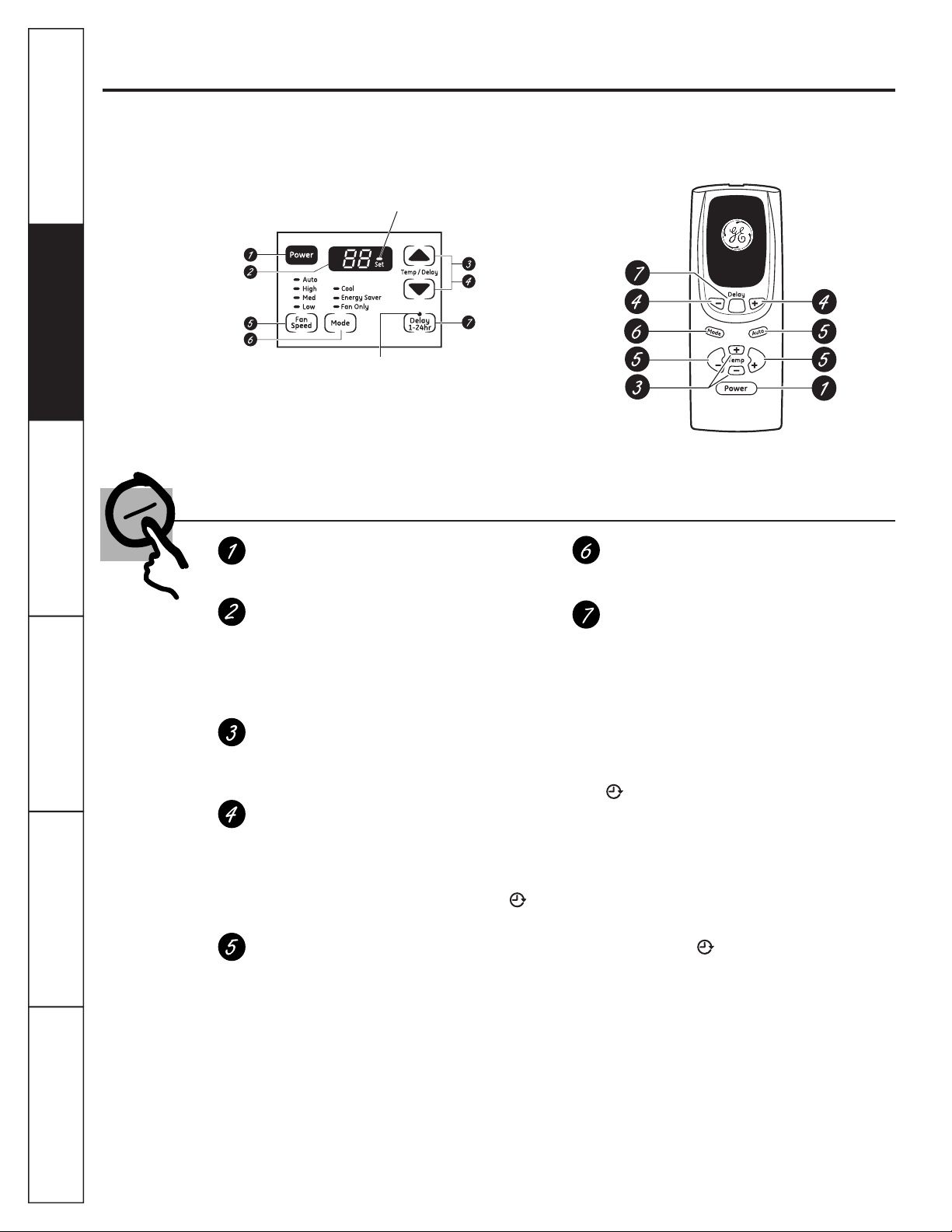
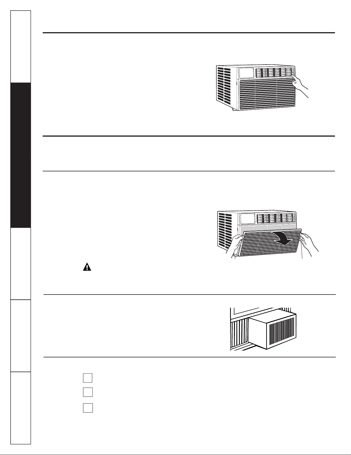
About the controls on the air conditioner
Features and appearance will vary.
Lights next to the touch pads on the air conditioner control panel indicate the selected settings.
Light indicates the unit
Safety InstructionsOperating Instructions
is in the temperature or
delay time Set mode.
Delay 1–24hr
Care and Cleaning
Installation InstructionsTroubleshooting TipsConsumer Support
(on some models)
NOTE: The display always shows the room
temperature except when setting the Set
temperature or the Delay timer.
Light indicates the
delay timer is set.
Air Conditioner Controls
Controls
Power Pad
Turns air conditioner on and off. When turned
on, the display will show the room temperature.
Display
Shows the room temperature or time remaining
on the Delay timer. Shows the Set temperature
while setting the temperature in Cool or Energy
Saver modes. The Set light will turn on while
setting.
Temp Increase ▲ /Decrease ▼ Pads
Use to set temperature when in Cool or Energy
Saver mode. The Set light will turn on while
setting.
Delay Timer Increase▲ (+) /Decrease ▼(–)
Pads
Each touch of the Increase ▲ / Decrease ▼
pads on the unit or the Increase + / Decrease –
pads on the remote control will set the delay
time when using the Delay 1–24hr timer ( ).
The Set light will turn on while setting.
Fan Speed Pads
Use to set the fan speed to Low, Med, High
or Auto on the unit. NOTE: On the remote
control, use the fan speed Increase + /
Decrease – pads to set the fan speeds to Low,
Med or High. Use the Auto pad to turn Auto
fan on.
Delay timer
Decrease
Mode select
Fan speed
Decrease
Temperature
set Increase
and Decrease
FanFan
Remote Control
Mode Pad
Use to set the air conditioner to Cool, Energy
Saver or Fan Only mode.
Delay Pads
Delay ON—When the air conditioner is off, it can
be set to automatically come on in 1 to 24 hours
at its previous mode and fan settings.
Delay OFF—When the air conditioner is on,
it can be set to automatically turn off in 1 to
24 hours.
How to set:
Press the Delay 1–24hr pad on the unit or the
pad on the remote control. Each touch of the
Increase ▲ / Decrease▼pads on the unit or
the Increase + / Decrease – pads on
the remote control will set the timer in
1-hour intervals. The Set light will turn on while
setting.
To review the remaining time on the Delay
1–24hr timer, press the Delay 1–24hr pad on
the unit or the
Use the Increase ▲ / Decrease ▼ pads on the
unit or the Increase + / Decrease – pads on the
remote control to set a new time if desired.
To cancel the timer, press the Delay 1–24hr pad
until the light on the Delay 1–24hr pad goes off.
pad on the remote control.
Delay timer
Increase
Auto Fan
on
Fan speed
Increase
Unit power
on/off
4
Page 5
Do Not Operate in Freezing Outdoor Conditions
This cool-only air conditioner was not designed for
freezing outdoor conditions. It must not be used in
freezing outdoor conditions.
Remote Control
n To ensure proper operation, aim the remote
control at the signal receiver on the air
conditioner.
n The remote control signal has a range of
up to 20 feet.
Cool Mode
Use the Cool mode at Low, Med, High or Auto Fan
Speed for cooling. Use the Temperature Increase ▲
/ Decrease ▼ pads to set the desired temperature
between 64°F and 86°F in 1°F increments.
An electronic thermostat is used to maintain the room
temperature. The compressor will cycle on
and off to keep the room at the set level of comfort.
Set the thermostat at a lower number and the indoor
air will become cooler. Set the thermostat at a higher
number and the indoor air will become warmer.
NOTE: If the air conditioner is off and is then turned on
while set to a Cool setting or if turned from a fan
setting to a Cool setting, it may take approximately
3 minutes for the compressor to start and cooling to
begin.
GEAppliances.com
n Make sure nothing is between the air conditioner
and the remote control that could block the
signal.
n Make sure batteries are fresh and installed
correctly as indicated on the remote control.
Cooling Descriptions
For Normal Cooling—Select the Cool mode and
High or Med fan with a middle set temperature.
For Maximum Cooling—Select the Cool mode
and High fan with a lower set temperature.
For Quieter and Nighttime Cooling—Select the
Cool mode and Low fan with a middle set
temperature.
Operating Instructions Safety Instructions
Care and Cleaning
Energy Saver Mode
Controls the fan.
ON—The fan will cycle on and off with the
compressor. This results in wider variations of room
temperature and humidity. Normally used when the
room is unoccupied. NOTE: The fan may continue to
run for a short time after the compressor cycles off.
Fan Only Mode
Use the Fan Only Mode at Low, Med or High fan
speed to provide air circulation and filtering without
cooling. Since fan-only settings do not provide
cooling, a Set temperature cannot be entered. The
room temperature will appear
in the display.
Auto Fan Speed
Set to Auto fan speed for the fan speed to
automatically set to the speed needed to provide
optimum comfort settings with the set temperature.
If the room needs more cooling, the fan speed
will automatically increase. If the room needs less
cooling, the fan speed will automatically decrease.
OFF—The fan runs all the time, while the compressor
cycles on and off.
NOTE: Auto Fan Speed cannot be used when in the
Fan Only Mode.
NOTE: Auto Fan Speed cannot be used when in the
Fan Only Mode.
Consumer SupportTroubleshooting TipsInstallation Instructions
Power Outage Recovery Feature
In the case of a power outage or interruption, the
unit will automatically restart in the settings last
used after the power is restored. If the Delay 1–24hr
feature was set, it will resume countdown. You may
need to set a new time if desired.
5
Page 6
About the controls on the air conditioner
Additional important information.
Air Direction
Use the lever to adjust the air direction left and right
Safety InstructionsOperating Instructions
only.
Care and cleaning of the air conditioner.
Grille and Case
Turn the air conditioner off and remove the plug from
the wall outlet before cleaning.
Air Filter
The air filter behind the front grille should be checked
and cleaned at least every 30 days or
more often if necessary.
To clean, use water and a mild detergent. Do not use
bleach or abrasives.
Care and Cleaning
Installation InstructionsTroubleshooting TipsConsumer Support
6
To remove:
Open the inlet grille by pulling downward on the tabs
at the top upper corners of the inlet grille until the
grille is in a 45º position. Remove the filter.
Clean the filter with warm, soapy water. Rinse and let
the filter dry before replacing it. Do not clean the filter
in a dishwasher.
CAUTION: DO NOT operate the air
conditioner without a filter because dirt and lint will
clog it and reduce performance.
Outdoor Coils
The coils on the outdoor side of the air conditioner
should be checked regularly. If they are clogged with
dirt or soot, they may be professionally cleaned.
How to Insert the Batteries in the Remote Control
Remove the battery cover by sliding it according
1
to the arrow direction.
Insert new batteries, making sure that the (+)
2
and (–) of battery are installed correctly.
Reattach the cover by sliding it back
3
into position.
NOTES:
n Use 2 “AAA” (1.5 volt) alkaline batteries. Do not
use rechargeable batteries.
n Remove the batteries from the remote control if
the system is not going to be used for a long time.
n Do not mix old and new batteries. Do not mix
alkaline, standard (carbon-zinc) or rechargeable
(ni-cad, ni-mh, etc) batteries.
Tab Tab
Page 7

Installation
Air Conditioner
Instructions
Questions? Call 800.GE.CARES (800.432.2737) or Visit our Website at: GEAppliances.com
In Canada, call 1.800.561.3344 or visit www.GEAppliances.ca
BEFORE YOU BEGIN
Read these instructions completely
and carefully.
•
IMPORTANT — Save these instructions
for local inspector’s use.
•
IMPORTANT — Observe all governing
codes and ordinances.
• Note to Installer – Be sure to leave these
instructions with the Consumer.
• Note to Consumer – Keep these instructions for
future reference.
• Skill level – Installation of this appliance
requires basic mechanical skills.
• Completion time –
• We recommend that two people install
this product.
• Proper installation is the responsibility
of the installer.
• Product failure due to improper installation is not
covered under the Warranty.
• You MUST use all supplied parts and use proper
installation procedures as described in these
instructions when installing this air conditioner.
Approximately 1 hour
CAUTION:
Do not, under any circumstances, cut or remove
the third (ground) prong from the power cord.
Do not change the plug on the power cord
of this air conditioner.
Aluminum house wiring may present special
problems—consult a qualified electrician.
TOOLS YOU WILL NEED
Phillips head screwdriver
Flat-blade screwdriver
ELECTRICAL REQUIREMENTS
Some models require a 115/120-volt AC,
60-Hz grounded outlet protected with a
15-amp time-delay fuse or circuit breaker.
The 3-prong grounding plug minimizes the
possibility of electric shock hazard. If the wall outlet
you plan to use is only a 2-prong outlet, it is your
responsibility to have it replaced with a properly
grounded 3-prong wall outlet.
Some models require 230/208-volt AC,
protected with a time-delay fuse or circuit
breaker. These models should be installed on
their own single branch circuit for best
performance and to prevent overloading
house or apartment wiring circuits, which
could cause a possible fire hazard from
overheating wires.
Ruler or tape measurePencil
Level
Power cord includes a current interrupter device. A
test and reset button is provided on the plug case. The
device should be tested on a periodic basis by first
pressing the TEST button and then the RESET button
while plugged into the outlet. If the TEST button does
not trip or if the RESET button will not stay engaged,
discontinue use of the air conditioner and contact a
qualified service technician.
7
Scissors or knife
Page 8
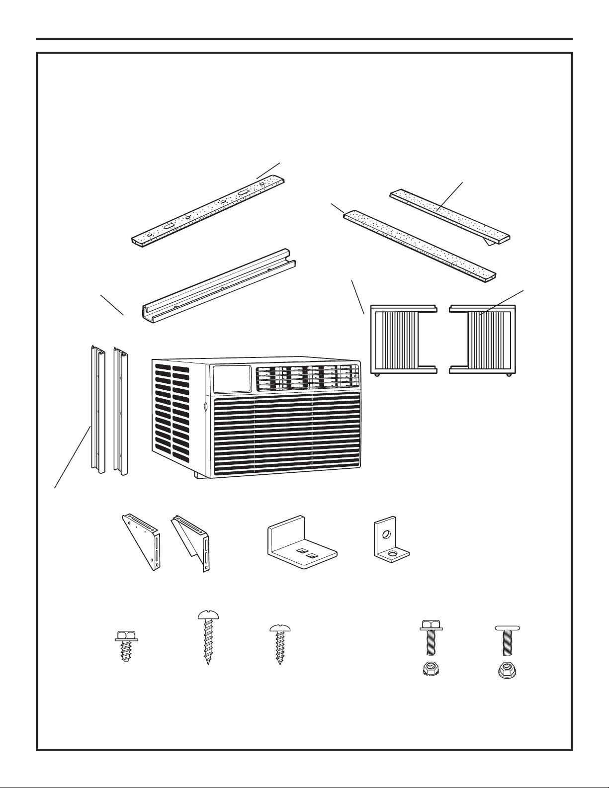
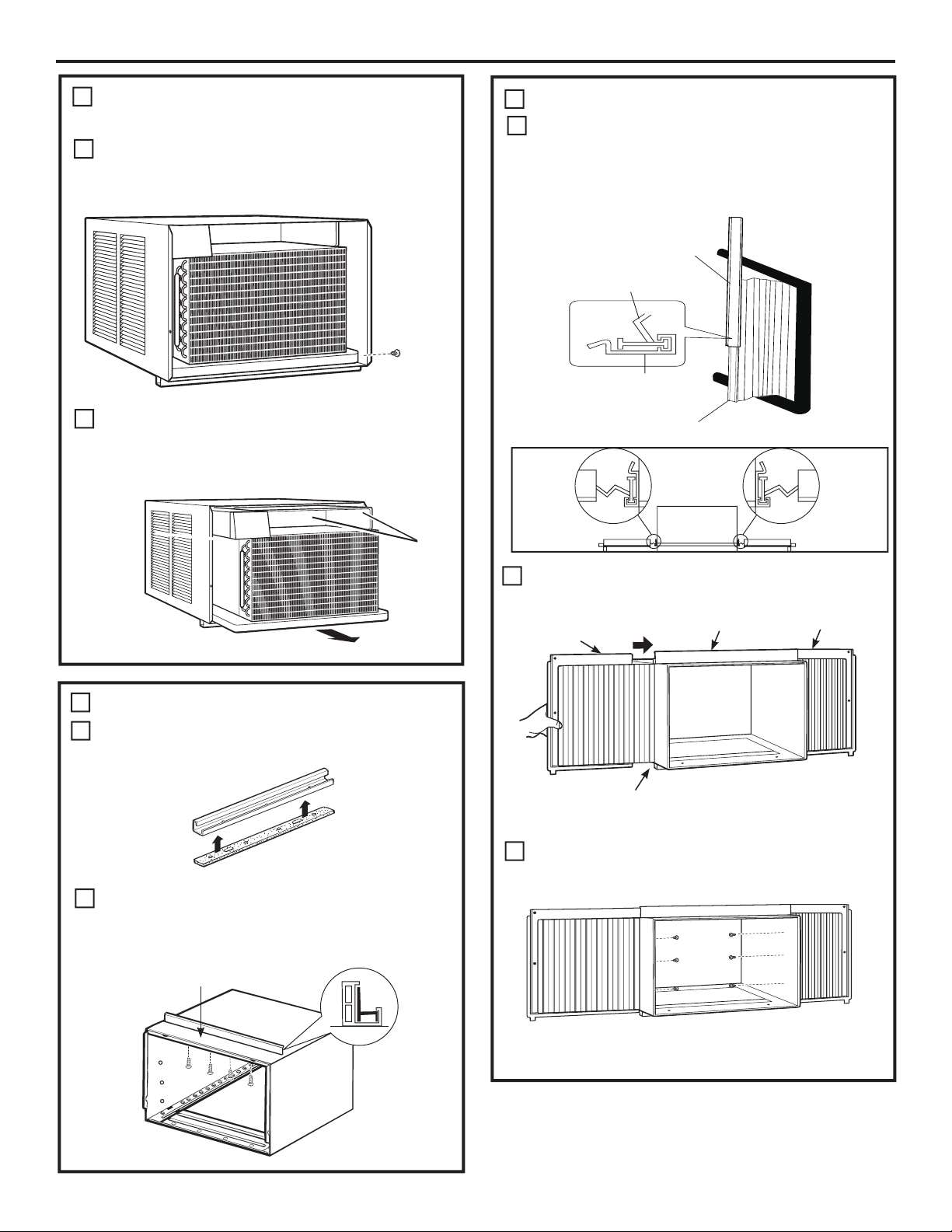
PARTS INCLUDED
(Appearance may vary)
Top
mounting
rail
Installation Instructions
Top rail gasket (1)
Foam top window
gasket (1)
Left
accordion
panel
Window
sash seal
Right
accordion
panel
Side rail (2)
Type A
screws (10)
V-supports (2)
Type B
screws (2)
Sill angle
bracket (2)
Type C
screws (4)
Window
locking bracket
(2)
Type E bolt with
nut (4)
Type F bolt with
nut (2)
8
Page 9
Installation Instructions
WINDOW REQUIREMENTS
1
•These instructions are for a standard double-hung
window. You will need to modify them for other types
of windows.
•All supporting parts must be secured
to firm wood, masonry or metal.
•The electrical outlet must be within reach of the
power cord.
•Follow the dimensions in the table and illustration
for your model.
18 15/32”
26”- 41”
(With accordion panels)
STORM WINDOW REQUIREMENTS
2
A storm window frame will not allow the air
conditioner to tilt toward the outside, and will keep it
from draining properly.
To adjust for this, attach a piece of wood to the sill.
WOOD PIECES
WIDTH: 2”
LENGTH: Long enough to fit inside the window
frame.
THICKNESS: To determine the thickness, place a
piece of wood on the sill to make it 1/2″ higher
than the top of the storm window frame or the vinyl
frame.
Attach securely with nails or screws provided by the
installer.
1/2″ higher
than vinyl frame
(on some windows)
1/2″ higher
than storm
window
frame
Storm window
frame
Sill
Vinyl frame
Wood
3
PREPARE THE AIR CONDITIONER
Pull down the front panel and remove the filter.
A
Remove the front panel by lifting up at an
angle.
Remove the four front screws. Save them
B
for reinstalling the front housing.
Grasp the lower corners of the grille while
C
pressing in on the case sides with your
finger tips. Pull out to release and lift it up.
NOTE: Do not pull the bottom edge
toward you more than 3″ or you may
damage the tabs of the grille.
When the front grille is removed the
D
control panel will still be attached by
a harness. Turn the grille around so
you can see the back side of the grille.
Remove the 2 screws to separate the
control panel housing from the grille.
NOTE: Be sure to save these screws. You will
need them later in the installation.
Remove Screws
9
Page 10
Installation Instructions
3
PREPARE THE AIR CONDITIONER
(continues)
Remove the ground screw from the left
E
side of the case. Keep it in a safe location.
NOTE: Be sure to save this screw. You will need
them later in the installation.
Slide the air conditioner from the case by
F
gripping the base pan handle and pulling
forward while bracing the case. Do not
pull or lift on the styrofoam discharge area.
unit may
FRONT
Do not
pull
or lift
in this
area—
damage
to the
result
PREPARE THE CASE
4
Slide each side retainer onto the edge of
C
each according panel. The figure shows teh
orientation of each accordion panel and side
retainer assembly relative to the case from a
top view of the unit.
SIDE RETAINER
WINDOW FILLER PANEL
SIDE RETAINER
WINDOW FILLER PANEL
Slide the left and right accordion panels
D
into the top and bottom mounting rails.
Top left
Top mounting rail
Top right
PREPARE THE CASE
4
Attach the top rail gasket to the bottom
A
of the top rail.
Install the top mounting rail with 4 type A
B
screws from the inside of the case. Press
firmly to drive the screws into the gasket
and through the top mounting rail.
Top mounting rail
Bottom mounting rail
Attach the side retainers to the case using 6
E
type A screws.
10
Page 11
Installation Instructions
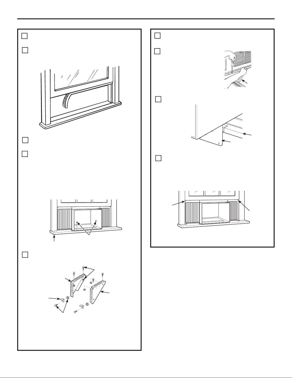
PREPARE THE WINDOW AND INSTALL
5
THE CASE
A
Cut the window sash seal to the proper length.
Peel off the backing and attach the seal to the
underside of the window sash.
Open the window and mark the center of
B
the window sill.
Carefully slide the case into the window
C
and center the case. Lower the window
behind the top mounting rail. Pull the
bottom of the case forward so that the
bottom mounting rail is tight against the
back of the window stool. Mount the case
to the window sill using 2 type B screws.
Drill pilot holes, if necessary.
PREPARE THE WINDOW AND INSTALL
5
THE CASE (continues)
Position the V-supports
E
on the case bottom so
that they will be near
the outside wall. Attach
a V-support to each side
of the bottom of the case
with Type E bolts, 2 for
each support.
Adjust sill angle brackets to rest on sill.
F
Bracket
Extend the left and right accordion panels
G
to the vertical window sashes. Drill pilot
holes and attach the top corners with 2 type
C screws.
V-support
Sill
2 type B screws
Stool
Assemble the V-support and V-support
D
bracket with Type F nut and bolt
Type E bolt
and nut
Left
Sill angle
bracket
V-support Type
F bolt and nut
Right
Type C
screw
Type C
screw
11
Page 12
Installation Instructions
PREPARE THE WINDOW AND INSTALL
5
THE CASE (continues)
H
I
CAUTION:
To prevent broken
glass or damage to
windows, on vinyl or
other similarly
constructed windows,
attach the window
locking bracket to the window side jamb.
Attach the window locking
bracket with one Type C
screw.
This unit contains two
window locking brackets.
Cut the foam top window gasket to the
window width.
Vinyl
Wood
INSTALL THE AIR CONDITIONER
6
IN THE CASE (continues)
Replace the 1 screw removed earlier, one
B
on each side of the case.
IMPORTANT: THE GROUND SCREWS MUST BE
REINSTALLED TO ENSURE PROPER GOUND.
Reinstall the control to the panel housing by
C
replacing the 2 screws you removed earlier.
J
Stuff the foam
between the
glass and the
window to
prevent air and
insects from getting into the room.
NOTE: If the gasket supplied does not fit
your window, obtain appropriate material
locally to provide a proper installation seal.
INSTALL THE AIR CONDITIONER
6
IN THE CASE
Slide the air conditioner into the case by
A
the base pan. Do not push on the controls,
styrofoam air discharge housing or the finned
coils. Make sure the air conditioner is firmly
seated.
Install Screws
Attach the front grille to the case by inserting
D
the tabs on the grille into the slots on the
front top of the case. Push the grille in.
Replace the screws.
E
Base Pan
Do not press on
these areas—
damage to the unit
may result
12
Install the filter and the front grille.
F
Plug in the air conditioner.
F
Page 13
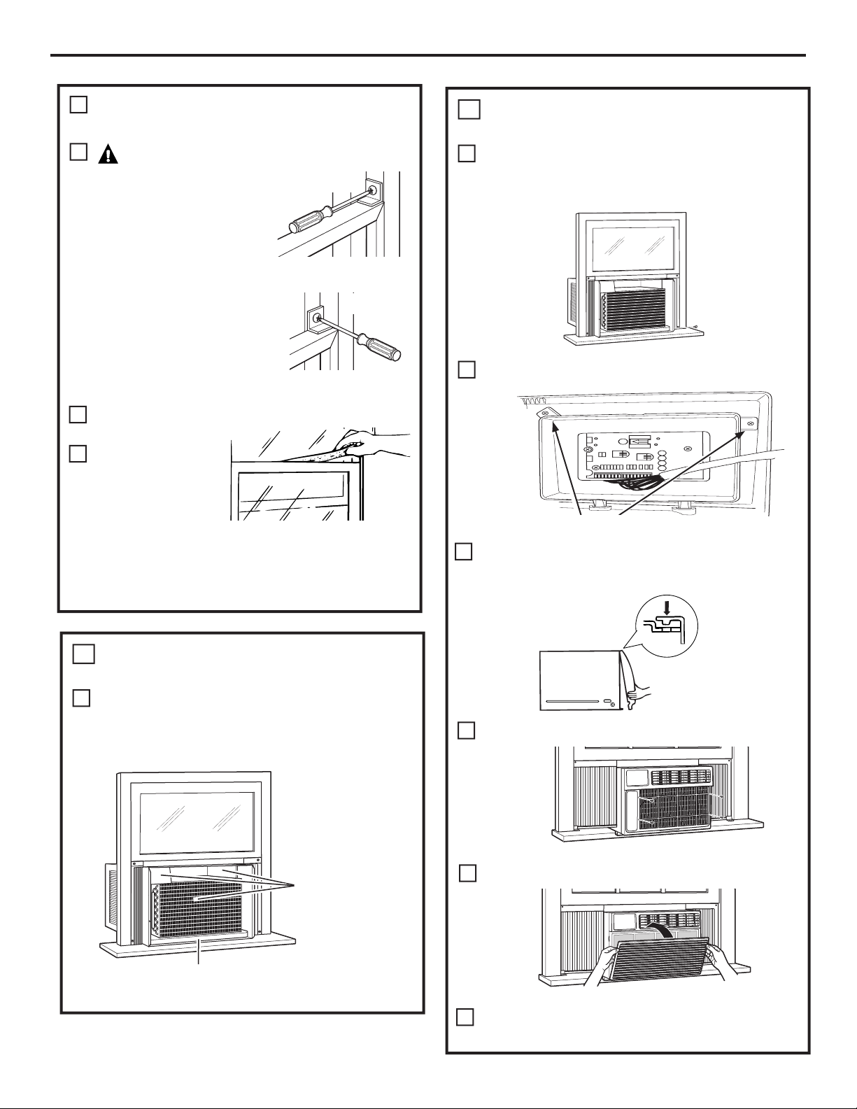
Through-the-Wall Installation Instructions—Optional
The case may be installed through-the-wall
in both existing and new construction.
Read completely, then follow step-by-step.
NOTE: Obtain all materials locally for
mounting the air conditioner throughthe-wall.
IMPORTANT
1
Through-the-wall installation is not
appropriate if any of the side or top louvers
in the case will be obstructed by the wall.
All side and top louvers in the case must
project on the outdoor side of the wall.
The room side of the case must project
into the room far enough to maximize the
balance of the unit.
The case must be installed level from sideto-side and with a slight tilt from front to
rear. Use a level; no more than a 1/2 bubble
will be the correct case slant to the outside.
Lintel angle is required to support bricks or
blocks above opening.
Flashing is required and should extend the
length of the opening to ensure no inside
cavity leakage occurs.
Remove the air conditioner from the case.
A
For specific instruction, refer to the Window
Installation Instructions.
B
Make certain that a wall receptacle is
available close to the hole location or make
arrangements to install a receptacle.
IMPORTANT (cont.)
1
Secure with 14 wood screws anchored at
D
least an inch into the wall support structure.
NOTE: Drill pilot holes, if necessary, for
proper installation. If the frame is oversized,
use shims to prevent case distortion.
FINISH THE WALL OPENING
2
Caulk all four sides on the outdoor side of
A
the case to prevent moisture from getting
through to the interior wall. Use of flashing
(drip rail) will further prevent water from
dripping inside the wall and down the
outside of the building.
Lintel angle
Caulking
OUTSIDE
Air louvers (top
and sides must
project on the
outdoor side of
the wall)
Wood filler and
caulking (above and
below the flashing)
INSIDE
Plaster line
Trim molding (if
desired)
Bottom rail
Place the case in the wall opening and
C
place wood support strips between the case
bottom and the flashing on both sides of the
bottom rail. They should be the same height
as the bottom rail and the same length as
the wall opening.
13
Flashing
(Drip rail)
Flashing
(Drip rail)
Place the air conditioner into the case.
B
Case
bottom
Wood support strips
Bottom
rail
For specific instruction, refer to the Window
Installation Instructions.
Page 14

Troubleshooting Tips.
Problem Possible Causes What To Do
Air conditioner The air conditioner •Make sure the air conditioner plug is pushed
does not start is unplugged. completely into the outlet.
The fuse is blown/circuit • Check the house fuse/circuit breaker box and replace
Safety InstructionsOperating Instructions
breaker is tripped. the fuse or reset the breaker.
Power failure. •The unit will automatically restart in the settings last
used after the power is restored.
•There is a protective time delay (approximately
3 minutes) to prevent tripping of the compressor
overload. For this reason, the unit may not start
normal cooling for 3 minutes after it is turned
back on.
The current interrupter •Press the RESET button located on the power cord plug.
use of the air conditioner and contact a qualified
service technician.
Air conditioner does Airflow is restricted. • Make sure there are no curtains, blinds or furniture
not cool as it should blocking the front of the air conditioner.
The temp control may • In the Cool mode, press the Decrease pad.
The air filter is dirty. • Clean the filter at least every 30 days.
See the Care and Cleaning section.
The room may have been hot. • When the air conditioner is first turned on, you need
to allow time for the room to cool down.
Care and Cleaning
Cold air is escaping. • Check for open furnace registers and cold air returns.
Cooling coils have iced up. •See “Air conditioner freezing up” below.
device is tripped.
not be set correctly.
•If the RESET button will not stay engaged, discontinue
Air conditioner Ice blocks the air flow • Set the controls at High Fan or High Cool and set the
freezing up and stops the air conditioner thermostat to a higher temperature.
The remote control The batteries are inserted • Check the position of the batteries. They should be
is not working incorrectly. inserted in the opposite (+) and (–) direction.
The batteries may be dead. •Replace the batteries.
Installation InstructionsTroubleshooting TipsConsumer Support
Water drips outside Hot, humid weather. • This is normal.
Water drips indoors The air conditioner is not • For proper water disposal, make sure the air conditioner
tilted to the outside. slants slightly from the case front to the rear.
Water collects in Moisture removed from air • This is normal for a short period in areas with little
base pan and drains into base pan. humidity; normal for a longer period in very humid areas.
from cooling the room.
Normal Operating Sounds
n You may hear a pinging noise caused by
water being picked up and thrown against the
condenser on rainy days or when the humidity
is high. This design feature helps remove
moisture and improve efficiency.
n You may hear the thermostat click when the
compressor cycles on and off.
n Water will collect in the base pan during
high humidity or on rainy days. The water
may overflow and drip from the outdoor side
of the unit.
n The fan may run even when the compressor
does not.
14
Page 15

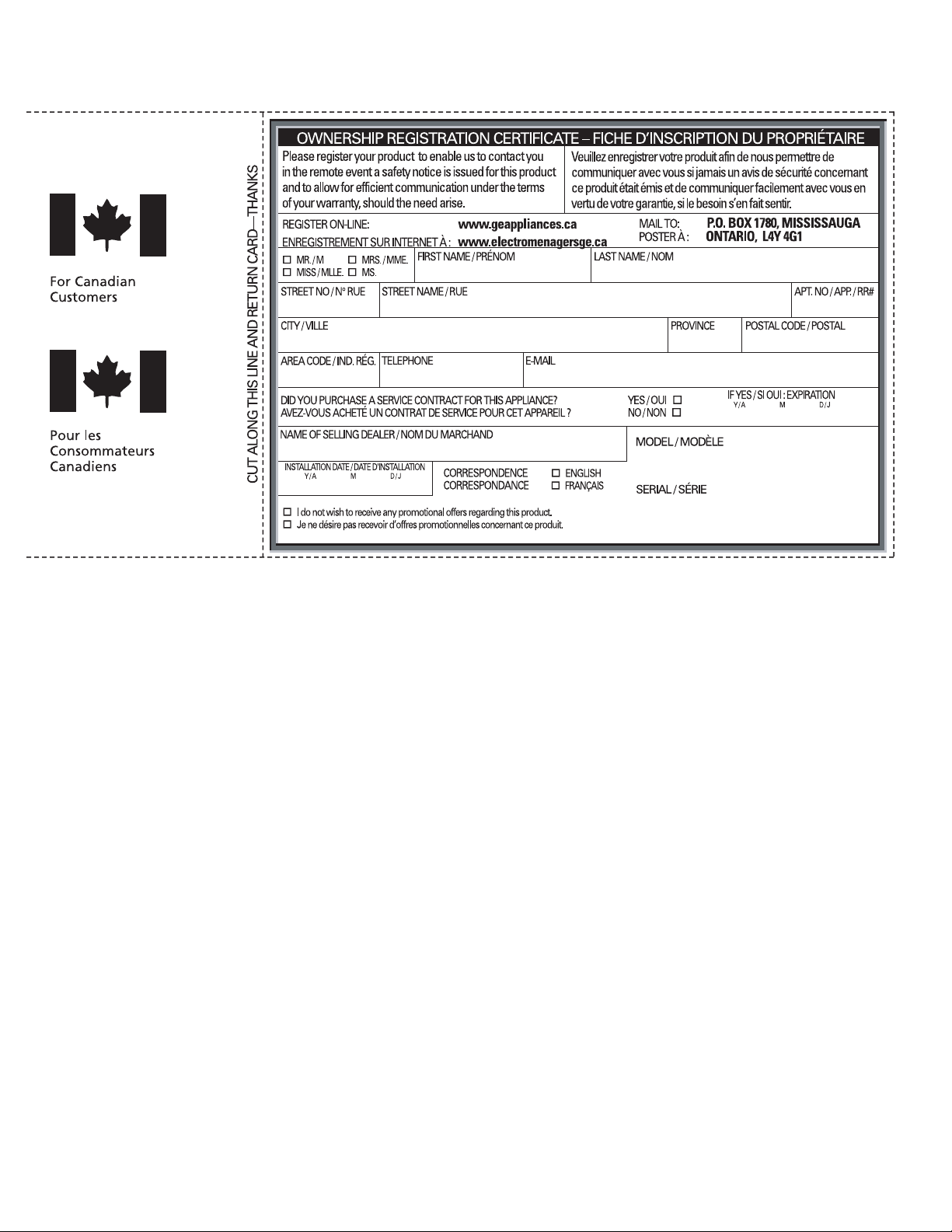
Please place in envelope and mail to:
Veuillez mettre dans une enveloppe et envoyez à :
OWNERSHIP REGISTRATION
P.O. BOX 1780
MISSISSAUGA, ONTARIO
L4Y 4G1
(FOR CANADIAN CONSUMERS ONLY)
15
Page 16
16
Page 17
GE Air Conditioner—One-Year Limited Warranty.
(For customers in the U.S.A.)
All warranty service provided by our Factory Service Centers,
®
or an authorized Customer Care
technician. To schedule service,
visit us on-line at ge.com, or call 800.GE.CARES (800.432.2737).
Have serial number and model number available when calling
Staple your receipt here.
Proof of the original purchase
date is needed to obtain service
under the warranty.
for service.
For The Period Of: GE Will Replace:
One Year Any part of the air conditioner which fails due to a defect in materials or workmanship.
From the date of the During this limited one-year warranty, GE will also provide, free of charge, all labor and related
original purchase service to replace the defective part.
What Is Not Covered:
n Service trips to your home to teach you how to
use the product.
n Improper installation, delivery or maintenance. If you
have an installation problem, or if the air conditioner
is of improper cooling capacity for the intended use,
contact your dealer or installer. You are responsible
for providing adequate electrical connecting facilities.
n Failure of the product resulting from modifications to
the product or due to unreasonable use including failure
to provide reasonable and necessary maintenance.
n In commercial locations, labor necessary to move the
unit to a location where it is accessible for service
by an individual technician.
n Replacement of house fuses or resetting of circuit
breakers.
n Failure due to corrosion on models not corrosion-
protected.
n Damage to the product caused by improper power
supply voltage, accident, fire, floods or acts of God.
n Incidental or consequential damage caused by possible
defects with this air conditioner.
n Damage caused after delivery.
Operating Instructions Safety Instructions
Care and Cleaning
EXCLUSION OF IMPLIED WARRANTIES—Your sole and exclusive remedy is product repair as provided in
this Limited Warranty. Any implied warranties, including the implied warranties of merchantability or
fitness for a particular purpose, are limited to one year or the shortest period allowed by law.
This warranty is extended to the original purchaser and any succeeding owner for products purchased for
home use within the USA. If the product is located in an area where service by a GE Authorized Servicer is
not available, you may be responsible for a trip charge or you may be required to bring the product to an
Authorized GE Service location for service. In Alaska, the warranty excludes the cost of shipping or service calls
to your home.
Some states do not allow the exclusion or limitation of incidental or consequential damages. This warranty
gives you specific legal rights, and you may also have other rights which vary from state to state. To know
what your legal rights are, consult your local or state consumer affairs office or your state’s Attorney General.
Warrantor: General Electric Company. Louisville, KY 40225
Consumer SupportTroubleshooting TipsInstallation Instructions
17
Page 18

GE Air Conditioner—One-Year Limited Warranty.
(For customers in Canada)
All warranty service provided by our Factory Service Centers,
®
or an authorized Customer Care
technician. For service, call
1.800.561.3344. Please have serial number and model number
available when calling for service.
Safety InstructionsOperating Instructions Care and CleaningInstallation InstructionsTroubleshooting TipsConsumer Support
For The Period Of: Mabe Will Replace:
One Year Any part of the air conditioner which fails due to a defect in materials or workmanship.
From the date of the During this limited one-year warranty, Mabe will also provide, free of charge, all labor and
original purchase related service to replace the defective part.
What Is Not Covered:
n Service trips to your home to teach you how to
use the product.
n Improper installation, delivery or maintenance. If you
have an installation problem, or if the air conditioner
is of improper cooling capacity for the intended use,
contact your dealer or installer. You are responsible
for providing adequate electrical connecting facilities.
n Failure of the product resulting from modifications to
the product or due to unreasonable use including failure
to provide reasonable and necessary maintenance.
n In commercial locations, labor necessary to move the
unit to a location where it is accessible for service
by an individual technician.
n Replacement of house fuses or resetting of circuit
breakers.
n Failure due to corrosion on models not corrosion-
protected.
n Damage to the product caused by improper power
supply voltage, accident, fire, floods or acts of God.
n Incidental or consequential damage caused by possible
defects with this air conditioner.
n Damage caused after delivery.
EXCLUSION OF IMPLIED WARRANTIES—Your sole and exclusive remedy is product repair as provided in
this Limited Warranty. Any implied warranties, including the implied warranties of merchantability or
fitness for a particular purpose, are limited to one year or the shortest period allowed by law.
This warranty is extended to the original purchaser and any succeeding owner for products purchased in Canada
for home use within Canada. In-home warranty service will be provided in areas where it is available and deemed
reasonable by Mabe to provide.
Some provinces do not allow the exclusion or limitation of incidental or consequential damages, so the above
exclusion may not apply to you. This warranty gives you specific legal rights, and you may also have other rights
which vary from province to province. To know what your legal rights are in your province, consult your local or
provincial consumer affairs office.
Warrantor: Mabe Canada Inc.,
Burlington, Ontario
18
Page 19

Consignes de sécurité .............20, 21
Consignes d’utilisation
Commandes ..........................22–24
Entretien et nettoyage
Filtre à air ................................24
Serpentins extérieurs .....................24
Instructions de montage ..........25–31
de sécurité
Consignes
Conseils de dépannage ..............32
Bruits normaux de fonctionnement ........32
Assistance à la clientèle
Assistance à la clientèle ...................36
Garantie ..................................35
Enregistrement du titre
de propriété ...........................33, 34
AED14*
AED18*
* Produits homologués EnErgy Star
®
d’utilisation
Consignes
Entretien et
nettoyage
de montage
Instructions
En tant que partenaire d’ENERGY STAR®, GE a
déterminé que ce produit était conforme aux
exigences d’efficacité énergétique d’ENERGY
STAR®.
Inscrivez ici les numéros de modèle et de série :
Numéro de modèle : ____________________
Numéro de Série : _____________________
Vous trouverez ces numéros sur l’étiquette
apposée sur le côté du climatiseur.
Au Canada, visitez-nous au :
www.electromenagersge.ca
dépannage
la clientèle
19
Conseils de
Assistance à
Page 20

IMPORTANTES CONSIGNES DE SÉCURITÉ.
VEUILLEZ LIRE TOUTES LES CONSIGNES AVANT UTILISATION.
AVERTISSEMENT!
Consignes
de sécurité
Pour votre sécurité, les informations contenues dans ce manuel doivent être suivies afin de minimiser
les risques d’incendie, de chocs électriques ou de blessures corporelles.
CONSIGNES DE SÉCURITÉ
Consignes
d’utilisation
nettoyage
Entretien et
n N’utilisez cet appareil qu’aux fins prévues
décrites dans le manuel d’utilisation.
n Ce climatiseur doit être correctement
installé conformément aux Instructions
d’Installation avant toute utilisation.
n Ne débranchez jamais votre climatiseur en
tirant sur le cordon d’alimentation. Prenez
toujours fermement la fiche en main et tirez
pour la sortir de la prise.
n Remplacez immédiatement tout cordon
électrique usé ou endommagé. Un
cordon d’alimentation endommagé doit
être remplacé par un nouveau cordon
d’alimentation obtenu du fabricant. Ne
réparez pas le cordon endommagé. N’utilisez
pas un cordon fissuré ou présentant des
dommages dus aux frottements soit sur
sa longueur ou aux extrémités du côté
de la fiche ou du raccord.
n Eteignez votre climatiseur et débranchez-le
avant de le nettoyer.
n GE n’offre pas de service d’entretien pour les
climatiseurs. Nous vous recommandons de
ne pas essayer d’effectuer l’entretien
de votre climatiseur vous-même.
n Pour votre sécurité, ne stockez pas et
n’utilisez pas de matériaux combustibles,
d’essence ou d’autres vapeurs et liquides
inflammables dans les parages de cet
appareil ou de tout autre appareil.
n Tous les climatiseurs contiennent des
fluides frigorigènes qui, conformément, à la
législation fédérale doivent être retirés avant
la mise au rebut de l’appareil. Si vous mettez
au rebus un ancien appareil contenant des
fluides frigorigènes, vérifiez la procédure à
suivre auprès de la compagnie responsable
de l’élimination.
n Si la prise de courant est d’un format
différent de la fiche, cette prise doit être
changée par un électricien qualifié.
n Ces systèmes de climatisation R410A
nécessitent que les entrepreneurs et
techniciens adoptent des outils, du matériel
et des normes de sécurité approuvés pour
utilisation avec ce réfrigérant. N’utilisez pas
de matériel certifié pour le réfrigérant R22
uniquement.
Instructions
de montage
Conseils de
dépannage
la clientèle
Assistance à
20
BRANCHEMENTS ÉLECTRIQUES
Ne coupez pas ou n’enlevez pas, sous aucun
prétexte, la troisième broche de mise à la terre
du cordon d’alimentation. Pour des raisons de
sécurité, cet appareil doit être correctement mis
à la terre.
N’utilisez PAS d’adaptateur avec cet appareil.
Le cordon d’alimentation de cet appareil est
équipé d’une fiche à trois broches (pour une
mise à la terre) qui s’adapte à la prise de courant
standard à 3 broches (pour une mise à la terre)
pour minimiser les risques de chocs électriques
par cet appareil.
Le cordon d’alimentation est équipé d’un
dispositif d’interruption du courant. Un bouton
d’essai et de réenclenchement est fourni
sur le boîtier de la prise. Vous devez tester le
mécanisme régulièrement en appuyant d’abord
sur le bouton TEST (essai) puis sur le bouton
RESET (réenclenchement) lorsque l’appareil est
branché. Si le bouton TEST (essai) ne bascule
pas ou si le bouton RESET (réenclenchement)
ne reste pas enclenché, cessez d’utiliser votre
climatiseur et appelez un technicien de service
qualifié.
Faites vérifier la prise murale et le circuit
électrique par un électricien qualifié pour
s’assurer que le système est correctement
mis à la terre.
Dans le cas d’une prise biphasée,
l’installateur a la responsabilité et l’obligation
de la remplacer par une prise triphasée
correctement mise à la terre.
Le climatiseur doit toujours être branché
à sa propre prise électrique d’une tension
nominale correspondant à celle indiquée
sur sa plaque signalétique.
Ceci permet d’obtenir un meilleur rendement
du climatiseur et évite de surcharger les circuits
électriques du domicile qui risque d’occasionner
un incendie en surchauffant.
Consultez les Consignes d’Installations, dans
la section Exigences Electriques pour les
exigences de branchements électriques
particuliers.
Page 21

www.electromenagersge.ca
AVERTISSEMENT!
UTILISATION DE RALLONGES—modèles à 115 Volts uniquement
de sécurité
Consignes
Nous déconseillons fortement l’utilisation d’une
rallonge à cause des risques potentiels dans
certaines conditions.
Cependant, si l’utilisation d’une rallonge est
nécessaire, cette dernière doit obligatoirement
être homologuée UL, de calibre 14, à trois
brins avec mise à la terre pour appareil
électroménager et doit être équipée d’une
fiche et d’une prise femelle avec terre. Les
caractéristiques électriques de la rallonge
doivent être de 15 ampères (minimum) et de 125
volts.
MISE EN GARDE :
N’UTILISEZ PAS de rallonge avec un modèle
à 230/208 Volts.
LISEZ ET SUIVEZ SOIGNEUSEMENT CES CONSIGNES DE SÉCURITÉ.
CONSERVEZ CES INSTRUCTIONS
d’utilisation
Consignes
Entretien et
nettoyage
de montage
Instructions
21
dépannage
Conseils de
Assistance à
la clientèle
Page 22

A propos des commandes du climatiseur
Les fonctions et l’aspect peuvent varier.
Les témoins lumineux à côté des touches à effleurement sur le tableau de commandes du climatiseur indiquent les réglages sélectionnés.
Consignes
de sécurité
Consignes
d’utilisation
nettoyage
Entretien et
Instructions
de montage
Conseils de
dépannage
Le témoin indique que l’appareil est en
mode Programmation de la température
ou du délai.
Le témoin lumineux indique que la
minuterie est programmée.
NOTE:L’écran affiche toujours la
température de la pièce sauf lorsque
vous programmez la température ou la
minuterie.
Commandes du Climatiseur
Commandes
Touche d’alimentation
Met le climatiseur en position de marche
ou d’arrêt. L’écran affiche la température
de la pièce lorsque l’appareil est mis en marche.
Affichage
Affiche la température de la pièce ou le temps
restant avant la mise en marche ou l’arrêt de
l’appareil. Affiche la température de réglage lors
de la programmation de la température pour les
modes Cool (refroidissement) ou Energy Saver
(economie d’energie). Le témoin lumineux Set
(programmé) s’allume lors du réglage.
Touches Temp Increase (Augmentation
température) ▲ / Decrease (Réduction
de la température)▼
programmer la température dans les modes Cool
ou Energy Saver. Le témoin lumineux Set s’allume
lors du réglage.
Touches Delay Timer Increase (Augmentation du
délai)▲ (+) / Decrease (Diminution du délai) ▼(-)
Chaque fois que vous effleurez les touches
Increase ▲ / Decrease▼ sur l’appareil ou
les touches Increase + / Decrease – de la
télécommande, vous programmez la durée
du délai lors de l’utilisation de la minuterie Delay
1-24hr (délai de 1-24h) . Le témoin lumineux Set
s’allume lors du glage.
Touches de vitesse du ventilateur
Sont utilisées pour régler la vitesse du ventilateur
de l’appareil sur Low (faible), Med (moyenne),
High (elevée) ou Auto (automatique). REMARQUE :
Sur la télécommande, utilisez les touches Increase
+ / Decrease – pour régler la vitesse du ventilateur
sur Low, Med, ou High. Utilisez la touche Auto
pour allumer le ventilateur en mode Auto.
Sont utilisées pour
Délai 1–24hr
Réduction du délai
Sélection du mode
Réduction de
la vitesse du
ventilateur
Augmentation
et Réduction de
la température
programmée
Touche Mode
Est utilisée pour programmer le climatiseur sur
les modes Cool , Energy Saver ou Fan Only
(ventilateur uniquement).
Touches de Délai
Delay ON (délai de mise en marche)—Lorsque
le climatiseur est éteint, il peut être programmé
pour démarrer automatiquement dans un délai
de 1 à 24 heures à ses réglages précédents (mode,
vitesse du ventilateur).
Delay OFF (délai d’arrêt)—Lorsque le climatiseur
est en fonctionnement, il peut être programmé
pour s’arrêter automatiquement dans un délai de
1 à 24 heures.
Comment le programmer :
Appuyez sur la touche Delay 1-24hr (Délai de 1
à 24 heures) de l’appareil ou sur la touche de
la télécommande. Chaque fois que vous
effleurez les touches Increase ▲ / Decrease ▼sur
l’appareil ou les touches Increase + / Decrease –
de la télécommande, vous programmez la durée
du délai par intervalle de 1 heure. Le témoin
lumineux Set s’allume lors du réglage.
Pour connaître le temps restant sur la minuterie
Delay 1-24hr, appuyez sur la touche Delay 1-24hr
de l’appareil ou sur la touche de la
télécommande. Utilisez les touches Increase▲
/ Decrease▼ sur l’appareil ou les touches
Increase + / Decrease – de la télécommande pour
programmer un nouveau délai si nécessaire.
Pour annuler la minuterie, appuyez sur la touche
Delay 1-24hr jusqu’à ce que le voyant lumineux
sur la touche Delay 1-24hr s’éteigne.
FanFan
Télécommande
Augmentation
du délai
Marche
automatique du
ventilateur
Augmentation
de la
vitesse du
ventilateur
Mise en marche
de l’appareil ON/
OFF (marche/arrêt)
la clientèle
Assistance à
22
Page 23

www.electromenagersge.ca
de sécurité
Consignes
Ne faites pas fonctionner votre appareil
lorsque les températures extérieures sont
en dessous de 0 °C (32 °F).
Télécommande
n Pour vous assurer d’un fonctionnement correct, pointez
la télécommande vers le récepteur de signal
du climatiseur.
nLe rayon d’action de la télécommande s’étend jusqu’à 6,4
m (20 pieds).
Mode Cool (refroidissement)
Utilisez le mode Cool (refroidissement) avec la vitesse
du ventilateur sur Low (faible), Med (moyenne),
High (elevée) ou Auto (automatique) pour refroidir.
Appuyez sur les touches Temperature Increase
(augmentation de la température) ▲ / Decrease
(diminution de la température)▼ pour programmer la
température souhaitée entre 18 °C et 30 °C (64
et 86 °F) par incréments de 0,5 °C (1 °F).
Un thermostat électronique permet de maintenir la
température de la pièce. Le compresseur se met en
marche et s’arrête à intervalles réguliers pour maintenir
la température de la pièce à un niveau de confort choisi.
Réglez le thermostat à une valeur plus basse et l’air
ambiant se refroidira. Réglez le thermostat à une valeur
plus élevée et l’air ambiant se réchauffera.
Ce climatiseur froid seul n’est pas conçu pour
fonctionner avec des températures extérieures en
dessous de 0 °C (32 °F). Il ne doit pas être utilisé lorsque
les températures extérieures sont en dessous de 0°C
(32°F).
n Assurez-vous qu’aucun obstacle pouvant bloquer
le signal ne se trouve entre le climatiseur et la
télécommande.
n Assurez-vous que les piles sont récentes et correctement
installées dans la télécommande.
REMARQUE : Si le climatiseur éteint est allumé alors qu’il
est programmé sur un réglage Cool ou si vous passez
d’un mode Ventilation à un mode de Refroidissement, il
faudra environ 3 minutes pour que le compresseur se
remette en marche et recommence à refroidir.
Descriptions du Refroidissement
Pour un Refroidissement Normal — Sélectionnez
le mode Cool avec la vitesse du ventilateur sur Med
ou High et un réglage à une température moyenne.
Pour un Refroidissement Maximal — Sélectionnez
le mode Cool avec la vitesse du ventilateur sur High
et un réglage à une température plus basse.
Pour un Refroidissement plus Silencieux ou Durant
la Nuit — Sélectionnez le mode Cool avec la vitesse du
ventilateur sur Low et un réglage à une température
moyenne.
d’Utilisation
Consignes
Entretien et
nettoyage
Mode Energy Saver (economie d’énergie)
Contrôle le ventilateur
ON (activé) —Le ventilateur se met en marche et s’arrête
en même temps que le compresseur. Ceci permet une
plus grande variation de la température et du taux
d’humidité dans la pièce. Est en général utilisé lorsque la
pièce est inoccupée.
Mode Fan Only (ventilateur uniquement)
Utilisez le mode Fan Only avec une vitesse de ventilateur
réglée sur Low, Med ou High pour faire circuler l’air et
le filtrer sans le refroidir. Etant donné que le mode Fan
Only ne permet pas de refroidissement, le réglage de la
température n’affiche pas. La température de la pièce
s’affiche à l’écran.
Auto Fan Speed (vitesse du ventilateur auto)
Réglez la vitesse du ventilateur sur auto pour que
la vitesse du ventilateur se règle automatiquement à la
vitesse nécessaire à l’obtention des réglages apportant
un niveau de confort optimal à la température
programmée.
REMARQUE : Le ventilateur peut continuer à fonctionner
quelques instants après que le compresseur se soit
arrêté.
OFF (désactivé)—Le ventilateur fonctionne en continu,
alors que le compresseur se met en marche et s’arrête à
intervalles réguliers.
REMARQUE : La vitesse de ventilateur auto ne peut être
utilisée lorsque le climatiseur est sur le mode Fan Only.
Si la pièce demande un refroidissement supplémentaire,
la vitesse du ventilateur augmente automatiquement. Si
la pièce demande moins
de refroidissement, la vitesse du ventilateur diminue
automatiquement.
REMARQUE : La vitesse de ventilateur auto ne peut être
utilisée lorsque le climatiseur est sur le mode Fan Only.
de montage
Instructions
dépannage
Conseils de
Assistance à
la clientèle
Fonction de conservation des réglages après une coupure de courant
En cas de panne ou d’interruption de courant, l’appareil
redémarre automatiquement après rétablissement
de l’alimentation électrique et conserve les derniers
réglages utilisés. Si la fonction Delay 1-24hr (Délai de 1
à 24 heures) était utilisée, l’appareil reprend son compte
à rebours. Vous aurez peut-être besoin de programmer
une nouvelle heure.
23
Page 24

A propos des commandes du climatiseur.
Information supplémentaire importante.
Consignes
de sécurité
Entretien et nettoyage du climatiseur.
Consignes
d’utilisation
nettoyage
Entretien et
Direction de l’Air
Utilisez le levier pour régler la direction de l’air vers la
gauche ou vers la droite seulement.
Grille et Boîtier
Eteignez et débranchez le climatiseur avant tout
nettoyage.
Filtre à Air
Le filtre à air derrière la grille frontale doit
être vérifié et nettoyé au bout de 30 jours de
fonctionnement ou plus souvent si nécessaire.
Pour retirer :
Ouvrez la grille d’entrée en tirant vers le bas sur les
languettes des coins supérieurs de la grille d’entrée
jusqu’à ce que la grille soit dans une position à 45
degrés. Retirez le filtre.
Nettoyez le filtre avec de l’eau savonneuse tiède.
Rincez le filtre et laissez-le sécher avant de le remettre
dans le climatiseur. Ne nettoyez pas
votre filtre au lave-vaisselle.
Pour le nettoyer, utilisez de l’eau et un détergent doux.
N’utilisez pas d’eau de Javel ou de nettoyants abrasifs.
Languette
Instructions
de montage
Conseils de
dépannage
la clientèle
Assistance à
24
MISE EN GARDE: NE faites PAS
fonctionner le climatiseur sans le filtre sous peine de
le boucher avec de la poussière et de la charpie et de
réduire son efficacité
Serpentins Extérieurs
Les serpentins situés du côté extérieur du climatiseur
doivent être régulièrement vérifiés. S’ils sont obstrués
par des poussières ou de la suie, il est possible de les
faire nettoyer par des professionnels.
Comment Insérer les Piles dans la Télécommande
1
Retirez le couvercle du logement des piles
en le faisant glisser dans le sens indiqué par
la flèche.
2
Insérez les nouvelles piles en vous assurant
que les pôles (+) et (–) de la pile sont orientés
dans la bonne direction.
3
Remettez le couvercle en le faisant glisser.
REMARQUES :
n Utilisez 2 piles alcalines AAA d’1,5 Volt. N’utilisez
pas de piles rechargeables.
n Retirez les piles de la télécommande si vous
prévoyez de ne pas utiliser votre climatiseur
pendant un certain temps.
n Ne mélangez pas des piles neuves avec des
piles usées. Ne mélangez pas ensemble les piles
alcalines, standard (carbone-zinc) ou rechargeables
(ni-cad, ni-mh, etc).
Page 25

Instructions
Climatiseur
de montage
Questions? Composez le 1.800.561.3344 ou visitez notre site web à : www.electromenagersge.ca
AVANT DE COMMENCER
Lisez ces instructions entièrement et attentivement.
•
IMPORTANT — Conservez ces instructions
pour l’inspecteur électrique local.
•
IMPORTANT — Respectez tous les codes et
règlements en vigueur.
• Remarque pour l’installateur – Assurez–vous de
remettre ces instructions au client.
• Remarque pour le client – Conservez ces
instructions pour toute référence future.
• Niveau de compétence – L’installation de cet
appareil demande des connaissances de base en
mécanique.
• Délai d’exécution –
• Nous recommandons que l’installation de ce
produit soit effectuée par deux personnes.
• L’installateur est responsable de l’installation
correcte de l’appareil.
• La panne de l’appareil due à une mauvaise
installation n’est pas couverte par la garantie.
• Vous DEVEZ utiliser toutes les pièces fournies et
suivre la procédure d’installation du climatiseur
décrite dans cette notice.
Environ 1 heure
MISE EN GARDE:
Ne coupez pas ou n’enlevez pas, sous aucun
prétexte, la troisième broche de mise à la terre du
cordon d’alimentation.
Ne changez pas la fiche du cordon d’alimentation
du climatiseur.
Un câblage en aluminium du domicile peut
occasionner des problèmes particuliers—consultez
un électricien qualifié.
OUTILLAGE NÉCESSAIRES
Tournevis cruciforme Phillips
Tournevis à tête plate
EXIGENCES ÉLECTRIQUES
Certains modèles nécessitent une prise mise à la
terre de 115/120 Volts AC, 60 Hz, protégée par
un fusible à action différée ou par un disjoncteur.
La fiche triphasée avec terre réduit le risque de choc
électrique. Si la prise murale que vous envisagez d’utiliser
est biphasée, vous avez la responsabilité et l’obligation de
la remplacer par une prise triphasée correctement mise à
la terre.
Certains modèles nécessitent une prise mise à la
terre de 230/208 Volts AC, protégée par un
fusible à action différée ou par un disjoncteur.
Ces modèles doivent être installés sur leur
propre circuit dérivé pour éviter de surcharger
les circuits électriques du domicile qui peut
occasionner un risque d’incendie par surchauffe
des câbles.
25
Crayon
Niveau
Le cordon d’alimentation est équipé d’un dispositif
d’interruption du courant. Un bouton d’essai et de
réenclenchement est fourni sur le boîtier de la prise. Vous
devez tester le mécanisme régulièrement en appuyant
d’abord sur le bouton TEST (essai) puis sur le bouton
RESET (réenclenchement) lorsque l’appareil est branché.
Si le bouton TEST (essai) ne bascule pas ou si le bouton
RESET (réenclenchement) ne reste pas enclenché, cessez
d’utiliser votre climatiseur et appelez un technicien de
service qualifié.
Règle ou mètre
Ciseaux ou couteau
Page 26

Instructions de montage
PIÈCES INCLUES
(L’aspect peut varier)
Rail de
montage
supérieur
Joint de rail
supérieur (1)
Joint en mousse
supérieur de fenêtre
(1)
Panneau en
accordéon
gauche
Joint d’étanchéité de la fenêtre à
guillotine (fin, adhésif au dos)
Panneau en
accordéon
droit
Rail latéral
Support en V (2)
Type A vis (10)
Type B vis (2)
Ferrure de rebord
de fenêtre (2)
Type C vis (4)
Ferrure de
verrouillage de
la fenêtre (2)
Boulon de type E
avec 2 écrous (4)
Boulon de type E
avec 2 écrous (2)
26
Page 27

Instructions de montage
INSTRUCTION RELATIVE
1
À LA FENÊTRE
• Ces instructions sont valables pour une fenêtre standard à
guillotine à deux châssis mobiles. Vous devrez modifier les
instructions pour les autres types de fenêtres.
• Toute la ferrure de montage doit être solidement fixée au
bois, à la maçonnerie ou au métal.
• La prise d’alimentation électrique doit se trouver à portée
du cordon d’alimentation.
• Suivez les dimensions indiquées pour votre modèle dans le
tableau et sur le croquis.
18 15/32 po”
26 po - 41 po
(Avec les panneaux
en accordéon)
3
PRÉPARATION DU CLIMATISEUR
A
Tirez sur le panneau avant et retirez le filtre.
Retirez le panneau avant en le soulevant incliné
Retirez les quatre vis avant. Mettez-les de côté
B
pour la remise en place du capot avant.
Attrapez les deux coins inférieurs de la grille
C
tout en appuyant sur les côtés du logement
avec le bout des doigts. Tirez vers vous
pour libérer la grille puis sortez-la en levant.
REMARQUE : Ne tirez pas le bord inférieur
vers vous de plus de 3 po ou vous risquez
d’endommager les languettes de la grille.
INSTRUCTIONS RELATIVE À LA CONTRE-
2
FENÊTRE
Le cadre de la contre-fenêtre empêche le climatiseur
de pencher vers l’extérieur, et donc de se drainer
correctement. Pour régler ce problème, fixez un morceau
de bois au rebord de la fenêtre.
MORCEAU DE BOIS
LARGEUR: 2 po
LONGUEUR: Suffisamment long pour se loger à l’intérieur
du cadre de la fenêtre.
ÉPAISSEUR: Pour déterminer l’épaisseur, placez un
morceau de bois sur le rebord de la fenêtre de façon à ce
que le morceau de bois soit ½ po plus élevé que le dessus
du cadre de la contre-fenêtre ou du cadre en vinyle.
Fixez solidement à l’aide de vis ou de clous fournis par
l’installateur.
½ po plus élevé que
le cadre en vinyle (sur
certaines fenêtres)
½ po plus élevé
que le cadre de la
contre-fenêtre
Cadre de la
contre-fenêtre
Rebord
Cadre en vinyle
Bois
Lorsque la grille frontale est retirée, le panneau
D
de commande est toujours raccordé au
faisceau de fils. Tournez la grille de façon à voir
sa face arrière. Retirez les 2 vis pour séparer le
boîtier du panneau de commande de la grille.
REMARQUE : Veillez à conserver ces vis. Elles
seront nécessaires dans une étape ultérieure
de l’installation.
Retirez vis
27
Page 28

Instructions de montage
PRÉPARATION DU CLIMATISEUR
3
Retirez les vis de chaque côté du logement du
E
climatiseur. Mettez-les dans un endroit sûr.
NOTE : Veillez à conserver ces vis. Elles seront
nécessaires dans une étape ultérieure de
l’installation.
Retirez et mettez de côté la vis de mise
F
à la terre.Sortez le climatiseur de son logement
en le faisant glisser et en attrapant la poignée
du conteneur de fond et en tirant vers vous tout
en maintenant le logement. Ne tirez pas et ne
soulevez pas la zone d’évacuation en mousse de
polystyrène.
Ne tirez pas et ne
soulevez pas cette
d’endommager
(suite)
zone,
vous risquez
votre appareil
PRÉPARATION DU LOGEMENT (suite)
4
Glisser chaque dispositif de retenue latéral sur
C
le bord de chaque panneau en accordéon.
L’illustration indique l’orientation de chaque
panneau en accordéon et chaque dispositif de
retenue latéral par rapport au capot depuis une
vue de dessus de l’appareil.
DISPOSITIF DE RETENUE LATÉRAL
WINDOW FILLER PANEL
PANNEAU DE FENÊTRE
DISPOSITIF DE RETENUE LATÉRAL
Glisser les panneaux en accordéon gauche et
D
SIDE RETAINER
SIDE RETAINER
WINDOW FILLER PANEL
PANNEAU DE FENÊTRE
droit dans les rails de montage supérieur et
inférieur.
Partie supérieure
gauche
4
Partie supérieure droite
AVANT
PRÉPARATION DU LOGEMENT
4
Fixez le joint de rail supérieur au dessous du
A
rail supérieur.
Installez le rail de montage supérieur avec 4 vis
B
de type A de l’intérieur du logement. Appuyez
fermement pour enfoncer les vis dans le joint et
à travers le rail de montage supérieur.
Top mounting rail
Rail de montage inférieur
Fixer les dispositifs de retenue latéraux sur le
E
capot à l’aide de 6 vis de type A.
28
Page 29

Instructions de montage
PREPARE THE WINDOW AND INSTALL
5
THE CASE
Découpez le joint de la fenêtre à guillotine à
A
la longueur adéquate. Décollez la pellicule
protectrice et collez le joint sur le dessous du cadre
de la fenêtre.
PRÉPARER LA FENÊTRE ET POSER LE
5
CAPOT (suite)
Monter le support en V et la ferrure du support en
D
V à l’aide d’un écrou et d’un boulon de Type F
Boulon et écrou de
Type E
Gauche
B
Ouvrez la fenêtre et marquez l’axe central
du rebord de la fenêtre.
Faites délicatement glisser le logement dans
C
la fenêtre et centrez-le. Abaissez la fenêtre
derrière le rail de montage supérieur. Tirez le
bas du logement vers l’avant de façon à ce
que le rail de montage inférieur soit plaqué
contre l’arrière du rebord de la fenêtre. Fixez le
logement au rebord de la fenêtre en utilisant
2 vis de type B pour un cadre de bois ou 2 vis
de type C avec les ferrures de verrouillage de
la fenêtre pour les autres types de fenêtres.
Percez des trous de guidage si nécessaire.
Ferrure de
rebord de
fenêtre
Boulon et écrou de Type
F pour support en V
Positionnez les supports en V sur le fond du
E
logement pour qu’ils soient
proches du mur extérieur.
Fixez les supports en V
sur le fond du logement,
de chaque côté, avec des
boulons de type F, 2 pour
chaque support.
Réglez les ferrures de rebord de fenêtre
F
pour qu’elles reposent sur le rebord.
Ferrure
Droit
Support
en V
Rebord
Rebord
2 vis de type B
29
Etirez les panneaux en accordéons gauche
G
et droit jusqu’au cadre vertical de la fenêtre
à guillotine. Percez des trous de guidage et fixez
les coins supérieurs et inférieurs à l’aide de 2 vis de
type C.
Vis de
type C
Vis de
type C
Page 30

Instructions de montage
PRÉPARER LA FENÊTRE ET POSER LE
5
CAPOT (suite)
H
I
MISE EN GARDE:
Pour preventez la verre brisez dans les fenêtres,
sur le vinyle ou d’autres
fenêtres pareillement
construites, attachez une
ferrure de verrouillage
de la fenêtre à la côté
du fenêtre.
Fixez
la ferrure de verrouillage de la fenêtre à l’aide
d’un vis de type C.
Cette unité contient deux
ferrures de verrouillage de
fenêtre.
Découpez le joint d’étanchéité supérieur
en mousse à la largeur de la fenêtre.
Vinyle
Bois
INSTALLATION DU CLIMATISEUR
6
DANS SON LOGEMENT (SUITE)
Remettez en place les deux vis de mise à
B
la terre retirées plus tôt, une de chaque côté du
logement. IMPORTANT : Les vis de mise à la terre
doivent être remises en place pour assurer une
mise à la terre adéquate
Montez de nouveau la commande sur le boîtier du
C
panneau en remettant en place les 2 vis ôtées plus
tôt.
Insérez la mousse entre la vitre et
J
la fenêtre pour
empêcher l’air
et les insectes
de pénétrer dans
la pièce.
NOTE : Si le joint
d’étanchéité fourni
ne s’adapte pas à votre fenêtre, procurez-vous
localement l’article approprié afin d’obtenir
une étanchéité adéquate de l’installation.
INSTALLATION DU CLIMATISEUR
6
DANS SON LOGEMENT
Faites glisser le climatiseur dans le logement par
A
le conteneur du fond. Ne poussez pas sur les
commandes, sur le boîtier en mousse de polystyrène
pour la sortie d’air ni sur les serpentins à ailettes.
Assurez-vous que le climatiseur est correctement
positionné.
Montez vis
Fixez la grille frontale en insérant les languettes
D
de la grille dans les fentes situées dans la partie
supérieure avant du logement. Poussez sur la grille.
E
Replacer les vis.
Conteneur de fond
N’appuyez pas
sur ces zones,
vous pourriez
endommager votre
appareil
30
Poser le filtre et la grille frontale.
F
G
Brancher le climatiseur.
Page 31

Instructions de montage pour une installation à travers un mur—En option
Le logement peut être installé à travers un mur
dans une habitation existante ou neuve.
Veuillez lire entièrement ces instructions, puis les
suivre étape par étape.
REMARQUE : Excepté pour les supports en V
(fournis), veuillez obtenir tous les matériaux
localement pour l’installation du climatiseur à
travers un mur.
IMPORTANT
1
Une installation à travers un mur n’est pas appropriée
si une ou plusieurs des persiennes sur le côté ou sur le
dessus sont obstruées par le mur.
Toutes les persiennes sur le côté ou sur le dessus
doivent dépasser du côté extérieur du mur.
Le côté intérieur du logement doit dépasser
suffisamment dans la pièce pour équilibrer l’appareil.
Le logement doit être installé de niveau de droite à
gauche et légèrement penché de l’avant vers l’arrière.
Utilisez un niveau, environ 1/2 bulle donnera la pente
correcte vers l’extérieur.
Une cornière de linteau est nécessaire pour maintenir
les briques ou les blocs au-dessus
de l’ouverture.
Un solin est nécessaire et doit se prolonger
le long de l’ouverture pour éviter toute fuite
vers l’intérieur du mur.
Retirez le climatiseur de son logement. Pour
A
des instructions particulières, veuillez vous référer aux
Instructions de Montage dans une fenêtre.
Assurez-vous qu’une prise murale se trouve à proximité
B
de l’ouverture ou installez-en une.
IMPORTANT (suite)
1
Fixez le logement à l’aide de 14 vis à bois ancrées d’au
moins un pouce dans la structure du mur.
REMARQUE : Si nécessaire, percez des trous de guidage
pour permettre une installation correcte. Si le cadre est
trop grand, utilisez des cales pour éviter toute distorsion.
FINITION DE L’OUVERTURE DANS LE
2
MUR
Calfeutrez les quatre côtés du côté extérieur du
A
logement pour éviter que l’humidité ne pénètre
par le mur intérieur. L’utilisation
d’un solin (rail d’écoulement) permettra davantage
d’éviter que l’eau ne s’écoule dans le mur et le
long du mur extérieur.
Couche de
plâtre
Cornière de linteau
Calfeutrage
EXTÉRIEUR
Persiennes
(le côté et
le dessus
doivent
dépasser du
côté extérieur
du mur)
Remplissage des
trous et calfeutrage
(au-dessus et en
dessous du solin)
Moulure
(s’il y a lieu)
INTÉRIEUR
Rail inférieur
Positionnez le logement dans l’ouverture dans
C
le mur et placez les bandes de maintien en bois entre
le bas du logement et le solin des deux côtés du rail
inférieur. Elles doivent être de la même hauteur que le
rail inférieur et de la même longueur que l’ouverture
dans le mur.
31
Supports en V
Solin (Rail
d’écoulement)
Solin (Rail
d’écoulement)
B
Placez le climatiseur dans le logement. Pour des
Fond du
logement
Bande de maintien en bois
Rail
inférieur
instructions particulières, veuillez vous référer aux
Instructions de Montage dans une fenêtre.
Page 32

Avant d’appeler le service . . .
Problème Causes possibles Que faire
Le climatiseur ne se Le climatiseur • Assurez-vous que la fiche du climatiseur soit bien branchée
Consignes
Consignes
Entretien et
met pas en marche est débranché. dans la prise murale.
de sécurité
Le fusible a sauté/ • Vérifiez la boîte à fusible/à disjoncteurs et remplacez le fusible
le disjoncteur est ouvert. ou rebranchez le disjoncteur.
Il y a une panne de courant. • S’il se produit une panne de courant, débranchez le climatiseur
en le mettant en position OFF
attendez 3 minutes avant de remettre en marche le climatiseur,
pour éviter de déclencher la surcharge du compresseur.
Le mécanisme d’interruption • Appuyez sur le bouton RESET (remise en marche) situé sur la fiche
de courant est déclanché. du cordon électrique.
• Si le bouton RESET ne reste pas enfoncé, arrêtez le climatiseur
d’air et appelez un technicien qualifié.
d’utilisation
Le climatiseur ne refroidit La circulation d’air est bloquée. • Assurez-vous qu’il n’y a pas de rideau, de store ou de meuble
pas autant qu’il le devrait qui bloque le devant du climatiseur.
Le filtre à air est sale. • Nettoyez le filtre au moins tous les 30 jours. Consulter la section
Entretien et nettoyage.
La chambre était chaude. • Après avoir mis en marche le climatiseur, attendez
que la chambre se refroidisse.
L’air froid s’échappe • Vérifiez les grilles à registre de plancher et les reprises d’air froid.
Les serpentins sont gelés. • Consultez “Le climatiseur gèle” ci-dessous.
nettoyage
Le climatiseur La glace bloque la circulation • Réglez les commandes sur High Fan (vitesse du ventilateur élevée)
gèle d’air et empêche le climatiseur ou High Cool (fort refroidissement) et réglez le thermostat sur une
de refroidir la chambre. température plus élevée.
de la chambre.
(arrêt)
. Quand le courant revient,
De l’eau coule à l’extérieur Il fait très chaud et humide. • C’est normal.
De l’eau coule à l’intérieur Le climatiseur n’est pas • Pour obtenir une bonne évacuation de l’eau, assurez-vous
incliné vers l’extérieur. que le climatiseur soit légèrement incliné de l’avant
du boîtier vers l’arrière.
L’eau s’amasse dans L’humidité est extraite de • C’est normal pendant une période courte dans des régions
le plateau du fond l’air de la chambre et passe peu humides; normal pendant des périodes plus longues
Instructions
Conseils de
dans le plateau du fond. dans des régions très humides.
de montage
dépannage
Bruits normaux de fonctionnement
n
Vous pouvez entendre un cliquetis dû à de l’eau qui
est absorbée et est projetée contre le condensateur les
jours de pluie où quand il y a beaucoup d’humidité. Cette
caractéristique diminue l’humidité et améliore
le rendement.
n
Vous pouvez entendre le claquement du thermostat quand
le compresseur se met en marche et s’arrête.
n
De l’eau s’amasse dans le plateau du bas pendant les
périodes de grande humidité ou s’il pleut. Cette eau peut
déborder et couler de l’appareil du côté extérieur.
n
Le ventilateur peut tourner même quand le compresseur
ne fonctionne pas.
la clientèle
Assistance à
32
Page 33

Please place in envelope and mail to:
Veuillez mettre dans une enveloppe et envoyez à :
OWNERSHIP REGISTRATION
P.O. BOX 1780
MISSISSAUGA, ONTARIO
L4Y 4G1
(FOR CANADIAN CONSUMERS ONLY)
33
Page 34

34
Page 35

Climatiseur GE—Garantie Limitée D’un An. www.electromenagersge.ca
de sécurité
Consignes
Les services sous garantie sont dispensés par nos centres de
réparation ou par nos réparateurs Customer Care
Pour obtenir le service, appelez le 1.800.561.3344. Veuillez
fournir le numéro de série et le numéro de modèle lorsque vous
appelez pour obtenir le service.
®
autorisés.
Pour la période d’ : Nous remplacerons :
Une année Toute pièce de le climatiseur manifestant un vice de matériau ou de fabrication. Durant cette
À compter de la date période de garantie limitée d’une année, Mabe fournira aussi, gratuitement, la main-d’oeuvre
d’achat initial et le service de réparation connexe pour le remplacement de la pièce défectueuse.
Ce qui n’est pas couvert :
n Les déplacements de service à votre maison pour vous
apprendre à utiliser le produit.
n Un montage, une livraison ou un entretien
déficient. Si vous avez un problème de montage
ou si le climatiseur n’a pas la bonne capacité de
refroidissement pour son usage prévu, appelez votre
revendeur ou votre installateur. Vous êtes responsable
de fournir une installation de raccordement électrique
convenable.
n Les pannes occasionnées par des modifications
au produit ou une utilisation non raisonnable, en
particulier une absence d’entretien raisonnable
et nécessaire.
n Dans les emplacements commerciaux, la main-
d’œuvre nécessaire pour déménager l’appareil jusqu’à
un emplacement où il est accessible par un technicien
particulier.
n Le remplacement des fusibles de la maison ou la
réactivation des disjoncteurs.
n Les pannes occasionnées par la corrosion sur les
modèles qui ne sont pas protégés contre la corrosion.
n Les dommages occasionnés par un mauvais voltage de
l’alimentation électrique, un accident, un incendie, une
inondation ou une calamité naturelle.
n Les dommages indirects et consécutifs à la propriété
personnelle occasionnés par des vices possibles de
ce climatiseur.
n Les dommages occasionnés par la livraison.
d’utilisation
Consignes
Entretien et
nettoyage
de montage
Instructions
EXCLUSION DE GARANTIES IMPLICITES – Votre seul et unique recours est la réparation du produit
selon les dispositions de cette Garantie limitée. Toutes les garanties implicites, incluant les
garanties de commercialité et d’adéquation à un usage spécifique, sont limitées à une année ou à
la période la plus courte autorisée par la législation.
Cette garantie est valable pour le premier propriétaire et tout autre propriétaire du produit s’il acheté au Canada
pour utilisation domestique dans Canada. Le service à domicile sous garantie sera fourni là où il est disponible et
dans les régions que Mabe considère que l’offre de service est raisonnable.
Dans certaines provinces, il est interdit d’exclure ou de limiter les dommages directs ou indirects. Il est alors
possible que les limitations ou exclusions ci-dessus ne s’appliquent pas dans votre cas. La présente garantie
vous confère des droits juridiques spécifiques. Vous pouvez bénéficier d’autres droits, qui varient d’une province
à l’autre. Pour connaître les droits dont vous bénéficiez dans votre province, communiquez avec le bureau des
relations avec les consommateurs de votre région.
Garant : Mabe Canada Inc.,
Burlington, Ontario
35
dépannage
Conseils de
Assistance à
la clientèle
Page 36

Assistance à la clientèle.
Site Internet GE
Pour toute question ou pour un besoin d’assistance au sujet de votre appareil ménager, consultez le site
Internet ci-dessus, accessible 24 heures par jour, chaque jour de l’année! À partir du site, vous pouvez
télécharger les manuels d’utilisation.
www.electromenagersge.ca
Studio de conception réaliste www.electromenagersge.ca
Sur demande, GE peut fournir une brochure sur l’aménagement d’une cuisine pour les personnes
à mobilité réduite.
Écrivez: Directeur, Relations avec les consommateurs, Mabe Canada, Inc.
Bureau 310, 1 Factory Lane
Moncton, N.B. E1C 9M3
Pièces et accessoires www.electromenagersge.ca
Ceux qui désirent réparer eux-mêmes leurs électroménagers peuvent recevoir pièces et accessoires
directement à la maison (cartes VISA, MasterCard et Discover acceptées).
Les procédures expliquées dans le présent manuel peuvent être exécutées par n’importe quel utilisateur.
GE n’offre pas de services de réparation pour ce produit. Nous vous recommandons fortement de ne pas tenter de
réparer vous-même le produit.
Vous trouverez dans les pages jaunes de votre annuaire le numéro du Centre de service Mabe le plus proche.
Autrement, appelez-nous au 1.800.561.3344.
Contactez-nous www.electromenagersge.ca
Si vous n’êtes pas satisfait du service après-vente dont vous avez bénéficié :
Premièrement, communiquez avec les gens qui ont réparé votre appareil.
Ensuite, si vous n’êtes toujours pas satisfait envoyez tous les détails—numéro de téléphone compris—au
Directeur, Relations avec les consommateurs, Mabe Canada, Inc.
Bureau 310, 1 Factory Lane
Moncton, N.B. E1C 9M3
36
Page 37

Instrucciones de seguridad ......... 38, 39
Instrucciones de operación
Controle ..................................40–42
Cuidado y limpieza
Bobinas para exteriores ......................42
Filtro de aire ..................................42
Instrucciones de instalación .......43–49
Solucionar problemas ...................50
Sonidos de operación normales ..............50
Servicio al consumidor
Garantía ......................................54
Apoyo al consumidor .........................55
AED14*
AED18*
Producto etiquetado *EnErgy Star
®
OperaciónSeguridad
Cuidado y limpieza
Instalación
Como socio de E
GE ha confirmado que este
producto cumple las directrices
de EnErgy Star® relativas al
rendimiento energético.
Escriba los números de modelo
y serie aquí:
# de Modelo _________________
# de Serie ___________________
Puede encontrar estos números
en una etiqueta en el costado
del acondicionador de aire.
nErgy Star
®
,
problemas
Solucionar
consumidor
Apoyo al
37
Page 38

INFORMACIÓN IMPORTANTE DE SEGURIDAD.
LEA TODAS LAS INSTRUCCIONES ANTES DE USAR.
¡ADVERTENCIA!
SeguridadOperación
Por su seguridad, se debe seguir la información en este manual para minimizar el riesgo de
incendios, descargas eléctricas o lesiones personales.
PRECAUCIONES DE SEGURIDAD
n Use este electrodoméstico solamente para
n Este acondicionador de aire debe instalarse
n Nunca desenchufe su acondicionador de
n Reemplace inmediatamente todos los
Cuidado y limpieza
n Apague la unidad y desenchufe su
n GE no está no apoya que se le proporcione
el propósito determinado según se describe
en el Manual del propietario.
correctamente de acuerdo con las
Instrucciones de instalación antes de su uso.
aire tirando del cable eléctrico. Siempre
agarre firmemente el enchufe y tire de
él directamente hacia afuera.
cables eléctricos que se hayan pelado o que
se hayan dañado de alguna otra manera.
Un cable de corriente dañado no debe
repararse, sino que debe ser sustituido por
uno nuevo que se adquiera del fabricante.
No use un cable eléctrico que muestre
evidencias de deterioro, o daños de
abrasión en su superficie en alguno de sus
extremos.
acondicionador de aire antes de limpiar.
ningún servicio al acondicionador de aire.
Vehementemente recomendamos que
usted no intente proporcionar servicio al
acondicionador de aire usted mismo.
n Por su seguridad…no almacene ni use
materiales combustibles, gasolina u
otros vapores o líquidos inflamables
en la proximidad de éste o algún otro
electrodoméstico.
n Todos los acondicionadores de aire
contiene refrigerantes, los que por Ley
Federal deben ser removidos antes de
desecharlos. Si usted planea deshacerse de
algún producto que contenga refrigerantes,
póngase en contacto con la compañía que
se encarga de recoger su basura para que
le indiquen qué hacer.
n Si el receptáculo no coincide con el enchufe,
un electricista calificado debe reemplazar el
receptáculo.
n Estos sistemas de acondicionadores de
aire R410A requieren que los contratistas
y técnicos usen herramientas, equipos y
estándares de seguridad aprobados para
su uso con este refrigerante. NO use
equipamiento certificado sólo para
refrigerante R22.
Instalación
Solucionar
problemas
Apoyo al
consumidor
38
CÓMO CONECTAR LA ELECTRICIDAD
Bajo ninguna circunstancia, corte o remueva la
tercera púa (tierra) del cable eléctrico. En pos
de la seguridad personal, este electrodoméstico
debe siempre conectarse a tierra.
NO use un enchufe adaptador con este
electrodoméstico.
El cable eléctrico de este electrodoméstico está
equipado con un enchufe de tres púas (tierra)
que combina con un tomacorriente estándar
de tres tomas de pared para minimizar la
posibilidad de una descarga eléctrica.
El cable de alimentación incluye un
dispositivo para interrupción de corriente.
Se incluye un botón de prueba y de reinicio
en el dispositivo. El dispositivo debe ponerse
a prueba periódicamente: primero se presiona
el botón de TEST (prueba) y luego RESET
(reinicio) mientras se encuentra enchufado al
tomacorriente. Si el botón TEST no se dispara
o si el botón RESET no queda enganchado,
deje de utilizar el acondicionador de aire y
comuníquese con un técnico calificado.
Pida a un técnico que inspeccione el
tomacorriente y el circuito para cerciorarse
de que el tomacorriente está conectado a
tierra de la manera apropiada.
Donde exista un tomacorriente de dos
tomas, es su responsabilidad y obligación
personal hacer que dicho tomacorriente
sea reemplazado por uno de tres tomas
con conexión a tierra.
El acondicionador de aire debería siempre estar
conectado a un tomacorriente individual con su
circuito de voltaje correspondiente.
Esto proporciona el mayor rendimiento y
además evita que los circuitos del resto de
la casa se sobrecarguen, lo cual podría causar
incendios por el sobrecalentamiento del
cableado.
Ver las Instrucciones de instalación, en la
sección Requisitos Eléctricos para los requisitos
específicos de conexión.
Page 39

¡ADVERTENCIA!
GEAppliances.com
USO DE CABLES DE EXTENSIÓN—
Debido al potencial de riesgos de seguridad
bajo ciertas condiciones, enérgicamente
recomendamos contra el uso de cables de
extensión.
Sin embargo, si usted se ve en la necesidad
de usar un cable eléctrico de extensión, es
absolutamente necesario que el mismo esté
listado bajo UL, sea calibre 14, del tipo de
3 tomas con conexión a tierra para
electrodomésticos y el índice eléctrico debe
ser de 15 amperios (mínimo) y 125 voltios.
Modelos de 115 voltios solamente
PRECAUCIÓN:
NO USE un cable de extensión con ninguno
de los modelos de 230/208 voltios.
LEA Y SIGA ESTAS INSTRUCCIONES DE SEGURIDAD
CUIDADOSAMENTE.
GUARDE ESTAS INSTRUCCIONES
OperaciónSeguridad
Cuidado y limpieza
Instalación
problemas
Solucionar
consumidor
Apoyo al
39
Page 40

Acerca de los controles en el acondicionador de aire
Las luces al lado de las teclas de toque en el panel de control del acondicionador de aire indicarán los ajustes seleccionados.
Las funciones y el aspecto pueden variar.
SeguridadOperación
1–24 h de retardo
Controles del acondicionador de aire
Controles
Cuidado y limpieza
Instalación
Solucionar
problemas
sincronizador de retardo
Selección de modo
(en algunos modelos)
NOTA: La pantalla muestra
siempre la temperatura
ambiente, excepto al configurar la temperatura
Definida o el Sincronizador de retardo.
Tecla de Power (Encendido)
La luz indica que el
temporizador de retardo
está configurado.
Reducción de velocidad
Aumento y reducción de
Apaga y prende el acondicionador de aire.
Al encenderse, la pantalla mostrará la
temperatura ambiente.
Pantalla
Muestra la temperatura ambiente o
el tiempo restante en el Sincronizador de
retardo. Muestra la temperatura Definida al
configurar la temperatura en los modos Cool
(Frío) o de Energy Saver (Ahorro de energía).
La luz de Ajuste se encenderá durante la
configuración.
Teclas de Temp Aumento ▲/Reducción▼
Usado para ajustar la temperatura cuando
se encuentre en el modo Cool (Frío) o Energy
Saver (Ahorro de energía). La luz de Ajuste se
encenderá durante la configuración.
Teclas de Sincronizador de retardo Aumento
▲(+) / Reducción▼(–)
Cada vez que toque las teclas Aumento ▲/
Reducción ▼ de la unidad o las teclas Aumento
+ / Reducción – en el control remoto definirá
el tiempo de retardo al utilizar el Delay 1–24hr
timer (Sincronizador de retardo 1–24 h) ( ). La
luz de Ajuste se encenderá durante la
configuración.
Teclas de Fan Speed (Velocidad del ventilador)
Usado para ajustar la velocidad del ventilador
a Low (Bajo), Med (Medio), High (Alto) o
Auto (Automática) en la unidad. NOTA: en el
control remoto, utilice las teclas Aumento +
/ Reducción – velocidad de ventilador para
ajustar la velocidad del ventilador en Low (Bajo),
Med (Medio) o High (Alto). Utilice la tecla Auto
para activar el ventilador automático.
Reducción de
del ventilador
ajuste de temperatura
Tecla de MODO
Usado para ajustar el acondicionador de aire
al modo Cool (Frío), Energy Saver (Ahorro de
energía) o Fan Only (Solo ventilador).
Teclas de Delay (Retardo)
Delay ON (ENCENDIDO Retardo)—Cuando
el acondicionador de aire está apagado,
puede ajustarse para que se encienda
automáticamente dentro de 1 a 24 horas en el
modo y configuración de ventilador anterior.
Delay OFF (APAGADO Retardo)—Cuando el
acondicionador de aire está encendido, puede
ajustarse para que se apague automáticamente
dentro de 1 a 24 horas.
Cómo realizar el ajuste:
Pulse la tecla Delay 1–24hr (Retardo 1–24h) en
la unidad o en la tecla del control remoto.
Cada toque de las teclas Aumento ▲ /
Reducción ▼ en la unidad o las teclas Aumento
+ / Reducción – en el control remoto definirá
el temporizador en intervalos de 1 hora.
La luz de Ajuste se encenderá durante la
configuración.
Para revisar el tiempo restante en el
Sincronizador de retardo 1–24 hr, pulse la tecla
de Delay 1–24hr (Retardo 1–24h) en la unidad o
en la tecla del control remoto. Utilice las
teclas Aumento s▲/ Reducción ▼ en la unidad
o las teclas Aumento + / Reducción – en el
control remoto para definir un nuevo
tiempo, si lo desea.
Para cancelar el sincronizador, pulse la tecla
Delay 1–24hr (Retardo 1–24h) hasta que la luz
de dicho control se apague.
FanFan
Control remoto
Aumento de sincronizador
de retardo
Encendido automático del
ventilador
Aumento de velocidad
del ventilador
Encendido/apagado de
la unidad
Apoyo al
consumidor
40
Page 41

GEAppliances.com
No use en las condiciones externas debajo
el punto de congelación
Control remoto
n Para garantizar una operación apropiada, oriente
el control remoto hacia el receptor de señal del
acondicionador de aire.
n El receptor de señal tiene un rango máximo de 20
pies.
Modo Cool (Frío)
Use el modo Cool (Frío) a Low (Bajo), Med (Medio),
High (Alto) o Auto Fan Speed (Velocidad de
ventilador automática) para enfriar. Use las teclas
de Temperature (Temperatura) Aumento ▲ (+)
/ Reducción ▼ (–) para ajustar a la temperatura
deseada entre 64ºF y 86ºF en incrementos de 1ºF.
Se usa un termostato electrónico para mantener
la temperatura ambiente. El compresor hará
ciclo entre apagado y encendido para mantener
la habitación a la temperatura deseada. Ajuste el
termostato a un número menor y el aire interno
se enfriará más. Si lo ajusta a un número mayor,
la temperatura del aire interno se calentará más.
NOTA: si el acondicionador de aire está apagado
y se enciende mientras está configurado en un
Este acondicionador de aire no es diseñado para
usar en temperaturas externas debajo el punto de
congelación. No use en las condiciones externas
debajo el punto de congelación.
n Cerciórese de que no haya nada entre el
acondicionador de aire y el control remoto que
pueda bloquear la señal.
n Cerciórese de que las baterías sean frescas y se
instalen correctamente según se indica en el
control remoto.
ajuste Cool (Frío) o si se cambia de un ajuste de
ventilador a uno de Cool (Frío), puede que pasen
aproximadamente unos 3 minutos hasta que el
compresor arranque y comience el enfriamiento.
Descripciones de enfriamiento
Para enfriamiento normal—Seleccione el modo
Cool (Frío) y ventilador High (Alto) o Med (Medio)
con una temperatura de ajuste media.
Para enfriamiento máximo—Seleccione el modo
Cool (Frío) y ventilador High (Alto) con una
temperatura de ajuste menor.
Para enfriamiento silencioso y enfriamiento
nocturno—Seleccione el modo Cool (Frío) y ventilador
Low (Bajo) con una temperatura de ajuste media.
OperaciónSeguridad
Cuidado y limpieza
Energy Saver Mode (Modo de ahorro de energía)
Controla el ventilador.
ON (ENCENDIDO)—El ventilador hará un ciclo
de encendido y apagado con el compresor. Este
resulta en variaciones mayores en la temperatura
de la habitación y en la humedad. Normalmente
usado cuando la habitación no está ocupada.
NOTA: puede que el ventilador siga funcionando
durante un corto tiempo después de desactivarse el
ciclo del compresor.
OFF (APAGADO)—El ventilador funciona todo el
tiempo, mientras que el compresor pasa por los
ciclos de encendido y apagado.
Modo de Fan Only (Solo ventilador)
Use el modo Fan only (Solo ventilador) a velocidad
Low (Baja), Med (Media) o High (Alta) para
proporcionar circulación de aire y filtración
sin enfriamiento. Debido a que los niveles
de ventilador únicamente no proporcionan
enfriamiento, no se puede introducir una
temperatura Definida. Aparecerá en
pantalla la temperatura ambiente.
NOTA: la Velocidad de ventilador automática no
puede utilizarse en el modo Fan only (Solo ventilador).
Velocidad de ventilador automática
Indique la opción en Velocidad de ventilador
automática para definir automáticamente la
velocidad necesaria para proporcionar una
configuración de comodidad óptima con la
temperatura elegida.
Si la habitación necesita más enfriamiento,
la velocidad del ventilador aumentará
automáticamente. Si la habitación necesita
menos enfriamiento, la velocidad del ventilador
descenderá automáticamente.
NOTA: la Velocidad de ventilador automática
no puede utilizarse en el modo Fan only (Solo
ventilador).
Instalación
problemas
Solucionar
consumidor
Apoyo al
Función de recuperación de pérdida de energía
En caso de la pérdida de la energía o interrupción, la
unidad reiniciará automáticamente en las funciones
de la última vez que fue usado una vez la energía
sea restablecida. Si la función del Delay 1–24hr
(Retardo 1–24h) estaba definido, continuará la cuenta
regresiva. Es posible que usted necesite ajustar un
tiempo nuevo si así lo desea.
41
Page 42

Acerca de los controles en el acondicionador de aire.
Información importante adicionale.
Dirección del aire
SeguridadOperación
Use la palanca para ajustar la dirección del aire hacia
la izquierda y la derecha solamente.
Cuidado y limpieza del acondicionador de aire.
Rejilla y caja
Apague el acondicionador de aire y retire el enchufe
del tomacorriente de la pared antes
de limpiar.
Para limpiar, use agua y un detergente suave.
No use cloro o materiales abrasivos.
Filtro de aire
El filtro de aire detrás de la rejilla frontal debe
inspeccionarse y limpiarse por lo menos cada
30 días o más a menudo si fuese necesario.
Para retirarlo:
Abra la rejilla de entrada empujando hacia abajo
Cuidado y limpieza
las lengüetas en las esquinas superiores de la rejilla
de entrada, hasta que la rejilla se encuentre en una
posición de 45º. Retire el filtro.
Limpie el filtro con agua tibia y jabón. Enjuáguelo y
permita que se seque antes de colocarlo otra vez en
su lugar. No lave el filtro en un lavavajillas.
PRECAUCIÓN: NO OPERE el
acondicionador de aire sin el filtro debido a que la
suciedad y las pelusas lo obstruirán y reducirán su
Instalación
rendimiento.
Lengüetas
Lengüetas
Solucionar
problemas
Apoyo al
consumidor
42
Bobinas para exteriores
Se deben inspeccionar con frecuencia las bobinas
en el lado exterior del acondicionador de aire. Si
las mismas están obstruidas con suciedad u hollín,
podrían limpiarse profesionalmente.
Cómo insertar las pilas en el control remoto
Retire la cubierta de la pila deslizándola
1
de acuerdo con la dirección de la flecha.
Inserte pilas nuevas cerciorándose de que los
2
polos positivos (+) y negativos (–) están
orientados correctamente.
Coloque la cubierta otra vez deslizándola
3
en su lugar.
NOTAS:
n Use 2 pilas alcalinas “AAA” de 1,5 voltios.
No use pilas recargables.
n Retire las pilas del control remoto si no va
a usar el sistema por un período prolongado.
n No mezcle baterías nuevas y viejas. No mezcle
baterías alcalinas, estándar (carbono-cinc)
orecargables (ni-cad,ni-mh,etc.
Page 43

Instrucciones
Acondicionador
de instalación
¿Preguntas? Llame 800.GE.CARES (800.432.2737) o visite nuestra página en la red en: GEAppliances.com
ANTES DE INICIAR
Lea estas instrucciones completa y
cuidadosamente.
•
IMPORTANTE — Guarde estas
instrucciones para uso del inspector local.
•
IMPORTANTE — Observe todos los
códigos y órdenes de ley.
• Nota al instalador – Asegúrese de dejar estas
instrucciones con el consumidor.
• Nota al consumidor – Conserve estas
instrucciones para referencia futura.
• Nivel de destreza – La instalación de este
aparato requiere de destrezas mecánicas
básicas.
• Tiempodeejecución –
• Recomendamos dos personas para
la instalación de este producto.
• La instalación apropiada es la responsabilidad
del instalador.
• La falla del producto debido a una instalación
inadecuada no está cubierta
por la garantía.
• Cuando instale este acondicionador
de aire, DEBE usar todas las piezas
suministradas y usar procedimientos adecuados
de instalación.
Aprox. 1 hora
PRECAUCIÓN:
Bajo ninguna circunstancia corte o remueva la
tercera púa (conexión a tierra) del cable eléctrico.
No cambie el enchufe en el cable eléctrico
de este acondicionador de aire.
Los cables caseros de aluminio podrían presentar
problemas especiales. Consulte
a un técnico electricista calificado.
El enchufe de tres púas con conexión a tierra
minimiza la posibilidad de descargas eléctricas. Si
el tomacorriente de la pared que usted planea usar
solamente tiene 2 tomas, es su responsabilidad hacer
que un técnico lo reemplace por uno de tres tomas
con conexión a tierra.
El cable de alimentación incluye un dispositivo para
interrupción de corriente. Se incluye un botón de prueba
y de reinicio en el dispositivo. El dispositivo debe ponerse
a prueba periódicamente: primero se presiona el botón
de TEST (prueba) y luego RESET (reinicio) mientras se
encuentra enchufado al tomacorriente. Si el botón TEST
no se dispara o si el botón RESET no queda enganchado,
deje de utilizar el acondicionador de aire y comuníquese
con un técnico calificado.
REQUISITOS ELÉCTRICOS
Algunos modelos requieren tomacorrientes de
115/120 voltios de corriente alterna y 60 Hz
conectados a tierra, protegidos con un fusible
de dilatación de tiempo de 15 amperios
o un cortacircuitos.
Algunos modelos requieren 230/208 voltios,
de corriente alterna, protegidos por un fusible
de dilatación de tiempo
o un cortacircuitos. Estos modelos deberían
instalarse en un ramal exclusivo del circuito
para un rendimiento más notable y para
prevenir sobrecargas en los circuitos de
cableados de su casa o apartamento,
lo cual podría representar un riesgo
de incendio por el sobrecalentamiento de los
alambres.
de aire
43
Page 44

Instrucciones de instalación
HERRAMIENTAS QUE NECESITARÁ
Un destornillador de estrella
PARTES INCLUIDAS
(Apariencia puede variar)
Riel de
montaje
superior
Tijeras o cuchilla
Un destornillador
con hoja plana
Nivel
Junta del riel superior (1)
Panel de
acordeón
izquierdo
Lápiz
Una regla o cinta métrica
Sello del marco de la
ventana
(fino, con adhesivo
en la parte posterior)
Empaque superior de
espuma de
la ventana (1)
Panel de
acordeón
derecho
Riel lateral(2)
Soportes en V (2)
Tipo A
tornillos (10)
Tipo B
tornillos (2)
Soporte angular
para alféizar (2)
Tipo C
tornillos (4)
44
Trabas para
marcos (2)
Perno tipo
E con 2
tuercas (4)
Perno tipo
F con 2
tuercas (2)
Page 45

Instrucciones de instalación
REQUISITOS PARA LA VENTANA
1
• Estas instrucciones son para una
ventana estándar de dos pliegues.
Usted necesitará modificar el proceso para otros
tipos de ventanas.
• Todas las partes de apoyo deben quedar totalmente
aseguradas a algún metal, mampostería o a la
madera.
• El tomacorriente eléctrico debe estar al alcance del cable
eléctrico del acondicionador de aire.
• Siga las dimensiones de la tabla y la ilustración según su
modelo.
18 15/32”
26” - 41”
(con paneles de acordeón)
REQUISITOS DE UNA VENTANA
2
DE TORMENTAS
Un marco de ventana de tormentas no permitirá que
el acondicionador de aire se incline hacia el exterior y
evitará que drene apropiadamente. Para solucionar este
problema, adhiera un pedazo de madera a el umbral.
PEDAZOS DE MADERA
ANCHO: 2″
LONGITUD: Lo suficientemente largo como para
ajustar en el interior del marco de la ventana.
GRUESO: Para determinar el grueso, coloque un pedazo
de madera en el umbral para hacerla 1/2″ más alta que
la parte superior del marco de la ventana de tormentas
o del marco vinilo.
Péguelo firmemente con clavos o con tornillos
proporcionados por el instalador.
1/2″ mas alto que el marco
1/2″ más alto
que el marco
de ventana de
tormentas
Marco de
ventana de
tormentas
vinilo (en algunas ventanas)
Umbral
Marco vinilo
Madera
3
PREPARE EL ACONDICIONADOR DE AIRE
Baje el panel frontal y quite el filtro. Quite el panel
A
frontal levantándolo hacia arriba en un ángulo.
Quite los cuatro tornillos frontales. Consérvelos para
B
volver a instalar la carcasa frontal.
Tome las esquinas inferiores de la parrilla mientras
C
presiona hacia adentro sobre los costados de la
carcasa con sus dedos. Tire hacia afuera para
liberar y levántelo.
NOTA: No tire del borde inferior hacia usted más de
3” porque puede dañar las lengüetas de la parrilla.
FRENTE
D
Cuando se retire la parrilla del frente, el panel de
control aún se encontrará adjunto por un arnés. Gire
la parrilla de modo que pueda ver la parte trasera de
la misma. Retire los 2 tornillos para separar el espacio
del panel de control de la parilla NOTA: Asegúrese de
guardar estos tornillos. Los necesitará más adelante
en la instalación.
45
Quite tornillos
Page 46

Instrucciones de instalación
PREPARE EL ACONDICIONADOR DE AIRE
3
Quite los tornillos de cada lado de la carcasa.
E
Consérvelos en una ubicación segura.
NOTA: Asegúrese de guardar estos
tornillos. Los necesitará más adelante en la
instalación.
FRENTE
Quite y conserve el tornillo de cable a tierra.
F
Deslice el acondicionador de aire de la carcasa
tomando la manija de la bandeja inferior y
tirando hacia adelante mientras se sujeta la
carcasa. No tire o levante el área de descarga
de poliestireno
esta zona
provocarse
daños a la
No tire o
levante
porque
pueden
unidad.
4
Deslice cada soporte por el extremo de cada
C
panel correspondiente. La figura muestra la
PREPARE LA CARCASA
4
orientación de cada panel de acordeón y junta de
soporte lateral relativos a la caja desde una vista
superior de la unidad.
Soporte lateral
SIDE RETAINER
Panel para cubrir la ventana
Deslice los paneles de acordeón de izquierda a
D
derecha sobre los rieles de montaje superior e
WINDOW FILLER PANEL
SIDE RETAINER
Soporte lateral
Panel para cubrir la ventana
WINDOW FILLER PANEL
inferior.
Izquierdo superior
Derecho superior
FRENTE
PREPARE LA CARCASA
4
Sujete la junta del riel superior a la parte
A
inferior del riel superior.
B
Instale el riel de montaje superior con 4 tornillos
tipo A desde la parte interior de la carcasa.
Presione firmemente para introducir los tornillos
dentro de la junta y a través del riel de montaje
superior.
Top mounting rail
Riel de montaje inferior
Adjunte los soportes laterales a la caja usando 6
E
tornillos tipo A.
46
Page 47

Instrucciones de instalación
PREPARE THE WINDOW AND INSTALL
5
THE CASE
Corte el sello de la banda de la ventana a
A
la longitud apropiada. Despegue la parte posterior
y pegue el sello a la parte inferior de la banda de la
ventana.
PREPARE LA VENTANA E INSTALE LA
5
CAJA
Enlace el soporte en V y la ficha del soporte en V
D
con una tuerca y un tornillo Tipo F.
Tornillo y tuerca
tipo E
Izquierda
Abra la ventana y marque el centro del alféizar
B
de la ventana.
Con cuidado, deslice la carcasa dentro de la
C
ventana y céntrela. Baje la ventana detrás del
riel de montaje superior. Tire de la parte inferior
de la carcasa hacia adelante para que el riel
de montaje inferior quede firme contra la parte
trasera del alféizar de la ventana. Instale la
carcasa en el alféizar de la ventana utilizando
2 tornillos tipo B para un marco de madera o
dos tornillos tipo C con oporte para bloqueo de
ventana para otros tipos de ventanas. Perfore
orificios piloto, si fuera necesario.
Soporte
angular
del alféizar
Tornillo y tuerca tipo F
para soporte en V
Coloque los soportes en
E
Derecha
V en la base de la carcasa
para que estén cerca de
la pared exterior. Sujete
el soporte en V a cada
lado de la parte inferior
de la carcasa con pernos tipo
F, 2 para cada soporte.
Ajuste los soportes angulares del alféizar de modo
F
Soporte en V
que descansen sobre el alféizar.
Alféizar
Soporte
Alféizar
2 tornillos Tipo B
47
Extienda los paneles en acordeón izquierdo
G
y derecho hacia los marcos verticales de
la ventana. Perfore orificios piloto y sujete
las esquinas superiores e inferiores con
2 tornillos tipo C.
Tornillos
Tipo C
Tornillos
Tipo C
Page 48

Instrucciones de instalación
PREPARE LA VENTANA E INSTALE LA
5
CAJA
H
I
J
PRECAUCIÓN:
En ventanas construidas de vinil o de similar
construcción, conecte el soporte de cierre de la
ventana a el marco de la
ventana para prevenir daño a
la ventana y vidro
quebrado.
Conecte el soporte de cierre
de la ventana con uno tornillo
tipo C.
Esta unidad cuenta con dos fichas
para bloqueo de ventana
Corte la junta de espuma superior de la ventana al
ancho de la ventana.
Rellene la espuma entre
el vidrio y la ventana
para evitar que aire e
insectos
se introduzcan en
la habitación.
NOTA: Si la junta provista no es adecuada para su
ventana, obtenga el material apropiado localmente
para realizar una adecuada instalación de sellado.
Vinilo
Madera
INSTALE EL ACONDICIONADOR EN LA
6
CARCASA
Vuelva a instalar los 2 tornillos quitados antes,
B
uno en cada lado de la carcasa. IMPORTANTE:
Los tornillos de conexión a tierra deberán ser
reinstalados para asegurar una conexión a
tierra adecuada.
Reinstale el control en el espacio del panel
C
reemplazando los 2 tornillos que retiró previamente.
Reinstale tornillos
Sujete la parrilla frontal a la carcasa
D
introduciendo las lengüetas de la parrilla dentro
de las ranuras de la parte superior frontal de la
carcasa. Presione la parrilla hacia adentro.
INSTALE EL ACONDICIONADOR EN LA
6
CARCASA
Deslice el acondicionador de aire dentro de la
A
carcasa de la bandeja inferior. No haga presión
sobre los controles, carcasa de poliestireno de
la descarga de aire o las serpentinas de aletas.
Verifique que el acondicionador de aire se
encuentre firmemente asentado.
No presione
en estas áreas
porque puede
dañarse la
unidad.
Bandeja inferior
Reemplace los tornillos.
E
Instale el filtro y la rejilla frontal.
F
Enchufe el acondicionador de aire.
G
48
Page 49

InstruccionesdeInstalaciónaTravésdelaPared—Opcional
La carcasa puede instalarse a través de la pared en
construcciones existentes y nuevas.
Lea por completo y luego siga todos los pasos.
NOTA:ConexcepcióndelosmontajesdesoportesenV
(incluidos), obtenga todos los materiales en forma local
para montar el acondicionador de aire a través de la
pared.
1
IMPORTANTE
La instalación a través de la pared no es apropiada si
alguna de las persianas laterales o superiores
de la carcasa quedarán obstruidas por la pared.
Todas las persianas laterales y superiores de
la carcasa deben proyectarse sobre la pared exterior
de la pared.
El lado interior de la carcasa debe proyectarse dentro
de la habitación lo suficiente para potenciar al máximo
el equilibrio de la unidad.
La carcasa debe estar instalada de lado a lado y con
una pequeña inclinación del frente hacia la parte
trasera. Utilice un nivel; la inclinación correcta de la
carcasa hacia el exterior no deberá ser de más de 1/2
burbuja.
Se requiere un ángulo de dintel para sostener ladrillos
o bloques sobre la abertura.
Se requiere un revestimiento de aislación que
debe extenderse por la longitud de la abertura para
asegurar que no haya pérdidas en las cavidades
internas.
Quite el acondicionador de aire de la caja.
A
Para instrucciones específicas, consulte las
Instrucciones de instalación en una ventana.
Asegúrese de que haya un tomacorriente cerca de la
B
ubicación del orificio o efectúe arreglos para instalar un
tomacorriente.
1
IMPORTANTE (cont.)
Fije con 14 tornillos para madera sujetos por lo menos
D
una pulgada dentro de la estructura de soporte de
la pared.
NOTA: Perfore orificios piloto, si fuera necesario, para una
instalación adecuada. Si el armazón es más grande, utilice
cuñas para prevenir la deformación de la carcasa.
2
TERMINE LA ABERTURA
DE LA PARED
Utilice calafateo en los cuatro costados del
A
lado exterior de la carcasa para que no
ingrese humedad a la parte interna. El uso de
revestimiento de aislación (riel de goteo) evitará
aún más el ingreso de agua dentro de la pared y
en la parte exterior del edificio.
Línea de
yeso
Ángulo de dintel
Calafateo
EXTERIOR
Persianas de
aire (la parte
superior y
los costados
deben
proyectarse
sobre el lado
externo de
la pared)
Relleno de madera
y calafateo (por
encima y debajo de
revestimiento de
aislación)
Soportes en V
Revestimiento de
aislación (riel de
goteo)
Parte inferior
de la carcasa
Riel
inferior
Moldura
(si se desea)
INTERIOR
Riel inferior
Coloque la carcasa en la abertura de la pared y
C
coloque guías de soporte de madera entre la parte
inferior de la carcasa y el revestimiento de aislación
sobre ambos lados del riel inferior. Deben ser de la
misma altura del riel inferior y de la misma longitud de
la abertura de la pared.
49
Revestimiento de aislación
(riel de goteo)
Guías de soporte de madera
B
Coloque el acondicionador de aire dentro de la
carcasa. Para instrucciones específicas, consulte
las Instrucciones de instalación en una ventana.
Page 50

Solucionar problemas.
Problema Causas posibles Qué hacer
El acondicionador de aire El acondicionador de aire • Cerciórese de que el acondicionador de aire está
no enciende está desconectado. enchufado totalmente en el tomacorriente.
SeguridadOperación
El fusible se disparó / • Inspeccione los fusibles / caja de interruptores de la casa
el cortacircuitos se disparó. y reemplace cualquier fusible o reajuste el interruptor.
Interrupción en el • La unidad se reiniciará automáticamente con la configuración
suministro eléctrico. utilizada por última vez luego de reestablecer la electricidad.
• Existe un retraso de tiempo por protección (de aproximadamente
3 minutos) para evitar la desconexión por sobrecarga del compresor.
Por esta razón, es posible que la unidad no comience a enfriar de
forma normal hasta transcurridos 3 minutos desde que volvió a
encenderse.
El dispositivo de interrupción • Presione el botón RESET ubicado en el cable de alimentación.
de corriente se ha activado.
el acondicionador de aire y comuníquese con un técnico calificado.
El acondicionador de aire El flujo de aire está restringido. • Cerciórese de que no existe ninguna cortina, persiana o
no enfría como debería mueble bloqueando el frente del acondicionador de aire.
El filtro de aire está sucio. • Limpie el filtro cada 30 días por lo menos. Ver la sección
de
La habitación podría haber • Cuando el acondicionador de aire se enciende, usted
estado caliente. necesita darle tiempo para que enfrié la habitación.
El aire frío se está escapando. • Cerciórese de que los registros de la calefacción no están
abiertos y se encuentran retornando el aire frío.
Las bobinas de enfriamiento • Ver “El acondicionador de aire se está congelando” más adelante.
Cuidado y limpieza
El acondicionador de aire El hielo bloquea el flujo • Colo que los controles en High Fan (Ventilador Alto) ó High Cool (Frío
se está congelando de aire hacia el acondicionador Alto) y ajuste el termostato a una temperature más alta.
Hay agua goteando afuera Tiempo húmedo y caliente. • Esto es normal.
Hay agua goteando en el El acondicionador de aire • Para drenar el agua apropiadamente, cercíorese de que
interior de la habitación no está inclinado hacia afuera. el acondicionador de aire está inclinado ligeramente
Instalación
Se acumula agua en La humedad removida del aire • Esto es normal por un corto período en áreas con poca
la bandeja y se drena hasta la bandeja. humedad; normal por un período de tiempo más postergado
se congelaron.
de aire evitando que se enfríe
la habitación.
desde el frente hacia atrás.
en áreas más húmedas.
• Si el botón RESET no se mantiene en su lugar, no utilice más
Cuidado y limpieza
.
Solucionar
problemas
Apoyo al
consumidor
50
Sonidos de operación normales
n Quizás escuche un sonido metálico causado por
el agua tomada y tirada contra el condensador
en los días lluviosos o cuando la humedad
es alta. Esta característica de diseño ayuda a
remover
la humedad y mejora la eficiencia.
n Quizás escuche que el termostato hace clic
cuando el compresor hace ciclo entre encendido
y apagado.
n El agua se acumula en la bandeja durante días
lluviosos o con mucha humedad. El agua podría
derramarse y gotear desde el lado externo de
la unidad.
n El ventilador podría funcionar aun si el compresor
no lo hace.
Page 51

Notas. GEAppliances.com
OperaciónSeguridad
Cuidado y limpieza
Instalación
problemas
Solucionar
consumidor
Apoyo al
51
Page 52

Notas.
SeguridadOperación
Cuidado y limpieza
Instalación
Solucionar
problemas
Apoyo al
consumidor
52
Page 53

Notas. GEAppliances.com
OperaciónSeguridad
Cuidado y limpieza
Instalación
problemas
Solucionar
consumidor
Apoyo al
53
Page 54

Garantía de su acondicionador de aire—garantía limitada de un año.
SeguridadOperación
Todos los servicios de garantía los proporcionan nuestros
Centros de Reparación de Fábrica o nuestros técnicos Customer
®
autorizados. Para concertar una cita de reparación,
Care
en línea, 24 horas al día, visítenos al ge.com, o llame al 800.
GE.CARES (800.432.2737). Cuando llame para solicitar servicio,
por favor tenga a mano el número de serie y el número de
modelo.
Grape aquí su recibo.
Se requiere facilitar prueba
de la fecha de compra original
para obtener un servicio
bajo la garantía.
Por el período de: GE reemplazará:
Un año Cualquier parte del acondicionador de aire que falle debido a defectos en los materiales o en
A partir de la fecha la fabricación. Durante esta garantía limitada de un año, GE también proporcionará, sin costo
de la compra original alguno, toda la mano de obra y el servicio relacionado—para reemplazar partes defectuosas.
Lo que no está cubierto:
nViajesdeservicioasucasaparamostrarlecómo
funciona el equipo.
n Instalación o entrega inapropiada, o mantenimiento
impropio. Si usted tiene un problema durante la
instalación, o si su acondicionador de aire no tiene la
capacidad de enfriamiento que usted necesita, póngase
en contacto con nuestro distribuidor o instalador.
Cuidado y limpieza
Usted es responsable de proporcionar las facilidades
de conexión eléctrica necesarias.
n Fallo del producto resultante de modificaciones al
producto o debido a uso irrazonable incluyendo no
proporcionar mantenimiento razonable y necesario.
n Reemplazodefusiblesdelacasaoreajustedelsistema
de circuitos.
n Fallos debido a la corrosión en modelos que no están
protegidos contra la corrosión.
n Dañoalproductocausadoporvoltajeinapropiadohacia
el equipo, accidentes, incendios, inundaciones o actos
de la naturaleza de fuerza mayor.
n Daños incidentales o consecuenciales causados por
defectos posibles con este acondicionador de aire.
n Daños después de la entrega.
n En locales comerciales, la mano de obra necesaria para
retirar la unidad hacia un lugar para revisión por parte
de un técnico individual.
Instalación
EXCLUSIÓN DE GARANTÍAS IMPLÍCITAS—Su único y exclusivo derecho es la reparación del producto,
tal y como se indica en esta Garantía limitada. Cualquier garantía implícita, incluyendo las garantías
implícitas de comerciabilidad o adecuación para un fin determinado, están limitadas a un año o el
período de tiempo más breve permitido por la ley.
Solucionar
Esta garantía se extiende al comprador original y cualquier comprador posterior de productos comprados para uso
problemas
residencial dentro de Estados Unidos. Si el producto está situado en un área que no dispone de servicio por parte
de un proveedor de servicio autorizado de GE, podría tener que hacerse cargo de los costes de envío o bien
podría solicitársele que lleve el producto a una centro de servicio de GE autorizado para realizar la reparación.
En Alaska, la garantía excluye el costo de envío o las visitas de servicio a su casa.
Algunos estados no permiten la exclusión o las limitaciones de daños incidentales o consecuenciales. Esta garantía
da derechos legales específicos, y usted podría tener otros derechos que variarán de estado a estado. Para saber
cuáles son sus derechos legales, consulte a la oficina de asuntos del consumidor local o la oficina del Attorney General
en su localidad.
Apoyo al
consumidor
Garante: General Electric Company. Louisville, KY 40225
54
Page 55

Apoyo al consumidor.
Página Web de GE Appliances
¿Tiene alguna pregunta sobre su electrodoméstico? ¡Pruebe la página Web de GE Appliances 24 horas al día,
cualquier día del año! Para mayor conveniencia y servicio más rápido, ya puede descargar los Manuales de los
Propietarios, pedir piezas o incluso hacer una cita en línea para que vengan a realizar una reparación.
Real Life Design Studio (Estudio de diseño para la vida real)
GE apoya el concepto de Diseño Universal—productos, servicios y ambientes que pueden usar gente de todas
las edades, tamaños y capacidades. Reconocemos la necesidad de diseñar para una gran gama de habilidades
y dificultades físicas y mentales. Para más detalles cobre las aplicaciones de GE Diseño Universal, incluyendo
ideas de diseño para la cocina para personas con discapacidades, mire nuestra página Web hoy mismo. Para
personas con dificultades auditivas, favor de llamar al 800.TDD.GEAC (800.833.4322).
Piezas y accesorios
Aquellos individuos con la calificación necesaria para reparar sus propios electrodomésticos pueden
pedir que se les manden las piezas o accesorios directamente a sus hogares (aceptamos las tarjetas
VISA, MasterCard y Discover). Haga su pedido en línea hoy, 24 horas cada día o llamar por teléfono
al 800.626.2002 durante horas normales de oficina.
Las instrucciones descritas en este manual cubren los procedimientos a seguir por cualquier usuario.
GE no está no apoya que se le proporcione ningún servicio al acondicionador de aire. Vehementemente
recomendamos que usted no intente proporcionar servicio al acondicionador de aire usted mismo.
GEAppliances.com
GEAppliances.com
GEAppliances.com
Póngase en contacto con nosotros
Si no está satisfecho con el servicio que recibe de GE, póngase en contacto con nosotros en nuestra página
Web indicando todos los detalles así como su número de teléfono o escríbanos a:
General Manager, Customer Relations
GE Appliances, Appliance Park
Louisville, KY 40225
GEAppliances.com
55
Page 56

Consumer Support.
GE Appliances Website
Have a question or need assistance with your appliance? Try the GE Appliances Website 24 hours a day,
any day of the year! For greater convenience and faster service, you can now download Owner’s Manuals,
or even order parts on-line. In Canada: www.GEAppliances.ca
In the U.S.A.: GEAppliances.com
Real Life Design Studio In the U.S.A.: GEAppliances.com
GE supports the Universal Design concept—products, services and environments that can be used by
people of all ages, sizes and capabilities. We recognize the need to design for a wide range of physical
and mental abilities and impairments. For details of GE’s Universal Design applications, including kitchen design
ideas for people with disabilities, check out our Website today. For the hearing impaired, please call 800.TDD.
GEAC (800.833.4322).
In Canada, contact: Manager, Consumer Relations, Mabe Canada Inc.
Suite 310, 1 Factory Lane
Moncton, N.B. E1C 9M3
Parts and Accessories In the U.S.A.: GEAppliances.com
Individuals qualified to service their own appliances can have parts or accessories sent directly to their homes
(VISA, MasterCard and Discover cards are accepted). Order on-line today, 24 hours every day or
by phone at 800.626.2002 during normal business hours.
Instructions contained in this manual cover procedures to be performed by any user. GE does not support any
servicing of the air conditioner. We strongly recommend that you do not attempt to service the air conditioner
yourself.
Customers in Canada should consult the yellow pages for the nearest Mabe service center,
or call 1.800.561.3344.
Contact Us In the U.S.A.: GEAppliances.com
If you are not satisfied with the service you receive from GE, contact us on our Website with all the details
including your phone number, or write to: General Manager, Customer Relations
GE Appliances, Appliance Park
Louisville, KY 40225
In Canada: www.GEAppliances.ca, or write to: Director, Consumer Relations, Mabe Canada Inc.
Suite 310, 1 Factory Lane
Moncton, N.B. E1C 9M3
Printed in China
 Loading...