

Page 1
Contents
Ak Con&Yioner
Adapter Plug
Air Direction
Appliance Registration
(;are and Cleaning
Air Filter
(:ondenser
Grilles & Cabinet
(:onsurner Services
(;ontrol
Electrical Requirements
E;nergy-Saving
Extension
(;rounding
Installation Instructions
(loils
Settings
Tips
[;ords
Models ACM15D
ACM24D
15
8-14
3
5
2
6
6
6
6
4
3
Model and Serial Numbers
Problem Solver
Safety Instructions
User Maintenance Instructions 6
Warranty Back [lover
2
7
2
7
3
3
GEAmwer
Center
80~626.2066
m
GEAppiances
——
Page 2
Help us
If you need service
Consumt
somt
service you receive, here are three
NEXT, if you are still not pleased,
hportant
Safety
help you...
Before using your air
conditioner, read this book
carefully.
It
is intended to help you operate
and maintain your new air
conditioner properly.
Keep it handy for answers to your
questions.
If you don’t understand something
or need more help, write (include
your phone number):
Consumer Affairs
GE Appliances
Appliance Park
Louisville, KY 40225
Write down the model
and serial numbers.
You’ll find them on a label behind
the front grille on the left side wall
of the air discharge duct, visible
through the louvers.
These numbers are also on the
Consumer Product Ownership
Registration Card that came with
your air conditioner. Before sending
in this card, please write these
numbers here:
Instructions
Read dl instructions before
using this appliance.
When using this appliance,
exercise basic safety precautions,
including the following:
●
Use this appliance only for its
intended purpose
this Use and Care Book.
● This air conditioner must be
properly installed in accordance
with the Installation Instructions
before it is used. See
instructions on page 3.
●
Never unplug your
by
pul~
Always grip plug firmly and
straight out from the receptacle.
● Repair or replace immediately
all eleetric service cords that
have become frayed or otherwise
damaged.
shows cracks or abrasion damage
along its length or at either the
plug or connector end.
o
Unplug your air conditioner
before making any repairs.
We strongly recommend that any
servicing be performed by a
qualified
on the power cord.
Do not use a cord that
individud..
as described in
air
Aways
grounding
conditioner
pdl
Note:
To obtain service, see the
Services page in the back of this
book.
We’re proud of our service and
want you to be pleased. If for
reason you are not happy with the
steps to
FIRST, contact the people who
serviced your appliance. Explain
why you are not pleased. In most
cases, this will solve the problem.
write all the details-including
your phone number—to:
FINALLY, if your problem is still
not resolved, write:
foliow
for further help.
Manager, Consumer Relations
GE Appliances
Appliance Park
Louisville, Kentucky 40225
Major Appliance Consumer
Action Panel
20 North
Chicago, Illinois 60606
Wacker
Drive
Model Number
Serial Number
Use these numbers in any
correspondence or service calls
concerning your air conditioner.
If you received a damaged
air conditioner . . .
Immediately contact the dealer
(or builder) that sold it to you.
Save time and money.
Before you request
service . . .
Check the Problem Solver on
page 7. It lists causes of minor
operating problems that you can
correct yourself.
2
●
For your safety..
use combustible materials, gasoline
or other flammable vapors or liquids
in the vicinity of this or any other
appliance.
.do not store or
SAVE THESE
INSTRUC~ONS
— — .————
Page 3
Electrical
Safety—IMPORTANT...pleaSe
Read Carefully.
How
to connect
electricity
Ior Dersonal safetv.
this~ppliance m&t be
properly grounded.
Electrical requirements
115-volt models
volt a.c., 60 hz grounded outlet
protected with a 15 amp time delay
fuse or circuit breaker.
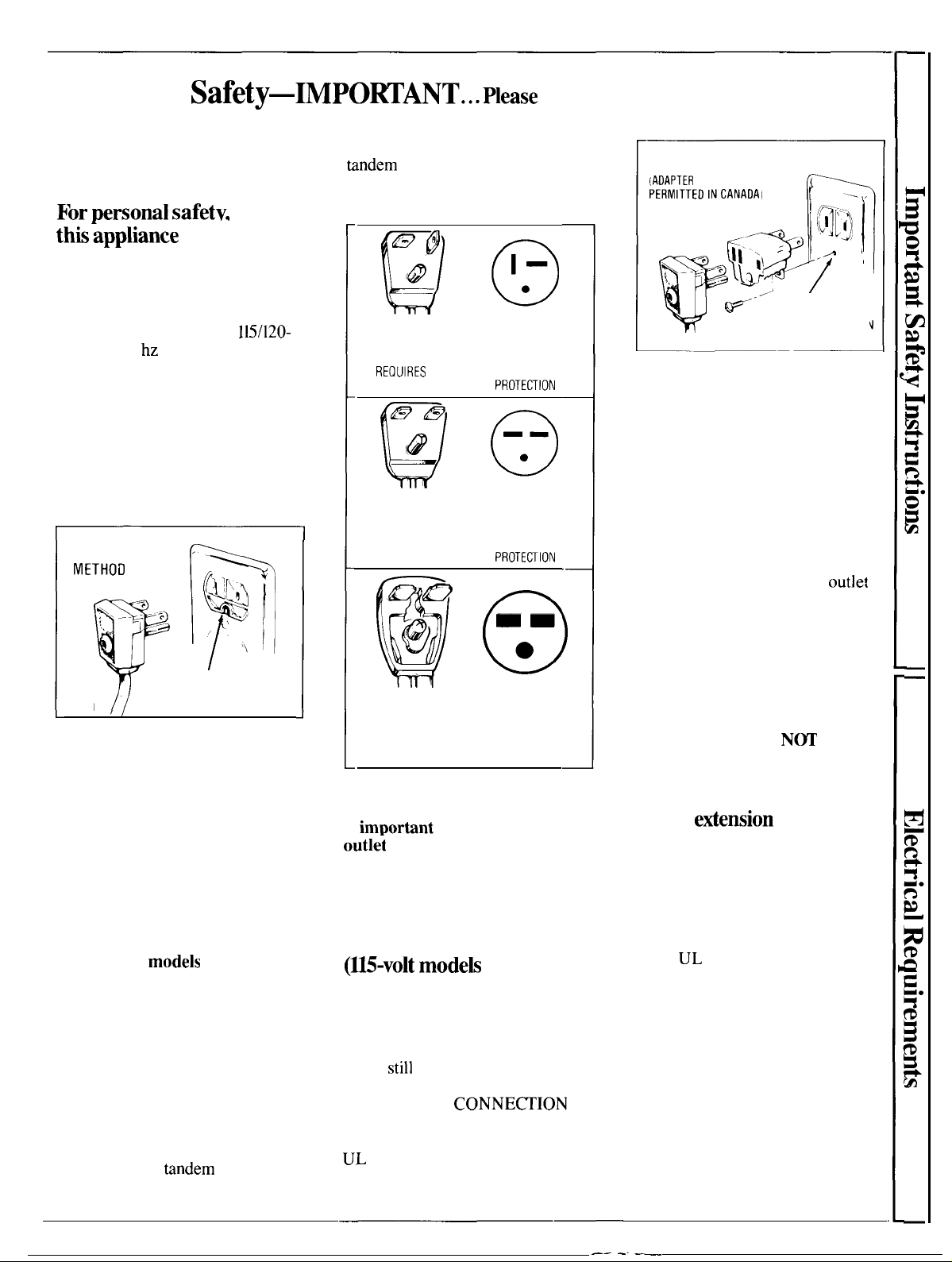
The power cord on these models has
a three-prong (grounding) plug that
mates with a standard three-prong
(grounding) wall outlet (Fig. 1) to
minimize the possibility of electric
shock hazard from these appliances.
PREFERRED
METHOD
\
. -.;”;:
Fig. 1
T
Where a standard two-prong wall
outlet is encountered, it is your
personal responsibility and obligation
to have it replaced with a properly
grounded three-prong wall outlet.
DO NOT, UNDER ANY
CIRCUMSTANCES, CUT
OR REMOVE THE THIRD
(GROUND) PRONG FROM
THE POWER CORD.
230/208-volt
own single branch circuit supplying
230/208-volt a.c., protected with a
time delay fuse or circuit breaker.
This is recommended for best
performance and to prevent
overloading house wiring circuits,
which could cause a possible fire
hazard from overheating wires.
The power cord on these models
has a 230/208-volt perpendicular,
tandem or large
that mates respectively with a
require a
models
tindem
115/120-
~
~>
?
\
&
~+
/.
m
‘\
/
INSURE PROPER
GROUND EXISTS
BEFORE USE
require their
type plug
230/208-volt perpendicular,
tandem or large tandem type wall
outlet. These types of outlets are
available at most hardware stores.
@@
230/208-VOLT
PERPENDICULAR TYPE WALL OUTLET
LINE CORD PLUG
REOUIRES
LINE CORD PLUG
REQUIRES 15 AMP TIME DELAY FUSE
20 AMP TIME DELAY FUSE
OR CIRCUIT BREAKER
@e
230/208-VOLT
TANDEM TYPE
OR CIRCUIT BREAKER
MATCHING
PROTEOION
MATCHING
WALL OUTLET
PROTE~lON
D
,,
@
mm
●
@c
230/208-VOLT
LARGE TANDEM TYPE WALL OUTLET
LINE CORD PLUG
REQUIRES 30 AMP TIME DELAY FUSE
OR CIRCUIT BREAKER PROTECTION
Whether your air conditioner is a
115-volt or a 230/208-volt unit, it
is
im~ortint
outle~
qualified electrician if there is
any doubt as to whether a proper
ground exists.
to have the wall
and circuit checked by a
Use of adapter plug
(U5-volt modeh
Because of potential safety hazards
under certain conditions, we
strongly recommend against use
of an adapter plug.
if you
still
elect to use an adapter,
where local codes permit, a
TEMPORARY
may be made to a properly grounded
two-prong wall outlet by use of a
UL listed adapter (Fig. 2) available
at most local hardware stores.
MATCHING
only)
However,
CONNE~ION
TEMPORARY METHOD
(AOAPTER
PLUGS NOT
PERMITTEOINCANAOA,
ALIGN LARGE
PRONGS/SLOTS ,
>-:
>
v
Fig. 2
The larger slot in the adapter must be
aligned-with the larger slot in the wall
outlet to provide proper polarity in
the connection of the power cord.
CAUTION: Attaching the adapter
ground terminal to wall outlet cover
screw does not ground the appliance
unless cover screw is metal, and not
insulated, and wall outlet is grounded
through house wiring. You should
have the circuit checked by a qualified
electrician to make sure the
is properly grounded.
When disconnecting the power cord
from the adapter,
adapter with one hand. If this is not
done, the adapter ground terminal is
very likely to break with repeated use.
Should the adapter ground
terminal break, DO
appliance until a proper ground
has again been established.
Use of
Because of potential safety
hazards under certain conditions,
we
use of an extension cord.
if you still elect to use an extension
cord, it is absolutely necessary that
it be a
type appliance extension cord and
that the current carrying rating of
the cord in amperes be equal to or
greater than the branch circuit size
shown on the rating nameplate of
the appliance.
etiension
strongly recommend against the
UL listed 3-wire grounding
e
I;i ~
d
e“’”
INSURE PROPER
GROUND ANO
FIRM CONNECTION
BEFORE USE
always hold the
N~
cords
=
~
fi’[]
p
outlet
USE the
However,
~~•
1
3
——
-.
—
Page 4
Opemting
Your Air Conditioner
Controk
OFF
F!’N
❑
MED.
FAN
LO
FAN
SELECTOR
C:hL
.MED
COOL
LO
COOL
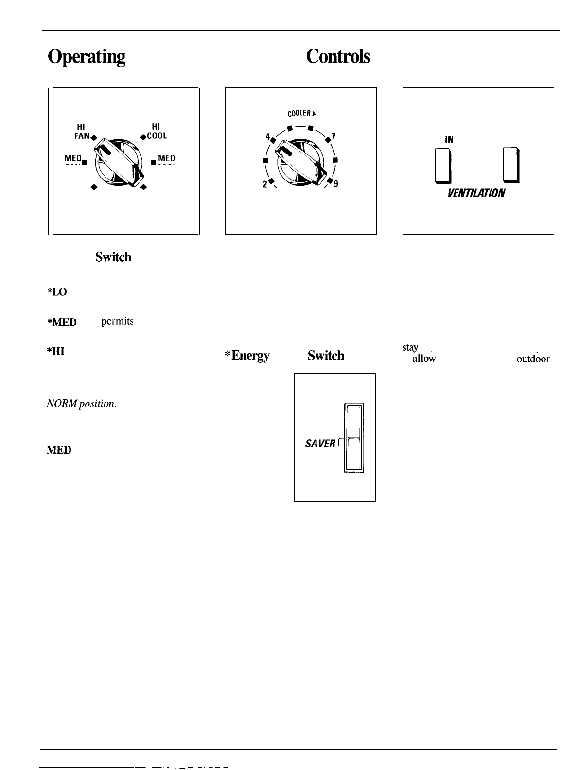
Selector Switih
OFF
turns air conditioner off.
*LO FAN permits low fan speed
operation without cooling.
*MED
FAN
pei-mits
speed operation without cooling.
*HI FAN permits high fan speed
operation without cooling.
*For fan only operation,
Energy Saver Switch must be in
NORMposition.
LO COOL permits cooling with
low fan speed operation.
MED COOL permits cooling with
medium fan speed operation.
HI COOL permits cooling with
high fan speed operation.
medium fan
cOOIERb
56
3
‘lb ● ’
THERMOSTAT
8
10
Thermostat Control
When you turn the Thermostat
Control to the desired setting, it
will automatically control the
temperature of the indoor air. The
higher the number selected, the
cooler the indoor air will be.
*Ene~y
This switch
controls the
fan operation.
NORM
setting allows
continuous
fan function,
circulating
air even
when the
compressor
has cycled off
and the thermostat setting has
been reached. This setting is
recommended for maximum
comfort.
SAVE setting lets the fan cycle on
and off with-the compressor during
cooling. The fan stops when the
thermostat setting is satisfied. This
setting results in longer off time
and wider variations of room
temperature and humidity. This
setting is normally used when the
room is unoccupied.
*For fan only operation, Energy
Saver Switch must be in NORM
position.
Saver Switih
NORM ---
ENERGY
SAVER T
SAVE —
~
1
[
AIR IN
VENTIMTION
AIR OUT
Ventilation Control
When the AIR IN and AIR OUT
buttons are in the out position, the
vent door is closed and only the air
inside the room can be circulated
and conditioned.
Push the AIR IN button and it will
stiy
in, and the vent door will open
to
;11ow
a small amount of outd;or
air to enter the room. Push the AIR
IN button again and it will return
to the out position and the vent
door will close.
Push the AIR OUT button and it
will stay in, and the vent door will
open to allow air, smoke and odors
to be exhausted from the room.
Push the AIR OUT button again
and it will return to the out position
and the vent door will close.
4
——-———-—
Page 5

For normal cooling
1. Set
the
Selector Switch at HI
COOL.
2. Set the Thermostat Control at
the desired number (usually 5-7 is
a good starting position). If room
temperature is not satisfactory
afier a reasonable time, set the
Thermostat Control at a higher
number for a cooler room or at a
lower number for a warmer room.
3. Set the Energy Saver Switch at
NORM position for continuous fan
operation or at SAVE position to
automatically cycle the fan on and
off with the compressor.
4. Be sure the AIR IN and AIR
OUT buttons are in the out position
except for brief periods when you
want to bring outdoor air into the
room or exhaust room air to the
outside.
For
mximum COOQ
1.
Set the Selector Switch at HI
COOL.
2. Turn the Thermostat Control
to 10.
3. Be sure the NR IN and AIR
OUT buttons are in the out
position.
4. Set the Energy Saver Switch at
the NORM position.
For quieter operation
1.
Set the Selector Switch at LO
COOL position.
2. Turn the Thermostat Control to
the desired number.
When the Thermostat Control is set
on 9 or 10 and the Fan is set on low
speed, moisture may freeze on the
coils and prevent the unit from
cooling. If this happens, set the
Fan at high speed and set the
Thermostat Control to a lower
number.
3. Be sure the AIR IN and AIR
OUT buttons are in the out position.
4. Set
the
Energy Saver Switch at
the NORM position.
Note: When the Energy Saver
Switch is at the SAVE position,
changes in the sound level may be
more noticeable than when it’s at
the NORM position.
For
@ttime
During the cooler evening hours, we
r~ommend
Switch at LO COOL for quieter
operation and the Thermostat
Control at mid-range (5 or 6). Be
sure the AIR IN and AIR OUT
buttons are in the out position, and
set the Energy Saver Switch at
NORM or SAVE position.
operation
that you set the Selector
For etireme temperatures
To adjust air direction
Up and down
-
The up-and-down air direction
louvers
pressure on the louvers. They
regulate air discharge upward,
downward or straight out.
Side to side
are controlled by fingertip
ON -
CIRCULAIRE
};
n
I
For fixed side-to-side air
direction,
to ON
is
obhined,
For continuous side-to-side air
circulation, set the Circulaire
Switch to ON
set the Circulaire Switch
until
the desired air
then move it to OFF.
and
leave it there.
directior
For greatest economy and best
performance, we suggest that you
set the Selector Switch at HIGH
COOL in extremely hot weather.
5
Page 6

Care and Cleaning
USER
INSTRUCTIONS
Turn air conditioner off and
remove the plug from the wall
outlet before cleaning.
MNNTEN~CE
Grille & Cabinet
Wipe both sides of grille with a
clean cloth lightly dampened with
mild liquid
or clean with a vacuum cleaner
brush. Be careful not to force the
movable louvers out of position.
Other areas behind the grille may
be wiped or vacuumed, taking care
not to damage the coil fins.
Wash cabinet with mild soap or
detergent and lukewarm water.
Never use strong chemicals,
solvents or bleaching
dishwashing
detergent,
agen~.
Condenser Coils
These coils on the weather side
of the unit should be checked
periodically and cleaned if clogged
with dirt or soot from the atmosphere.
If extremely soiled, they may need
to be steam cleaned, a
through your GE service outlet.
serviee atiable
Air
Hlter
The air filter behind the front grille
should be checked and cleaned at
least every 30 days or as often as it
To remove the filter:
Grasp the tab at the bottom of the
unit and pull downward.
Clean the filter
cleaner to remove light dust. Wash
the filter in lukewarm, soapy water
and rinse in clear water to remove
sticky dust.
When replacing the filter, be sure
the word FRONT is facing you as
you slide the filter back into place.
with a vacuum
Air Inlet
If your air conditioner is mounted
flush inside the room or if the
window sill extends farther into the
room than the chassis, it may be
necessary to remove the air inlet
grille before the filter can be
re
To remove the grille,
inlet grille out by grasping the front
at one side and pushing down to
disengage the tab. Do the same to
the other side.
The air filter can now be removed
from the grille—grasp the tab on
the filter and pull.
After cleaning, replace the air filter
and air inlet grille, pushing the
grille into place.
Grille
Removal
pull the air
—
6
—.—..—.
Page 7

—
Ene~y-saving
● Keep the air filter clean. (See
instructions on page 6.)
c
For most efficient cooling, keep
the Ventilation Control in the
closed position except when you
want to allow a
outdoor air to enter the room or to
exhaust air, smoke or odors from
the room. See page 4.
●
Don’t let the room get too
hot. Whenever possible, turn the
unit on before the room heats up.
When heat is “stored up” in walls,
furniture, rugs and draperies, your
air conditioner takes longer to
produce the desired comfort
condition.
●
Keep windows and doors
closed. Cool, dry air escapes
when they’re open.
. Keep furnace floor registers and
cold air returns closed. Cold air
can easily escape through them.
. Don’t let drapes or furniture block
the front of the unit and restrict air
flow when it is operating.
●
It’s best to operate your air
conditioner at high speed during
extremely hot weather.
small
tips
amount of
Questions?
—
m
-~
Usethis Problem Solver.
———
PROBLEM
AR CONDITIONER
DOES NOT OPERATE
AIR CONDITIONER
“DOES NOT COOL
AS IT SHOULD”
POSSIBLE CAUSE AND REMEDY
●
Not plugged in. Plug may have been bumped
loose by vacuum cleaner or furniture.
●
Ifpluggd
breaker may have tripped.
●
Curtains, blinds or furniture blocking the
front of the air conditioner will restrict airflow.
●
Thermostat Control may not be set high
enough, Turn knob to a higher number. Highest
setting should provide maximum cooling.
When Energy Saver Switch is set at SAVE,
temperature range in room will vary more.
●
Air filter dirty, should be cleaned at least
every 30 days. See instructions on page 6.
●
Room may have been very hot when air
conditioner was first turned on. Allow time
for it to cool down.
●
Cold air maybe escaping through open
furnace
●
AIR IN or AIR OUT button may be in the in
position, allowing hot outside air to enter the
room or cool inside air to leave the room
through the open vent door.
●
Cooling coils have iced up. To melt ice, set the
Selector Switch to HI FAN and the Thermostat
Control to a lower number.
in, fuse could have blown or circuit
floor registers and cold air returns.
● Keep the outdoor condenser coil
clean. (See page
● Turn the air conditioner off
before vacations or extended
absences from home.
6.)
OPERATING SOUNDS
WATER
OUTSIDE
WATER
INSIDE
WATER IN
(ON OUTDOOR SIDE)
If you need more help.. call, toll free:
GE Answer
800.626.2000
consumer information service
DKPPING
DNPPING
BASE
PAN
Center@
● Thermostat click, a metallic sound, maybe
heard when compressor cycles on and off. This
is normal.
●
Fan runs continuously when Selector Switch
is in COOL or FAN position. This is normal.
When Energy Saver Switch is set at SAVE, fan
cycles on and off with compressor.
●
Excess water may overflow in excessively hot
and humid weather. This is normal.
●
Air conditioner must be installed level or tilted
slightly to the outside for proper water disposal.
●
This is normal for a short period in areas with
little humidity; normal for a longer period in
very humid areas. Moisture removed from
indoor air drains to rear of cabinet, where it is
picked up by a fan and thrown against the
outdoor condenser coil.
7
Page 8

BEFORE YOU BEGIN
Read these instructions completely and
arefully.
IMPORTANT—Observe all governing
codes and ordinances.
ELECTRICAL REQUIREMENTS
FOR PERSONAL SAFETY:
s
THIS APPLIANCE MUST BE PROPERLY
GROUNDED. See page 3.
c
DO
N~,
UNDER ANY CIRCUMSTANCES,
CUT OR REMOVE THE THIRD
GROUNDING PRONG FROM THE
POWER CORD.
● WE RECOMMEND THAT YOU DO
NOT USE AN EXTENSION CORD OR AN
ADAPTER PLUG WITH THIS
● DO NOT CHANGE THE PLUG ON THE
POWER CORD OF THIS APPLIANCE.
● FOLLOW NATIONAL ELECTRICAL
CODES OR LOCAL CODES AND
ORDINANCES.
115
v
15 AMP circuit
“parallel” type
230V/208V
20 AMP circuit 15 AMP circuit
“perpendicular” type “tandem” type “tandem” type
APPLNCE.
230V/208V 230V/208V
30 AMP circuit
INSTALLER—Be sure to leave these
instructions with the Consumer.
CONSUMER—Keep these instructions for
future reference.
WINDOW REQUIREMENTS
● Standard double-hung window with actual
opening width of
● Clear vertical opening of
bottom of sash to stool.
● Install the air conditioner
there will be enough clearance around the cabinet
to allow ample circulation of air through
I
191/2”
min.
4
331/4”
331/4”to
to
~’
46!’
191/2”
minimum from
in
a window where
46”
the
unit.
@@@@
● If the electric supply provided does not meet the
above specifications, call a licensed electrician.
● Aluminum house wiring may pose special
problems—consult a qualified electrician.
. This unit requires a separate circuit serving only
this appliance.
I
Note: All supporting parts should be
secured to firm wood, masonry or metal.
~OLS
● Phillips screwdriver
. Blade-type screwdriver
c
NEEDED
Scissors or knife
● Drill
. 1/8” drill bit
. Tape measure
8
Page 9

WINDOW INSTALLATION
❑
REMOVE GRILLE.
1. Remove grille insert.
2. Remove screw securing grille frame to chassis.
EmEPARECHASSIS.
1. Remove chassis shipping screw
of unit. Reinstall screw into base pan to prevent
condensate leakage through screw hole.
\
\
2. Unlock chassis security lock
right side above the control box.
,Y
lo~ted
Ioated
on re
in lower
ar
3. Pull grill from bottom of unit and lift up and off
of
mbinet.
3. Slide chassis from cabinet using base pan
a handle.
(continued next page)
lip~s’
9
Page 10

I
WINDOW
❑
lNSTALL WINDOW FILLER PANELS.
1. Measure center of window opening. Mark
center position
window sash.
2. Raise
3. Position bottom track over sill.
Using track as a template, position center hole of
track over center mark made on window sill.
Mark
Drill three 1/8” diameter holes in window sill.
Attach track to window sill with three 1/2” long
screws provided.
11111
the
window sash.
lomtion of all track holes on window sill.
Flush fit to sill
outdoor side
INSTALLATION(c..ti.ued)
on both the window sill and the
i AL
5.
Fit lower halves of U-shaped sliders into bottom
track. Pivot assembly forward toward sash.
I
1
11
~//
Sash
G
‘Upper
guide
&
INDOOR SIDE
Bottom
track
J
‘i”%
6. Holding upper guide at approximate sash
center, slide left and right-hand sliders into window
sash tracks.
7. Lower window sash behind upper guide.
Center upper guide at sash centerline. Be sure
sash is lowered flush to upper guide.
Drill 1/8” diameter hole in sash to meet center
hole in upper guide.
Install 1/2” long screw through upper guide hole
into sash center hole just drilled. Do not
completely tighten screw yet.
I
4. Fit left and right U-shaped sliders into upper
guide. Be sure drain holes at bottom of sliders are
at the rear (facing out of doors).
Slider mounting holes
on frame behind
window filler panels
I
Drain holes in rear
Upper
gu!de
Top
channel
1
\
Bottom track
8. Drill four 1/8” diameter holes in sash tracks
using sliders as templates. Pull window filler panel
slightly forward if necessary to
Secure sliders in sash tracks with four
diameter screws.
Pull wind
panel
asi
screw ho
lomte screw holes.
11/2”
10
Page 11

❑
iNsTALL CABINET IN
1.
Remove paper backing from seal strip and
affix seal strip to bottom of top channel.
Fasten top channel to top of cabinet with four
long screws.
2. Remove screw fastening upper guide of slider
assembly to window sash. DO
WINDOW.
3. Insert cabinet (with chassis still removed) into
opening of slider assembly and over bottom track.
Permit cabinet top channel to rest against upper
guide of slider assembly.
Push lower corners of cabinet toward outdoors
until cabinet bottom slides
bottom track.
WINDOw.
N~
RAISE
up
and over the bend in
1/2”
5. Cut the foam sash-gap gasket to the correct
window width and “stuff” it between the top of
the lower sash and the glass pane of the upper
sash to provide a seal.
❑
ArlAtN
N~E:
into U-shaped slider assemblies.
1..
Expand both filler panel assemblies toward
sides of
2. Fasten side flanges of filler panel assemblies to
sides of
Be sure to utilize all 3 screw openings in each
flange to prevent air seepage through improperly
sealed flange areas.
wlNDOw FllLERPANELSm CABINET.
Window filler panel assemblies are built
abinet.
mbinet
using 1/2” long screws provided.
Bottom track
fits into cabinet
il
t
track
Insert
screw
II
Sill
“ +
Drill 1/8” hole in sill by drilling down through
center hole in
1/2” screw.
4. Lineup top channel and upper guide center
holes. Replace screw removed earlier from sash.
When cabinet is instilled it will be properly
pitched to outdoors for condensate removal.
~binet.
Fasten
Bottom
track
abinet
1
to sill with
•lNStAUWASSISIN~cABINE1.
1. Slide chassis carefully into
will go.
2.
Lock
security lock to prevent chassis from
being pushed from the outside into the room to
gain illegal entry. Slide security lock screw to the
right. Tighten screw.
neck
‘
-~
abinet
ock
as far as it
11
Page 12

WINDOW INSTALLATION
~co.tinue~,
3. Cabinet is designed with right-side power cord
exit. Power cord is located in cord storage
compartment in lower right corner of chassis.
Cord pulls out and pushes back easily.
If necessary to use left-side power cord exit,
modification must be made. To modify, remove
plastic escutcheon by removing 2 screws and 2
knobs from escutcheon. Redirect power cord to
exit bottom left corner. Replace escutcheon. Use
pliers to snap out plastic offset in bottom left
corner of grille.
4. With main switch in off position, insert power
cord into properly grounded electrical outlet.
See page 3.
❑
SpEciALINslALLATlONs.
To overcome storm window interference, attach
a 2“ wide wood strip to the stool with either nails
or screws.
Strip should be as long as window opening and
flush with back side of stool.
Thickness of wood strip should be determined by
amount of interference.
Air
conditioner
cabinet
Sill
* 2“y
stool
Apron
——— —
Wood
strip
——— — ——
Aluminum
storm
window
frame
Flash
w’
12
— —.
Page 13

t
THROUGH-THE-WALL INSTALLATION
THE
CABINET~YBE
B~HEXISTINGBUILDINGSANDNEWCONSTRUCTION.
INSTALUDTHROUGH THE WALL IN
❑
PREpAREwAILOPENING.
IMPORTANT
. Any side
outdoor side of the wall.
.
The room side of the
louvers
must project on the
mbinet
must project into
the room at least 1“ from the finished wall.
●
The
~binet
must be installed level from side to
side and with a 3/8” tilt from front to rear.
TOOLS REQUIRED
●
Phillips head screwdriver
● Blade-type screwdriver
●
Magnetic stud finder (optional)
●
Tin snips
● Handsaw
●
Level
●
Chisel
●
Concrete saw (if installing through a masonry wall)
● Hammer
●
Caulking gun
● Tape measure
1. Determine size of opening. Measure
w~idth
and height of
abinet
and add 1/8” to each
dimension.
HEIGHT
●
2. Choose the wall opening
lomtion.
+
Be sure
a power receptacle is (or will be) installed nearby.
3. Make the opening. Frame it to support the
weight of the air conditioner. Add metal flashing
over bottom of frame opening and 1“ up on sides to
reduce the possibility of moisture entering the area
between the inner and outer wall.
The flashing lip should be 1“ wide and bent down
45S
See illustration, page 14.
ADDITIONAL MATERIALS NEEDED
c
12 #10 wood screws, 1“ long
c
1 tube high grade caulking compound
●
Wooden framing studs
●
Lintel, if required, to support bricks or blocks
(obtain locally)
above opening.
●
Flashing, aluminum or galvanized steel
EPREPARETHECABINET.
1.
Remove chassis from
Installation,
Page
9.
2. With aulkingcompound orelectriml tape, seal
all holes provided in the
installation hardware not used in this installation.
EIN5TALLCABINET
1.
Place
mbinet
IN
in wall opening.
2. Secure cabinet bottom rail to wooden frame
with two 1“ long #10 wood screws.
abinet.
abinet
WALL.
See
Window
for window
(continued
nextpage)
13
Page 14

I
THROUGH.THE.WALL INSTALLATION
❑
lNSTALLCABINETIN
3. Secure cabinet sides to wooden frame with six
1“ long #10 wood screws and secure cabinet top to
frame with four 1“ long #10 wood screws.
WALL (continued)
.
.
.
.
.
.
.
.
.
L-
.
I
——
——
(co.tinue~)
Holes for
#10 1“ Long
Wood
Screws
\
I
ster
Line
Trim
Molding
(if desired)
INSIDE
Drill holes in cabinet sides and top, if necessary for
proper installation. If frame is oversize, use shims
to prevent cabinet distortion.
4. Caulk all four sides
of
~binet
through to the interior wall.
piece of aluminum or galvanized steel available at
most hardware stores) will further prevent
moisture from getting into interior walls.
5.
Install wood trim molding (obtained locally)
around
❑
SLIDE
Lift the chassis and carefully slide it into cabinet.
Do not push on controls or finned coils. Make sure
chassis is firmly seated toward rear of cabinet.
EINSTALLCHASSIS
See
Windm
to prevent moisture from getting
roomside projection of cabinet, if desired.
CHASSIS
INmCABINET.
Installation, page 11.
ontheoutdoor
LOCK.
side
Use of flashing (a
I
I
Caulking
Flashing Lip
Flashing
— - —
—.—
— — - — —
-~
~,.,:
----
-.
F-
Ill
i
1
I
rf
1
\
rnin
EINSTALLFILTIRANDGRILLE.
See Use &Care Instructions, page 6.
14
—— .—
.——
Page 15

W611
Be There
With
tie
purchase of your new GE appliance, receive the
assurance that if you ever need information or
GE,
from
In-Home Repair
Service
8U0-GE-CARES
A GE Consumer Service professional
wifl
provide expert repair service,
scheduled at a time that’s convenient
for you. Many GE Consumer Service
company-operated locations offer you
service today or tomorrow, or at your
convenience
weekda~
days). Our factory-trained technicians
know your appliance inside and out—
so most repairs can be
one visit.
we’ll be there. Ml you have to do is cdl—toll-free!
Service Contracts
8flfl-626-2Z4
You can have the secure feeling that
GE Consumer Service will still be
there after your warranty expires. Purchase a GE contract while your war-
9:00
(7:00
a.m. to
a.m. to
7:00
2:00
p.m. Satur-
handed
ranty is
a substantial discount. With a
year contract, you’re assured of’ fiture
service at today’s prices.
p.m.
in just
still
in effect and you’ll receive
assis~nce
multiple-
GEAnswer
Center
a
800.626.2000
Whatever your question about any
major appliance,
information service is available
help. Your cdl—and your question—
will be answered
courteously And you can
time.
GE
Answer Cente@ service is
open
24 hours a day, 7 da~
Telecommunication Device for the Deaf
GF.
Answer Cente@
prompdy and
cdl
a week.
to
any
C~E
Patis andAccesories
800-626-2002
Individu& qu~led
o-
appliances can have needed
parts or accessories sent
their home, free of
The GE parts system provides access
to over 47,000 parts. ..and dl
Genuine
warranted. WSA, Mastefiard and
Discover cards are accepted.
contained in this
dures intended to be performed by
any user. Other servicing
shodd be referred to
vice personnel. Caution must be
exercised, since improper servicing
may
Renewaf
User maintenance
-use
unsafe operation.
to service their
directiy
sbipping charge!
GE
Parts are fully
instrudions
boofdet
cover proce-
genetiy
qutiled
to
ser-
-— -. . . . . ,., ---- --
.,-. —. ..- - -=—... “. .
For Customers
Wfih
Special Needs=..
Upon request, GE will provide Brain
controls for a
and a brochure to assist. in planning
barrier-free kitchen for persons with
limited mobility
free of charge,
Consumers with impaired hearing
or speech who have access to a
or a conventional teletypewriter may
cdl 800-TDD-GEAC
to request information or
varie~ of GE appliance
T{)
obtain these
cdl
800.626.2000.
(800-833-4322)
.—
iten
TDD
se-mice.
Page 16

YOUR GE ROOM AIR CONDITIONER
WARRANTY
Save
proof of original purchase date such as your sales slip or cancelled check to establish warranty period.
WHAT IS COVERED
FULL ONE-YEAR WARRANTY
For one year from date of original
purchase, we will provide, free
of charge, parts and service labor
in your home to repair or replace
any part of the room air
conditioner that fails because
of a manufacturing defect.
FULL FIVE-YEAR WARRANTY
For five years from the date of
original purchase, we will provide,
free of charge, parts and service
labor in your home to repair or
replace
any part of
mftigetiing
system
the
sealed
(the
compresso~
condenser, evaporator and all
connecting tubing) that fails
because of a manufacturing
defect.
For each of the above warranties:
Transportation expense to and
from a service shop and shop
service labor if required will be
free of charge.
This warranty is extended to
the original purchaser and any
succeeding owner for products
purchased for use in the 48 mainland
states, Hawaii and Washington,
D.C.
In Alaska the warranty is the same
except that it is LIMITED because you
must pay to ship the product to the
service shop or for
the service
technician’s travel costs to your home.
All warranty service will be provided
by our Factory Service Centers or
by our authorized Customer
Care@
servicers during normal working
hours.
Look in the White or Yellow Pages
of your telephone directory for
GENERAL ELECTRIC COMPANY,
GENERAL ELECTRIC FACTORY
SERVICE, GENERAL
HOTPOINT
FACTORY SERVICE or
ELECTRIC-
GENERAL ELECTRIC CUSTOMER
CARE” SERVICE.
WHAT IS NOT COVERED
●
Service trips to teach you how to
use the product.
Read your Use and Care material.
If you then have any questions
about operating the product,
please contact your dealer or our
Consumer Affairs office at the
address below, or call, toll free:
GE Answer
Cente@
800.626.2000
consumer information service
● Improper installation.
if you have an installation
problem, or if the air conditioner
is of improper cooling capacity
for the intended use, contact
your dealer or installer. You are
responsible for providing adequate
electrical connecting facilities.
. Replacement of fuses or
resetting of circuit breakers.
● In commercial locations labor
necessary to move the unit to a
location where it is accessible for
service by an individual technician.
Some states do not allow the exclusion or limitation of incidental or consequential damages, so the above limitation or exclusion
may not apply to you. This warranty gives you specific legal rights, and you may also have other rights which vary from state to state.
To know what your legal rights are in your state, consult your local or state consumer affairs office or your state’s Attorney General.
Warrantor: General Electric Company
If further help is needed concerning this warranty, write:
Manager—Consumer Affairs, GE Appliances, Louisville, KY 40225
. Failure of the product resulting from
modifications to the product or due to
unreasonable use including failure to
provide reasonable and necessary
maintenance.
o
Failure due to corrosion on models
not corrosion-protected.
● Damage to the product caused
by improper power supply voltage,
accident, fire, floods or acts of God.
WARRANTOR IS
NOT
FOR CONSEQUENTIAL DAMAGES.
RESPONSIBLE
I
Pub. No. 49-7245
11-90
CG
—.
—
-——
ACM15
ACM24
Printed !n Brazil
—.
 Loading...