

Page 1
GE
Lighting
™
Albeo
High Bay Lighting
(ABV-Series)
LED Luminaire
imagination at work
Page 2
Product Features
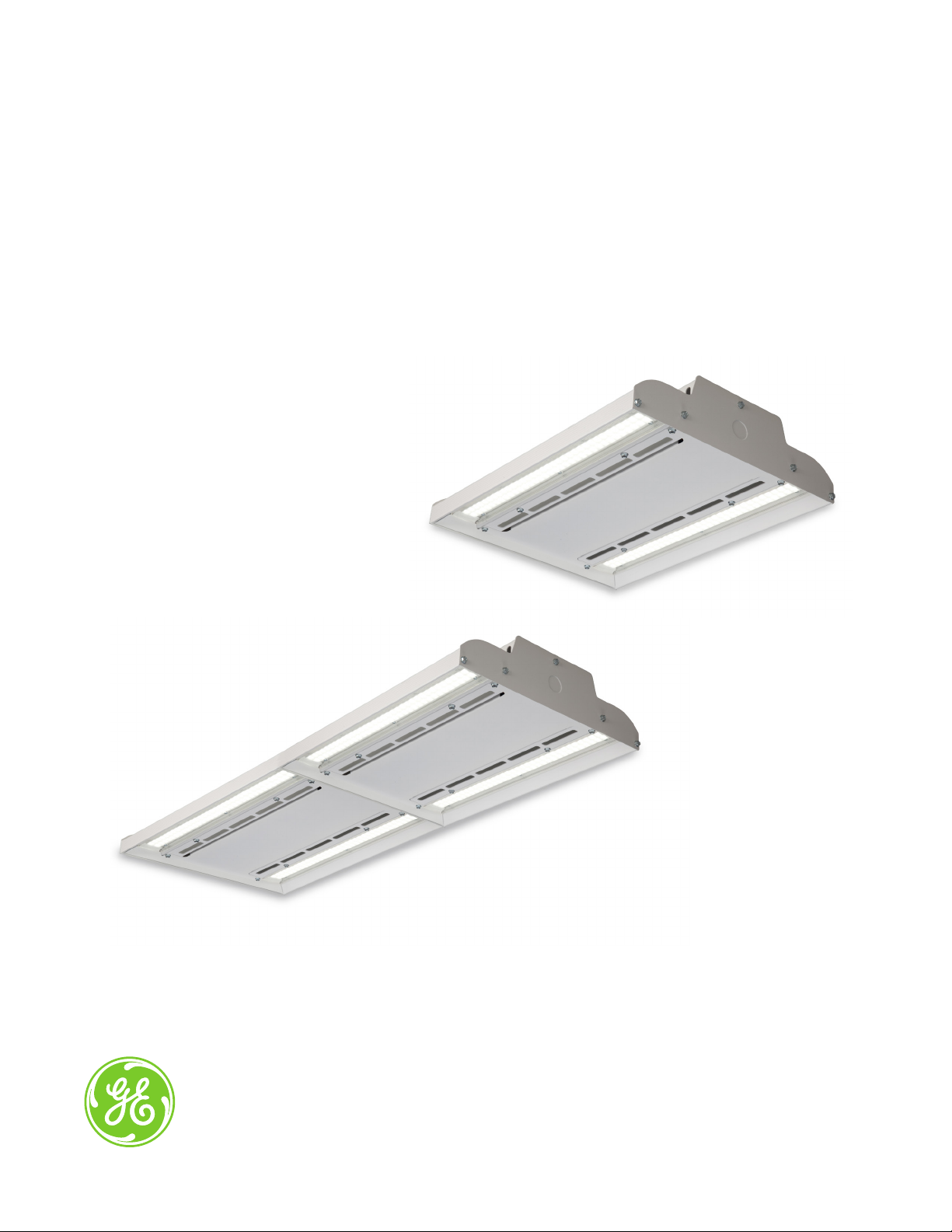
Albeo continues to build on the groundbreaking ABH-Series high bay LED luminaire with its latest high bay, the
ABV-Series. Utilizing a new form factor, the ABV-Series offers customers the best mixture of value and performance.
Applications
• Designed to meet recommended luminance and
illuminance requirements for High bay and Low
bay applications.
Housing
• Combination of steel and aluminum housing.
• ABV-Series’ design accommodates 1 or 2 modules
with 2 LED strips per module.
LED & Optical Assembly
• ABV-Series lens system enable LEDs to provide
optimized illumination for open floor and racked
aisles with photometric distributions of 55, 90
and 120 degrees.
• Utilizes high brightness LEDs, 70 CRI at 4000K &
5000K typical.
• LM-79, LM 80 tests and reports are performed in
accordance to IESNA standards.
Ratings
• DLC Listed
• RoHs
• UL 1598 Suitable for Damp Locations
/
• UL 8750 LED equipment in Lighting Products
• Temperature Rated at (–30°C to +55°C) (-22°F
to 131° F)
• Projected L70(8k) ≥ 100,000 Life Hours per
IES TM-21
Mounting
• Chain or Cable mounting ready, threaded rod kit,
and ¾” pendant mount kit optional
• Cord and plug options offered.
Finish
• Painted white finish
Controls
• Motion and Daylight sensor can be combined with
the ABV-Series for additional energy savings.
• For wireless controls please consult factory.
Electrical
• 120-277 volt, 347 and 480 volt available.
• System power factor is >90%* and THD <20%.*
• EMI: FCC CFR Title 47 Part 15, Class A.
* System power factor and THD is tested and specified at 120V
input and maximum load conditions.
Warranty
• 5-year limited system warranty standard.
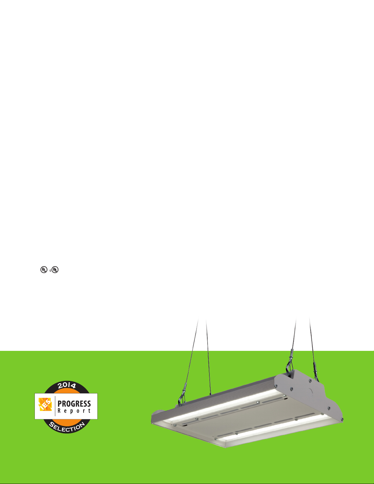
Industry Awards
Accepted for inclusion in the 2014 IES Progress Report.
Sponsored by the Illuminating Engineering Society.
Page 3

Ordering Number Logic
High Bay (ABV1)
A B V 1 V W
_ _ _ _ _ _ _ _ _ _ _ _ _ _ _ _ _ _
PRODUCT
A = Albeo
B = Bay
V = V-Series
1 = LED
Generation
MODULE
#
1 T 9000 9170 67 72 137 127
1 V 12080 12310 95 102 130 121
2 T 18000 18340 134 144 137 127
2 V 24160 24620 190 204 130 121
Note: Lumen data shown is for 120°(1) optic see table to the right for other light optic factors.
ID
VOLTAGE
(UL)
0 = 120/277
1 = 120*
2 = 208*
4 = 277*
5 = 480*
D = 347*
*Specify single
voltage if cord
and plug or
wireless needed.
OUTPUT
LEVEL
MODULE
1 = 1 module
2 = 2 modules
TYPICAL INITIAL
LUMENS 70 CRI
4000K 120V-277V 120V-277V5000K 347V-480V 347V-480V
T = Standard
V = Very High
Output
LUMEN
OUTPUT
LED COLOR
TEMP
70 Plus CRI
47 = 4000K
57 = 5000K
TYPICAL SYSTEM
WAT TS
OPTICS
BEAM
1 = 120°
5 = 55°
9 = 90°
D = 120°
Diffused lens
MOTION/DAYLIGHT
SENSOR
N = None
A = On/off aisle
motion
B = On/off 360
motion
C = On/off cold
temp aisle
D = On/off cold
temp 360
E = Daylight sensor
F = Aisle motion/
daylight
G = 360 motion/
daylight
H = Pre-wired
(no sensor)
J = 0-10V Motion 360
K = 0-10V Motion
aisle
L = 0-10V Motion
360 cold
M = 0-10V Motion
aisle cold
LPW (5000K)
CONTROL
WIRING
V = 0-10V
MOUNTING
ST = Standard
22 = 3/8” Threaded
rod mount kit
Rod and nuts not
included
23 = 3/4” Pendant
Mount Kit
3/4” condult not
included
41 = Y-Cable/
Hook 5 ft.
42 = Y-Cable/
Hook 10 ft.
43 = Y-Cable/
Hook 15 ft.
44 = Y-Cable/
Hook 20 ft.
See Mounting
& Accessories
OPTICS BEAM % OUTPUT
120° (1) 100%
55° (5) 93%
90° (9) 99%
120° Diffused (D) 99%
CORD
K = Knock out
access
A = 6 ft. 18-3
cord
B = 12 ft. 18-3
cord
Consult factory
for custom
cord lengths.
PLUG FINISH OPTIONS
N = None
A = 15A
straight plug
B = 20A
straight plug
C = 15A twist
lock plug
D = 20A twist
lock plug
Consult factory
for custom plugs.
W = White
Powder Coat
W = Wireless *
Consult factory
for wireless
configuration
* Wirelss not
available
with 347V-480V
Page 4

Photometrics
VA: 0° 10° 20° 30° 40°
g Criteria:
g Crit
Spacin
Spacin
S
0° = 1.29
0° =
90° =9=
g Criteria:
g Crit
Spacin
Spacin
S
0° = 1.30
0° =
90° =9=
g Criteria:
g Crit
Spacin
Spacin
S
0° = 1.29
0° =
90° =9=
Optics for Common Applications
Polar Candela Distribution
120° Full Beam Angle
VA: 0° 10° 20° 30° 40°
Polar Candela Distribution
90° Full Beam Angle
90°
80°
70°
60°
50°
90°
80°
70°
60°
Polar Candela Distribution
120° Diffused Full Beam Angle
Polar Candela Distribution
55° Full Beam Angle
Spacing Criteria:
0° = 1.33
90° = 0.87
90°
80°
70°
60°
50°
90°
80°
70°
60°
VA: 0° 10° 20° 30° 40°
50°
VA: 0° 10° 20° 30° 40°
50°
Lens selection by application
The Albeo™ ABV-Series optical lens system enables LEDs to provide precise illumination where needed. Lenses are designed
for commercial & industrial applications where mounting height, fixture spacing & light levels help determine lens selection.
The following table outlines lens options and suggested application. Consult factory for specific project layouts.
LENS TYPE SPACE TYPEMOUNTING HEIGHT
120º Diffused Below 20 Feet Open Floor Plan
120º Standard Any Open Floor Plan
90º Any Open Floor Plan
55º Any Low or High Bay Racked Aisles
Page 5

Mounting & Accessories
MOUNTING OPTIONS IMAGE ORDER LOGIC CODE
Mounting Holes
Standard Chain/Cable Mount
Available on all fixture configurations
(chain not included). Y-Cable w/hook can
be ordered as an accessory.
A
ST = Standard
Mounting Holes
Rod Mount (optional)
Available on all fixture configurations.
Attaches to 1/2” threaded rod (rod and
nuts not included).
Pendant Mount (optional)
Available on all fixture configurations.
Attaches to 3/4” threaded conduit
(conduit not included).
Y-Cable w/hook (optional)
Use with Standard Mounting Option only.
Order separately. Price adder per pair.
5 ft., 10 ft ., 15 ft ., 20 ft . lengths available.
Fasten with
nuts
Attach to
structural member
Attach to
structural member
22 = 1/2” Threaded Rod Kit
23 = 3/4” Pendant Mount Kit
41=Y-Cable-Hook-05ft-Pair
42=Y-Cable-Hook-10ft-Pair
43=Y-Cable-Hook-15ft-Pair
44=Y-Cable-Hook-20ft-Pair
Max Load: 200 lbs. per pair
Chain/cable mount is standard and included in price. Price adder for Y-Cable, Rod Mount, and Pendant Mount . Consult Sales for latest information.
See “Installation Instructions” for mounting details.
Page 6

Product Dimensions
High Bay (ABV1)
1-Module
11.625”
Max. Weight: 11 lbs.
2-Module
11.625”
15.06”
30.06”
Side View
11.625”
3.05”
www.gelighting.com
GE and the GE Monogram are trademarks of the General Electric Company. All other trademarks are the property
of their respective owners. Information provided is subject to change without notice. All values are design or typical
values when measured under laboratory conditions. GE Lighting and GE Lighting Solutions, LLC are businesses of
the General Electric Company. © 2015 GE.
ALB016 (Rev 01/13/15)
Max. Weight: 18 lbs.
 Loading...