

Page 1
GE
Lighting
™
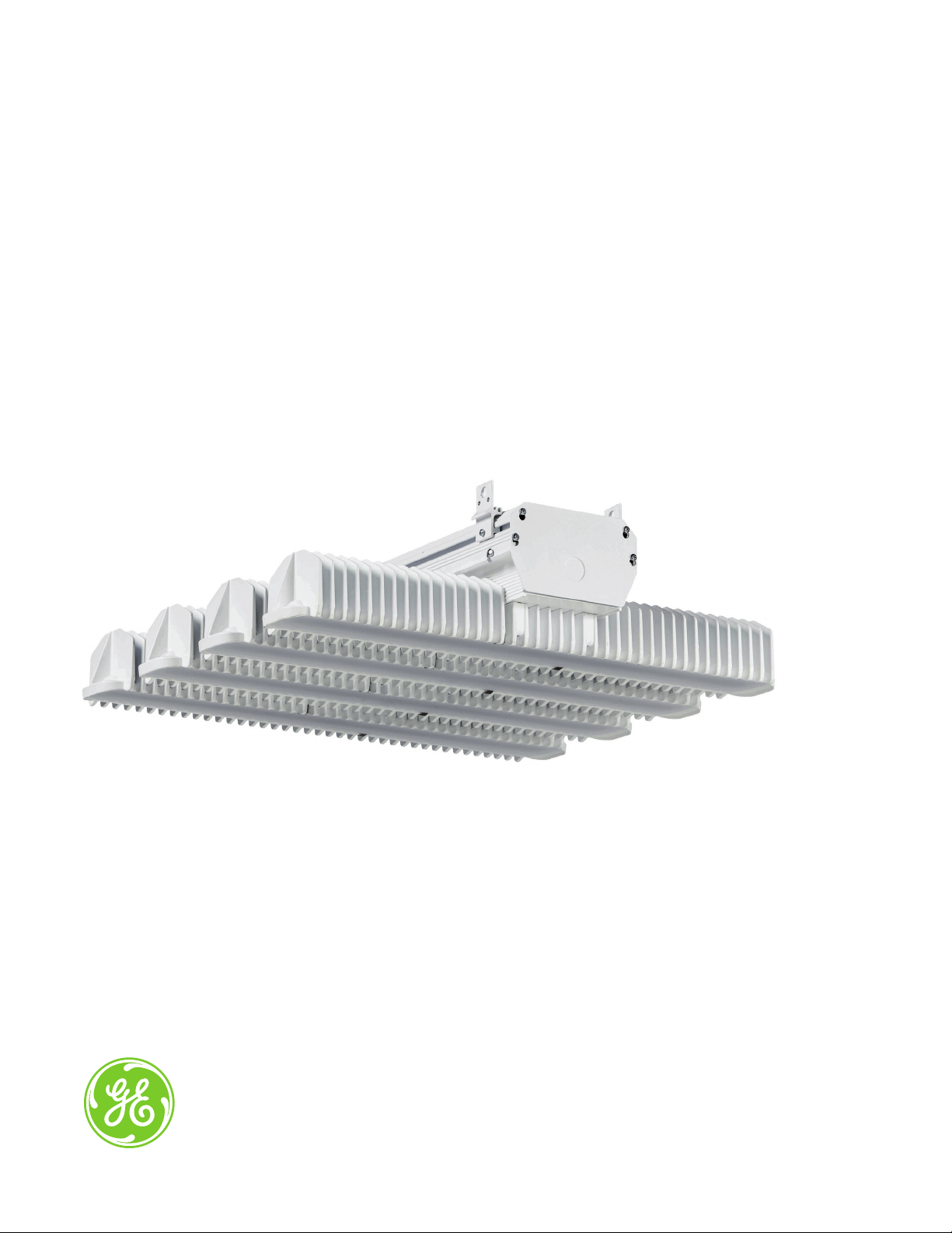
Albeo
Modular High & Low Bay Lighting
(ABHG - Series UL & CUL Certified)
LED Luminaire
imagination at work
Page 2
Product Features
®
Albeo continues to build on the groundbreaking award winning ABH-Series LED luminaire with its latest version, the
ABHG-Series. Utilizing the same innovative heat sinking and cutting edge LED technology but with improved electronics,
the HG series offers higher efficacy for new construction and retrofit applications . Combine all these great features
with controls technologies to deliver a high tech solution to High and Low bay applications.
Applications
• Designed to meet recommended luminance and
illuminance requirements for High bay and Low
bay applications
Housing
• Die cast aluminum housing.
• HG-Series’ innovative design accommodates up to
4 LED modules
LED & Optical Assembly
• HG-series lens system enable LEDs to provide
optimized illumination for open floor and racked aisles.
• Field upgradable lens and multiple photometric
distributions of 20, 30, 40, 80 and 120 degrees.
• Utilizes high brightness LEDs, 70 & 80 CRI at
4000K & 5000K typical.
• LM-79, LM 80 tests and reports are performed in
accordance to IESNA standards.
Ratings
•
DLC. Listed.
/
• Listed.
• UL 1598 Suitable for Damp Locations.
• UL 8750 LED equipment in Lighting Products.
• RoHs.
•
Temperature Rated:
– 120/277V (-35ºC to +55ºC) (-31ºF to +131ºF)
– 347/480V (-35ºC to +45ºC) (-31ºF to +113ºF)
•
Projected L70 (15K) > 100,000 Life Hours per IES TM-21.
•
40°C to 60°C (non-energized) and documented materials
list with mfgr’s allowed storage temperatures
Mounting
• Chain or Cable mounting ready. 1/2” threaded
rod kit, indirect mount, and 3/4” pendant
mount kit optional.
• Cord and plug options offered.
Finish
• Painted white finish.
Controls
• Motion and Daylight sensor can be combined
with the HG series for additional energy savings
• For wireless controls please consult factory.
Electrical
• 120-277 volt, 347 and 480 volt available.
• System power factor is >90%* and THD <20%.*
• EMI: Title 47 CFR 15 Class A.
* System power factor and THD is tested and specified at 120V
input and maximum load conditions.
Warranty
• 5-year limited system warranty standard.
Page 3
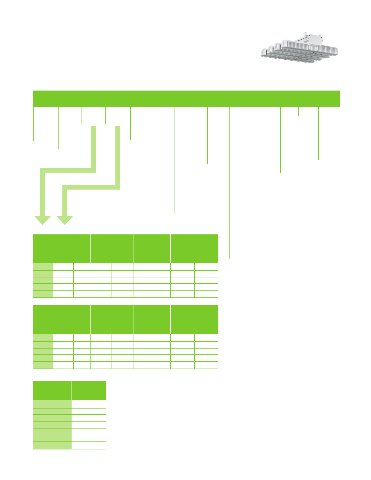
Ordering Number Logic
Scalable High Bay (ABHG-UL & CUL)
A B H G V W
_ _ _ _ - _ - _ - _ - _ _ - _ - _ - _ - _ _ - _ - _ - _ - _
PRODUCT
ID
A = Albeo
B = Bay
H = H-Series
G = Global
Specification
VOLTAGE
0 =
120/277
1 = 120*
4 = 277*
5 = 480*
D = 347*
*Specify single
voltage if
cord and plug
needed
MODULE
1 = 1 module
2 = 2 modules
3 = 3 modules
4 = 4 modules
DRIVE
CURRENT
T = Standard
H = High
Output
V = Very High
LED COLOR
TEMP
70 Plus CRI
47 = 4000K
57 = 5000K
80 Plus CRI
48 = 4000K
58 = 5000K
1 = 120°
2 = 20°
3 = 30°
4 = 40°
8 = 80°
D = 120°
Diffused lens
F = 30°
Diffused lens
OPTICS
BEAM
MOTION/DAYLIGHT
SENSOR
N = None
A = On/off
aisle motion
B = On/off
360 motion
C = On/off cold
temp aisle
D = On/off cold
temp 360
E = Daylight
sensor
F = Aisle motion
/daylight
G = 360 motion
/daylight
H = Pre-wired
(no sensor)
J = 0-10V
Motion 360
K = 0-10V
Motion aisle
L = 0-10V Motion
360 cold
M = 0-10V Motion
aisle cold
Available ABHG configurations:
TYPICAL INITIAL
MODULE#DRIVE
1 V 36 9,100 9,300 86 105 108
2 T 48 12,100 12,400 113 107 110
2 H 64 16,150 16,550 147 110 112
3 H 96 24,250 24,850 225 108 110
4 H 128 32,300 33,100 295 110 112
CURRENT
LED
COUNT
LUMENS 70 CRI
4000K 5000K
TYPICAL
SYSTEM WATTAGE
120-277V
347/480V
4000K
LPW
5000K
CONTROL
WIRING
V = 0-10V
Dimming
Note: 480V
motion is
on/off
only.
Note: No
0-10V Daisy
Chaining
with
347-480V
fixtures.
ST = Standard
22 = ½” Threaded
rod mount kit*
*Rod and nuts
not included
23 = ¾” Pendant
Mount Kit**
**Conduit not
included
UP = Indirect
Mount
41 = Y–Cable/
Hook 5 ft.
42 = Y-Cable/
Hook 10 ft.
43 = Y- Cable/
Hook 15 ft.
44 = Y- Cable/
Hook 20 ft.
61 = Indirect YCable/ Hook 5 ft.
62 = Indirect YCable/ Hook 10 ft.
63 = Indirect YCable/ Hook 15 ft.
64 = Indirect YCable/ Hook 20 ft.
See Mounting &
Accessories
Note:
IES files located
on GE website
www.gelighting.com
CORD
K = Knock out
access
A = 6 ft. 18-3
cord
B = 12 ft. 18-3
cord
Consult
factory for
custom cord
lengths.
PLUG
FINISH OPTIONSMOUNTING
N = None
W = White
A = 15A
Powder coat
Straight
Plug
B = 20A
Straight
Plug
C = 15A
Twistlock
Plug
D = 20A
Twistlock
Plug
Consult factory
for custom plugs.
*W = Wireless
Controls
*Please
consult
factory for
wireless
configuration
Note: Wireless
not available for
347V or 480V
fixtures.
TYPICAL INITIAL
MODULE#DRIVE
1 V 36 8,350 8,350 86 97 97
2 T 48 11,150 11,150 113 99 99
2 H 64 14,900 14,900 147 101 101
3 H 96 22,300 22,350 225 99 99
4 H 128 29,750 29,800 295 101 101
CURRENT
LED
COUNT
LUMENS 80 CRI
4000K 5000K
TYPICAL
SYSTEM WATTAGE
120-277V
347/480V
4000K
LPW
5000K
Note: Lumen data shown is for 120º (1) optic. See table below for other light optic factors.
OPTICS BEAM % OUTPUT
120° (1) 100.0 %
20° (2) 101.9 %
30° (3) 101.5 %
40° (4) 101.5 %
80° (8) 98.6 %
120° Diffused (D) 90.4 %
30° Diffused (F) 99.7 %
Page 4

Photometrics
a:
g Criter
.36
=
= 1.62
VA: 0° 10° 20° 30° 40°
r
g
.3
Optics for Common Applications
Aisle Distribution
20° Full Beam Angle
VA: 0° 10° 20° 30° 40°
Aisle Distribution
30° Diffuse Angle
90°
80°
70°
60°
50°
90°
80°
70°
Aisle Distribution
30° Full Beam Angle
90°
80°
70°
60°
50°
Narrow Distribution
40° Full Beam Angle
90°
80°
70°
VA: 0° 10° 20° 30° 40°
Standard Distribution
80° Full Beam Angle
VA: 0° 10° 20° 30° 40°
60°
50°
90°
80°
70°
60°
50°
60°
50°
VA: 0° 10° 20° 30° 40°
Standard/Diffused Distribution
120° Full Beam Angle
90°
80°
70°
60°
50°
VA: 0° 10° 20° 30° 40°
Page 5

Mounting & Accessories
MOUNTING OPTIONS IMAGE ORDER LOGIC CODE
Standard Chain/Cable Mount
Available on all fixture configurations
(chain not included). Y-Cable w/hook can
be ordered as an accessory.
Rod Mount (optional)
Available on all fixture configurations.
Attaches to 1/2” threaded rod (rod and
nuts not included).
Rod Mount Kit
ST = Standard
Mounting
Holes
Installed
22 = 1/2” Threaded Rod Kit
Pendant Mount (optional)
Available on all fixture configurations.
Attaches to 3/4” threaded conduit
(conduit not included).
Y-Cable w/hook (optional)
Use with Standard Mounting Option only.
Order separately. Price adder per pair.
5 ft., 10 ft ., 15 ft., 20 ft. lengths available.
Indirect Mount
Available on all fixture configurations
Installed
23 = 3/4” Pendant Mount Kit
Note: Cannot be used with 6 module High
Output or Very High Output fixture.
Pendant Mount Kit
41=Y-Cable-Hook-05ft-Pair
42=Y-Cable-Hook-10ft-Pair
43=Y-Cable-Hook-15ft-Pair
44=Y-Cable-Hook-20ft-Pair
Max Load: 200 lbs. per pair
UP=Indirect (No Y-Cable)
61=Indirect w/05ft Y-Cable
62=Indirect w/10ft Y-Cable
63=Indirect w/15ft Y-Cable
64=Indirect w/20ft Y-Cable
Max Load: 200 lbs. per pair
Chain/cable mount is standard and included in price. Price adder for Y-Cable, Rod Mount, Indirect Mount, and Pendant Mount. Consult Sales for latest information.
See “Installation Instructions” for mounting details.
Page 6

Product Dimensions
Scalable High Bay (ABHG-UL & CUL)
ABHG-Series
3.4”
1-Module (V)
7.7”
6.8”
3.6”
22.2”
21.3”
Max. Weight: 13 lbs. (5.9 kg)
21.31”
21.31”
15.5”
2-Module (T,H)
Max. Weight: 17 lbs. (7.7 kg)
21.31”
3-Module (H)
29.5”
Max. Weight: 31 lbs. (14.1 kg)
2, 3, 4-Module 120/277V, 347/480V
29.5”
4-Module (H)
Max. Weight: 36 lbs. (16.4 kg)
21.31”
5.25”
Page 7

Lens selection by application
The Albeo™ ABHG-series optical lens system enables LEDs to provide precise illumination where needed. Lenses are
designed for commercial & industrial applications where mounting height, fixture spacing & light levels help determine lens
selection. The following table outlines lens options and suggested application. Consult factory for specific project layouts.
LENS TYPE MOUNTING HEIGHT SPACE TYPE
Diffused 120° Below 20 Feet Open Floor Plan
Standard 120° Any Open Floor Plan
80° Any Open Floor Plan
40° Below 20 feet Low Bay Racked Aisles
30° Above 20 feet High Bay Racked Aisles
20° Above 20 feet High Bay Racked Aisles
Diffused 30° Below 20 feet Low Bay Racked Aisles
Page 8

www.gelighting.com
Albeo™, GE and the GE Monogram are trademarks of the General Electric Company. Information provided is subject
to change without notice. All values are design or typical values when measured under laboratory conditions.
GE Lighting Solutions, LLC is a subsidiary of the General Electric Company. © 2014 GE Lighting.
ALB012 (Rev 07/27/14)
 Loading...