

Page 1
Design Guide
with
In tall
In
36" Built-In Bottom-Freezer
Refrigerators
tructio
tion
monogram.com
Page 2

Safety Information
BEFORE YOU BEGIN
Read these instructions completely and carefullg.
. IMPORTANT- Savetheseinstructions
for local inspector's use. Observe all governing codes
and ordinances.
, Note to Installer - Be sure to leavethese
instructions with the Consumer.
, Note to Consumer- Keepthese instructions
with your Owner's Hanual for future reference.
WARNING:
This appliance must be properly grounded. See
"Grounding the Refrigerator," page 9.
AVERTISSEMENT
Cet appareil dolt _tre correctement mis 6 la terre.
Consulter << Mise 6 la terre du r_frig@ateur >>,page 9.
If you received a damaged refrigerator, you should
immediately contact your dealer or builder.
CAUTION:
Due to the weight and size of this refrigerator, and to
reduce the risk of personal injury or damage to the
product-THREE PEOPLEARE REQUIRED FOR PROPER
INSTALLATION.
PRUDENCE
#,cause du poids et de la taille de ce rBfrig@ator et pour
r_duire le risque de blessure et de dommages, IL FAUT
TROIS PERSONNES POUR FAIRE L'INSTALLATION
CORRECTEHENT.
Skill Level -Installation of this refrigerator requires
basic mechanical, carpentry and plumbing skills.
Proper installation is the responsibility of the installen
Product failure due to improper installation is not
covered under the GE Appliance Warranty. See the
Owner's Manual for warranty information.
WARNING:
o These refrigerators are top-heavy and must
be secured to prevent the possibility of tipping
forward. Anti-Tip protection is required. See page 11
for details.
, Use this appliance only for its intended purpose.
, Immediately repair or replace electric service cords
that become frayed or damaged.
, Unplug the refrigerator before cleaning or making
repairs.
Repairs should be made by a qualified service
technician.
AVERTISSEMENT
. Ces rBfrig@ateurs sont Iourds en haut et il faut
les arrimer pour _viter leur basculement. II faut avoir
un syst_me de protection contre le renversement.
Voir les d_tails page 11.
II ne faut utiliser cet appareil que pour I'utilisation
appropri_e.
R_parer ou remplacer imm_diatement tout cordon
_lectrique effiloch_ ou endommag_.
IIfaut d_brancher le r_frig@ateur avant le nettogage
ou toute intervention.
Les r¶tions doivent _tre faites par un technicien
qualifi_.
For Monogram local service in your area, call
1.800,444,1845.
For Monogram service in Canada, call
1.800.561.3344
For Monogram Parts and Accessories, call
1.800.626.2002.
www. monogram.cam
CONTENTS
Planning Guide
The Installation Space..............................3
Dimensions and Clearances ..................3
130° Door Swing ..........................................4
90° Door Swing ............................................5
Customization Basics................................B
Panel Dimensions ......................................7
Side Panels ....................................................8
ZUG2 Grille Panel Dimensions ..............8
Installation Instructions
Tools, Hardware, Haterials ....................9
Grounding the Refrigerator ....................9
Step 1,Remove Packaging ..................10
Step 2, Install Water Line ......................10
Step 2A, RO Water Line ........................11
Step 3, Install Side Panels ....................11
Step 4, Install Anti-Tip Brackets ........11
Step 5, Level Refrigerator ....................12
Step 6, Alternate Anti-Tip Procedure.._12
Step 7, Secure Refrigerator to
Cabinetry ......................................12
Step 8, Adjust Door Swing ....................13
Step 9, Install Grille Panel ....................13
Step 10, Install Framed Panels ..........14
Step 1OA, Install Overlay Panels ......15
Step 11, Connect Water Supply ........16
Step 12, Connect Power ........................16
Step 13, Start Icemaker ........................16
Step 14, Install Toekick ..........................17
Page 3
Design Guide
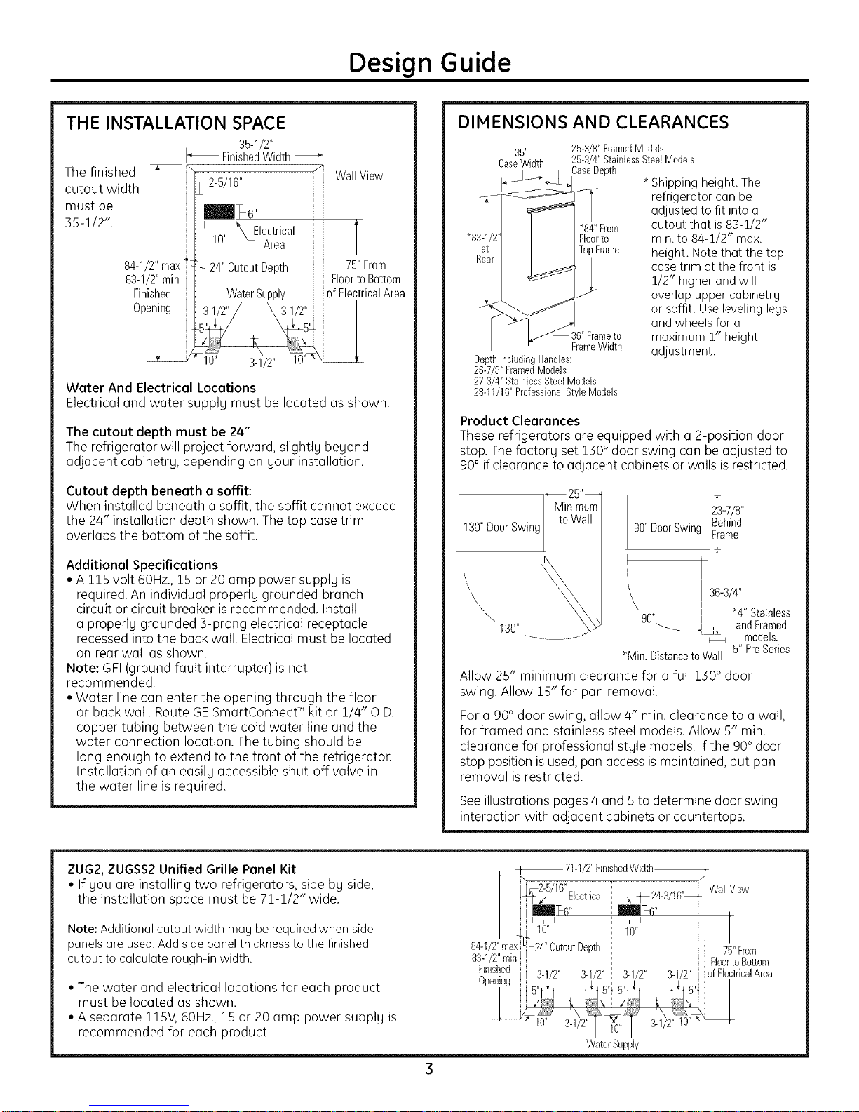
THE INSTALLATION SPACE
35-1/2"
FinishedWidth
The finished
cutout width
must be
B5-1/2".
84-1/2"max 75"From
83-1/2"min FloortoBottom
Finished of ElectricalArea
0per
Water And Electrical Locations
Electrical and water supply must be located as shown.
The cutout depth must be 24"
The refrigerator will project forward, slightly beyond
adjacent cabinetry, depending on your installation.
Cutout depth beneath a soffit:
When installed beneath a soffit, the soffit cannot exceed
the 24" installation depth shown. The top case trim
overlaps the bottom of the soffit.
Additional Specifications
• A 115 volt 60Hz.,15 or 20 amp power supply is
required. An individual properly grounded branch
circuit or circuit breaker is recommended. Install
a properly grounded 3-prong electrical receptacle
recessed into the back wall. Electrical must be located
on rearwallasshown.
Note:GFI(groundfaultinterrupter)isnot
recommended.
• Water linecan entertheopeningthroughthefloor
orbuckwall.RouteGE SmartConnectTM kitor1/4"O.D.
coppertubingbetweenthecoldwaterlineand the
waterconnectionlocution.The tubingshouldbe
long enough to extend to the front of the refrigeratoE
Installation of an easily accessible shut-off valve in
the water line is required.
WallView
DIMENSIONS AND CLEARANCES
35"
CaseWidth
,_ CaseDepth
T _84"From
"83-1/2" Floorto
at TopFlame
Rear m*
_._36"_ Frameto
r-
DepthIncludingHandles:
26-7/8"FlamedModels
27-3/4" Stainless Steel Models
28-11/16"ProfessionalStyleMe@is
Product Clearances
These refrigerators are equipped with a 2-position door
stop.The factory set 1BO° door swing can be adjusted to
90° if clearance to adjacent cabinets or walls isrestricted.
130"DoorSwing
'L
\,
\\
130°
......... J_
Allow 25" minimum clearance for o full 1BO° door
swing. Allow 15" for pan removal.
For o 90° door swing, allow 4" min. clearance to o wall,
for framed and stainless steel models. Allow 5" min.
clearance for professional style models. If the 90° door
stop position is used,pan access is maintained, but pan
removal is restricted.
Seeillustrations pages 4 and 5to determine door swing
interaction with adjacent cabinets or countertops.
25-3/8"FramedMe@is
25-3/4"StainlessSteelModels
FrameWidth
\
*Min. Distance to Wall
* Shipping height. The
refrigerator con be
adjusted to fit into o
cutout that is 83-1/2"
min. to 84-1/2" max.
height. Note that the top
case trim at the front is
1/2" higher and will
overlap upper cabinetry
or soffit. Use leveling legs
and wheels for o
maximum 1" height
adjustment.
23-7/8"
90°Door Swing Frame
90°
"_-.... ! andFramed
Behind
T
136-3/4"
I
I
*4" Stainless
5" ProSeries
models.
ZUG2,ZUGSS2Unified Grille Panel Kit
• If you are installing two refrigerators, side by side,
the installation space must be 71-1/2" wide.
Note: Additional cutout width may be required when side
panels are used. Add side panel thickness to the finished
cutout to calculate rough-in width.
• The water and electrical locations for each product
must belocated as shown.
• A separate 115V, 60Hz., 15 or 20 amp power supply is
recommended for each product.
84-1/2"max
83-1/2"rain
Finished
Opening
--- 71-1/2"FinishedWidth_
,_2-5/16" _ WallView
_F_[lectrJcal-_ _ 24-3/16"
10" 10"
-24" CutoutDepth
FloortoBottom
3-1/2" 3-1/2" 3q/2" 3-1/2"
ofElectricalArea
,_ 5,_5,,_
Water Supply
75"From
Page 4
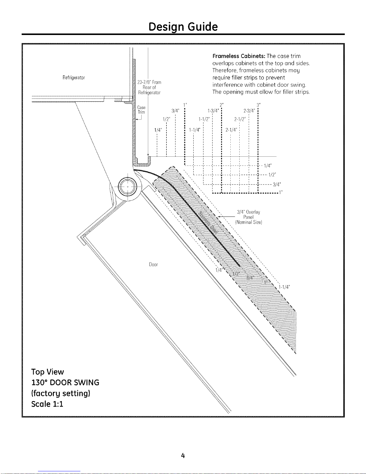
Refrigerator
Design Guide
23-7/8" From
Rearof
Refrigerator
Frameless Cabinets: The case trim
overlaps cabinets at the top and sides.
Therefore, fromeless cabinets mo U
require filler strips to prevent
interference with cabinet door swing.
The opening must allow for filler strips.
08se
Trim
1/4"
Door
1/2" ,'
i i
i i
1_' 2"
3/4"
i
1-1/4"
; I
I
1-3/4"
1-1/2"
"" 3/4" Overlay
2-3/4"
2q/2"
2-1/4"
Panel
"', (Nominal Size
Top View
130° DOOR SWING
(factory setting)
Scale i:I
I-1/4"
Page 5
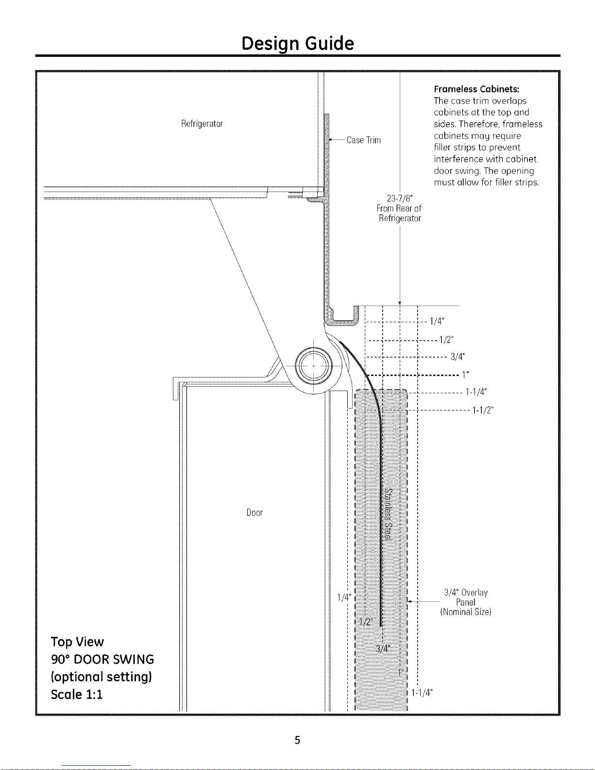
Refrigerator
Design Guide
CaseTrim
Frameless Cabinets:
The cose trim overlaps
cabinets at the top and
sides. Therefore, frameless
cabinets may require
filler strips to prevent
interference with cabinet
door swing. The opening
must allow for filler strips.
23-7/8"
FromRearof
Refrigerator
Top View
90° DOOR SWING
(optional setting)
Scale 1:1
Door
3/4"Overlay
Panel
(NominalSize)
1-1/4"
Page 6
Design Guide
CUSTOMIZATION BASICS:
Framed Or Overlag Panels, Custom Handles and Accessorg Kits
Professional Stgle Stainless Steel Refrigerators
Stainless steel wrapped refrigerators with beveled edges
and professional style handles. These models are shipped
ready for installation.
Stainless Steel Wrapped Refrigerators
Stainless steel wrapped refrigerators with beveled edges
and tubular stainless steel handles that coordinate with
other Monogram appliances. These models are shipped
ready for installation.
Trimmed Refrigerators
Trimmed refrigerators are designed to be customized with
decorative panels. Field installed custom door and grille
panels are required.
Framed panels
You may install 1/4" thick custom panels from your
cabinet manufactureE The decorative panel slides into the
factory installed trim. Or,order black, white and stainless
steel accessory panels from your Monogram dealeE
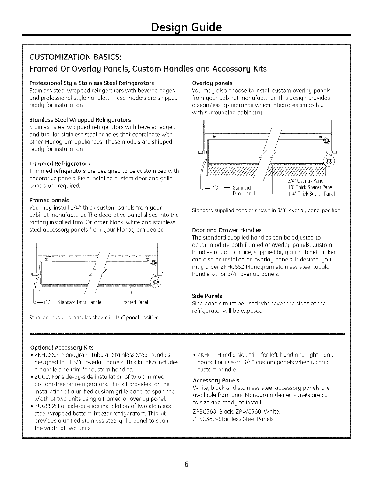
Overlay panels
You may also choose to install custom overlay panels
from your cabinet manufacturer. This design provides
a seamless appearance which integrates smoothly
with surrounding cabinetry.
yPanel
DoorHandle
Standard supplied handles shown in 3/4" overlay panel position.
-- 1/4"ThickBackerPanel
SpacerPanel
Door and Drawer Handles
The standard supplied handles can beadjusted to
accommodate both framed or overlay panels. Custom
handles of your choice, supplied by your cabinet maker
can also be installed on overlay panels. If desired, you
may order ZKHCSS2Monogram stainless steel tubular
handle kit for 3/4" overlay panels.
Framed Panel
Standard supplied handles shown in 1/4" panel position.
Optional Accessorg Kits
, ZKHCSS2:Monogram Tubular Stainless Steel handles
designed to fit 3/4" overlay panels.This kit also includes
a handle side trim for custom handles.
, ZUG2:For side-by-side installation of two trimmed
bottom-freezer refrigerators. Thiskit provides for the
installation of a unified custom grille panel to span the
width of two units using a framed or overlay panel.
ZUGSS2:For side-by-side installation of two stainless
steel wrapped bottom-freezer refrigerators. This kit
provides a unified stainless steel grille panel to span
the width of two units.
Side Panels
Side panels must be used whenever the sides of the
refrigerator will be exposed.
, ZKHCT:Handle side trim for left-hand and right-hand
doors. For use on 3/4" custom panels when using a
custom handle.
Accessory Panels
White, black and stainless steel accessory panels are
available from your Monogram dealer. Panels are cut
to size and reads to install.
ZPBC360-Black, ZPWC360-White,
ZPSC360-Stainless Steel Panels
Page 7

Design Guide
1/4" FRAMED PANEL DIMENSIONS
If you choose to install framed panels,they must be cut
to the dimensions shown. The panels will slide into the
frame on the door, drawer and grille.
If the custom panel is lessthan 1/4" thick and if it fits
loosely in the door frame, it can be backed upwith a
piece of filler material or foam tape to improve the fit.
I_A I
[ Grille Panel _
Framed Panel Dimensions
1/4" Framed Panel 33-7/8" 8-7/8" 46-1/16"
Door
\
\
\
IMPORTANT NOTE: Maximum total
panel weight:
• Fresh food door panel - 58 Ibs.
• Freezer drawer panel - 28 Ibs.
• Grille Panel - 11 Ibs.
A(Width) B(Grille Height) C(FF Height)
1_5/16"
Trim
Reveal
_,1/4"
Panel
D (FZ Height)
21-7/8"
Panel
FreshFood _
FreezerDrawer D
Panel
I
Overlay Panel Dimensions
1/4" Backer Panel 33-7/8" 8-7/8" 46-1/16"
0.10" Spacer Panel 32-1/2" 7-5/8" 44-11/16"
3/4" Overlay Panel 34-1/8" 9" 46-5/16"
3/4" OVERLAY PANEL DIMENSIONS
For a more custom appearance, overlay panels may be
installed on trimmed models. The overlay panel must be
secured to a 1/4" thick backer panel which slides into the
trim. A spacer panel 0.10" thick must be placed between
the overlay and backer panel.
Assemble the panels with glue and screws.
, Center the spacer panel on the backer panel, left to
right and top to bottom. Secure the panels with glue.
, Center the spacer and backer panel on the overlay
panel and secure with glue and screws. Screws must
be countersunk into the backer panel.
A (Width) B (Grille Height) C (FF Height)
Door/Drawer
\
\
i
t
1'/4"
Backer
Panel
_Spacer
D (FZ Height)
21-7/8"
20-1/2"
22"
IMPORTANT NOTE: Maximum
total weight for the assembled
panels:
• Fresh food door panel - 58 Ibs.
• Freezer drawer panel - 28 Ibs.
• Grille Panel - 11 Ibs.
NOTE: Left-to-right offset is not alwags equal to
top-to-bottom offset.
Page 8

Design Guide
SIDE PANELS
Side panels must be used whenever the sides of the
refrigerator will be exposed. The 1/4" side panels will
slip into the side case trim. Secure the panels to the
refrigerator with stick-on hook and loop fastener strips.
Order the side panels from the cabinet manufocture_
• Cut a notch in the top front corner as shown to allow
clearance for corner kegs in the front side trim.
* Depending on
installation height.
_84"
ZUG2 GRILLE PANEL DIMENSIONS
The ZUG2 unified grille panel kit provides for the
installation of o framed or overlag grille panel.
A
[ GrillePanel J_
Framed Panel Dimensions
A (Width) B (Height)
1/4" Framed Panel 69-7/8" 8-7/8"
Overlay Panel Dimensions
A (Width) B (Height)
1/4" Backer Panel 69-7/8" 8-7/8"
0.10" Spacer Panel 68-1/2" 7-5/8"
5/4" Overlag Panel 70-1/8" 9"
i i
i i i
Assemble the overlag panels in the some manner as
the door and drawer panels.
Page 9

Installation Instructions
TOOLS REQUIRED
, Tinsnips to cut banding
o Stepladder
Bucket
Level
Appliance Hand Truck
Tubing cutter
7/16" open-end wrench
#2 Phillips screwdriver
Drill and appropriate bits
5/!6", 7/16" socket
, Safety glasses
,1-1/4" open end wrench
o Pliers
,1/4" ratchet
HARDWARE SUPPLIED
, Water filter bypass plug
Anti-Tip brackets
!/4" nut and ferrule
MATERIALS REQUIRED
o 35" long 2x4 for Anti-Tip support
,1/4" copper water line tubing or GESmartConnect"
Refrigerator Tubing kits
, Water shut-off valve
, Custom panels for fresh food door, freezer drawer
and grille panel
Screws to secure refrigerator to cabinetry.
o Stick-on hook and loop fastener strips for
1/4" side panels
FLOORING
For proper installation, this refrigerator must be placed
on a level surface of hard material that is at the same
height as the rest of the flooring. Thissurface should
be strong enough to support a fully loaded refrigerator,
or approximately 1,200 Ibs.
NOTE:Protect the finish of the flooring. Cut a large
section of the cardboard carton and place under the
refrigerator where you are working.
GROUNDING THE REFRIGERATOR
IIPORTANT--{Please reed carefully)
FOR PERSONAL SAFETY,THIS APPLIANCE MUST BE
PROPERLYGROUNDED.
The power cord of this appliance is equipped with
a ]-prong (grounding) plug which mates with a
standard three-prong (grounding) wall receptacle
to minimize the possibility of electric shock hazard
from this appliance.
Have the wall outlet and circuit checked by a
qualified electrician to make sure the outlet is
properly grounded.
Where a standard 2-prong wall outlet is encountered, it
is your personal responsibility and obligation to have it
replaced with a properly grounded 3-prong wall outlet.
DO NOT, UNDER ANY
CIRCUMSTANCES, CUT
OR REMOVE THE THIRD
(GROUND) PRONG FROM
THE POWER CORD.
DO NOT USE AN ADAPTER PLUG TO CONNECT THE
REFRIGERATORTO A 2-PRONG OUTLET.
DO NOT USE AN EXTENSION CORD WITH THIS
APPLIANCE.
Page 10

Installation Instructions
ISTEP11REMOVE PACKAGING
CAUTION: Refrigerator is much heavier at the
top than at the bottom-be careful when moving. When
using u hand truck, handle from side only.
PRUD ENCE: Ler_frig_ruteur est beuucoup
plus Iourd en haut qu'en bus. II faut _tre prudent Iors
des d_placements. Si un diable est utilis_, il fuut soulever
le r_frig_rateur sur le c6t_ seulement.
• Corefully cut bonding ot the top and bottom,
remove outer carton.
• Slide out back corner posts (2).
• Slide carton off top of cabinet.
NOTE:ITISNOT NECESSARYTOLAYCABINETDOWN IN
ORDERTOREMOVESKID!
• The unit is secured to the skidwith 4 slotted
tie-down straps. Remove the four 5/16" bolts from the
bose channels in the tie-downs.
[STEP21INSTALL WATER LINE
J
• Remove the four 7/16"
bolts securing the straps
to the skid.
CAUTION: DoNOT
ATTEMPTTOROLLUNIT
OFFSKID.
Remove
Tie-Downs
J
• Support blocks on the bottom of the refrigeration
case must be removed before the refrigerator is
taken off the skid or damage will occur. Carefully,
tilt refrigerator and slide blocks out from beneath.
• Remove toekick. Set aside for final installation.
• Lift the refrigerator off the skid with on appliance
dolly. Handle from the sides.
PRUDENCE: ILNE
FAUTPASESSAYERDE FAIRE
ROULERLEREFRIGERATEUR
POURL'ENLEVERDELAY
PALETTE,
•A cold woter supply is required for outomotic
icemuker operation. Thewater pressure must be
between 40 and 120 p.s.i.
• Route 1/4" ODcopper or GESmurtConnect T"plastic
tubing between house cold water line and the water
connection location.
• Tubing should be long enough to extend to the front of
the refrigerator. Allow enough tubing to accommodate
bend leading into the water line connection.
NOTE:The only GE-opproved plastic tubing is supplied
in the GESmortConnecf" Refrigerator Tubing kits. Do not
use any other plastic water supply line because the line
is under pressure at all times. Other types of plastic may
crack or rupture with age and cause water damage to
your home.
GESmortConnect" Refrigerator Tubing Kits ore available
in the following lengths:
2' (.6 m) WXO8X10002
6' (1,8 m) WX08X10006
1S' (4.6m) WX08Xl0015
25' (7.6 m) WX08X10025
Shut off the main water supplg.
Turn on the neorest foucet long enough to cleor the line
of woter.
• Instoll o shut-off volve between the icemoker woter
volve ond cold woter pipe in o bosement or cobinet.
The shut-off volve should be Iocoted where it will be
eosily occessible.
\ WaterlineTubing
• Turn on the moin water supply ond flush debris.
Runabout a quart of water through the tubing into
a bucket. Shut off woter supply at the shut-off valve.
NOTE:Saddletype shut-off valvesare included in
many water supply kits,but ore not recommended
for this opplicotion.
NOTE:Commonweolth of MossochusettsPlumbing
Codes248CMR shollbe odhered to. Soddlevolves ore
illegol ond useis not permitted in Mossochusetts.
Consultwith your licensedplumbeE
10
Page 11

Installation Instructions
ISTEP 2AIWATERLINE INSTALLATIONWITH
A REVERSEOSMOSIS SYSTEM
Skipthis step when not using an ROSgstem
If the water supply to the refrigerator is from aReverse
OsmosisWater System,usethe refrigerator's filter bypass
plug.Using the refrigerator's water filtration cartridge with
the ROfilter can result inhollow icecubes.
\
FilterBypassPlug
ISTEP 31 INSTALLSIDEPANELS
Skipthis stepwhennot usingsidepanels
Ifyouareusing1/4"sidepanels,theyshouldbeinserted
intothe casetrim.Fastenthe panelsto the refrigerator
with stick-onhookandloopfastenerstripsbeforesetting
refrigeratorin place.
ISTEP41INSTALLANTI-TIPBRACKETS
WARNING:ANTI-TIPPRECAUTIONS
Therefrigeratoristop-heavyandmustbesecuredto preventthe
possibilityoftippingforward.
ATTENTION:PRECAUTIONSCONTRELES
BASCULEMENTS
LerdrigerateurestbeaucoupplusIourdenhautetilfaut le
maintenirenplacepour_viterla possibilit_desonbasculement
versI'avant.
• Cuta 2" x4" x 35" blockandsecuretheblocktothe
mountingbracketsprovidedusing#12or#14wood screws.
2x4But J-_
35"Length
Installation Mounting
Height Bracket
FromFloor
ScrewsMountedinto_'_
VerticalWall Studs
• Securethebracketwithwood blockto the backwall sothat it is
84"(oryourinstallationheight)fromthe finishedfloor.Use#12
or#14woodscrews.Seeillustration.
Brackets
Required
Block.
Height
From
Floor
to
Bottom
ofWood
Block
Brackets
NotRequired
Beneatha
Soffit
SideView
• Screwsmustpenetrateat leastoneinchinto verticalwallstuds.
• Beforepushingthe refrigeratorintotheopening,plugthepower
cordintothereceptacle.Openthegrillepanelandreachinto
theopeningat the backto graspthepowercord.Pullthe power
cordintotheopeningasyou pushthe refrigeratorback.
• Gentlypushrefrigeratorintotheopeningwithhandsagainst
frontcorners.
Important Note: When the refrigerator isinstalled under a soffit or if
there isnot enough height for this method of security, brackets cannot
be used.Proceed to step 5 to level the refrigerator and then to step 6
to secure refrigerator to cabinets. Therefrigerator must be secured to
prevent tipping.
11
Page 12

Installation Instructions
[STEP S] LEVEL REFRIGERATOR
All models have 4-point leveling. The front is supported
bg leveling legs,the rear is supported bg adjustable
wheels. Both are accessible from the front of the
refrigerator.
• To level the back of the refrigerator, turn the 7/16" hex
nut located above the front wheels. Turn clockwise to
raise or counterclockwise to lower the refrigerator.
• For front leveling, use a !-!/4" open-end wrench.
• Adjust height of refrigerator to match installation
cutout opening 83-!/2 to 84-1/2". The refrigerator
should be level and plumb with cabinetrg.
HexNutAdjusts_--_4 El E
RearWheels
CAUTION:
The rear leveling wheels and front leveling legs are
limited to a maximum height adjustment of 1" Ifthe
installation requires more than 84-1/2" height, the
installer should elevate the refrigerator on a sheet
of plgwood or runners. Cabinetrg trim could also be
added across the top of the opening to shorten the
opening. If gou attempt to raise the refrigerator more
than 1", gou will damage the front leveling legs and
the rear leveling wheels.
ISTEP61ALTERNATEANTI-TIP
PROCEDURE
The refrigerator must be secured to prevent tipping.
The anti-tip brackets cannot be used on metal wall
studs. Use this Alternate Procedure to secure the
refrigerator against tip-over whenever metal wall
studs are encountered and there is no soffit.
SideView
TopCaseTrim
/
i I I
! i !
InstallFour
1-1/2"DrywallScrews
ThroughTrimandIntoSoffit
or3/4" Min.Wood Brace
• Raisethe grille panel to access case trim.
• Usea 3/16" bit to drill four evenlg spaced clearance
holes through the metal top case trim.
• Use a 1/16" bit to drill to pilot holes through the metal
clearance holes and into the wood soffit. The holes
should be centered in the soffit or a 3/4" min. wood
brace. The brace spanning the enclosure must be
securelg fastened to cabinets on both sides.
• Install four, 1-1/2" drgwall screws into the pilot holes.
PRUDENCE
Les roues de nivellement arri@reetles pattes de
nivellement avant permettent un r@glagemaximal
de 25 mm (1po). Si I'ouverture pour le r@frig@rateur
a une hauteur sup@rieure(_2,15 m (84-1/2 po),
I'installateur doit @leverle r@frig@rateursur une feuille
de contre-plaqu@ ou des glissi@res.II est @galement
possible d'ajouter des baguettes de finition des
placards sur le haut de I'ouverture afin de la r@duire.
Lever le r@frig@rateurde plus de 25 mm (1 po)
endommage les pattes de nivellement avant
etles roues de nivellement arri@re.
ISTEP 7 ISECUREREFRIGERATOR
TO CABINETRY
Whenever possible, perform this step for anti-tip
securitg, or when anti-tip brackets cannot be used.
The refrigerator must be secured to prevent tipping.
• Raisethe grille panel to access case trim.
• Drill hole in trim and drive screw through the trim into
adjacent cabinet.
• Follow the same procedure on the opposite side.
DriveScrews
Through CaseTrimandInto
Adjacent Cabinets
12
Page 13

Installation Instructions
[STEP 8 lAD JUST DOOR SWING
NOTE: This refrigerator has a 2-position door stop.
When space does not allow the door to swing open
fullu to 130°, Uou may change the door swing to a 90 °
opening. Skip this step if door opening is satisfactory
for gour instelletion situetion.
• Lift the grille panel to access the wire cover trim.
• Remove screws on both sides of the wire cover trim
and lift oft
• Use pliers to unscrew door stop and reinstall into the
90° position.
L_
Remove
WireCover
TrimScrews
PinLocationFor
90° Door_
Pin Location
as Shipped
130° Door Swing
J
INSTALL GRILLE PANEL
• Raise the grille panel to stop position.
I
Loosen !
Side ,
Trim
Screw
F
• Loose screws on side trim behind frame. Remove
bottom trim.
• Slide panel over the metal backer panel and into
the trim.
• If necessaru, tap with a wood block until panel slips
under the top trim piece.
• Reassemble bottom trim. Tighten screws.
• Adjust the hinge spring to accommodate the panel
weight, if necessaru.
, --_ Panne/_
AdjustNutBelow
Springto Accommodate
PanelWeight
GrilleJ|_
Loosen
Side
Trim
Screw
• Reinstall the wire cover trim.
13
Page 14

Installation Instructions
,ISTEP 101 INSTALL 1/4" FRAMED PAN ELS Righthand models shown. Use the same instructions
for left hand models.
IF YOU ARE INSTALLINGOVERLAYPANELS,
GO TO STEP10A.
UseFrontHoles
to SecureTrim
UseRearHoles
to SecureHandle
Handle
Trim
Standard supplied handle shown
in 1/4" panel position.
DoorTrim
Refrigerator
Door
Install door and drawer panels:
• Open door to 90°. Remove the 4 Phillips head screws
from the door handle.
• Remove handle. Retain all screws.
• Remove 4 screws holding trim, lift off trim.
Retain screws.
• Slide framed panel into the door trim.
• There are two sets of holes in the handle side trim.
Replace handle side trim bu installing the original screws
in the FRONTscrew holes.
• Secure the handle to the door using the REAR
screw holes.
• Follow the same procedures to install the drawer panel.
14
Page 15

Installation Instructions
[STEP IOA] INSTALL OVERLAY PANELS Right hand models shown. Use the same instructions
for left hand models.
DoorTrim
T
Handle
i
Trim
Refrigerator
Door
Move
Forward
For3/4"
Panel
ii!i!!i!i!iiiii!!!!!i
-UseFrontHoles
to SecureHandle
UseRearHoles
to SecureTrim
Supplied handle shown in the
overlay panel position.
Install door and drawer panels:
, Open door to 90°. Remove the 4 Phillips head screws
from the door handle.
, Remove handle. Retain all screws.
, Remove a screws holding trim. lift off trim.
Retain screws.
, Slideoverlay panel into the door trim.
Custom handles
If you ore using custom handles, the handle must be
properly secured to the panel before sliding the panel
into the trim.
, The cabinet manufacturer will supply the custom
handle and hardware.
, Secure the door/drawer trim using both the FRONT
and REARscrew holes. Discord supplied handle.
, There are two sets of holes in the handle side trim.
Replace handle side trim by installing the original screws
in the REARscrew holes.
, Secure the handle to the door using the FRONT
screw holes.
, Follow the same procedures to install the drawer panel.
15
Page 16

Installation Instructions
[STEP11ICONNECTWATERSUPPLY
WaterSupply
o Locate and bring tubing to the front of the cabinet.
Turn the water on to flush debris from line. Run about
a quart of water through tubing into a bucket, then
shut off water.
Copper Tubing:
Slip a 1/4" nut and ferrule (provided) over both ends
of the copper tubing. Insert tube into the union fitting
on the unit and tighten nutto union.
Turn on the water to check for leaks.
ISTEP12ICONNECTPOWER
, Check to be sure the power cord is plugged into the
receptacle.
Grille_!
:L.
__ Panel _
\
Electrical Master Light
Outlet Switch
, Check to make sure power to refrigerator ison
bu opening refrigerator door to see if interior lights
are on.
, The temperature controls ore preset at 37°F
for the fresh food section and 0°Ffor the freezen
, Allow 24 hours to stabilize before making
adjustments.
ISTEP 131STARTICENAKER
RaiseIN
GESmartConnect T"Tubing:
Insert the molded end of the tubing into the
refrigerator connection. Tighten the compression nut
until it is just hand tight.
Tighten one additional turn with a wrench.
Overtightening can cause leaks!
Turn on the water to check for leaks.
Note: Make sure excess tubing length does not
interfere with drawer closing or toekick installation.
o Flipthe switch to I (ON).The icemaker will begin
operation automaticallu.
, Be sure nothing interferes with the sweep of
the feeler arm.
, Discard the first full bucket of ice cubes.
, To turn the icemaker off, set the switch to O (OFF).
16
Page 17

Installation Instructions
ISTEP141INSTALL TOEKICK
, Locate the supplied toekick (shipped taped to
the side of the refrigerator). Install with 2 screws
provided, adjust to desired height and tighten screws.
, A custom toekick can be installed to match or
complement the surrounding cabinetrg. Usethe
supplied toekick as a template to cut out the notch
and vent holes.
SuppliedToel<ick
1/4"orThickerToel<icl<
Important: The vented toekick must remain
unobstructed for proper air circulation and
refrigerator operation.
17
Page 18

Notes
18
Page 19

Notes
19
Page 20

NOTE: While performing installations described in this book,
safetg glasses or goggles should be worn.
For Monogram ®local service in your area, call
1.800.444.1845.
NOTE: Product improvement is a continuing endeavor
at General Electric. Therefore, materials, appearance and
specifications are subject to change without notice.
No. 49-60468-1
No. 224D1145P001
08-07 JR
GE Consumer & Industrial
Appliances
General Electric Compang
Louisville, KY40225
ge.com
 Loading...