

Page 1

GE
LISTED
52TL
IND.CONT. EQ.
E83849
Grid Solutions
350
Feeder Protection System
Feeder protection and control
Instruction manual
350 revision: 2.3x
Manual P/N: 1601-9086-AN
GE publication code: GEK-113507W
*1601-9086-AN*
Page 2

© 2017 GE Multilin Inc. All rights reserved.
GE Multilin Inc. 350 Feeder Protection System instruction manual for revision 2.3x.
350 Feeder Protection System, EnerVista, EnerVista Launchpad, and EnerVista 3 Series
Setup are trademarks or registered trademarks of GE Multilin Inc.
The contents of this manual are the property of GE Multilin Inc. This documentation is
furnished on license and may not be reproduced in whole or in part without the permission
of GE Multilin Inc. The content of this manual is for informational use only and is subject to
change without notice.
Part number: 1601-9086-AN (June 2017)
Storage
Store the unit indoors in a cool, dry place. If possible, store in the original packaging. Follow
the storage temperature range outlined in the Specifications.
To avoid deterioration of electrolytic capacitors, power up units that are stored in a deenergized state once per year, for one hour continuously.
This product cannot be disposed of as unsorted municipal waste in the European
Union. For proper recycling return this product to your supplier or a designated
collection point. For more information go to www.recyclethis.info.
Page 3

Note
GENERAL SAFETY PRECAUTIONS - 350
• Failure to observe and follow the instructions provided in the equipment manual(s)
could cause irreversible damage to the equipment and could lead to property
damage, personal injury and/or death.
• Before attempting to use the equipment, it is important that all danger and caution
indicators are reviewed.
• If the equipment is used in a manner not specified by the manufacturer or
functions abnormally, proceed with caution. Otherwise, the protection provided by
the equipment may be impaired and can result in Impaired operation and injury.
• Caution: Hazardous voltages can cause shock, burns or death.
• Installation/service personnel must be familiar with general device test practices,
electrical awareness and safety precautions must be followed.
• Before performing visual inspections, tests, or periodic maintenance on this device
or associated circuits, isolate or disconnect all hazardous live circuits and sources
of electric power.
• Failure to shut equipment off prior to removing the power connections could
expose you to dangerous voltages causing injury or death.
• All recommended equipment that should be grounded and must have a reliable
and un-compromised grounding path for safety purposes, protection against
electromagnetic interference and proper device operation.
• Equipment grounds should be bonded together and connected to the facility’s
main ground system for primary power.
• Keep all ground leads as short as possible.
• At all times, equipment ground terminal must be grounded during device
operation and service.
• In addition to the safety precautions mentioned all electrical connections made
must respect the applicable local jurisdiction electrical code.
• Before working on CTs, they must be short-circuited.
• LED transmitters are classified as IEC 60825-1 Accessible Emission Limit (AEL) Class
1M. Class 1M devices are considered safe to the unaided eye. Do not view directly
with optical instruments.
• This product uses optical electronic devices (line or point sensors) to sense arc
flash fault conditions. It is recommended to follow proper housekeeping measures
and establish a regularly scheduled preventive maintenance routine to ensure
proper device operation.
• This product itself is not Personal Protective Equipment (PPE). However, it can be
used in the computation of site-specific arc flash analysis when the arc flash
option is ordered. If a new appropriate Hazard Reduction Category code for the
installation is determined, the user should follow the cautions mentioned in the arc
flash installation section.
• This guide is intended to provide protective relay application guidance to mitigate
arc flash incident energy. This guide does not endorse energized work. This guide
does not claim that protective relaying can totally protect personnel from the
dangers of an arc flash. The only way to completely prevent injury from arc flash
events is to de-energize the equipment and properly follow safe lockout/tagout
procedures to ensure the equipment remains de-energized.
Page 4

Safety words and definitions
The following symbols used in this document indicate the following conditions
Note
Indicates a hazardous situation which, if not avoided, will result in death or serious
injury.
Note
Indicates a hazardous situation which, if not avoided, could result in death or serious
injury.
Note
Indicates a hazardous situation which, if not avoided, could result in minor or
moderate injury.
Note
Indicates practices not related to personal injury.
For further assistance
For product support, contact the information and call center as follows:
GE Grid Solutions
650 Markland Street
Markham, Ontario
Canada L6C 0M1
Worldwide telephone: +1 905 927 7070
Europe/Middle East/Africa telephone: +34 94 485 88 54
North America toll-free: 1 800 547 8629
Fax: +1 905 927 5098
Worldwide e-mail: multilin.tech@ge.com
Europe e-mail: multilin.tech.euro@ge.com
Website: http://www.gegridsolutions.com/multilin
Page 5

Table of Contents
1. INTRODUCTION Overview ................................................................................................................................1 - 1
Description of the 350 Feeder Protection System..............................................1 - 2
350 order codes..................................................................................................................1 - 5
Specifications.......................................................................................................................1 - 9
Password security....................................................................................................................1 - 9
Protection.....................................................................................................................................1 - 9
Metering........................................................................................................................................1 - 14
Data capture ..............................................................................................................................1 - 14
Control...........................................................................................................................................1 - 15
Monitoring....................................................................................................................................1 - 17
Inputs .............................................................................................................................................1 - 17
Outputs..........................................................................................................................................1 - 18
Power supply..............................................................................................................................1 - 20
Communications ......................................................................................................................1 - 21
Testing and certification .......................................................................................................1 - 22
Physical.........................................................................................................................................1 - 23
Environmental............................................................................................................................1 - 24
2. INSTALLATION Mechanical installation ...................................................................................................2 - 1
Dimensions..................................................................................................................................2 - 2
Product identification .............................................................................................................2 - 4
Mounting ......................................................................................................................................2 - 4
Standard panel mount.........................................................................................................2 - 4
Mounting using the S1/S2/MDP/IAC or SR735 adapter plate............................2 - 8
Drawout unit withdrawal and insertion.........................................................................2 - 11
IP20 Cover (optional) ...............................................................................................................2 - 12
Arc flash sensors.......................................................................................................................2 - 13
Sensor fiber handling & storage......................................................................................2 - 14
Point sensor installation......................................................................................................2 - 15
Loop sensor installation.......................................................................................................2 - 19
Electrical installation ........................................................................................................2 - 22
Typical wiring diagrams........................................................................................................2 - 23
350 Terminal identification..................................................................................................2 - 25
Wire range...................................................................................................................................2 - 28
Phase sequence and transformer polarity ..................................................................2 - 28
Current inputs ............................................................................................................................2 - 29
Ground and sensitive ground CT inputs ........................................................................2 - 29
Zero sequence CT installation ............................................................................................2 - 30
Voltage inputs............................................................................................................................2 - 31
Control power ............................................................................................................................2 - 31
Contact inputs ...........................................................................................................................2 - 32
Trip and Close output relays...............................................................................................2 - 33
Serial communications ..........................................................................................................2 - 35
IRIG-B .............................................................................................................................................2 - 36
3. INTERFACES Front control panel interface........................................................................................3 - 2
Description ..................................................................................................................................3 - 3
Display...........................................................................................................................................3 - 4
Working with the Keypad...................................................................................................3 - 4
350 FEEDER PROTECTION SYSTEM – INSTRUCTION MANUAL i
Page 6

LED status indicators - Front panel with non-programmable LEDs................3 - 6
LED status indicators - Front panel with programmable LEDs .......................... 3 - 7
Relay messages........................................................................................................................ 3 - 8
Target messages.....................................................................................................................3 - 8
Self-test errors..........................................................................................................................3 - 8
Flash messages.......................................................................................................................3 - 10
Software setup....................................................................................................................3 - 11
Quick setup - Software interface...................................................................................... 3 - 11
EnerVista 3 Series Setup Software................................................................................... 3 - 12
Hardware and software requirements.........................................................................3 - 12
Installing the EnerVista 3 Series Setup software......................................................3 - 12
Upgrading the software.......................................................................................................3 - 15
Connecting EnerVista 3 Series Setup to the relay ...................................................3 - 15
Configuring serial communications...............................................................................3 - 15
Using the Quick Connect feature....................................................................................3 - 16
Configuring Ethernet communications........................................................................3 - 17
Connecting to the relay.......................................................................................................3 - 18
Working with setpoints and setpoint files .................................................................... 3 - 19
Engaging a device..................................................................................................................3 - 19
Entering setpoints...................................................................................................................3 - 19
Setting programmable LEDs..............................................................................................3 - 21
File support ................................................................................................................................3 - 22
Using setpoint files.................................................................................................................3 - 22
Downloading and saving setpoint files ........................................................................3 - 23
Adding setpoint files to the environment....................................................................3 - 23
Creating a new setpoint file...............................................................................................3 - 24
Upgrading setpoint files to a new revision .................................................................3 - 25
Printing setpoints and actual values.............................................................................3 - 26
Printing actual values from a connected device.....................................................3 - 26
Loading setpoints from a file.............................................................................................3 - 27
Uninstalling files and clearing data................................................................................3 - 27
Upgrading relay firmware ...................................................................................................3 - 28
Loading new relay firmware.............................................................................................3 - 28
Advanced EnerVista 3 Series Setup features.............................................................. 3 - 30
Flexcurve editor.......................................................................................................................3 - 30
Transient recorder (Waveform capture).......................................................................3 - 31
Protection summary .............................................................................................................3 - 34
Password security..................................................................................................................3 - 36
4. ACTUAL VALUES Actual values overview ...................................................................................................4 - 1
A1 Status................................................................................................................................4 - 2
Clock............................................................................................................................................... 4 - 2
Contact inputs ...........................................................................................................................4 - 2
Output relays .............................................................................................................................4 - 2
Logic elements ..........................................................................................................................4 - 3
Virtual inputs ..............................................................................................................................4 - 3
Remote inputs ........................................................................................................................... 4 - 3
Remote outputs ........................................................................................................................4 - 3
Contact inputs summary ..................................................................................................... 4 - 3
Output relays summary ....................................................................................................... 4 - 4
Logic elements summary .................................................................................................... 4 - 4
GOOSE status............................................................................................................................. 4 - 4
GOOSE HDR status ..................................................................................................................4 - 5
61850 status ..............................................................................................................................4 - 5
RTC Sync Source ...................................................................................................................... 4 - 5
Redundancy ...............................................................................................................................4 - 5
ii 350 FEEDER PROTECTION SYSTEM – INSTRUCTION MANUAL
Page 7

IEEE 1588 PTP (Precision Time Protocol) ........................................................................4 - 6
A2 Metering...........................................................................................................................4 - 7
Current...........................................................................................................................................4 - 7
Voltage ..........................................................................................................................................4 - 8
Power .............................................................................................................................................4 - 9
Energy ...........................................................................................................................................4 - 9
Current Demand.......................................................................................................................4 - 10
Power Demand..........................................................................................................................4 - 10
Thermal capacity .....................................................................................................................4 - 11
Clear energy ...............................................................................................................................4 - 11
Clear current demand ...........................................................................................................4 - 11
Clear power demand..............................................................................................................4 - 11
A3 Records ............................................................................................................................4 - 12
Event records .............................................................................................................................4 - 12
Transient records .....................................................................................................................4 - 14
Fault report..................................................................................................................................4 - 14
Clear event record ...................................................................................................................4 - 15
Clear transient record ............................................................................................................4 - 15
Clear thermal capacity record...........................................................................................4 - 15
Clear fault report ......................................................................................................................4 - 16
A4 Target messages.........................................................................................................4 - 17
5. QUICK SETUP -
Quick Setup settings.........................................................................................................5 - 2
FRONT CONTROL
PANEL
6. SETPOINTS Setpoints Main Menu........................................................................................................6 - 1
Setpoint entry methods ........................................................................................................6 - 3
Common setpoints .................................................................................................................6 - 3
Logic diagrams..........................................................................................................................6 - 4
Setting text abbreviations ....................................................................................................6 - 5
S1 Relay setup.....................................................................................................................6 - 6
Clock...............................................................................................................................................6 - 6
350 Real Time Clock...............................................................................................................6 - 8
Password security....................................................................................................................6 - 9
Access passwords..................................................................................................................6 - 10
Communications ......................................................................................................................6 - 12
RS485 interface .......................................................................................................................6 - 12
Ethernet.......................................................................................................................................6 - 12
Redundancy mode 13
Modbus........................................................................................................................................6 - 14
IEC 60870-5-103 serial communication......................................................................6 - 15
IEC60870-5-104 protocol....................................................................................................6 - 15
DNP communication.............................................................................................................6 - 16
3 Series IEC 61850 GOOSE details...................................................................................6 - 16
OPC-UA Settings......................................................................................................................6 - 17
Event recorder ...........................................................................................................................6 - 18
Transient recorder ...................................................................................................................6 - 19
Fault report..................................................................................................................................6 - 21
Front panel with non-programmable LEDs .................................................................6 - 22
Front panel with programmable LEDs ...........................................................................6 - 22
Installation...................................................................................................................................6 - 24
S2 System Setup ................................................................................................................6 - 25
350 FEEDER PROTECTION SYSTEM – INSTRUCTION MANUAL iii
Page 8

Current sensing......................................................................................................................... 6 - 25
Voltage sensing ........................................................................................................................ 6 - 26
Power system............................................................................................................................6 - 28
Breaker.......................................................................................................................................... 6 - 28
User curve ................................................................................................................................... 6 - 29
FlexCurves................................................................................................................................... 6 - 30
S3 Protection........................................................................................................................6 - 31
Time overcurrent curves....................................................................................................... 6 - 31
Phase timed overcurrent (51P) ..........................................................................................6 - 40
Phase instantaneous overcurrent protection (50P)................................................. 6 - 43
Phase directional (67P) ..........................................................................................................6 - 45
Ground/Sensitive Ground timed overcurrent protection (51G/SG) .................. 6 - 48
Ground/Sensitive Ground instantaneous overcurrent protection (50G/SG) 6 - 51
Ground directional (67G/SG)...............................................................................................6 - 53
Neutral timed overcurrent (51N).......................................................................................6 - 58
Negative sequence timed overcurrent protection (51_2)..................................... 6 - 61
Neutral instantaneous overcurrent protection (50N) ............................................. 6 - 64
Neutral directional (67N).......................................................................................................6 - 66
Negative sequence instantaneous overcurrent (50_2)..........................................6 - 71
Phase undervoltage (27P) .................................................................................................... 6 - 73
Phase overvoltage (59P) .......................................................................................................6 - 76
Neutral overvoltage (59N).................................................................................................... 6 - 78
Negative sequence overvoltage (59_2) ......................................................................... 6 - 80
Auxiliary undervoltage (27X)............................................................................................... 6 - 82
Auxiliary overvoltage (59X)..................................................................................................6 - 85
Underfrequency (81U) ........................................................................................................... 6 - 87
Overfrequency (81O) .............................................................................................................. 6 - 89
Thermal Overload (49)............................................................................................................6 - 91
Wattmetric ground fault (32N)........................................................................................... 6 - 95
Directional power (32)............................................................................................................6 - 99
Broken conductor (I1/I2 or 46BC) .....................................................................................6 - 103
Positive sequence undervoltage (27_1)......................................................................... 6 - 106
Volts per Hertz (24) .................................................................................................................. 6 - 109
S4 Controls............................................................................................................................6 - 115
Change setpoint group .........................................................................................................6 - 115
Virtual inputs ..............................................................................................................................6 - 118
Logic elements ..........................................................................................................................6 - 118
Breaker control .........................................................................................................................6 - 131
Cold load pickup (CLP)............................................................................................................ 6 - 132
Breaker failure (50BF) ............................................................................................................. 6 - 135
CT failure (60CTS)...................................................................................................................... 6 - 137
Autorecloser (79)....................................................................................................................... 6 - 139
Synchrocheck (25) ...................................................................................................................6 - 145
Second harmonic inhibit.......................................................................................................6 - 150
Lockout (86)................................................................................................................................. 6 - 152
VT fuse fail (VTFF or 60VTS).................................................................................................. 6 - 154
Arc flash protection................................................................................................................. 6 - 155
S5 Inputs/Outputs .............................................................................................................6 - 158
Contact inputs ...........................................................................................................................6 - 158
Output relays .............................................................................................................................6 - 159
Output Relay 1 "Trip".............................................................................................................6 - 159
Output Relay 2 "Close"..........................................................................................................6 - 161
Auxiliary Output Relays 3 to 6..........................................................................................6 - 163
Critical Failure Relay #7.......................................................................................................6 - 163
Virtual inputs ..............................................................................................................................6 - 166
Remote inputs ........................................................................................................................... 6 - 167
iv 350 FEEDER PROTECTION SYSTEM – INSTRUCTION MANUAL
Page 9

S6 Monitoring.......................................................................................................................6 - 168
Demand ........................................................................................................................................6 - 168
Current demand......................................................................................................................6 - 169
Real Power .................................................................................................................................6 - 171
Reactive Power ........................................................................................................................6 - 173
Apparent Power.......................................................................................................................6 - 175
7. MAINTENANCE M1 Relay information.......................................................................................................7 - 1
M3 Breaker maintenance...............................................................................................7 - 3
Trip coil ..........................................................................................................................................7 - 3
Close coil.......................................................................................................................................7 - 6
Breaker trip counter ................................................................................................................7 - 9
Breaker health ...........................................................................................................................7 - 11
Reset counters...........................................................................................................................7 - 14
M4 Breaker monitor..........................................................................................................7 - 15
M5 Relay maintenance ...................................................................................................7 - 16
Ambient temperature.............................................................................................................7 - 16
M7 Testing .............................................................................................................................7 - 18
Force LEDs ...................................................................................................................................7 - 18
Force output relays .................................................................................................................7 - 19
General maintenance ......................................................................................................7 - 20
In-service maintenance ........................................................................................................7 - 20
Out-of-service maintenance...............................................................................................7 - 20
Unscheduled maintenance (system interruption) ....................................................7 - 20
A. APPENDIX Warranty................................................................................................................................A - 1
Repairs ....................................................................................................................................A - 2
Change notes.......................................................................................................................A - 3
Manual Revision history........................................................................................................A - 3
350 FEEDER PROTECTION SYSTEM – INSTRUCTION MANUAL v
Page 10

vi 350 FEEDER PROTECTION SYSTEM – INSTRUCTION MANUAL
Page 11

GE
Grid Solutions
350 Feeder Protection System
Chapter 1: Introduction
Overview
Introduction
The 350 is a microprocessor-based relay for primary and backup over-current protection
of medium and low voltage distribution feeders. The relay is also suitable for providing
over-current and backup protection for small and medium size motors, transformers,
generators, and distribution bus-bars. The small footprint and the withdrawable option
make the 350
combination of proven hardware, a variety of protection and control features, and
communications, makes the relay ideal for total feeder protection and control. Equipped
with serial (RS485), USB, and Ethernet ports with the possibility of adding redundancy
(IEC62439, PRP and HSR), and a wide selection of protocols such as Modbus, DNP3.0, IEC
60870-5-103, 60870-5-104, IEC61850 GOOSE, OPC-UA, the 350
for MCCs and PCCs, SCADA and inter-relay communications. The 350
excellent transparency with respect to power system conditions and events, through its
four-line 20-character display, as well as the EnerVista 3
Conveniently located LEDs provide indication of relay operation, alarm, and pickup, as well
as breaker, and relay status.
The 350 relay provides the following key benefits:
• Withdrawable small footprint – saves on rewiring and space. (non-draw out version is
also available)
• Multiple protection groups with the added flexibility of switching through a wide
selection of overcurrent protection and control features.
• Fast setup (Quick Setup) menu for power-system setup and a simple overcurrent
protection configuration.
• Large four-line LCD display, LEDs, and an easy-to-navigate keypad.
• Multiple communication protocols for simultaneous access when integrated into
monitoring and control systems.
relay ideal for panel mounting on either new or retrofit installations. The
relay is the best-in-class
relay provides
Series Setup program.
350 FEEDER PROTECTION SYSTEM – INSTRUCTION MANUAL 1–1
Page 12

DESCRIPTION OF THE 350 FEEDER PROTECTION SYSTEM CHAPTER 1: INTRODUCTION
Description of the 350 Feeder Protection System
CPU
Relay functions are controlled by two processors: a Freescale MPC5554 32-bit
microprocessor measures all analog signals and digital inputs and controls all output
relays; a Freescale MPC520B 32-bit microprocessor controls all the Ethernet
communication protocols.
Analog Input and Waveform Capture
Magnetic transformers are used to scale-down the incoming analog signals from the
source instrument transformers. The analog signals are then passed through a 960 Hz low
pass anti-aliasing filter. All signals are then simultaneously captured by sample and hold
buffers to ensure there are no phase shifts. The signals are converted to digital values by a
12-bit A/D converter before finally being passed on to the CPU for analysis.
Both current and voltage are sampled thirty-two times per power frequency cycle. These
‘raw’ samples are scaled in software, then placed into the waveform capture buffer, thus
emulating a fault recorder. The waveforms can be retrieved from the relay via the
EnerVista 3
Frequency
Frequency measurement is accomplished by measuring the time between zero crossings
of the Bus VT phase A voltage. The signals are passed through a low pass filter to prevent
false zero crossings. Sampling is synchronized to the Va-x voltage zero crossing which
results in better co-ordination for multiple 350
Phasors, Transients, and Harmonics
Current waveforms are processed four times every cycle with a DC Offset Filter and a
Discrete Fourier Transform (DFT). The resulting phasors have fault current transients and all
harmonics removed. This results in an overcurrent relay that is extremely secure and
reliable; one that will not overreach.
Processing of AC Current Inputs
The DC Offset Filter is an infinite impulse response (IIR) digital filter, which removes the DC
component from the asymmetrical current present at the moment a fault occurs. This is
done for all current signals used for overcurrent protection; voltage signals bypass the DC
Offset Filter. This filter ensures no overreach of the overcurrent protection.
The Discrete Fourier Transform (DFT) uses exactly one sample cycle to calculate a phasor
quantity which represents the signal at the fundamental frequency; all harmonic
components are removed. All subsequent calculations (e.g. RMS, power, etc.) are based
upon the current and voltage phasors, such that the resulting values have no harmonic
components.
Protection Elements
Protection elements are processed up to four times every cycle to determine if a pickup
has occurred or a timer has expired. The protection elements use RMS current/voltage,
based on the magnitude of the phasor. Hence, protection is impervious to both harmonics
and DC transients.
NOTE:
Arc Flash protection elements are processed up to 8 times every cycle.
Series Setup software for display and diagnostics.
relays on the same bus.
1–2 350 FEEDER PROTECTION SYSTEM – INSTRUCTION MANUAL
Page 13
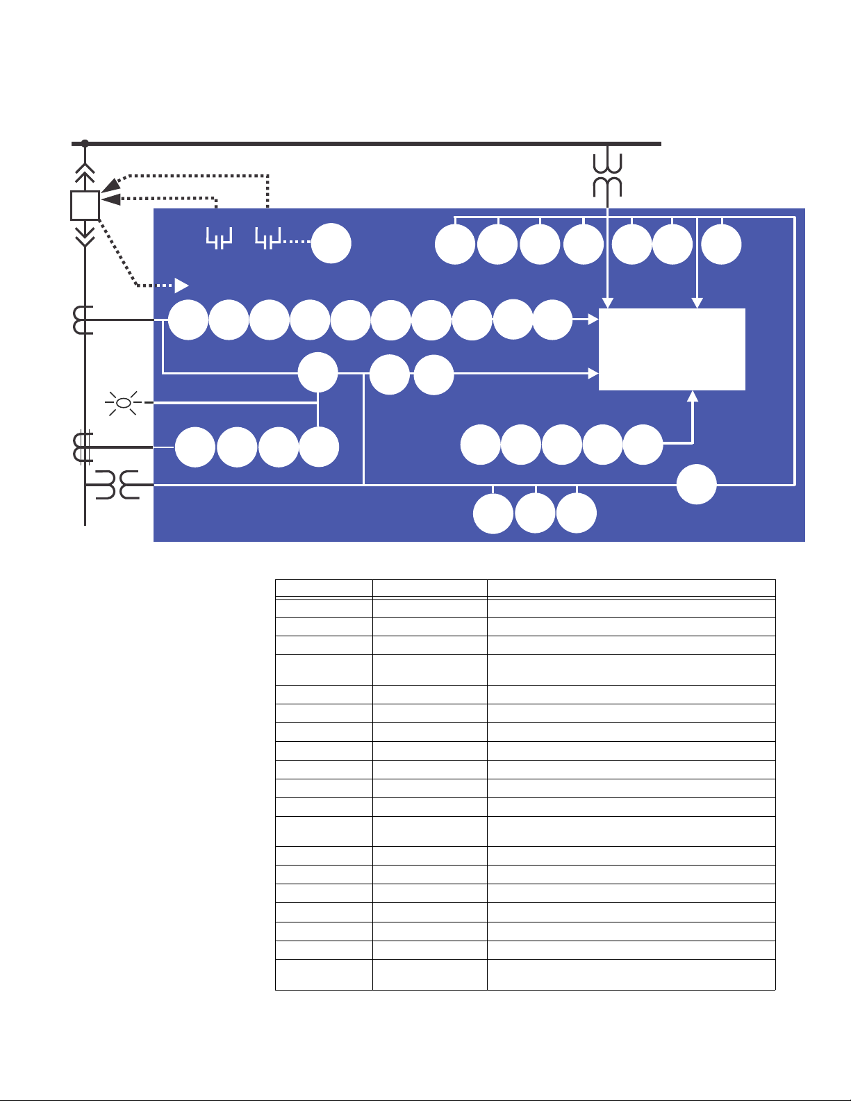
CHAPTER 1: INTRODUCTION DESCRIPTION OF THE 350 FEEDER PROTECTION SYSTEM
898742A7.CDR
A350 RELAYY
TRIP
BUS
LOAD
3
1
52
CLOSE
50G/
51G
50P 50N
79
22
21
METERING
TRANSIENT RECORDER
EVENT RECORDER
FAULT REPORT
51N51P
50_2
111
49
1
27X
59P27P
59X
59_2 59N 81U 81O
CLP
50BF
1
11
1
1122
MONITORING
BUS VT
67P
1
1
51_2
67N
1
CTS
25
51G/SG 67G/SG50G/SG
I/I
12
27_1
1
86
VTFF
1
24
32N
2
32
50P HS
1
1
50G/SG
HS
AF
SENSORS
Figure 1-1: Functional block diagram
Table 1-1: ANSI device numbers and functions
ANSI Code 61850 Logical Node Description
24 PVPH Volts per Hertz
25 RSYN1 Synchrocheck
27_1 psseqPTUV1 Positive Sequence Undervoltage
27P phsPTUV1, phsPTUV2,
27X auxPTUV1 Auxiliary Undervoltage
32 PDOP1, PDOP2 Directional Power
32N ndPDOP Wattmetric Ground Fault
I1/I2 (46BC) - Broken Conductor
49 PTTR1 Thermal Overload
50_2 ngseqPIOC1 Negative Sequence Overcurrent
350 FEEDER PROTECTION SYSTEM – INSTRUCTION MANUAL 1–3
50BF RBRF1 Breaker Failure
50G/SG gndPIOC1, gndPIOC2/
50N ndPIOC1, ndPIOC2 Neutral Instantaneous Overcurrent
50P phsPIOC1, phsPIOC2 Phase Instantaneous Overcurrent
51_2 ngseqPTOC1 Negative Sequence Time Overcurrent
51G/SG gndPTOC1/hsePTOC1 Ground/Sensitive Ground Time Overcurrent
51N ndPTOC1 Neutral Time Overcurrent
51P phsPTOC1 Phase Time Overcurrent
59_2 ngseqPTOV1,
phsPTUV3, phsPTUV4
hsePIOC1, hsePIOC2
ngseqPTOV2
Phase Undervoltage
Ground/Sensitive Ground Instantaneous Overcurrent
Negative Sequence Overvoltage
Page 14

DESCRIPTION OF THE 350 FEEDER PROTECTION SYSTEM CHAPTER 1: INTRODUCTION
ANSI Code 61850 Logical Node Description
59N ndPTOV1, nfPTOV2,
ndPTOV3, ndPTOV4
59P phsPTOV1, phsPTOV2,
phsPTOV3, phsPTOV4
59X auxPTOV1 Auxiliary Overvoltage
60CTS - CT Supervision
67G/SG gndRDIR1/hseRDIR1 Ground/Sensitive Ground Directional Element
67N ndRDIR1 Neutral Directional Element
67P phsRDIR1 Phase Directional Element
79 RREC1 Autoreclose
81O PTOF1, PTOF2, PTOF3,
PTOF4
81U PTUF2, PTUF2, PTUF3,
PTUF4
86 - Lockout
CLP - Cold Load Pickup
VTFF (60VTS) - Voltage Fuse Failure
- MMXU1 Voltage, Energy, Power Metering
Neutral Overvoltage
Phase Overvoltage
Overfrequency
Underfrequency
Table 1-2: Other device functions
Description
2nd Harmonic Blocking
Arc Flash Detector
Ambient Temperature
Breaker Control
Breaker Health
Breaker Maintenance
CT Failure Detection
Data Logger
Demand (in metering)
Digital Counters
DNP 3.0 Communications
Event Recorder
Fault Report
Flexcurves
HSR Communications
IEC 60870-5-103 Communications
IEC 60870-5-104 Communications
IEC 61850 Communications
IEC 61850 GOOSE Communications
Lockout (86)
Logic Elements
Metering: current, voltage, power, PF, energy, frequency, 2nd harmonics
Modbus User Map
Modbus RTU Communications
Modbus TCP Communications
Non-volatile Latches
OPC-UA Communications
1–4 350 FEEDER PROTECTION SYSTEM – INSTRUCTION MANUAL
Page 15

CHAPTER 1: INTRODUCTION 350 ORDER CODES
ACTUAL VALUES
COMMANDS
SETPOINTS
MAINTENANCE
ACTUAL VALUES
A1 STATUS
A2 METERING
A3 RECORDS
A4 TARGET MESSAGES
QUICK SETUP
RELAY STATUS
NOMINAL FREQUENCY
PH CT PRIMARY
PH CT SECONDARY
VT SEC. VOLTAGE
VT RATIO
AUX VT SECONDARY
AUX VT RATIO
PH TOC FUNCTION
NTRL TOC FNCTN
PH IOC1 FUNCTION
NTRL IOC1 FNCTN
▼
SETPOINTS
S1 RELAY SETUP
S2 SYSTEM SETUP
S3 PROTECTION
S4 CONTROLS
S5 INPUTS/OUTPUTS
▼
MAINTENANCE
M1 RELAY INFO
M3 BKR MAINTENANCE
M5 RELAY MAINT
M6 FACTORY SERVICE
M4 BKR MONITOR
▼
898756A3.cdr
[S]GND CT SECONDARY
S6 MONITORING
M7 TESTING
QUICK SETUP
[S]GND CT PRIMARY
VT CONNECTION
[S]GND TOC FUNCTION
[S]GND IOC1 FNCTN
Description
Output Relays
PRP Communications
Relay Maintenance
Remote Inputs (32)
Setpoint Groups (2)
Test Mode
Transient Recorder (Oscillography)
Trip and Close Coil Monitoring
User Curves
User-programmable LEDs
Virtual Inputs (32)
Virtual Outputs (32)
Figure 1-2: Main Menu structure
350 order codes
350 FEEDER PROTECTION SYSTEM – INSTRUCTION MANUAL 1–5
The information to specify a 350 relay is provided in the following order code figure.
Page 16

350 ORDER CODES CHAPTER 1: INTRODUCTION
350 * * * * * * * * * * * *
Interface 350 ||||||||||| | 350 Feeder Protection System
User Interface E | | | | | | | | | | | English without programmable LEDs
L | | | | | | | | | | | English with programmable LEDs
Phase Currents
a
a. Phase Current options PX/P0 and Ground Current options GX/G0 are only available with the non-drawout Case Design N.
PX|||||||||| No CT
P0||||||||| | 1 A or 5 A configurable phase current inputs
P1||||||||| | 1 A 3-phase current inputs
P5||||||||| | 5 A 3-phase current inputs
Ground Currents
b
b. Ground Currents G1/G5 and S1/S5 must match the corresponding P1/P5 Phase Currents (i.e. 5A and 1A must not be mixed).
Ground Current GX requires PX Phase Current, and is only available with Case N, Current Protection N, Other Options V, and Input/Output E.
Ground Current G0/S0 must match the P0 Phase Current, and is only available with the non-drawout Case Design N.
GX | | | | | | | | | No CT
G0 | | | | | | | | | 1 A and 5 A configurable ground current input
G1 | | | | | | | | | 1 A ground current input
G5 | | | | | | | | | 5 A ground current input
S0 | | | | | | | | | 1 A or 5A configurable sensitive ground current input
S1 | | | | | | | | | 1 A sensitive ground current input
S5 | | | | | | | | | 5 A sensitive ground current input
Power Supply L | | | | | | | | 24 to 48 V DC
H|||||||| 125 to 250 V DC/120 to 230 V AC
Input/Output
c
c. Input/Output option A is only available with the non-drawout Case Design N
E | | | | | | | Standard (10 Inputs, 7 relay outputs)
A | | | | | | | Standard (10 inputs, 5 relay outputs, 2 MOSFET loads) + 4 Arc Flash detectors
Current Protection
d
d. Current Protection option S has been discontinued.
N|||||| None (voltage and frequency relay, requires a PX/GX configuration)
E
||||||||||||Extended configuration: User selectable 49, 50P(2), 50G/SG(2), 50N(2), 51P(1), 51G/SG(1),
51N(1)
M
||||||||||||Advanced configuration: Extended + 51_2 or 46(1), 50_2 (1) or 46(1),
I1/I2(46BC)
Control N | | | | | CLP, Lockout (86)
C | | | | | CLP, 50BF, Lockout (86), Autoreclose (79)
Other Options
e
e. CLP, 79, and 50BF are not supported when V is selected under Other Options.
N| | | | No selection
V
||||||||27P(4), 27X(1), 27P_1(1), 59P(4), 59N(4), 59X(1), 59_2(2), 81O(4), 81U(4), 25(1), VTFF(1), 24(1),
Voltage Metering (requires a PX/GX configuration)
D| | | | Neutral and Ground Directional Overcurrent Protection: 67N(1), 67G/SG(1), 60CTS
M| | | | Voltage, Power, and Energy Metering, 60CTS
R
||||||||Phase, Neutral, and Ground Directional Overcurrent Protection: 67P(1), 67N(1), 67G/
SG(1), 32N(2), VTFF + Voltage, Power, and Energy Metering, 60CTS
P||
|
|
|
|
|
|
|
|
|
|
Extended Protection: 27P(2), 27X(1), 27P_1 (1), 59P(2), 59N(1), 59X(1), 59_2(1), 81O(2),
81U(2), 67P(1), 67N(1), 67G/SG(1), VTFF(1), 25(1), 60CTS, Voltage, Power, and Energy
Metering
W| | | | Advanced Protection: Extended + 32(2)
Communications
f
f. Communications option 4E allows the selection of either IEC 61850 or OPC-UA; both cannot be used at the same time.
Communications option 5E is only available with Case Design D or X. 898800AA.PDF
S N | | Standard: Front USB, Rear RS485: Modbus RTU, DNP3.0, IEC60870-5-103
1 E
||||Standard + Ethernet (Copper & Fiber - MTRJ),
Modbus TCP/IP, DNP3.0, IEC 60870-5-104
2 E
||||Standard + Ethernet (Copper & Fiber - MTRJ),
Modbus TCP/IP, DNP3.0, IEC 60870-5-104, IEC 61850 GOOSE
3 E
||||Standard + Ethernet (Copper & Fiber - MTRJ),
Modbus TCP/IP, DNP3.0, IEC 60870-5-104, IEC 61850
4 E
||||Standard + Ethernet (Copper & Fiber - MTRJ),Modbus TCP/IP, DNP3.0, IEC 60870-5-104,
IEC 61850, OPC-UA
5 E
||||Standard + Ethernet (Dual Fiber - MTRJ),Modbus TCP/IP, DNP3.0, IEC 60870-5-104, IEC
61850, OPC-UA, PRP, HSR, 1588, PTP
Case Design D | Protection Relay with drawout design
N| Protection Relay with non-drawout design
X| Protection Relay (drawout design) with no chassis
Harsh Environment N None
H Harsh Environment Conformal Coating
Figure 1-3: Order Codes
1–6 350 FEEDER PROTECTION SYSTEM – INSTRUCTION MANUAL
Page 17

CHAPTER 1: INTRODUCTION 350 ORDER CODES
NOTE
897800AF-A1.fm
AFC * *
AF System Component E | Sensor Fiber Extension (black sensor fiber with two single
bulkhead connectors, used with loop sensors)
L | Loop Sensor with transparent sensor fiber
P | Point Sensor with black sensor fiber
Sensor Fiber Length XX Sensor fiber length:
01 to 35 meters for Point Sensors and Extensions
01 to 70 meters for Loop Sensors
NOTE:
FASTPATH:
FASTPATH:
Features related to each order number are subject to change without notice.
Arc Flash System
The 350 protection relay with Input/Output option “A” supports up to 4 Arc Flash sensors,
which are ordered separately so that the connected sensor fiber lengths can be
customized.
The total sensor fiber length connected to each loop sensor must not exceed 70 meters of
single sensor fiber. Black sensor fiber is duplex, and must be doubled in calculations.
For example, a loop sensor with a 25 meter transparent sensor fiber plus a sensor fiber
extension of 10 meters would have a total of 2 x 10m + 25m = 45m of single sensor fiber.
The total sensor fiber length connected to each point sensor must not exceed 35 meters of
black (duplex) cable.
NOTE:
NOTE:
FASTPATH:
Generally each loop sensor is used with a sensor fiber extension, in order to minimize
exposure to ambient light when running the sensor fiber between cabinets. A duplex
sensor fiber extension connects the relay to the loop sensor, and can be gently pulled
apart to connect to the loop sensor connectors if they are not adjacent. Consider your
installation needs carefully when ordering sensor and extension lengths.
Empty chassis
The 350 protection relay chassis used with a drawout relay is available separately, for use
as a partial replacement or in test environments. Many features are supported by the
cards and ports within the chassis, as is reflected in the chassis order code.
The chassis order code and drawout relay order code must match exactly.
A drawout relay cannot be used in a chassis with different order code options.
350 FEEDER PROTECTION SYSTEM – INSTRUCTION MANUAL 1–7
Page 18

350 ORDER CODES CHAPTER 1: INTRODUCTION
NOTE
350 CH * * * * * *
Phase Currents P1 | | | | | 1 A 3-phase current inputs
P5 | | | | | 5 A 3-phase current inputs
Ground Currents
a
a. Ground current options G1/G5 must match the corresponding P1/P5 Phase currents
G1 | | | | 1 A ground current input
G5 | | | | 5 A ground current input
S1 | | | | 1 A sensitive ground current input
S5 | | | | 5 A sensitive ground current input
Other Options N | | | No selection
D| | | Neutral and Ground Directional Overcurrent Protection: 67N(1), 67G/SG(1), 60CTS
M| | | Voltage, Power, and Energy Metering, 60CTS
R
||||||Phase, Neutral, and Ground Directional Overcurrent Protection: 67P(1), 67N(1),
67G/SG(1), 32N(2), VTFF + Voltage, Power, and Energy Metering, 60CTS
P
|||||
|
Extended Protection: 27P(2), 27X(1), 27P_1 (1), 59P(2), 59N(1), 59X(1), 59_2(1), 81O(2),
81U(2), 67P(1), 67N(1), 67G/SG(1), VTFF(1), 25(1), 60CTS, Voltage, Power, and Energy
Metering
W| | | Advanced Protection: Extended + 32(2)
Communications
b
b. Communications option 4E allows the selection of either IEC 61850 or OPC-UA; both cannot be used at the same time.
898800CH-A2.PDF
S N | Standard: Front USB, Rear RS485: Modbus RTU, DNP3.0, IEC60870-5-103
1 E
||Standard + Ethernet (Copper & Fiber - MTRJ),
Modbus TCP/IP, DNP3.0, IEC 60870-5-104
2 E
||Standard + Ethernet (Copper & Fiber - MTRJ),
Modbus TCP/IP, DNP3.0, IEC 60870-5-104, IEC 61850 GOOSE
3 E
||Standard + Ethernet (Copper & Fiber - MTRJ),
Modbus TCP/IP, DNP3.0, IEC 60870-5-104, IEC 61850
4 E
||Standard + Ethernet (Copper & Fiber - MTRJ),Modbus TCP/IP, DNP3.0, IEC 60870-5-
104, IEC 61850, OPC-UA
5 E
||Standard + Ethernet (Dual Fiber - MTRJ),Modbus TCP/IP, DNP3.0, IEC 60870-5-104,
IEC 61850, OPC-UA, PRP, HSR, 1588, PTP
Harsh Environment N None
H Harsh Environment Conformal Coating
Figure 1-4: 350 chassis order codes
NOTE:
1–8 350 FEEDER PROTECTION SYSTEM – INSTRUCTION MANUAL
Other accessories
• 1819-0103 350 Retrofit Kit for 735
• 1819-0102 350 Retrofit Kit for IAC Relay
• 1819-0101 350 Retrofit Kit for MDP Relay
• 1819-0100 350 Retrofit Kit for S1/S2 Cut-Out
• 18L0-0075 3 Series Depth reducing collar - 1.375”
• 18L0-0076 3 Series Depth reducing collar - 3.00”
• 18L0-0080 3 Series IP20 Kit
• 3S-NDO-STCONKIT 3 Series NDO straight terminal block kit
• 0804-0458 USB A-B configuration cable - 6’
Refer to the 3 Series Retrofit Instruction Manual for the retrofit of Multilin MI, MII, MLJ, and
TOV relays.
Page 19

CHAPTER 1: INTRODUCTION SPECIFICATIONS
NOTE
NOTE
Specifications
NOTE:
NOTE:
Specifications are subject to change without notice.
To obtain the total element operating time, i.e. from the presence of a trip condition to
initiation of a trip, add 8 ms output relay time to the operate times listed below, with the
exception of Arc Flash SSR loads.
Password security
PASSWORD SECURITY
Master Password: ...............................................8 to 10 alpha-numeric characters
Settings Password:.............................................3 to 10 alpha-numeric characters for local and remote
access
Control Password:...............................................3 to 10 alpha-numeric characters for local and remote
access
Protection
BROKEN CONDUCTOR (I1/I2 OR 46BC)
Minimum operating positive current:........ 0.05 to 1.00 x CT in steps of 0.01 x CT
Maximum operating positive current:....... 0.05 to 5.00 x CT in steps of 0.01 x CT
Pickup level:........................................................... 20.0% to 100.0% in steps of 0.1%
Dropout level:........................................................ 97% to 98% of the pickup level
Pickup time delay: .............................................. 0.000 to 65.535 s in steps of 0.001 s
Timer accuracy: .................................................. ± 3% of delay setting or ± ¾ cycle (whichever is greater)
from pickup to operate
Operate time:........................................................ <30 ms at 60 Hz
WATTMETRIC GROUND FAULT (32N)
Measured power:................................................ zero sequence
Number of elements: ........................................ 1
Characteristic angle: ......................................... 0º to 359º in steps of 1°
Pickup threshold:................................................. 0.001 to 1.200 pu in steps of 0.001 pu
Pickup level accuracy:...................................... ± 2% or ± 0.03 pu, whichever is greater
Hysteresis:.............................................................. 3% or 0.001 pu, whichever is greater
Pickup delay:......................................................... Definite T ime (0.00 to 600 .0 s in steps of 0.1 s), Inverse T ime,
or Flexcurve
Inverse time multiplier:..................................... 0.01 to 2.00 in steps of 0.01
Curve timing accuracy:.................................... ± 3.5% of operate time or ± ¼ cycle (whichever is greater)
from pickup to operate
Operate time:........................................................ <30 ms at 60 Hz
350 FEEDER PROTECTION SYSTEM – INSTRUCTION MANUAL 1–9
Page 20

SPECIFICATIONS CHAPTER 1: INTRODUCTION
DIRECTIONAL POWER (32)
Measured power:................................................ 3-phase
Characteristic angle:......................................... 0º to 359º in steps of 1°
Power pickup range: ......................................... -1.200 to 1.200 x Rated Power in steps of 0.001
Pickup level accuracy:...................................... 2.5% or 0.01 pu, whichever is greater
Hysteresis: ............................................................. 2% or 0.001 x Rated Power, whichever is greater
Pickup time delay:.............................................. 0.0 to 600.0 s in steps of 0.1 s
Operate time:........................................................ < 55 ms at 1.1 x pickup at 60 Hz
< 65 ms at 1.1 x pickup at 50 Hz
Timer accuracy:.................................................. ± 3% of delay setting or ± ¼ cycle (whichever is greater)
from pickup to operate
VOLTS PER HERTZ (24)
Inputs: ...................................................................... Van (Wye VTs), Vab (Delta VTs)
Pickup Level: ......................................................... 0.80 to 4.00 x V/Hz in steps of 0.01 x V/Hz
Dropout Level:...................................................... 97% to 98% of pickup
Level Accuracy: ................................................... ± 0.02 x V/Hz or 2% of set value, whichever is greater
Time Curves:......................................................... Definite Time, Inverse A/B/C, FlexCurves A/B
TD Multiplier: ......................................................... 0.00 to 600.00 s in steps of 0.01 s
Reset Delay: .......................................................... 0.00 to 600.00 s in steps of 0.01 s
Time Accuracy:.................................................... ± 3% of operate time of ±15 cycles (whichever is greater) for
values greater than 1.1 x pickup
PHASE/NEUTRAL/GROUND/NEGATIVE SEQUENCE TIME OVERCURRENT (51P/51N/51G/
51_2)
Pickup Level: ......................................................... 0.05 to 20.00 x CT in steps of 0.01 x CT
Dropout Level:...................................................... 97% of Pickup @ I > 1 x CT
Pickup - 0.02 x CT @ I < 1 x CT
Curve Shape:......................................................... ANSI Extremely/Very/Moderately/Normally Inverse
Definite T ime (0.1 s base curve)
IEC Curve A/B/C and Short Inverse
IAC Extreme/Very/-/Short Inverse
User Curve, FlexCurve™ A/B (programmable curves)
Curve Multiplier: .................................................. 0.05 to 50.00 in steps of 0.01
Reset Time: ............................................................ Instantaneous, Linear
Curve Timing Accuracy:.................................. ±3% of expected inverse time or 1.5 cycle, whichever is
greater, from pickup to operate
Level Accuracy: ................................................... per CT input
SENSITIVE GROUND TIME OVERCURRENT (51SG)
Pickup Level: ......................................................... 0.005 to 3.000 x CT in steps of 0.001 x CT
Dropout Level:...................................................... 97% of Pickup @ I > 0.1 x CT
Pickup - 0.002 x CT @ I < 0.1 x CT
Curve Shape:......................................................... ANSI Extremely/Very/Moderately/Normally Inverse
Definite T ime (0.1 s base curve)
IEC Curve A/B/C/Short Inverse
IAC Extreme/Very/-/Short Inverse
User Curve, FlexCurve™ A/B
Curve Multiplier: .................................................. 0.05 to 50.00 in steps of 0.01
Reset Time: ............................................................ Instantaneous, Linear
Curve Timing Accuracy:.................................. ±3% of expected inverse time or 1 cycle, whichever is
greater, from pickup to operate
Level Accuracy: ................................................... per CT input
1–10 350 FEEDER PROTECTION SYSTEM – INSTRUCTION MANUAL
Page 21

CHAPTER 1: INTRODUCTION SPECIFICATIONS
PHASE/NEUTRAL/GROUND/NEGATIVE SEQUENCE INSTANTANEOUS OVERCURRENT
(50P/50N/50G/50_2)
Pickup Level:.......................................................... 0.05 to 20.00 x CT in steps of 0.01 x CT
Dropout Level: ...................................................... 97% of Pickup @ I > 1 x CT
Pickup - 0.02 x CT @ I <1 x CT
Time Delay:............................................................ 0.00 to 300.00 sec in steps of 0.01
Operate Time:....................................................... <30 ms @ 60Hz (I > 2.0 x PKP, No time delay)
<35 ms @ 50Hz (I > 2.0 x PKP, No time delay)
Time Delay Accuracy: ...................................... 1% or 1 cycle, whichever is greater (Time Delay selected)
Level Accuracy:.................................................... per CT input
SENSITIVE GROUND INSTANTANEOUS OVERCURRENT (50SG)
Pickup Level (Gnd IOC):..................................... 0.005 to 3.000 x CT in steps of 0.001 x CT
Dropout Level: ...................................................... 97% of Pickup @ I > 0.1 x CT
Pickup - 0.002 x CT @ I < 0.1 x CT
Time Delay:............................................................ 0.00 to 300.00 sec in steps of 0.01
Operate Time:....................................................... <30 ms @ 60Hz (I > 2.0 x PKP, No time delay)
<35 ms @ 50Hz (I > 2.0 x PKP, No time delay)
Time Delay Accuracy: ...................................... 1% or 1 cycle, whichever is greater (Time Delay selected)
Level Accuracy:.................................................... per CT input
PHASE DIRECTIONAL (67P)
Directionality: ....................................................... Co-existing forward and reverse
Operating:............................................................... Phase Current (Ia, Ib, Ic)
Polarizing Voltage:.............................................. Quadrature Voltage
(ABC phase sequence: Vbc, Vca, Vab)
(CBA phase sequence: Vcb, Vac, Vba)
Polarizing voltage threshold:......................... 0.05 to 1.25 x VT in steps of 0.01
MTA (Maximum Torque Angle): ..................... From 0º to 359º in steps of 1°
Angle Accuracy: .................................................. ±4º
Operational Delay: ............................................. 20 to 30 ms
NOTE:
The selection of the “P” or “R” option from “350 OTHER OPTIONS” in the order code table,
will enable the Phase directional element. The polarizing voltage used for this element is
the line voltage.
GROUND DIRECTIONAL (67G)
Directionality: ....................................................... Co-existing forward and reverse
Operating:............................................................... Ground Current (Ig)
Polarizing Voltage:.............................................. -V
calculated using phase voltages (VTs must be connected
0
in “Wye”)
-3V
measured from Vaux input. (3V0 provided by an
0
external open delta connection).
MTA (Maximum Torque Angle): ..................... From 0º to 359º in steps of 1°
Angle Accuracy: .................................................. ±4º
Operational Delay: ............................................. 20 to 30 ms
NOTE:
The selection of the “D” option from “350 OTHER OPTIONS” in the Order Code table, will
enable the Ground Directional element with voltage polarizing 3V
measured from the
0
Vaux voltage input.
NOTE:
The selection of the “P”, “R”, or “W” option from “350 OTHER OPTIONS” in the order code
table, will enable the Ground directional element. The polarizing voltage used for this
element is the computed V0 from the measured phase voltage inputs.
350 FEEDER PROTECTION SYSTEM – INSTRUCTION MANUAL 1–11
Page 22

SPECIFICATIONS CHAPTER 1: INTRODUCTION
NOTE
NEUTRAL DIRECTIONAL (67N)
Directionality: ....................................................... Forward and reverse
Polarizing:............................................................... Voltage, Current, Dual
Polarizing Voltage:.............................................. - V
Polarizing Current:.............................................. I
MTA:........................................................................... From 0º to 359º in steps of 1°
Angle Accuracy: .................................................. ±4º
Operational Delay:............................................. 20 to 30 ms
NOTE:
The selection of the “D” option from “350 OTHER OPTIONS” in the Order Code table, will
enable the Neutral Directional element with voltage polarizing 3V
calculated using phase voltages (VTs must be
0
connected in “Wye”)
-3V
measured from Vaux input (3V0 provided by an
0
external broken delta connection).
G
measured from the
0
Vaux voltage input.
The selection of “P”, “R”, or “W” option from “350 OTHER OPTIONS” in the Order Code table,
will enable the Neutral Directional elements with voltage polarizing V
computed from the
0
measured phase voltage inputs.
The ground polarizing current, IG, is available for selection in both cases.
THERMAL OVERLOAD (49)
Current:.................................................................... RMS current - max (Ia, Ib, Ic)
Pickup Accuracy: ................................................ per current inputs
Timing Accuracy:................................................ See graph below
Figure 1-5:
The graph shows the trip time error with respect to the ratio of cable load and thermal
model pickup setting. With a smaller I/Ipkp ratio, the time error tends to be higher, as
accumulated through the logarithmic formula, the measurement error, and the time of
measurement. For higher I/Ipkp ratios, the time to trip is substantially more accurate. Each
point on the graph represents a trip time error, with the I/Ipkp ratio kept constant during
the test.
PHASE/AUXILIARY/POSITIVE SEQUENCE UNDERVOLTAGE (27P, 27X, 27_1)
Minimum Voltage: .............................................. Programmable from 0.00 to 1.25 x VT in steps of 0.01
Pickup Level: ......................................................... 0.00 to 1.25 x VT in steps of 0.01
Dropout Level:...................................................... 102% of pickup (pickup > 0.1 x VT)
Pickup + 0.02 x VT (pickup < 0.1 x VT)
Curve: ....................................................................... Definite Time, Inverse Time
Time Delay: ........................................................... 0.00 to 600.00 s in steps of 0.01
Operate Time: ...................................................... T ime delay ±30 ms @ 60 Hz (V < 0.85 x PKP)
Time delay ±40 ms @ 50 Hz (V < 0.85 x PKP)
Time Delay Accuracy:...................................... ±3% of expected time, or 1 cycle, whichever is greater
Level Accuracy: ................................................... Per voltage input
1–12 350 FEEDER PROTECTION SYSTEM – INSTRUCTION MANUAL
Page 23

CHAPTER 1: INTRODUCTION SPECIFICATIONS
NOTE
PHASE/AUXILIARY/NEUTRAL/NEGATIVE SEQUENCE OVERVOLTAGE (59P, 59X, 59N, 59_2)
Pickup Level:.......................................................... 0.00 to 1.25 x VT in steps of 0.01
Dropout Level: ...................................................... 98% of pickup (pickup > 0.1 x VT)
Pickup - 0.02 x VT (pickup < 0.1 x VT)
Time Delay:............................................................ 0.00 to 600.00 s in steps of 0.01
Operate Time:....................................................... Time delay ±35 ms @ 60Hz (V > 1.1 x PKP)
Time delay ±40 ms @ 50Hz (V > 1.1 x PKP)
Time Delay Accuracy: ...................................... ±3% of expected time, or 1 cycle, whichever is greater
Level Accuracy:.................................................... Per voltage input
UNDERFREQUENCY (81U)
Minimum Voltage:............................................... 0.00 to 1.25 x VT in steps of 0.01
Pickup Level:.......................................................... 40.00 to 70.00 Hz in steps of 0.01
Dropout Level: ...................................................... Pickup + 0.05 Hz
Time Delay:............................................................ 0.10 to 600.0 s in steps of 0.01
Time Delay Accuracy: ...................................... 0 to 6 cycles (Time Delay selected)
Operate Time:....................................................... Typically 10 cycles @ 0.1Hz/s change
Level Accuracy:.................................................... ±0.03 Hz
OVERFREQUENCY (81O)
Minimum Voltage:............................................... 0.3 x VT
Pickup Level:.......................................................... 40.00 to 70.00 Hz in steps of 0.01
Dropout Level: ...................................................... Pickup - 0.05 Hz
Time Delay:............................................................ 0.1 to 600.0 s in steps of 0.01
Time Delay Accuracy: ...................................... 0 to 6 cycles (Time Delay selected)
Operate Time:....................................................... Typically 10 cycles @ 0.1Hz/s change
Level Accuracy:.................................................... ±0.03 Hz
ARC FLASH HS PHASE/GROUND INSTANTANEOUS OVERCURRENT HS 50P/50G
Current:.................................................................... RMS Magnitude (special high speed algorithm)
Pickup Level:.......................................................... 0.050 to 30.000 x CT in steps of 0.001 x CT
Dropout Level: ...................................................... 97 to 98% of Pickup
Level Accuracy:.................................................... For 0.1 to 0.2 x CT: ± 0.2% of reading or 1.5% of rated
current, whichever is greater
For > 0.2 x CT: ± 5% of reading
Operate Time:....................................................... 4 ms at >6 x Pickup at 60 Hz
5 ms at >6 x Pickup at 50 Hz
4-8 ms at > (3-6) x Pickup at 60 Hz
4-10 ms at > (3-6) x Pickup at 50 Hz
NOTE:
The operate times listed require that SSR output relays (Aux 5 and 6) be used for Arc Flash
detection.
ARC FLASH SENSOR/FIBER
Number of Sensors: ........................................... 4
Detection Radius:................................................ 180 degree
Maximum Duplex Fiber Length (Point
Sensor):............................................................... 35 m
Maximum Single Fiber Length (Loop
Sensor):............................................................... 70 m
Fiber Size:................................................................ 1.0 mm core diameter
2.2 mm total diameter (single)
4.4 mm total diameter (duplex)
Mode:........................................................................ Multi-mode
Connector:.............................................................. Small Media Interface (SMI)
Fiber Type:.............................................................. Plastic Optical Fiber
Bend Radius: ......................................................... 35 mm minimum
Product Type:........................................................ Class 1 Laser product
350 FEEDER PROTECTION SYSTEM – INSTRUCTION MANUAL 1–13
Page 24

SPECIFICATIONS CHAPTER 1: INTRODUCTION
NOTE
Metering
PARA METER ACCURACY
3-Phase Real Power (MW or kW) ±1% of full scale 0.1 MW ± 100000.0 kW
3-Phase Reactive Power (Mvar or kvar) ±1% of full scale 0.1 Mvar ± 100000.0 kvar
3-Phase Apparent Power (MVA or kVA) ±1% of full scale 0.1 MVA ± 100000.0 kVA
3-Phase Positive Watthour (MWh) ±1% of full scale ±0.001 MWh 50000.0 MWh
3-Phase Negative Watthour (MWh) ±1% of full scale ±0.001 MWh 50000.0 MWh
3-Phase Positive Varhour (Mvarh) ±1% of full scale ±0.001 Mvarh 50000.0 Mvarh
3-Phase Negative Varhour (Mvarh) ±1% of full scale ±0.001 Mvarh 50000.0 Mvarh
Power Factor ±0.05 0.01 -0.99 to 1.00
Frequency ±0.05 Hz 0.01 Hz 40.00 to 70.00 Hz
NOTE:
Negative values (-) represent lead and positive values (+) represent lag.
(full scale for
CT Input is 3 x CT)
RESOLUTION RANGE
CURRENTS
Parameters:...........................................................Phase A, Phase B, Phase C, Neutral, Ground, Sensitive
Ground, Positive Sequence, Negative Sequence, Zero
Sequence, and 2nd Harmonic
Accuracy: ...............................................................See the Inputs section in Chapter 1: Specifications
VOLTAGES
Parameters:...........................................................Wye VTs: AN, BN, CN, Negative Sequence, Zero Sequence
and Auxiliary
Delta VTs: AB, BC, CA, Negative Sequence, Zero Sequence
and Auxiliary
Accuracy: ...............................................................See the Inputs section in Chapter 1: Specifications
Data capture
TRANSIENT RECORDER
Buffer size: .............................................................3 s
No. of buffers:.......................................................1, 3, 6
No. of channels:................................................... 14
Sampling rate:......................................................4, 8, 16, or 32 samples per cycle
Triggers: ..................................................................Manual Command
Data: .........................................................................AC input channels
Data storage:........................................................ RAM - battery backed-up
FAULT RECORDER
Number of records:............................................ 1
Content:................................................................... Date and Time, first cause of fault, phases,
Contact Input
Virtual Input
Logic Element
Element Pickup/Trip/Dropout/Alarm
Contact input state
Contact output state
Virtual input state
Logic element state
Currents: Ia, Ib, Ib, Ig/Isg, In - magnitudes and angles
Voltages: Van, Vbn, Vcn, Vab, Vbc, Vca, Vaux - magnitudes
and angles
System frequency
1–14 350 FEEDER PROTECTION SYSTEM – INSTRUCTION MANUAL
Page 25

CHAPTER 1: INTRODUCTION SPECIFICATIONS
EVENT RECORDER
Number of events:..............................................256
Header: ....................................................................relay name, order code, firmware revision
Content:...................................................................event number, date of event, cause of event,per-phase
current, ground current, sensitive ground current, neutral
current, per-phase voltage (VTs connected in “Wye”), or
phase-phase voltages (VTs connected in “Delta”), system
frequency, power, power factor, thermal capacity
Data Storage:........................................................Retained for 3 days
CLOCK
Setup:........................................................................Date and time
Daylight Saving Time
IRIG-B:.......................................................................Auto-detect (DC shift or Amplitude Modulated)
Amplitude modulated: 1 to 10 V pk-pk
DC shift: 1 to 10 V DC
Input impedance: 40 kOhm ± 10%
Accuracy with IRIG-B:....................................... ± 1 ms
Accuracy without IRIG-B:................................± 1 min / month
Control
LOGIC ELEMENTS
Number of logic elements: .............................16
Trigger source inputs per element: ............2 to 8
Block inputs per element: ...............................2 to 4
Supported operations: .....................................AND, OR, NOR, NAND, XOR, XNOR, Pickup / Dropout timers
Pickup timer:..........................................................0 to 60000 ms in steps of 1 ms
Dropout timer:......................................................0 to 60000 ms in steps of 1 ms
BREAKER CONTROL
Operation:...............................................................Asserted Contact Input, Logic Element, Virtual Input, Manual
Command
Function: .................................................................Opens / closes the feeder breaker
AUTORECLOSE (79)
Reclose attempts:...............................................Up to 4 shots
Time Delay Accuracy: ......................................0 to 3 cycles (AR Dead Time selected)
Elements: ................................................................Inputs, Outputs, Breaker Status (52 status)
SYNCHROCHECK (25)
Maximum frequency difference:.................0.05 to 5.00 Hz in steps of 0.01 Hz
Maximum Angle difference:...........................2° to 80° in steps of 1°
Maximum Voltage difference:.......................10 to 10000 V in steps of 1 V
Dead Bus and Dead Line level:.....................0.00 to 1.25 x VT in steps of 0.01 x VT
Live Bus and Live Line level:...........................0.03 to 1.25 x VT in steps of 0.01 x VT
SECOND HARMONIC INHIBIT
Operating Parameter:.......................................Current 2nd harmonic per phase or average
Pickup Level:..........................................................0.1% to 40.0% in steps of 0.1
Minimum Current:...............................................0.03 to 3.00 x CT in steps of 0.01 x CT
Time Delay:............................................................0.00 to 600.00 s in steps of 0.01 s
Time Delay Accuracy: ......................................±3% of expected time or 2 cycles, whichever is greater
Level Accuracy:....................................................±2% or ±10mA (whichever is greater)
350 FEEDER PROTECTION SYSTEM – INSTRUCTION MANUAL 1–15
Page 26

SPECIFICATIONS CHAPTER 1: INTRODUCTION
BREAKER FAILURE (50BF)
Pickup Level: .........................................................0.05 to 20.00 x CT in steps of 0.01 x CT
Dropout Level:......................................................97 to 98% of pickup
Timer 1 Delay: ...................................................... 0.03 to 1.00 s in steps of 0.01 s
Timer 2 Delay: ...................................................... 0.00 to 1.00 s in steps of 0.01 s
Time Delay Accuracy:...................................... 0 to 1 cycle (T imer 1, T imer 2)
Level Accuracy: ...................................................per CT input
Reset Time: ............................................................<14 ms typical at 2 x pickup at 60 Hz
<16 ms typical at 2 x pickup at 50 Hz
CT FAILURE
Inputs: ......................................................................Neutral Current IN,
Neutral Current VN (from three-phase VTs)
Ground Current Ig
Time Delay: ........................................................... 0.00 to 60.00 s in steps of 0.01 s
3IO level accuracy: ............................................per CT inputs
3VO level accuracy:........................................... per VT inputs
GND current level accuracy:.........................see the specifications for phase and ground current inputs
Operate Time: ......................................................30 ms at 60 Hz
35 ms at 50 Hz
BREAKER TRIP COUNTER
Trip Counter Limit (Pickup):............................. 1 to 10000 in steps of 1
LOCKOUT
Function:................................................................. Latch Trip command to Relay 1 TRIP
Block Close to Relay 2 CLOSE
Operation: ..............................................................Any protection element
COLD LOAD PICKUP BLOCKING
Operation: ..............................................................Automatically (current level), or by command (asserted
input)
Function:................................................................. Block IOC functions, raise TOC pickup, for selected period of
time
Time Delay Accuracy:...................................... 0 to 1 cycle (block Time)
±50 ms (outage time ≤5 min)
±1 s (outage time > 5 min)
FUSE FAIL (VTFF)
Time Delay: ........................................................... 1 s
Timing Accuracy:................................................ ±0.5 s
Elements:................................................................ Trip or Alarm
AMBIENT TEMPERATURE
High Temperature Pickup:.............................. 20°C to 80°C in steps of 1°C
Low Temperature Pickup:...............................-40°C to 20°C in steps of 1°C
Time Delay: ........................................................... 1 to 60 min in steps of 1 min
Temperature Dropout:......................................Configurable 90 to 98% of pickup
Temperature Accuracy:................................... ±10°C
Timing Accuracy:................................................ ±1 second
1–16 350 FEEDER PROTECTION SYSTEM – INSTRUCTION MANUAL
Page 27

CHAPTER 1: INTRODUCTION SPECIFICATIONS
Monitoring
BREAKER HEALTH
Timer Accuracy: ..................................................± 3% of delay setting or ± 1 cycle (whichever is greater) from
pickup to operate
DEMAND
Measured Values:................................................Phase A/B/C present and maximum current, three-phase
present and maximum real/reactive/apparent power
Measurement Type:...........................................Thermal Exponential, 90% response time (programmed): 5,
10, 15, 20, 30 minutes
Block Interval / Rolling Demand, time interval (programmed):
5, 10, 15, 20, 30 minutes
Current Pickup Level:.........................................10 to 10000 in steps of 1 A
Real Power Pickup Level:.................................0.1 to 300000.0 in steps of 0.1 kW
Reactive Power Pickup Level:........................0.1 to 300000.0 in steps of 0.1 kVar
Apparent Power Pickup Level: ......................0.1 to 300000.0 in steps of 0.1 kVA
Dropout Level: ......................................................96-98% of Pickup level
Level Accuracy:....................................................± 2% (current demand only)
Inputs
CONTACT INPUTS
Inputs:.......................................................................10
Selectable thresholds:.......................................17, 33, 84, 166 VDC
±10%
Recognition time:................................................1/2 cycle
Debounce time: ...................................................1 to 64 ms, selectable, in steps of 1 ms
Maximum input voltage & continuous
current draw:...................................................300 VDC, 2 mA, connected to Class 2 source
Type: .........................................................................opto-isolated inputs
External switch: ...................................................wet contact
PHASE & GROUND CURRENT INPUTS
CT Primary: ............................................................1 to 6000 A
Range: ......................................................................0.02 to 20 × CT
Input type:..............................................................1 A, 5 A, or 1/5 A (must be specified with order)
Nominal frequency:...........................................50/60 Hz
Burden: ....................................................................<0.1 VA at rated load
Accuracy:................................................................3%
±10 mA or ±20% of reading from 0.02 to 0.19 × CT, whichever
is greater
CT withstand: ........................................................1 second at 100 A (1 A option)
1 second at 400 A (5 A or universal CT option)
2 seconds at 40 × rated current
continuous at 3 × rated current
350 FEEDER PROTECTION SYSTEM – INSTRUCTION MANUAL 1–17
Page 28

SPECIFICATIONS CHAPTER 1: INTRODUCTION
SENSITIVE GROUND CURRENT INPUT
CT Primary: ............................................................ 1 to 600 A
Range:......................................................................0.002 to 3 × CT
Input type:.............................................................. 1 A, 5 A, or 1/5 A (must be specified with order)
Nominal frequency:........................................... 50/60 Hz
Burden:.................................................................... <0.1 VA at rated load
Accuracy: ...............................................................3%
±10 mA or ±20% of reading from 0.02 to 0.19 × CT, whichever
is greater
CT withstand:........................................................1 second at 100 A (1 A option)
1 second at 400 A (5 A or universal CT option)
2 seconds at 40 × rated current
continuous at 3 × rated current
PHASE/AUX VOLTAGE INPUTS
Source VT: ..............................................................0.15 to 550 kV / 50 to 220 V
VT secondary range:.........................................50 to 240 V
VT ratio: ...................................................................1.0 to 5000.0 in steps of 0.1
Nominal frequency:........................................... 50/60 Hz
Relay burden: ....................................................... <0.25 VA at 120 V
Accuracy: ...............................................................±1.0% throughout range
Voltage withstand: .............................................260 VAC continuous
Outputs
ARC FLASH OPTION
FORM-A RELAYS
Configuration: ...................................................... 2 (two) electromechanical
Contact material:................................................ silver-alloy
Operate time:........................................................ <8 ms
Continuous current:........................................... 10 A
Make and carry for 0.2s: ................................. 30 A per ANSI C37.90
Break (DC inductive, L/R=40 ms):................. 24 V / 1 A
48 V / 0.5 A
125 V / 0.3 A
250 V / 0.2 A
Break (DC resistive): ........................................... 24 V / 10 A
48 V / 6 A
125 V / 0.5 A
250 V / 0.3 A
Break (AC inductive):.......................................... 720 VA @ 240 VAC Pilot duty A300
Break (AC resistive):............................................ 250 VAC / 10 A
Ratings per UL Certification:
Break (AC resistive):............................................ 250 VAC / 10 A GEN USE
Continuous Current:.......................................... 10 A
FORM-A VOLTAGE MONITOR
Applicable voltage:............................................. 20 to 250 VDC
Trickle current: ..................................................... 1 to 2.5 mA
1–18 350 FEEDER PROTECTION SYSTEM – INSTRUCTION MANUAL
Page 29

CHAPTER 1: INTRODUCTION SPECIFICATIONS
FORM-C RELAYS
Configuration:....................................................... 3 (three) electromechanical
Contact material: ................................................ silver-alloy
Operate time:........................................................ <8 ms
Continuous current:........................................... 10 A
Make and carry for 0.2s:.................................. 30 A per ANSI C37.90
Break (DC inductive, L/R=40 ms):................. 24 V / 1 A
48 V / 0.5 A
125 V / 0.3 A
250 V / 0.2 A
Break (DC resistive):............................................ 24 V / 10 A
48 V / 6 A
125 V / 0.5 A
250 V / 0.3 A
Break (AC inductive):.......................................... 720 VA @ 240 VAC Pilot duty A300
Break (AC resistive):............................................ 250 VAC / 10 A
Ratings per UL Certification:
Break (AC resistive):............................................ 250 VAC / 10 A GEN USE
Continuous Current: .......................................... 10 A
SOLID STATE CONTACT
Configuration:....................................................... 2 MOSFET
Operate time:........................................................ 60 µs
Continuous current:........................................... 6 A
Make and carry for 1 s:.................................... 10 A
Break (DC resistive):............................................ 300 V / 6 A
Break (DC inductive L/R=40ms):................... 300 V / 6 A
Ratings per UL Certification:
Break:........................................................................ 24 VDC, 1 A Pilot Duty
48 VDC, 0.5 A Pilot Duty
125 VDC, 0.3 A Pilot Duty
250 VDC, 0.2 A Pilot Duty
Continuous Current: .......................................... 6 A
TRIP / CLOSE SEAL-IN
Relay 1 trip seal-in: ............................................ 0.00 to 9.99 s in steps of 0.01
Relay 2 close seal-in:......................................... 0.00 to 9.99 s in steps of 0.01
NON-ARC FLASH OPTION
FORM-A RELAYS
Configuration:....................................................... 2 (two) electromechanical
Contact material: ................................................ silver-alloy
Operate time:........................................................ <8 ms
Continuous current:........................................... 10 A
Make and carry for 0.2s:.................................. 30 A per ANSI C37.90
Break (DC inductive, L/R=40 ms):................. 24 V / 1 A
48 V / 0.5 A
125 V / 0.3 A
250 V / 0.2 A
Break (DC resistive):............................................ 24 V / 10 A
48 V / 6 A
125 V / 0.5 A
250 V / 0.3 A
Break (AC inductive):.......................................... 720 VA @ 240 VAC Pilot duty A300
Break (AC resistive):............................................ 250 VAC / 10 A
Ratings per UL Certification:
Break (AC resistive):............................................ 250 VAC / 10 A GEN USE
Continuous Current: .......................................... 10 A
350 FEEDER PROTECTION SYSTEM – INSTRUCTION MANUAL 1–19
Page 30

SPECIFICATIONS CHAPTER 1: INTRODUCTION
FORM-A VOLTAGE MONITOR
Applicable voltage:............................................. 20 to 250 VDC
Trickle current: ..................................................... 1 to 2.5 mA
FORM-C RELAYS
Configuration: ...................................................... 5 (five) electromechanical
Contact material:................................................ silver-alloy
Operate time:........................................................ <8 ms
Continuous current:........................................... 10 A
Make and carry for 0.2s: ................................. 30 A per ANSI C37.90
Break (DC inductive, L/R=40 ms):................. 24 V / 1 A
48 V / 0.5 A
125 V / 0.3 A
250 V / 0.2 A
Break (DC resistive): ........................................... 24 V / 10 A
48 V / 6 A
125 V / 0.5 A
250 V / 0.3 A
Break (AC inductive):.......................................... 720 VA @ 240 VAC Pilot duty A300
Break (AC resistive):............................................ 250 VAC / 10 A
Ratings per UL Certification:
Break (AC resistive):............................................ 250 VAC / 10 A GEN USE
Continuous Current:.......................................... 10 A
TRIP / CLOSE SEAL-IN
Relay 1 trip seal-in:............................................ 0.00 to 9.99 s in steps of 0.01
Relay 2 close seal-in: ........................................ 0.00 to 9.99 s in steps of 0.01
Power supply
HIGH RANGE POWER SUPPLY
Nominal:.................................................................. 120 to 240 VAC
Range:......................................................................60 to 300 VAC (50 and 60 Hz)
Ride-through time:............................................. 35 ms
LOW RANGE POWER SUPPLY
Nominal:.................................................................. 24 to 48 VDC
Range:......................................................................20 to 60 VDC
ALL RANGES
Voltage withstand:............................................. 2 × highest nominal voltage for 10 ms
Power consumption: ......................................... 15 W nominal, 20 W maximum
Fuse rating:............................................................ 5A fuse; time lag, slow blow, 350V 4.5 O.D. X 14.5mm
125 to 250 VDC
84 to 250 VDC
20 VA nominal, 40 VA maximum
1–20 350 FEEDER PROTECTION SYSTEM – INSTRUCTION MANUAL
Page 31

CHAPTER 1: INTRODUCTION SPECIFICATIONS
Communications
SERIAL
RS485 port: ............................................................Opto-coupled
Baud rates:.............................................................up to 115 kbps
Response time:.....................................................1 ms typical
Parity: .......................................................................None, Odd, Even
Protocol: ..................................................................Modbus RTU, DNP 3.0, IEC 60870-5-103
Maximum distance: ...........................................1200 m (4000 feet)
Isolation:..................................................................2 kV
ETHERNET (COPPER)
Modes:......................................................................10/100 MB (auto-detect)
Connector:..............................................................RJ-45
Protocol: ..................................................................Modbus TCP, DNP3.0, IEC 60870-5-104, IEC 61850 GOOSE,
IEC 61850, OPC-UA
ETHERNET (FIBER)
Fiber type: ..............................................................100 MB Multi-mode
Wavelength: ..........................................................1300 nm
Connector:..............................................................MTRJ
Protocol: ..................................................................Modbus TCP, DNP3.0, IEC 60870-5-104, IEC 61850 GOOSE,
IEC 61850, OPC-UA, PRP, HSR
Transmit power:...................................................-20 dBm
Receiver sensitivity: ...........................................-31 dBm
Power budget: ......................................................9 dB
Maximum input power:....................................-11.8 dBm
Typical distance:..................................................2 km (1.25 miles)
Duplex:.....................................................................half/full
Maximum number of TCP/IP sessions: .....3
Product type: ........................................................Class 1 Laser product
USB
Standard specification: ....................................Compliant with USB 2.0
Data transfer rate:..............................................115 kbps
OPC-UA (OLE FOR PROCESS CONTROL - UNIFIED ARCHITECTURE)
DA Server:...............................................................Transmission of real-time data to Clients
A&E Server: ............................................................Transmission of Event information to Clients. Acknowledge
and confirmation permitted from Client side
350 FEEDER PROTECTION SYSTEM – INSTRUCTION MANUAL 1–21
Page 32

SPECIFICATIONS CHAPTER 1: INTRODUCTION
Testing and certification
TYPE TESTS
TEST REFERENCE STANDARD TEST LEVEL
Dielectric voltage withstand
(high voltage power supply*) 60255-27 2200 VAC for one second
(low voltage power supply*) 60255-27 550 VAC for one second
* Test level is based on basic insulation principle (Power supply I/P terminals tested to Chassis
ground).
Impulse voltage withstand EN60255-27 5 kV
Damped Oscillatory IEC 60255-26 / IEC61000-4-18 2.5 kV CM, 1 kV DM
Electrostatic Discharge IEC 60255-26 / IEC 61000-4-2 15 kV / 8 kV
RF immunity IEC 60255-26 / IEC 61000-4-3 80 MHz - 1 GHz,
Fast Transient Disturbance IEC 60255-26 / IEC 61000-4-4 2 kV / 4 kV
Surge Immunity IEC 60255-26 / IEC 61000-4-5 0.5, 1 & 2 kV
Conducted RF Immunity IEC 60255-26 / IEC 61000-4-6 150 kHz - 80 MHz,
Voltage interruption and Ripple DC IEC 60255-26 / IEC 60255-4-11 15% ripple, 200ms
Radiated & Conducted Emissions CISPR11 / CISPR22/
IEC 60255-26: Section 7.1.2 & 7.1.3
Sinusoidal Vibration IEC 60255-21-1 Class 1
Shock & Bump IEC 60255-21-2 Class 1
Seismic IEC 60255-21-3 Class 2
Power magnetic Immunity IEC 60255-26 / IEC 61000-4-8 1000 A/m, 100 A/m,
Voltage Dip & interruption IEC 60255-26 / IEC 61000-4-11 0, 40, 70, 80% dips, 250/
Power frequency IEC 60255-26 / IEC 61000-4-16 Level 4
Voltage Ripple IEC 60255-26 / IEC 61000-4-17 15% ripple
Ingress Protection IEC 60529 IP54 front
Environmental (Cold) IEC 60068-2-1 -40°C 16 hrs
Environmental (Dry heat) IEC 60068-2-2 85°C 16hrs
Relative Humidity Cyclic IEC 60068-2-30 6 day variant 2
EFT IEEE / ANSI C37.90.1 4KV, 2.5Khz
Damped Oscillatory IEEE / ANSI C37.90.1 2.5KV, 1Mhz
RF Immunity IEEE / ANSI C37.90.2 35V/m (max field),
ESD IEEE / ANSI C37.90.3 8KV CD/ 15KV AD
UL 508 e83849 NKCR
Safety UL C22.2-14 e83849 NKCR7
UL 1053 e83849 NKCR
1.4 GHz - 2.7 GHz,
10 V/m
26 MHz - 68MHz,
10V/m
interrupts
Class A
30A/m 300 A/m
300 cycle interrupts
(80 MHz-1 GHz with 1 KHz
sine and 80% AM
modulation)
1–22 350 FEEDER PROTECTION SYSTEM – INSTRUCTION MANUAL
Page 33

CHAPTER 1: INTRODUCTION SPECIFICATIONS
APPROVALS
Applicable Council Directive According to:
Low voltage directive 2014/35/EU
CE compliance EMC Directive 2014/30/EU
UL 508
North America cULus UL 1053
C22.2. No 14
EAC Machines and Equipment TR CU 010/2011
Lloyd’s Register Rules and Regulations for the
Classifications of Ships
IEC 61850 IEC 61850 Certificate Level B IEC 61850-10
ISO Manufactured under a registered
quality program
Marine Applications: ENV2, ENV3
ISO9001
EAC
The EAC Technical Regulations (TR) for Machines and Equipment apply to the Customs
Union (CU) of the Russian Federation, Belarus, and Kazakhstan.
Item Description
Country of origin Spain or Canada; see label on the unit
Date of manufacture See label on the side of the unit
Declaration of Conformity and/or Certificate of
Conformity
Available upon request
Physical
DIMENSIONS
NOTE:
Refer to Chapter 2 for details
NON-DRAWOUT UNIT
Height:...................................................................... 7.98” (202.7 mm)
Width: ....................................................................... 6.23” (158.2 mm)
Length:..................................................................... 9.35” (237.5 mm)
DRAWOUT UNIT
Height:...................................................................... 7.93” (201.51 mm)
Width: ....................................................................... 6.62” (138.2 mm)
Length:..................................................................... 9.62” (244.2 mm)
WEIGHT
NON-DRAWOUT UNIT
Weight (net): .......................................................... 2.9 kg (6.4 lbs)
Weight (gross):...................................................... 4.0 kg (8.6 lbs)
DRAWOUT UNIT
Weight (net): .......................................................... 3.9 kg (8.6 lbs)
Weight (gross):...................................................... 5.0 kg (11.0 lbs)
350 FEEDER PROTECTION SYSTEM – INSTRUCTION MANUAL 1–23
Page 34

SPECIFICATIONS CHAPTER 1: INTRODUCTION
Environmental
OPERATING ENVIRONMENT
Ambient temperatures:
Storage/Shipping: -40
Operating: -40
Humidity: Operating up to 95% (non condensing) @ 55
Altitude: 2000 m (max)
Pollution Degree: II
Overvoltage Category: III
Ingress Protection: IP54 Front, IP20 cover (optional)
Noise: 0 dB
o
C to 85oC
o
C to 60oC
per IEC60068-2-30 Variant 2, 6 days)
o
C (As
1–24 350 FEEDER PROTECTION SYSTEM – INSTRUCTION MANUAL
Page 35

GE
Grid Solutions
350 Feeder Protection System
Chapter 2: Installation
Mechanical installation
Installation
This section describes the mechanical installation of the 350 system, including dimensions
for mounting and information on module withdrawal and insertion.
This equipment is Suitable for mounting on the flat surface of a Type 1 Enclosure
350 FEEDER PROTECTION SYSTEM – INSTRUCTION MANUAL 2–1
Page 36

MECHANICAL INSTALLATION CHAPTER 2: INSTALLATION
>PP@
>PP@
>PP@
>PP@
+$1'/(1(('672%(527$7('
:+,/(6/,',1*7+('5$:287
81,7,172&$37,9(81,7
>PP@
>PP@
107
>76PP@
Dimensions
The dimensions of the 350 are on the following pages. Additional dimensions for mounting
and panel cutouts are shown in the following sections.
Figure 2-1: 350 dimensions - Drawout unit
2–2 350 FEEDER PROTECTION SYSTEM – INSTRUCTION MANUAL
Page 37

CHAPTER 2: INSTALLATION MECHANICAL INSTALLATION
6.23"
(158.2mm)
7.98"
(202.7mm)
1.47"
(37.3mm)
7.88"
(200.2mm)
6.82"
(173.2mm)
3.96"
(100.6mm)
."
(.mm)
Figure 2-2: 350 dimensions - Non-drawout unit
350 FEEDER PROTECTION SYSTEM – INSTRUCTION MANUAL 2–3
Page 38

MECHANICAL INSTALLATION CHAPTER 2: INSTALLATION
NOTE
Technical Support:
Worldwide: +1 905 927 7070
North America: 1 800 547 8629
www.gegridsolutions.com/multilin/
650 Markland Street, Markham
ON, Canada L6C 0M1
MFG. Date:Mar. 11, 2017
Feeder Protection System
g
Model:350-E-P1-G1-H-E-S-N-M-2E-N-N
Serial Number:ML1A16000098
Power Supply:
125-250V 20W
120-240V 50/60Hz 36VA
Output Ratings: Refer to Instruction manual
Input Ratings: 300 VDC @ 2mA
Instruction Manual: GEK-113507
Pollution Degree 2 / Degré de pollution 2
~
~
Multilin 350
ML1A160000988U
ML1A160000988
Technical Support:
Worldwide: +1 905 927 7070
North America: 1 800 547 8629
www.gegridsolutions.com/multilin/
GE POWER MANAGEMENT S.L.
AV Pinoa 10, 48170 Zamudio, Spain
MFG. Date:Mar. 11, 2017
Feeder Protection System
g
Model:350-E-P1-G1-H-E-S-N-M-2E-N-N
Serial Number:BL1A16000098
Power Supply:
125-250V 20W
120-240V 50/60Hz 36VA
Output Ratings: Refer to instruction manual
Input Ratings: 300 VDC @ 2mA
Instruction Manual: GEK-113507
Pollution Degree 2 / Degré de pollution 2
Multilin 350
ML1A160000988U
ML1A160000988
Product identification
The product identification label is located on the side panel of the 350 . This label indicates
the product model, serial number, and date of manufacture.
Figure 2-3: 350 Product labels
NOTE:
Standard panel mount The standard panel mount and cutout dimensions are illustrated in the following figures.
CAUTION:
The pink color text (i.e. Model, Serial Number, Instruction Manual, MFG. Date) is for reference
only. The text can vary.
Mounting
To avoid the potential for personal injury due to f ire hazards, ensure the unit is
mounted in a safe location and/or within an appropriate enclosure.
2–4 350 FEEDER PROTECTION SYSTEM – INSTRUCTION MANUAL
Page 39

CHAPTER 2: INSTALLATION MECHANICAL INSTALLATION
8 - 32X3/8IN P/HD PHIL BLK
GE PART # 1408-0306; (QTY:8)
TIGHTENING TORQUE: 15 IN LB
8-32 x 3/8" P/HD PHIL BLK
GE P/N 1408-0306 (QTY:8)
Tightening Torque: 15 in-lb (1.7 Nm)
Panel with Cutout
NDO unit
Figure 2-4: Standard panel mounting - Drawout
Figure 2-5: Standard Panel mounting - Non-drawout
350 FEEDER PROTECTION SYSTEM – INSTRUCTION MANUAL 2–5
Page 40

MECHANICAL INSTALLATION CHAPTER 2: INSTALLATION
BOTTOM TAB
“V” TABS
Figure 2-6: Depth Reducing collar (optional)
Panel mounting with depth reducing collar:
1. Mount the collar of required depth (1.375” or 3”) to the unit (captive or non-drawout)
using 4 screws (see above).
2. Mount the combination of unit and collar to the panel using 4 screws as shown above.
Figure 2-7: Mounting tabs (optional)
1. From the front of the panel, slide the empty case into the cutout until the bottom tab
clicks into place (see above).
2. From the rear of the panel screw the case into the panel at the 8 screw positions
shown above.
2–6 350 FEEDER PROTECTION SYSTEM – INSTRUCTION MANUAL
Page 41

CHAPTER 2: INSTALLATION MECHANICAL INSTALLATION
5.350” 0.010”
(135.9 mm 0.25mm)
±
±
4.100” 0.010”
(104.1 mm 0.25 mm)
±
±
0.200”
(5.1 mm)
Φ
6.900” 0.010”
(175.3 mm 0.25 mm)
±
±
6.000” 0.010”
(152.4 mm 0.25 mm)
±
±
4.000” 0.010”
(101.6 mm 0.25 mm)
±
±
C
L
C
L
3. If added security is required, bend the retaining "V"tabs outward, to about 90°. These
tabs are located on the sides of the case and appear as shown above.
The relay can now be inserted and can be panel wired.
Figure 2-8: Panel cutout dimensions
350 FEEDER PROTECTION SYSTEM – INSTRUCTION MANUAL 2–7
Page 42

MECHANICAL INSTALLATION CHAPTER 2: INSTALLATION
350 ADAPTER PLATEFOR S1, S2, MDP, & IAC
GE PART#: 1463-0011
QTY: 1
ASSEMBLYINSTRUCTIONS:
- MOUNT THE ADAPTER PLATEIN THE CORRECT ORIENTATION
(FRONT SURFACE OUTSIDE) PER THE VIEW. MAKE SURE
THE MOUNTING SCREWS (GE PART# 1410-0112)DO NOT
PENETRATE THROUGHTHE ADAPTER PLATE FRONT SURFACE.
- MOUNT THE CAPTIVE UNIT WITH THEADAPTER PLATE.
- SLIDE AND LOCK THE DRAWOUTUNIT INTO THE CAPTIVE UNIT.
350 DRAWOUT & CAPTIVE UNIT
WASHER LOCK ZINC NO. 8
GE PART#: 1430-0003
QTY: 8
18-8 FILLISTER HEAD PHILLIPS MACHINE SCREW
8-32 THREAD, 3/8” LENGTH
GE PART#: 1408-0015
QTY: 8
TIGHTENING TORQUE: 15 LB-IN
EXISTING PANELCUT-OUT FOR
S1, S2, MDP,OR IAC
18-8 STAINLESS STEELFLAT WASHER
NO. 10L SZ, .438” OD, .028 - .036” THK,
GE PART#: 1430-0039
QTY: 4
NOTE: USE SCREW & ONE FLATWASHERFOR PANEL
THICKNESS OF 0.090”. USE ADDITIONAL WASHERS OR
REMOVE WASHERS FOR THINNER OR THICKER PANELS.
THIS PROVIDES MOUNTING FOR ADAPTER PLATEFOR
PANELTHICKNESS RANGE BETWEEN 0.06” AND 0.125”.
SCREW 10-32X1/4” PAN HD PHIL
18-8SS WITH EXTERNAL LOCK WASHER
GE PART#: 1410-0112
QTY: 4
TIGHTENING TORQUE: 22 LB-IN
SURFACE WITH FLUSH NUTS
IS THE FRONT SURFACE OF
THE ADAPTER PLATE
FRONT SURFACE
350 ADAPTER PLATE
FOR S1, S2, MDP, & IAC
11.000”
279.4 mm
8.000”
203.2 mm
0.114”
2.9 mm
350 ADAPTER PLATE
FOR SR735
11.000”
279.4 mm
8.000”
203.2 mm
6.123”
155.5 mm
9.750”
247.7 mm
#10-32 NUT
QTY: 4
OR
350 ADAPTER PLATEFOR SR735
GE PART#: 1463-0012
QTY: 1
- THIS STEP IS FOR SR735 REPLACEMENT ONLY: CREATE 4 HOLES
(0.250” DIA) ON EXISTING PANELAT #10-32 NUT LOCATION SHOWN IN
ADAPTER PLATE AT BOTTOM RIGHT.
Mounting using the
S1/S2/MDP/IAC or
SR735 adapter plate
Retrofit Kit Kit Part Number Adapter Plate Washer
Lock (8)
Machine
Screws (8)
Flat Washers (4) Screws with ext.
Lock Washers (4)
350 Retrofit Kit for 735 1819-0103 1463-0012 1430-0003 1408-0015 1430-0039 1410-0112
350 Retrofit Kit for IAC Relay 1819-0102 1463-0011 1430-0003 1408-0015 1430-0039 1410-0112
350 Retrofit Kit for MDP Relay 1819-0101 1463-0011 1430-0003 1408-0015 1430-0039 1410-0112
350 Retrofit Kit for S1/S2 Cut-Out 1819-0100 1463-0011 1430-0003 1408-0015 1430-0039 1410-0112
CAUTION:
To avoid the potential for personal injury due to f ire hazards, ensure the unit is
mounted in a safe location and/or within an appropriate enclosure.
The adaptor plate for mounting the 350 directly over the existing S1/S2/MDP/IAC or SR735
mounting plate, is shown below:
Figure 2-9: Adaptor Plate mounting - Drawout case
2–8 350 FEEDER PROTECTION SYSTEM – INSTRUCTION MANUAL
Page 43

CHAPTER 2: INSTALLATION MECHANICAL INSTALLATION
350 ADAPTER PLATE
FOR SR735
11.000”
279.4 mm
8.000”
203.2 mm
6.123”
155.5 mm
9.750”
247.7 mm
#10-32 NUT
QTY: 4
Figure 2-10: Non-drawout - Adapter plate mounting
350 FEEDER PROTECTION SYSTEM – INSTRUCTION MANUAL 2–9
Page 44

MECHANICAL INSTALLATION CHAPTER 2: INSTALLATION
5.350” 0.010”
(135.9 mm 0.25mm)
±
±
4.100” 0.010”
(104.1 mm 0.25 mm)
±
±
0.200”
(5.1 mm)
Φ
6.900” 0.010”
(175.3 mm 0.25 mm)
±
±
6.000” 0.010”
(152.4 mm 0.25 mm)
±
±
4.000” 0.010”
(101.6 mm 0.25 mm)
±
±
C
L
C
L
Figure 2-11: Panel cutout dimensions
2–10 350 FEEDER PROTECTION SYSTEM – INSTRUCTION MANUAL
Page 45

CHAPTER 2: INSTALLATION MECHANICAL INSTALLATION
KEEP THE HANDLE IN ITS ROTATED
POSITION UNTIL THE DRAW-OUT UNIT
IS INSERTED COMPLETELY
PUSH THE HANDLE DOWN AND TIGHTEN
THE SCREW UNTIL THE HANDLE IS PARALLEL
WITH THE FRONT PANEL SURFACE
THE HANDLE MUST BE ROTATED 90
WHILE SLIDING THE
DRAW-OUT
UNIT INTO THE CAPTIVE UNIT
⁰
8 - 32X3/8IN P/HD PHIL BLK
GE PART # 1408-0306; (QTY:8)
TIGHTENING TORQUE: 15 IN LB
Drawout unit withdrawal and insertion
Figure 2-12: Unit withdrawal and insertion diagram
350 FEEDER PROTECTION SYSTEM – INSTRUCTION MANUAL 2–11
Page 46

MECHANICAL INSTALLATION CHAPTER 2: INSTALLATION
1
2
3
4
5
IP20 Cover (optional)
The IP20 cover minimizes potential dangers to users by preventing finger contact with
electrical connections at the back of the 3 Series drawout units.
Attaching the cover
The steps for attaching the IP20 cover (optional) to the drawout unit are as follows:
Figure 2-13: IP20 Cover mounting - Drawout unit only
1. Place 4 custom standoffs (item#1) using the suggested tightening torque of 8lb-in in
the following order:
A. Remove the 2 mounting screws near letters A and C, of label ABC (item#2), and
mount 2 standoffs.
B. Remove the 2 mounting screws near the letters B and E, of label ABCDE (item#3),
and mount 2 standoffs.
2. Place the IP20 cover (item#4) and secure it with 4 screws (item#5) using the suggested
tightening torque of 8lb-in.
NOTE:
Make sure the device terminals are wired before placing the cover. Use the 5 slots located
on each side of the cover to guide the wires outside of the cover.
Retrofit kit for IP20
Before attaching the cover, remove the old labels from the device (see item#2 and item#3)
and replace them with the new labels from the retrofit kit. Attach the cover as described in
the previous section.
2–12 350 FEEDER PROTECTION SYSTEM – INSTRUCTION MANUAL
Page 47

CHAPTER 2: INSTALLATION MECHANICAL INSTALLATION
Tx
Rx
Duplex
Connector
Single
Connectors
Bulkhead
Connectors
Sensor Fiber
(length Y)
Loop Sensor (with Sensor Fiber Extension)
Tx
Rx
350 Relay
Single
Connectors
Sensor Fiber
(maximum length 70 m)
Loop Sensor
Tx
Rx
Duplex
Connector
Point Sensor
Assembly
Point Sensor
350 Relay
350 Relay
Duplex Sensor Fiber
(maximum length 35 m)
Duplex Sensor Fiber
(length X)
Sensor Fiber Extension
Total Sensor Fiber Length = 2 times(length X) + length Y
(maximum 70 m)
Single
Connectors
Arc flash sensors
Arc flash sensors house the fiber optics that are used to detect the arc flash. Mounting
details depend on the sensor type (point or loop).
For detailed installation, testing and maintenance guidance for Arc Flash sensors, see GET20057 3 Series Arc Flash Application Note.
CAUTION:
If the relay is used in the computation for reducing the Hazard Reduction Category
code, operands for sensor failures must be assigned to an auxiliary output relay which
must be connected into the control logic of the breaker equipment to ensure safe
operations when the output relay is asserted. In the event of this assertion, the Hazard
Reduction Category code cannot be maintained unless backup protection is continuing
to maintain it.
CAUTION:
This product uses optical electronic devices (line or point sensors) to sense arc flash
fault conditions. It is recommended to follow proper housekeeping measures &
establish a regularly scheduled preventive maintenance routine to ensure proper
device operation. For maintenance recommendations, see GET-20057 3 Series Arc
Flash Application Note
Arc flash sensors are available in two different configurations, point and loop. Loop sensors
can be used with a black-coated sensor fiber extension to connect the ends of the loop
sensor to the 350 relay through panels up to 51 mm (2 inches) thick.
350 FEEDER PROTECTION SYSTEM – INSTRUCTION MANUAL 2–13
Page 48

MECHANICAL INSTALLATION CHAPTER 2: INSTALLATION
Arc flash sensors of either type can be connected to any of the four arc flash ports on the
back of the 350 relay, as shown.
Figure 2-14: Arc flash sensors connected to a 350 relay
Sensor fiber handling
& storage
CAUTION:
2–14 350 FEEDER PROTECTION SYSTEM – INSTRUCTION MANUAL
Arc Flash sensor fiber is pressure sensitive and must be handled carefully to avoid
damage. Read the following guidelines fully before proceeding.
Care must be taken when handling the Arc Flash sensor fiber, which can be damaged if
twisted, bent, or clamped tightly during installation.
• Do not bend sensor fiber sharply, or with a radius of less than 35 mm (1.3 inches).
Sharp bends can damage the fiber. Do not pull or tug loops of sensor fiber, as sharp
bends may result.
• Do not clamp sensor fiber tightly during installation. Sensor fiber should be held in
place loosely for the best long-term performance. Avoid over-tightening ties which
may deform or break the sensor fiber.
• Do not pull or tug sensor fiber with force, as this may cause internal damage or
separate the fiber from the cable connector.
• Do not twist the sensor fiber, as twisting can damage the fiber resulting in
substandard performance.
• Do not attach sensor fiber directly to the bus or other live conductors.
Page 49

CHAPTER 2: INSTALLATION MECHANICAL INSTALLATION
• Avoid surface temperatures above 70 °C or 158 °F to prolong the life of the fiber.
• Secure all sensor fibers (loosely but securely) away from any moving parts.
Point sensor
installation
Figure 2-15: Arc flash point sensor without sensor fiber connected
Figure 2-16: Point sensor and slim connector dimensions
350 FEEDER PROTECTION SYSTEM – INSTRUCTION MANUAL 2–15
Page 50

MECHANICAL INSTALLATION CHAPTER 2: INSTALLATION
Figure 2-17: Duplex connector dimensions (point sensor, and sensor fiber extension for
loop sensor)
FASTPATH:
The point sensor fiber includes a duplex connector to connect to the back of the 350 relay
on one end, and a compressed slim connector that connects to the sensor itself on the
other end.
Before installing the AF sensor units, ensure that all other drilling and installation is
complete to minimize possible damage to the sensitive unit and connected sensor fiber
cable. Choose a location for the sensor clear of any obstructions that could shield the
sensor from arc flash light.
Review the sensor fiber handling guidelines above.
Sensor fiber should be held in place loosely for the best long-term performance. Avoid
over-tightening ties which may deform or break the sensor fiber.
General installation:
1. Choose a location for the point sensor.
Arc flash point sensors should be installed clear of any obstructions that could shield
the sensor from arc flash light, and less than 2m (6ft 6") from any potential arc flash
source.
The sensor head should be pointed towards the most likely source of arc flash.
For further guidance selecting point sensor locations, see GET-20057 3 Series Arc
Flash Application Note.
2. Remove the slim connector from the point sensor assembly.
3. Carefully route the duplex sensor fiber from the point sensor location to the back of
the relay unit, minimizing loops and curves for the strongest possible signal. Ensure all
sensor fiber handling precautions are followed.
2–16 350 FEEDER PROTECTION SYSTEM – INSTRUCTION MANUAL
Page 51

CHAPTER 2: INSTALLATION MECHANICAL INSTALLATION
The slim connecter fits through holes with a radius of 11 mm or greater, and can be
threaded through holes drilled in any panels between the relay and arc flash
detection location.
NOTE:
Install protective grommets when routing sensor fiber through metal walls.
4. Mount the point sensor using either a cable tie mount or through-hole mount, as
detailed below.
5. Reconnect the slim connector to the point sensor.
Arc flash point sensors can be installed in one of two ways, using a cable tie mount or a
through-hole mount.
Cable tie mount:
• Requires a 2.5-mm-wide cable tie.
• Mount the sensor on a stick or similar using the cable tie, as shown in the following
figure.
Figure 2-18: AF point sensor, cable tie mount
350 FEEDER PROTECTION SYSTEM – INSTRUCTION MANUAL 2–17
Page 52

MECHANICAL INSTALLATION CHAPTER 2: INSTALLATION
Through-hole mount
• Requires a standard or self-tapping M3 screw, and optionally an M3 washer.
• Mount the sensor through a 10 mm hole made in the surface of any mechanical
structure inside the switchgear or on the surface of one side of the switchgear itself,
as shown in the following figure.
Figure 2-19: AF point sensor, through-hole mount
Figure 2-20: AF point sensors connected to 350 relay
Make sure there is no dirt or dust inside the point sensor or on the surface because it
reduces the capturing efficiency of the device, increases its transmission loss, or both. If
the point sensor is covered with dust, clean it by blowing or wiping the dust off the point
sensor.
FASTPATH:
The material of the point sensor is not affected by water-based cleaning agents, dish
soap, or organic solvents with an alcohol (ethanol) base. Do not use solvents or solvent
mixtures that contain acids because they can attack or dissolve the optical plastic
material.
2–18 350 FEEDER PROTECTION SYSTEM – INSTRUCTION MANUAL
Page 53

CHAPTER 2: INSTALLATION MECHANICAL INSTALLATION
Loop sensor
installation
The loop sensor transparent sensor fiber has a single connector on either end. The sensor
fiber extension has a duplex connector on one end, two single connectors on the other
end, and comes with two single bulkhead connectors. Both come in custom lengths, which
can be ordered to fit your installation.
Figure 2-21: Single connector dimensions (loop sensor, and sensor fiber extension for
loop sensor)
350 FEEDER PROTECTION SYSTEM – INSTRUCTION MANUAL 2–19
Page 54

MECHANICAL INSTALLATION CHAPTER 2: INSTALLATION
Figure 2-22: Duplex connector dimensions (point sensor, and sensor fiber extension for
loop sensor)
Figure 2-23: Single bulkhead connector dimensions
2–20 350 FEEDER PROTECTION SYSTEM – INSTRUCTION MANUAL
Page 55

CHAPTER 2: INSTALLATION MECHANICAL INSTALLATION
Figure 2-24: Single bulkhead connector with single connectors and sensor f iber
Before installing the AF sensor units, ensure that all other drilling and installation is
complete to minimize possible damage to the sensitive unit and connected sensor fiber
cable.
FASTPATH:
Review the sensor fiber handling guidelines above.
Sensor fiber should be held in place loosely for the best long-term performance. Avoid
over-tightening ties which may deform or break the sensor fiber.
1. Plan the path of the loop sensor fiber, looping through the chamber or chambers
requiring arc flash detection. See GET-20057 3 Series Arc Flash Application Note for
detailed examples of loop sensor installation.
2. Ensure that both ends of the loop remain close enough together to be reached by the
sensor fiber extension. If needed, gently pull apart the duplex sensor fiber extension
from the end with two single connectors, being careful not to bend the fiber with a
radius of less than 35 mm (1.3 inches).
3. Ensure that the sensor fiber extension is long enough to reach the 350 relay from the
bulkhead connector location.
4. Mount the bulkhead connector on the side of the chamber, following the drill hole
dimensions provided. Note that the single bulkhead connector uses washers 11.0 mm
(0.420 in) wide, so the drill holes must be spaced accordingly if the loop sensor path
begins and ends in the same place.
Figure 2-25: Bulkhead connector cutout
5. Install the loop sensor carefully, following all sensor fiber handling guidelines.
6. Plug the ends of the loop sensor into the bulkhead connectors.
7. Plug the single connectors on the sensor fiber extension into the other sides of the
bulkhead connectors, and the duplex connector into the back of the 350 relay.
350 FEEDER PROTECTION SYSTEM – INSTRUCTION MANUAL 2–21
Page 56

ELECTRICAL INSTALLATION CHAPTER 2: INSTALLATION
Electrical installation
This section describes the electrical installation of the 350 system, including typical wiring
diagrams and terminal identification.
2–22 350 FEEDER PROTECTION SYSTEM – INSTRUCTION MANUAL
Page 57

898728.CDR
POWER SUPPLY
B1
A1
B2
+
-
chassis
gnd
C1
C2
C3
C4
C5
C6
C7
C8
C9
C10
DIGITAL INPUTS
52a (C1 #1)
52b (C1 #2)
INPUT 3
INPUT 4
INPUT 5
INPUT 6
INPUT 7
INPUT 8
INPUT 9
INPUT 10
ETHERNET
RJ45
mTRJ
10/100BASE-T
100BASE-FX
USB
TYPE B
A5
A6
A7
A2
A3
A4
A8
A9
A10
A11
A12
B3
B4
B5
B6
B7
B8
B9
B10
B11
B12
V
V
4 WIRE USB
4 WIRE ETHERNET
USB
+
+
F5 F4 F3
--
++
RS485
IRIG-B
F1F2
COMMUNICATIONS
+
-
CONTROL
POWER
ABC
FEEDER
BUS Vts
52
E5
D5
E6
D6
E7
D7
E8
D8
I
A
IAI
B
I
B
I
C
I
C
I
G
I
G
FEEDER Cts
CONNECT AUX_VT
AS REQUIRED
VOLTAGE INPUTS
WYE VT
CONNECTION
E9
D9
E10
D10
E11
D11
E12
D12
V
AVA
V
B
V
B
V
C
V
C
VXV
X
7 CRITICAL
FAILURE
RELAY
3 AUXILIARY
4 AUXILIARY
5 AUXILIARY
6 AUXILIARY
2CLOSE
1TRIP
OPEN DELTA V T CONNECTION
E9 D9 E10 D10 E11 D11
OPTIONAL
DIRECTION OF POWER FLOW FOR POSITIVE WATTS
POSITIVE DIRECTION OF LAGGING VARs
Front Panel
Rear Panel
350
Feeder Protection System
52a
52b
Breaker Aux Contacts
C11
C12
COMMON
CHASSIS GND
CURRENTINPUTS
PERSONAL
COMPUTER
OUTPUT CONTACTS
SHOWN WITH NO
CONTROL POWER
TRIP
CIRCUIT
CLOSE
CIRCUIT
TRIP
COIL
CLOSE
COIL
52b
52a
GROUND
BUS
SEE COMMUNICATIONS WIRING
IN INSTRUCTION MANUAL
1A OR 5A
COM
GE Multilin
COM
RS485
GROUND
BUS
F6
GND STUD
CHAPTER 2: INSTALLATION ELECTRICAL INSTALLATION
Typical wiring diagrams
Figure 2-26: Typical wiring diagram - Drawout
350 FEEDER PROTECTION SYSTEM – INSTRUCTION MANUAL 2–23
Page 58

898803A2.CDR
POWER SUPPLY
L
N
+
-
chassis
gnd
B1
B2
B3
B4
B5
B6
B7
B8
B9
B10
DIGITAL INPUTS
52a (C1 #1)
52b (C1 #2)
INPUT 3
INPUT 4
INPUT 5
INPUT 6
INPUT 7
INPUT 8
INPUT 9
INPUT 10
ETHERNET
RJ45
mTRJ
10/100 BASE-T
100 BASE-FX
USB
TYPE B
A7
A9
A11
A1
A3
A5
A13
A15
A17
A19
A21
A2
A4
A6
A8
A10
A12
A14
A16
A18
A20
V
V
4 WIRE USB
4 WIRE ETHERNET
USB
+
+
C5 C4 C3
--
++
RS485
IRIG-B
C1C2
COMMUNICATIONS
+
-
CONTROL
POWER
ABC
FEEDER
BUS Vts
52
E5
D5
E6
D6
E7
D7
E8
D8
I
A
IAI
B
I
B
I
C
I
C
I
G
I
G
FEEDER Cts
CONNECT AUX_VT
AS REQUIRED
VOLTAGE INPUTS
WYE VT
CONNECTION
E9
D9
E10
D10
E11
D11
E12
D12
V
AVA
V
B
V
B
V
C
V
C
VXV
X
7 CRITICAL
FAILURE
RELAY
3 AUXILIARY
4 AUXILIARY
5 AUXILIARY
6 AUXILIARY
2 CLOSE
1 TRIP
OPEN DELTA VT CONNECTION
E9 D9 E10D10 E11D11
OPTIONAL
DIRECTION OF POWER FLOW FOR POSITIVE WATTS
POSITIVE DIRECTION OF LAGGING VARs
Front Panel
Rear Panel
350
Feeder Protection System
52a
52b
Breaker Aux Contacts
B11
B12
COMMON
CHASSIS GND
CURRENT INPUTS
PERSONAL
COMPUTER
OUTPUT CONTACTS
SHOWN WITH NO
CONTROL POWER
TRIP
CIRCUIT
CLOSE
CIRCUIT
TRIP
COIL
CLOSE
COIL
52b
52a
GROUND
BUS
SEE COMMUNICATIONS WIRING
IN INSTRUCTION MANUAL
1A OR 5A
COM
GE Multilin
COM
RS485
GROUND
BUS
C6
GND STUD
Notes: A13 and A16 are not
available for the optional Arc Flash
solution.
Arc Flash protection should
be
connected to the SSR outputs
(AUX5 and AUX6). If connected to
other outputs using logic
elements,
the total element
operating time increases by 8 ms
plus the logic element protection
cycle timer.
Fibre
Optic
AF1 AF2
ARC FLASH DETECTORS
AF3
AF4
TxRxTxRxTxRxTx
Rx
OPTIONAL - ARC FLASH
A15
A17
A14
A18
5 AUXILIARY
(SSR 1)
6 AUXILIARY
(SSR 2)
+
-
+
-
OPTIONAL - ARC FLASH
OUTPUT RELAYS
ELECTRICAL INSTALLATION CHAPTER 2: INSTALLATION
Figure 2-27: Typical wiring diagram - Non-drawout
2–24 350 FEEDER PROTECTION SYSTEM – INSTRUCTION MANUAL
Page 59

CHAPTER 2: INSTALLATION ELECTRICAL INSTALLATION
NOTE
SCREW
WASHER
LOWER
TERMINAL
DIVIDER
TERMINAL
BLOCK
1
2
3
350 Terminal identification
NOTE:
When installing two lugs on one terminal, both lugs should be "right side up" as shown in
the picture below. This is to ensure the adjacent lower terminal block does not interfere
with the lug body.
Figure 2-28: Orient the Lugs correctly...
Figure 2-29: CORRECT INSTALLATION METHOD
350 FEEDER PROTECTION SYSTEM – INSTRUCTION MANUAL 2–25
Page 60

ELECTRICAL INSTALLATION CHAPTER 2: INSTALLATION
Figure 2-30: INCORRECT INSTALLATION METHOD (lower lug reversed)
2–26 350 FEEDER PROTECTION SYSTEM – INSTRUCTION MANUAL
Page 61

CHAPTER 2: INSTALLATION ELECTRICAL INSTALLATION
INPUT 1
INPUT 2
INPUT 3
INPUT 4
INPUT 5
INPUT 6
INPUT 7
INPUT 8
INPUT 9
INPUT 10
INPUT COM
CHASSIS GND
PHASE A CT
PHASE B CT
PHASE C CT
GND CT
PHASE A VT
PHASE B VT
PHASE C VT
AUX VT
PHASE A CT
PHASE B CT
PHASE C CT
GND CT
PHASE A VT
PHASE B VT
PHASE C VT
AUX VT
■
■
■
■
■
■
■
■
IRIG-B +
IRIG-B RS485 +
RS485 RS485 COM
CHASSIS GND
RESERVED
RESERVED
POWER SUPPLY +
CHASSIS GND
TRIP COM
CLOSE N/O
CLOSE OPTV
AUX 3 COM
AUX 4 N/C
AUX 4 N/O
AUX 5 COM
AUX 6 N/C
AUX 6 N/O
CRIT FAIL COM
POWER SUPPLY -
TRIP N/O
TRIP OPTV
CLOSE COM
AUX 3 N/C
AUX 3 N/O
AUX 4 COM
AUX 5 N/C
AUX 5 N/O
AUX 6 COM
CRIT FAIL N/C
CRIT FAIL N/O
1
2
3
4
5
6
7
8
9
10
11
12
1
2
3
4
5
6
7
8
9
10
11
12
5
6
7
8
9
10
11
12
A B C D E
F
1
2
3
4
5
6
7
8
Figure 2-31: 350 Terminal Identification - standard(drawout)
350 FEEDER PROTECTION SYSTEM – INSTRUCTION MANUAL 2–27
Page 62

ELECTRICAL INSTALLATION CHAPTER 2: INSTALLATION
INPUT 1
INPUT 2
INPUT 3
INPUT 4
INPUT 5
INPUT 6
INPUT 7
INPUT 8
INPUT 9
INPUT 10
INPUT COM
CHASSIS GND
1
2
3
4
5
6
7
8
9
10
11
12
PHASE A CT
PHASE B CT
PHASE C CT
GND CT
PHASE A VT
PHASE B VT
PHASE C VT
AUX VT
PHASE A CT
PHASE B CT
PHASE C CT
GND CT
PHASE A VT
PHASE B VT
PHASE C VT
AUX VT
5
6
7
8
9
10
11
12
POWER SUPPLY -
POWER SUPPLY +
CHASSIS GND
TRIP COM
CLOSE N/O
CLOSE OPTV
AUX 4 N/C
AUX 4 N/O
AUX 5 COM
AUX 6 N/C
AUX 6 N/O
CRIT FAIL COM
1
2
3
4
5
6
7
8
9
10
11
12
13
14
15
16
17
18
19
20
21
IRIG-B +
IRIG-B RS485 +
RS485 RS485 COM
CHASSIS GND
RESERVED
RESERVED
1
2
3
4
5
6
7
8
5
6
7
8
9
10
11
12
TRIP N/O
TRIP OPTV
CLOSE COM
AUX 3 N/C
AUX 3 N/O
AUX 4 COM
AUX 5 N/C
AUX 5 N/O
AUX 6 COM
CRIT FAIL N/C
CRIT FAIL N/O
AUX 3 COM
Figure 2-32: 350 Terminal Identification - Non-drawout
Wire range
Use the following guideline when selecting wires or lugs to connect to terminal blocks
A,B,C,D,E (Drawout case design), and terminal blocks D,E (Non-drawout case design):
• 12 AWG to 22 AWG (3.3 mm2 to 0.3 mm2): Single wire termination with/without
mm (0.375”) maximum diameter ring terminals.
9.53
• 14 AWG to 22 AWG (2.1 mm2 to 0.3 mm2): Multiple wire termination with matching
wire sizes and stranding. Two wires maximum per circuit.
• 14 AWG to 22 AWG (2.1 mm2 to 0.3 mm2): Multiple wire termination with 9.53 mm
(0.375”) maximum diameter ring terminals. Two ring terminals maximum per circuit.
• Suggested wiring screw tightening torque, tighten to 12 in-lb (1.35 N-m).
• The uncovered communications cable shield connected to the common terminal
should not exceed 1” (2.5 cm) for proper EMC shielding of the communications cable.
• Minimum suggested temperature rating for the conductors is 75C.
• Wire type: copper
Phase sequence and transformer polarity
For correct operation of the relay features, the user must follow the instrument
transformer polarities, shown in the Typical Wiring Diagram. Note the solid square
markings shown with all instrument transformer connections. When the connections
2–28 350 FEEDER PROTECTION SYSTEM – INSTRUCTION MANUAL
adhere to this drawing, the arrow shows the direction of power flow for positive watts and
the positive direction of lagging vars. The phase sequence is user programmable for either
ABC or ACB rotation.
Page 63

CHAPTER 2: INSTALLATION ELECTRICAL INSTALLATION
NOTE
Current inputs
The 350 relay has four (4) channels for AC current inputs, each with an isolating
transformer. There are no internal ground connections on the current inputs. Current
transformers with 1 to 6000 A primaries may be used.
CAUTION:
Verify that the relay’s nominal input current of 1 A or 5 A matches the secondary rating
of the connected CTs. Unmatched CTs may result in equipment damage or inadequate
protection.
CAUTION:
CAUTION:
NOTE:
IMPORTANT: The phase and ground current inputs will correctly measure up to 20
times the current input’s nominal rating. Time overcurrent curves become horizontal
lines for currents above the 20 × CT rating. This becomes apparent if the pickup level is
set above the nominal CT rating.
Before working on CTs, they MUST be short circuited.
Ground and sensitive ground CT inputs
One dedicated ground input is referred to throughout this manual as the Ground Current
or Sensitive Ground Current input. Before making ground connections, consider that the
relay automatically calculates the neutral (residual) current from the sum of the three
phase current phasors. The following figures show three possible ground connections (or
three possible sensitive ground connections).
The ground input (Terminals D8 and E8) is used in conjunction with a Zero Sequence CT as
source, or in the neutral of wye-connected source CTs. The ground current input can be
used to polarize the neutral directional element. When using the residual connection set
the GROUND CT PRIMARY setpoint to a value equal to the PHASE CT PRIMARY setpoint.
In cases where the relay is equipped with sensitive ground CT (terminals D8 and E8) the
sensitive ground current input is intended for use either with a CT in a source neutral of a
high-impedance grounded system, or on ungrounded systems. On ungrounded systems it
is connected residually with the phase current inputs. In this case, the SENSTV GND CT
PRIMARY setpoint should be programmed to a value equal to the PHASE CT PRIMARY
setpoint. The sensitive ground current input can be connected to a Zero Sequence CT for
increased sensitivity and accuracy when physically possible in the system.
The Sensitive Ground input must only be used on systems where the maximum ground
current does not exceed current input specifications.
350 FEEDER PROTECTION SYSTEM – INSTRUCTION MANUAL 2–29
Page 64

ELECTRICAL INSTALLATION CHAPTER 2: INSTALLATION
SOURCE
898730A1.CDR
A
B
C
USED FOR POLARIZING
GROUND CURRENT INPUT
350
PHASE CURRENT
INPUTS
A B C
GROUND CURRENT INPUT
WITH ZERO SEQUENCE CT
GROUND CURRENT INPUT
WITH RESIDUAL CONNECTION
E8 D8
G
GROUND
I N NI
G
E5
D5
D6
E6
D7
E7
G
IN
GROUND
D8 E8
GROUND
D8E8
Ground connection to neutral
must be on the source side
UNSHIELDED CABLE
LOAD
ABCN G
Ground
outside CT
Source
LOAD
SHIELDED CABLE
898733.CDR
ABC
Source
To ground;
must be on
load side
Stress cone
shields
Figure 2-33: Ground/Sensitive Ground wiring
Zero sequence CT installation
The various CT connections and the exact placement of a Zero Sequence CT, for ground
fault current detection, are shown in the figure below. Twisted pair cabling on the Zero
Sequence CT is recommended.
Figure 2-34: Zero sequence core balance (CT) installation
2–30 350 FEEDER PROTECTION SYSTEM – INSTRUCTION MANUAL
Page 65

CHAPTER 2: INSTALLATION ELECTRICAL INSTALLATION
NOTE
NOTE
FFEEDER
TO BUS VTsTO BUS VTs
A
C
B
E12
AUX
D12
VV
1 2
V
E12
1V2
AUX
D12
2V1
V
AUX
E12 D12
2V1
V
AUX
E12 D12
V1V
2
AUX
E12 D12
Van Vbn Vcn Vab Vbc
898734.CDR
V1V
2
AUX
E12 D12
Vca
Voltage inputs
The 350 relay has four channels for AC voltage inputs, each with an isolating transformer.
Voltage transformers up to a maximum 5000:1 ratio may be used. The nominal secondary
voltage must be in the 50 to 240 V range.The three phase inputs are designated as the “bus
voltage”. The Bus VT connections most commonly used, wye and delta (or open delta), are
shown in the typical wiring diagram.
NOTE:
If Delta VTs are used, the zero sequence voltage (V0) and neutral/sensitive ground
polarizing voltage (–V0) will be zero. Also, with the Delta VT connection, the phase-neutral
voltage cannot be measured and will not be displayed.
NOTE:
CAUTION:
The 350 relay can be applied to both metering and protection feeders with up to 550 kV
phase-to-phase voltage. Please ensure that the selected VT ratio and VT secondary do not
result in a primary voltage exceeding 550 kV.
The single phase input is designated as the “Aux VT Input”. The Aux VT input channel can be
connected for either phase-neutral voltage Van, Vbn, Vcn, or for phase-phase voltage Vab,
Vbc, Vca as shown below.
Figure 2-35: Auxiliary VT connections
Control power
Control power supplied to the relay must match the installed power supply range. If the
applied voltage does not match, damage to the unit may occur. All grounds MUST be
connected for safe, normal operation regardless of control power supply type.
The label found on the relay specifies its order code or model number. The installed power
supply’s operating range will be one of the following:
LO: 24 to 48 V DC (Range: 20 to 60 V DC)
HI: 125 to 250 V DC/120 to 240 V AC (Range: 84 to 250 V DC/60 to 300 V AC (50 and 60
Hz))
CAUTION:
The relay should be connected directly to the ground bus, using the shortest practical
path. A tinned copper, braided, shielding and bonding cable should be used. As a
minimum, 96 strands of number 34 AWG should be used. Belden catalog number 8660
is suitable.
CAUTION:
350 FEEDER PROTECTION SYSTEM – INSTRUCTION MANUAL 2–31
Isolate power prior to servicing.
Page 66

ELECTRICAL INSTALLATION CHAPTER 2: INSTALLATION
PPOWER
OR BRAIDED WIRE
OR BRAIDED WIRE
HEAVY COPPER CONDUCTORHEAVY COPPER CONDUCTOR
GROUND BUSGROUND BUS
SWITCHGEAR
-
+
GROUND
B2
A1
B1
+-
CHASSIS
RELAY
CONTROL
898735.CDR898735.CDR
CONTROL
POWER
Wet Contact Connection
36(5,(6 RELA
Y
C1Contact Input 1
Contact Input Common
C11
V DC Power
Supply
LOGICIN.CDR
NOTE:
CAUTION:
An external switch, circuit breaker, or other protective device must be connected near to
the equipment.
Figure 2-36: Control power connection
Contact inputs
External contacts can be connected to the relay’s ten (10) digital inputs. These contacts are
wet only.
The inputs can be programmed to different thresholds depending on the DC voltage (17,
33, 84, 166).
Ensure correct polarity on contact input connections and do not connect any contact
input circuits to ground or else relay hardware may be damaged.
2–32 350 FEEDER PROTECTION SYSTEM – INSTRUCTION MANUAL
A wet contact has one side connected to the positive terminal of an external DC power
supply. The other side of this contact is connected to the required contact input terminal. In
addition, the negative side of the external source must be connected to the relay’s DC
negative rail at Terminal C11. The maximum external source voltage for this arrangement
is 300 V DC.
Figure 2-37: Wet contact connections
Page 67

CHAPTER 2: INSTALLATION ELECTRICAL INSTALLATION
NOTE
Trip and Close output relays
The 350 relay is equipped with seven electromechanical output relays: two special relays
designed for Breaker trip and close (Relay 1 “Trip”, Relay 2 “Close”), four general purpose
relays (Auxiliary Relays 3 to 6), and a Critical Failure relay. The special purpose relays have
fixed operating characteristics and the general purpose relays can be configured by the
user.
Operation of the Trip and Close output relays is designed to be controlled by the state of
the circuit breaker as monitored by a 52a or 52b contact.
• The Trip and Close relays reset after the breaker is detected in a state corresponding
to the command. When a relay feature sends a command to one of these special
relays, it will remain operational until the requested change of breaker state is
confirmed by a breaker auxiliary contact and the initiating condition has reset.
• If the initiating feature resets, but the breaker does not change state, the output relay
will be reset after a default interval of 2 seconds.
• If neither of the breaker auxiliary contacts, 52a nor 52b, is programmed to a contact
input, the Trip Relay is de-energized after either the delay programmed in the Breaker
Failure feature, or a default interval of 100 ms after the initiating input resets. The
Close Relay is de-energized after 200 ms.
• If a delay is programmed for the Trip or Close contact seal-in time, then this delay is
added to the reset time. Note that the default setting for the seal-in time is 40 ms.
52a Contact
Configured
Yes Yes Trip Relay remains operational until 52b indicates an
Yes No Trip Relay remains operational until 52a indicates an
No Yes Trip Relay remains operational until 52b indicates an
No No Trip Relay operates until either the Breaker Failure delay
52b Contact
Configured
Relay Operation
open breaker. Close Relay remains operational until 52a
indicates a closed breaker.
open breaker. Close Relay remains operational until 52a
indicates a closed breaker.
open breaker. Close Relay remains operational until 52b
indicates a closed breaker.
expires (if the Breaker Failure element is enabled), or 100
ms after the feature causing the trip resets. Close Relay
operates for 200 ms.
Breaker monitoring (Trip and Close coil monitoring) is performed by a built-in voltage
monitor on Form A output relays: #1 Trip, and #2 Close. The voltage monitor is connected
across each of the two Form A contacts, and the relay effectively detects healthy current
through the circuit. In order to do this, an external jumper must be connected between
terminals A2 and A3 for Trip coil monitoring, or/and B4, and B5 for Close coil monitoring.
As long as the current through the Voltage Monitor is above the threshold of the trickle
currents (see Technical Specification for Form A output relays), the circuit integrity for the
Trip (Close) coil is effectively normal. If the Trip (Close) coil circuit gets disconnected, or if in
general a high resistance is detected in the circuitry, a Trip (Close) alarm will be set and the
“ALARM” and “MAINTENANCE” LEDs will be on.
Example 1: The figures below show the two different connections of the breaker trip (close)
coil to the relay’s trip output #1 terminals (output #2 Close coil monitoring) for both no
voltage monitoring and voltage monitoring of the trip (close) circuit integrity.
NOTE:
To monitor the trip coil circuit integrity, use the relay terminals A2 and B3 to connect the
Trip coil, and provide a jumper between terminals A2 (optional voltage) and A3.
350 FEEDER PROTECTION SYSTEM – INSTRUCTION MANUAL 2–33
Page 68

ELECTRICAL INSTALLATION CHAPTER 2: INSTALLATION
NOTE
V
A2
B3
A3
Trip
Coil
DC +
DC -
Output Relay 1 (TRIP)
52a
contact
V
B4
A4
B5
Close
Coil
DC +
DC -
Output Relay 2 (CLOSE)
52b
contact
898785.cdr
V
A2
B3
A3
Trip
Coil
DC +
DC -
Output Relay 1 (TRIP)
52a
contact
External
jumper
898786.cdr
V
B4
A4
B5
Close
Coil
DC +
DC -
Output Relay 2 (CLOSE)
52b
contact
External
jumper
NOTE:
To monitor the close coil circuit integrity, use the relay terminals B4 and A4 to connect the
Close coil, and provide a jumper between terminals B4 (optional voltage) and B5.
Figure 2-38: Trip and Close circuits with no voltage monitoring
NOTE:
All AUX contacts are shown when the breaker is open.
Figure 2-39: Trip and close circuits with voltage monitoring
2–34 350 FEEDER PROTECTION SYSTEM – INSTRUCTION MANUAL
Page 69

CHAPTER 2: INSTALLATION ELECTRICAL INSTALLATION
SCADA, PLC, OR
PERSONAL COMPUTER
COM
OPTOCOUPLER
DATA
3 Series IED
SHIELD
898738A3.CDR
UP TO 32 350
OR OTHER IEDs,
MAXIMUM CABLE
LENGTH OF
1200 m (4000 ft.)
LAST
DEVICE
(*) TERMINATING IMPEDANCE AT EACH END
(typically 120 ohms and 1 nF)
TWISTED PAIR
Z (*)
T
RS485 +
RS485 -
COMMON
RS485 +
RS485 -
COMMON
IED
RS485 +
IED
RS485 -
COMMON
GROUND THE SHIELD AT THE
SCADA/PLC/COMPUTER ONLY
OR THE SR3 ONLY
DATA
OPTOCOUPLER
F3
F4
F5
Z (*)
T
Serial communications
Figure 2-40: RS485 wiring diagram
FASTPATH:
350 FEEDER PROTECTION SYSTEM – INSTRUCTION MANUAL 2–35
One two-wire RS485 port is provided. Up to 32 350 IEDs can be daisy-chained together on
a communication channel without exceeding the driver capability. For larger systems,
additional serial channels must be added. Commercially available repeaters can also be
used to add more than 32 relays on a single channel. Suitable cable should have a
characteristic impedance of 120 ohms (for example, Belden #9841) and total wire length
should not exceed 1200 meters (4000 ft.). Commercially available repeaters will allow for
transmission distances greater than 1200 meters.
Voltage differences between remote ends of the communication link are not uncommon.
For this reason, surge protection devices are internally installed across all RS485 terminals.
Internally, an isolated power supply with an optocoupled data interface is used to prevent
noise coupling.
To ensure that all devices in a daisy-chain are at the same potential, it is imperative that
the common terminals of each RS485 port are tied together and grounded only once, at
the master or at the 350 . Failure to do so may result in intermittent or failed
communications.
The source computer/PLC/SCADA system should have similar transient protection devices
installed, either internally or externally. Ground the shield at one point only, as shown in
the figure above, to avoid ground loops.
Correct polarity is also essential. The 350 IEDs must be wired with all the positive (+)
terminals connected together and all the negative (–) terminals connected together. Each
relay must be daisy-chained to the next one. Avoid star or stub connected configurations.
The last device at each end of the daisy-chain should be terminated with a 120 ohm ¼
watt resistor in series with a 1 nF capacitor across the positive and negative terminals.
Observing these guidelines will ensure a reliable communication system immune to
system transients.
Page 70

ELECTRICAL INSTALLATION CHAPTER 2: INSTALLATION
GE MULTILIN
3 SERIES RELAY
IRIG-B(-)
RECEIVER
TO OTHER DEVICES
RG58/59 COAXIAL CABLE
GPS SATELLITE SYSTEM
GPS CONNECTION
OPTIONAL
IRIG-B(+)
F1
F2
+
–
898741A3.CDR
IRIG-B
TIME CODE
GENERATOR
(DC SHIFT OR
AMPLITUDE MODULATED
SIGNAL CAN BE USED)
The uncovered communications cable shield connected to the common terminal should
not exceed 1” (2.5 cm) for proper EMC shielding of the communications cable.
IRIG-B
IRIG-B is a standard time code format that allows time stamping of events to be
synchronized among connected devices within 1 millisecond. The IRIG time code formats
are serial, width-modulated codes which can be either DC level shift or amplitude
modulated (AM) form. The type of form is auto-detected by the 350
equipment is available for generating the IRIG-B signal; this equipment may use a GPS
satellite system to obtain the time reference so that devices at different geographic
locations can also be synchronized.
The uncovered communications cable shield connected to the common terminal should
not exceed 1” (2.5 cm) for proper EMC shielding of the communications cable.
Figure 2-41: IRIG-B connection
relay. Third party
2–36 350 FEEDER PROTECTION SYSTEM – INSTRUCTION MANUAL
Page 71

GE
Grid Solutions
350 Feeder Protection System
Chapter 3: Interfaces
Interfaces
There are two methods of interfacing with the 350 Feeder Protection System.
• Interfacing via the relay keypad and display.
• Interfacing via the EnerVista 3 Series Setup software.
This section provides an overview of the interfacing methods available with the 350 using
the relay control panels and EnerVista 3
interface parameters (for example, settings, actual values, etc.), refer to the individual
chapters.
Series Setup software. For additional details on
350 FEEDER PROTECTION SYSTEM – INSTRUCTION MANUAL 3–1
Page 72

FRONT CONTROL PANEL INTERFACE CHAPTER 3: INTERFACES
▽
△
◁▷
▲
▼
ENTER
MENU
ESCAPE
RESET
898351A1.cdr
USB
GE Multilin
350 Feeder
Protection System
IN SERVICE
TROUBLE
SETPOINT
GROUP 1
SETPOINT
GROUP 2
TRIP
ALARM
PICKUP
BREAKER OPEN
BREAKER CLOSED
MAINTENANCE
Front control panel interface
Figure 3-1: 350 Feeder Protection System Front Panel - Non-programmable LEDs
3–2 350 FEEDER PROTECTION SYSTEM – INSTRUCTION MANUAL
Page 73

CHAPTER 3: INTERFACES FRONT CONTROL PANEL INTERFACE
▽
△
◁▷
▲
▼
ENTER
MENU
ESCAPE
RESET
898841.cdr
USB
GE Multilin
350 Feeder
Protection System
IN SERVICE
TROUBLE
TRIP
ALARM
Figure 3-2: 350 Feeder Protection System Front Panel - Programmable LEDs
Description
The relay front panel provides an interface with a liquid crystal display, LED status
indicators, control keys, and a USB program port. The display and status indicators show
the relay information automatically. The control keys are used to select the appropriate
message for entering setpoints or displaying measured values. The USB program port is
also provided for connection with a computer running the EnerVista 3
software.
Setup
Series
350 FEEDER PROTECTION SYSTEM – INSTRUCTION MANUAL 3–3
Page 74

FRONT CONTROL PANEL INTERFACE CHAPTER 3: INTERFACES
ACTUAL VALUES
COMMANDS
QUICK SETUP
SETPOINTS
MAINTENANCE
█
CLOCK
A1 STATUS
CONTACT INPUTS
OUTPUT RELAYS
█
ACTUAL VALUES
A1 STATUS
A2 METERING
A3 RECORDS
█
CONTACT INPUTS
A1 STATUS
OUTPUT RELAYS
CLOCK
█
A1 STATUS
LOGIC ELEM SUMMARY
.
.
.
2 clicks
▽
△
▶
▶
▼
◁▷
▼
▼
◁▷
Click to end
▼
Back
Back
Back
1 click
Display
The 80-character liquid crystal display (LCD) allows visibility under varied lighting
conditions. When the keypad and display are not being used, system information is
displayed after a user-defined period of inactivity. Pressing the Menu key during the
display of default message returns the display to the last message shown before the
default message appeared. Any trip, alarm, or pickup is displayed immediately,
automatically overriding the default message.
Working with the
Keypad
The 350 display messages are organized into a Main Menu, pages, and sub-pages. There
are four main menus labeled Actual Values, Quick Setup, Setpoints, and Maintenance.
Pressing the MENU key followed by the MESSAGE key scrolls through the five Main Menu
headers, which appear in sequence as follows:
Figure 3-3: The five Main Menu headers
Pressing the MESSAGE ► key or the ENTER key from these Main Menu pages will display
the corresponding menu Page. Use the MESSAGE ▲ and MESSAGE ▼ keys to scroll through
the Page headers.
Figure 3-4: Typical paging operation from Main Menu selection
3–4 350 FEEDER PROTECTION SYSTEM – INSTRUCTION MANUAL
Page 75

CHAPTER 3: INTERFACES FRONT CONTROL PANEL INTERFACE
When the display shows SETPOINTS, pressing the MESSAGE ► key or the ENTER key will
display the page headers of programmable parameters (referred to as setpoints in the
manual). When the display shows ACTUAL VALUES, pressing the MESSAGE ► key or the
ENTER key displays the page headers of measured parameters (referred to as actual
values in the manual).
Each page is broken down further into logical sub-pages of messages. The MESSAGE ▲
and MESSAGE ▼ keys are used to navigate through the sub-pages. A summary of the
setpoints and actual values pages can be found in the Chapters : Setpoints and Actual
Values, respectively.
The ENTER key is dual purpose. It is used to enter the sub-pages and to store altered
setpoint values into memory to complete the change. The MESSAGE ► key can also be
used to enter sub-pages but not to store altered setpoints.
The ESCAPE key is also dual purpose. It is used to exit the sub-pages and to cancel a
setpoint change. The MESSAGE ◄ key can also be used to exit sub-pages and to cancel
setpoint changes.
The VALUE keys are used to scroll through the possible choices of an enumerated setpoint.
They also decrement and increment numerical setpoints.
The RESET key resets any latched conditions that are not currently active. This includes
resetting latched output relays, latched Trip LEDs, breaker operation failure, and trip / close
coil failures. The Autoreclose Scheme is also reset with the shot counter being returned to
zero and the lockout condition being cleared.
The MESSAGE ▲ and MESSAGE ▼ keys scroll through any active conditions in the relay.
Diagnostic messages are displayed indicating the state of protection and monitoring
elements that are picked up, operating, or latched.
350 FEEDER PROTECTION SYSTEM – INSTRUCTION MANUAL 3–5
Page 76

FRONT CONTROL PANEL INTERFACE CHAPTER 3: INTERFACES
NOTE
898866A1.CDR
OR
AND
LED: TRIP
RESET (comand)
TRIP (from any el;ement set tp TRIP)
LED status indicators - Front panel with non-programmable LEDs
• IN SERVICE: Green
This LED will be continuously “ON”, when the relay is set to “Ready” under S1 RELAY
SETUP > INSTALLATION > RELAY STATUS
detected.
• TROUBLE: Orange
This LED will turn “ON”, when the relay is in the not programmed (Not Ready) state
under S1 RELAY SETUP > INSTALLATION > RELAY STATUS, or upon detection of a major
self-test error. The relay will turn back to “IN-SERVICE” if no major self-test error is
present.
• SETPOINT GROUP 1, 2: Green
These LEDs indicate the group of active protection elements. If setpoint group 1 is lit
green, only the protection elements under group 1 will be active. The protection
elements from group 2 will be inactive. The settings for each protection element can
be edited and displayed regardless of the active group.
• TRIP: Red
This indicator turns on when the relay detects a fault and sends a trip command to
the trip output relay. The LED will reset by initiating a reset command from either the
RESET pushbutton Breaker Control, or communications; in all cases after the fault
condition has cleared.
, and no major self-test errors have been
NOTE:
3–6 350 FEEDER PROTECTION SYSTEM – INSTRUCTION MANUAL
• ALARM: Orange
This LED will flash upon detection of an alarm condition, with element functions
selected as “alarm”. The LED will automatically turn off if the alarm condition clears.
The LED will remain steady “ON”, if the function of the operated protection was
selected as "latched alarm".
• PICKUP: Orange
This indicator will light ON upon pickup condition generated by any of the relay
features. The indicator will turn off if no pickup condition is detected.
• BREAKER OPEN: Red/Green/Orange/Off – programmable color, default Green
When the breaker is open, this indicator will be on continuously.
• BREAKER CLOSED: Red/Green/Orange/Off – programmable color, default Green
When the breaker is closed, this indicator will be on continuously.
• MAINTENANCE: Orange
This LED may indicate both breaker or relay maintenance depending on the
programmed maintenance elements. The LED will turn on upon operation of a
maintenance element.
Refer to M7 Testing for information on testing LED status indicators.
Page 77

CHAPTER 3: INTERFACES FRONT CONTROL PANEL INTERFACE
NOTE
898866A1.CDR
OR
AND
LED: TRIP
RESET (comand)
TRIP (from any el;ement set tp TRIP)
LED status indicators - Front panel with programmable LEDs
• IN SERVICE: Green
This LED will be continuously “ON”, when the relay is set to “Ready” under S1 RELAY
SETUP > INSTALLATION > RELAY STATUS
detected.
• TROUBLE: Orange
This LED will turn “ON”, when the relay is not programmed (Not Ready) state under S1
RELAY SETUP > INSTALLATION > RELAY STATUS
error. The relay will turn back to “IN-SERVICE” if no major self-test error is present.
• TRIP: Red
This indicator turns on when the relay detects a fault and sends a trip command to
the trip output relay. The LED will reset by initiating a reset command from either the
RESET pushbutton Breaker Control, or communications; in all cases after the fault
condition has cleared.
, and no major self-test errors have been
, or upon detection of a major self-test
• ALARM: Orange
This LED will flash upon detection of an alarm condition, with element functions
selected as “alarm”. The LED will automatically turn off if the alarm condition clears.
The LED will remain steady “ON”, if the function of the operated protection was
selected as "latched alarm".
• LED 1: Red - programmable source signal and type
• LED 2: Orange - programmable source signal and type
• LED 3: Orange - programmable source signal and type
• LED 4: Orange - programmable source signal and type
• LED 5: Red/Orange/Green/Off - programmable source signal, type, and color
• LED 6: Red/Orange/Green/Off - programmable source signal, type, and color
• LED 7: Red/Orange/Green/Off - programmable source signal, type, and color
• LED 8: Red/Orange/Green/Off - programmable source signal, type, and color
NOTE:
Refer to M7 Testing for information on testing LED status indicators.
350 FEEDER PROTECTION SYSTEM – INSTRUCTION MANUAL 3–7
Page 78

FRONT CONTROL PANEL INTERFACE CHAPTER 3: INTERFACES
A4 TARGET MESSAGES
Cause <function>
State: Operate
Phase:
▼
A4 TARGET MESSAGES
Ph IOC1 Trip
State: Operate
Phase:A
▼
Relay messages
Target messages Target messages are automatically displayed for any active condition on the relay such as
pickups, trips, or alarms.
The relay displays the most recent event first, and after 5 seconds will start rolling up the
other target messages until the conditions clear and/or the RESET command is initiated.
The Target Messages can be reviewed by pressing either the MESSAGE UP or MESSAGE
DOWN key. If a RESET command is not performed but any of the other faceplate
pushbuttons is pressed, the display will not show the target messages unless the user
navigates to
target messages have not been cleared before the user presses a pushbutton different
from “RESET”, they will reappear on the screen after the time specified under the
SETPOINTS > S1 RELAY SETUP > FRONT PANEL > MESSAGE TIMEOUT setting, that will start
timing out from the last pressed pushbutton. The following shows the format of a typical
Target Message:
Figure 3-5: Typical target message
ACTUAL VALUES > A4 TARGET MESSAGES, where they can be reviewed. If the
CAUTION:
Example of a Phase IOC1 operation - phase A:
Phase IOC1 function: Trip
Cause <Function>
The first line contains information of the cause of operation (the name of the operated
element), and the element function.
State: Operate
This line from the display shows the state of the element: Pickup, Operated, Alarm.
Phase: A
The last line from the display shows the phase that picked up or operated.
Self-test errors The relay performs self diagnostics at initialization (after power up), and continuously as a
background task to ensure that the hardware and software are functioning correctly.
There are two types of self-test warnings indicating either a minor or major problem. Minor
problems indicate a problem with the relay that does not compromise protection of the
power system. Major errors indicate a problem with the relay which takes it out of service.
Self-Test Warnings may indicate a serious problem with the relay hardware!
Upon detection of a minor problem, the relay will:
• Turn on the "TROUBLE" LED at the same time as the "IN SERVICE" LED is on.
• Display the error on the relay display.
3–8 350 FEEDER PROTECTION SYSTEM – INSTRUCTION MANUAL
Page 79

CHAPTER 3: INTERFACES FRONT CONTROL PANEL INTERFACE
A4 TARGET MESSAGES
UNIT FAILURE:
Contact Factory:
Error code:1
• Record the minor self-test error in the Event Recorder.
Upon detection of a major problem, the relay will:
• De-energize critical failure relay (Output Relay 7).
• Inhibit operation of all other output relays (1 to 6).
• Turn off the "IN SERVICE" LED; turn on the "TROUBLE" LED.
• Flash the "ALARM" LED.
• Display the cause of major self-test failure.
• Record the major self-test failure in the Event Recorder.
Figure 3-6: Typical Self-test warning
Table 3-1: Minor Self-test Errors
Self-test Error
Message
MAINTENANCE
ALERT: IRIG-B
Failure
MAINTENANCE
ALERT: Clock
Not Set
MAINTENANCE
ALERT: Comm
Alert 1, 2, or 3
MAINTENANCE
ALERT :
Ethernet Link
Fail
MAINTENANCE
ALERT: High
Ethernet
Traffic
Latched
Target
Message?
No A bad IRIG-B input
No Clock time is the
No Communication
No Communication
No Every 5 seconds*
Description of
Problem
signal has been
detected.
same as the default
time.
error between CPU
and Comms board.
error between
and Network.
350
How Often the Test
is Performed
Every 5 seconds* Ensure IRIG-B cable is
Every 5 seconds* Set the date and time in
Every 5 seconds* If alert doesn’t self-reset,
Detected
Instantaneously
What to do
connected, check cable
functionality (i.e. physical
damage or perform
continuity test), ensure
IRIG-B receiver is
functioning, and check
input signal level (it may
be less than specification).
If none of these apply,
contact the factory.
PRODUCT SETUP.
then contact factory.
Otherwise monitor
recurrences as errors are
detected and self-reset.
Check Ethernet cable and
Ethernet connection.
Check health of the
network. Check status of
external routers and
switches. Check that IP
settings are not 0.0.0.0
350 FEEDER PROTECTION SYSTEM – INSTRUCTION MANUAL 3–9
Page 80

FRONT CONTROL PANEL INTERFACE CHAPTER 3: INTERFACES
Self-test Error
Message
MAINTENANCE
ALERT: High
Ambient
Temperature
MAINTENANCE
ALERT:
Daughter Error
MAINTENANCE
ALERT: Comms
Serial Invalid
Latched
Target
Message?
No The ambient
No The rear
No The internal
Description of
Problem
temperature is
above 80
Communications
daughter board type
does not match the
order code.
communications
board does not
match the order
code.
o
C.
How Often the Test
is Performed
Every 1 hour Increase ventilation to the
Every 5 seconds* Replace the rear
Every 5 seconds* Contact factory.
What to do
surroundings.
communications
daughter board with the
correct board.
* Failure is logged after the detection of 5 consecutive failures - that is after 25 seconds
Table 3-2: Major Self-test Errors
Self-test Error
Message
UNIT FAILURE:
Contact
Factory (XXXX)
RELAY NOT
READY: Check
Settings
Latched
Target
Message?
Yes This warning is
No PRODUCT SETUP
Description of
Problem
caused by a unit
hardware failure.
Failure code (XXXX) is
shown.
INSTALLATION
setting indicates that
relay is not in a
programmed state.
How Often the Test
is Performed
Every 5 seconds* Contact the factory and
On power up and
whenever the
PRODUCT SETUP
INSTALLATION
setting is altered.
What to do
provide the failure code.
Program all required
settings then set the
PRODUCT SETUP
INSTALLATION setting to
"Programmed".
* Failure is logged after the detection of 5 consecutive failures - that is after 25 seconds
Flash messages Flash messages are warning, error, or general information messages displayed in response
to pressing certain keys. The factory default flash message time is 4 seconds.
Figure 3-7: Typical Flash message
SETPOINT STORED
This flash message is displayed in response to the ENTER key while on any setpoint
message (see example above). The edited value was stored as entered.
COMMAND EXECUTED
This flash message is displayed in response to executing a command: ON, OFF, YES, NO,
etc.
INVALID PASSWORD
This flash message appears upon an attempt to enter an incorrect password, as part of
password security.
AR IN PROGRESS
This flash message appears when the Autoreclosure is in progress performing the
configured sequence.
3–10 350 FEEDER PROTECTION SYSTEM – INSTRUCTION MANUAL
Page 81

CHAPTER 3: INTERFACES SOFTWARE SETUP
Software setup
Quick setup - Software interface
• The Quick Setup window allows you to configure important settings from different
screens in the relay by adding them to a common window.
• Quick Setup window options are available for a single device or a file.
• The Quick Setup Window option is accessed from the "Tree" which launches on
clicking.
350 FEEDER PROTECTION SYSTEM – INSTRUCTION MANUAL 3–11
Page 82

SOFTWARE SETUP CHAPTER 3: INTERFACES
EnerVista 3 Series Setup Software
Although settings can be entered manually using the control panel keys, a PC can be used
to download setpoints through the communications port. The EnerVista 3 Series
software is available from GE Multilin to make this as convenient as possible. With
Setup
EnerVista 3
• Program and modify settings
• Load and save setting files to and from a disk
• Read actual values
• Monitor status
• Read pre-trip data and event records
• Get help on any topic
• Upgrade the 350 firmware
The EnerVista 3 Series Setup software allows immediate access to all 350 features with
easy to use pull down menus in the familiar Windows environment. This section provides
the necessary information to install EnerVista 3
and write and edit setting files.
The EnerVista 3 Series Setup software can run without a 350 connected to the computer. In
this case, settings may be saved to a file for future use. If a 350
communications are enabled, the 350
addition, measured values, status and trip messages can be displayed with the actual
value screens.
Series Setup running, it is possible to:
Series Setup , upgrade the relay firmware,
is connected to a PC and
can be programmed from the setting screens. In
Hardware and
software
requirements
Installing the
EnerVista 3 Series
Setup software
The following requirements must be met for the EnerVista 3 Series Setup software.
• Pentium 4 (Core Duo recommended)
• Windows XP with Service Pack 2 (Service Pack 3 recommended) , Windows 7 (32-bit or
64-bit), Windows 8.1 (32-bit or 64-bit), Windows 10 (32-bit or 64-bit)
• 1 GB of RAM (2 GB recommended)
• 500 MB free hard drive space (1 GB recommended)
• 1024 x 768 display (1280 x 800 recommended)
The EnerVista 3 Series Setup software can be installed from either the GE EnerVista CD or
the GE Multilin website at
After ensuring the minimum requirements indicated earlier, use the following procedure to
install the EnerVista 3
1. Insert the GE EnerVista CD into your CD-ROM drive.
2. Click the Install Now button and follow the installation instructions to install the nocharge EnerVista software on the local PC.
3. When installation is complete, start the EnerVista Launchpad application.
4. Click the IED Setup section of the LaunchPad toolbar.
http://www.gegridsolutions.com/multilin
Series Setup software from the enclosed GE EnerVista CD.
3–12 350 FEEDER PROTECTION SYSTEM – INSTRUCTION MANUAL
Page 83

CHAPTER 3: INTERFACES SOFTWARE SETUP
5. In the EnerVista Launchpad window, click the Add Product button and select the
350 Feeder Protection System as shown below. Select the Web option to ensure the
most recent software release, or select CD if you do not have a web connection, then
click the Add Now button to list software items for the 350 .
6. EnerVista Launchpad will obtain the latest installation software from the Web or CD
and automatically start the installation process. A status window with a progress bar
will be shown during the downloading process.
7. Select the complete path, including the new directory name, where the EnerVista
3 Series Setup software will be installed.
8. Click on Next to begin the installation. The files will be installed in the directory
indicated, the USB driver will be loaded into the computer, and the installation
program will automatically create icons and add EnerVista 3 Series Setup software to
the Windows start menu.
9. The 350 device will be added to the list of installed IEDs in the EnerVista Launchpad
window, as shown below.
350 FEEDER PROTECTION SYSTEM – INSTRUCTION MANUAL 3–13
Page 84

SOFTWARE SETUP CHAPTER 3: INTERFACES
If you are going to communicate from your computer to the 350 Relay using the USB
port:
10. Plug the USB cable into the USB port on the 350 Relay then into the USB port on your
computer.
11. Launch EnerVista 3 Series Setup from LaunchPad.
12. In EnerVista > Device Setup:
13. Select USB as the Interface type.
14. Select 350 Relay as the USB device.
3–14 350 FEEDER PROTECTION SYSTEM – INSTRUCTION MANUAL
Page 85

CHAPTER 3: INTERFACES SOFTWARE SETUP
Upgrading the
software
Connecting EnerVista 3 Series Setup to the relay
Configuring serial
communications
The latest EnerVista software and firmware can be downloaded from:
https://www.gegridsolutions.com/
After upgrading, check the version number under Help > About. If the new version does
not display, try uninstalling the software and reinstalling the new versions.
Before starting, verify that the cable is properly connected to either the USB port on the
front panel of the device (for USB communications) or to the RS485 terminals on the back
of the device (for RS485 communications). This example demonstrates an USB connection.
For RS485 communications, the GE Multilin F485 converter will be required. Refer to the
F485 manual for additional details. To configure the relay for Ethernet communications,
see Configuring Ethernet Communications below.
1. Install and start the latest version of the EnerVista 3 Series Setup software (available
from the GE Multilin web site). See the previous section for the installation procedure.
2. Click on the Device Setup button to open the Device Setup window and click the Add
Site button to define a new site.
3. Enter the desired site name in the "Site Name" field. If desired, a short description of
the site can also be entered. In this example, we will use “Substation 1” as the site
name.
4. The new site will appear in the upper-left list in the EnerVista 3 Series Setup window.
5. Click the Add Device button to define the new device.
6. Enter the desired name in the "Device Name" field and a description (optional) of the
device.
7. Select “Serial” from the Interface drop-down list.
350 FEEDER PROTECTION SYSTEM – INSTRUCTION MANUAL 3–15
Page 86

SOFTWARE SETUP CHAPTER 3: INTERFACES
8. Click the Read Order Code button to connect to the 350 device and upload the order
code.
9. Click OK when the relay order code has been received. The new device will be added
to the Site List window (or Online window) located in the top left corner of the main
EnerVista 3 Series Setup window.
The 350 Site Device has now been configured for USB communications. Proceed to
Connecting to the Relay below, to begin communications.
Using the Quick
Connect feature
The Quick Connect button can be used to establish a fast connection through the front
panel USB port of a 350 relay, or through the Ethernet port. The following window will
appear when the QuickConnect button is pressed:
As indicated by the window, the "Quick Connect" feature can quickly connect the EnerVista
Series Setup software to a 350 front port if the USB is selected in the interface drop-down
3
list. Select "SR3 Relay" and press the Connect button. Ethernet can also be used as the
interface for Quick Connect as shown above.
When connected, a new Site called “Quick Connect” will appear in the Site List window.
3–16 350 FEEDER PROTECTION SYSTEM – INSTRUCTION MANUAL
Page 87

CHAPTER 3: INTERFACES SOFTWARE SETUP
NOTE
Configuring Ethernet
communications
NOTE:
The 350 Site Device has now been configured via the Quick Connect feature for either USB
or Ethernet communications. Proceed to Connecting to the Relay below, to begin
communications.
Before starting, verify that the Ethernet cable is properly connected to the RJ-45 Ethernet
port.
350 supports a maximum of 3 TCP/IP sessions.
1. Install and start the latest version of the EnerVista 3 Series Setup Setup software
(available from the GE EnerVista CD). See the previous section for the installation
procedure.
2. Click on the Device Setup button to open the Device Setup window and click the Add
Site button to define a new site.
3. Enter the desired site name in the "Site Name" field. If desired, a short description of
the site can also be entered. In this example, we will use “Substation 1” as the site
name.
4. The new site will appear in the upper-left list.
5. Click the Add Device button to define the new device.
6. Enter the desired name in the "Device Name" field, and a description (optional).
7. Select “Ethernet” from the Interface drop-down list. This will display a number of
interface parameters that must be entered for proper Ethernet functionality.
350 FEEDER PROTECTION SYSTEM – INSTRUCTION MANUAL 3–17
Page 88

SOFTWARE SETUP CHAPTER 3: INTERFACES
Connecting to the
relay
8. Enter the IP address, slave address, and Modbus port values assigned to the 350 relay
(from the S1 RELAY SETUP > COMMUNICATIONS > ETHERNET menu).
9. Click the Read Order Code button to connect to the 350 and upload the order code. If
a communications error occurs, ensure that the Ethernet communication values
correspond to the relay setting values.
10. Click OK when the relay order code has been received. The new device will be added
to the Site List window (or Online window) located in the top left corner of the main
EnerVista 3 Series Setup window.
The 350 Site Device has now been configured for Ethernet communications. Proceed to
the following section to begin communications.
Now that the communications parameters have been properly configured, the user can
easily communicate with the relay.
1. Expand the Site list by double clicking on the site name or clicking on the «+» box to
list the available devices for the given site.
2. Desired device trees can be expanded by clicking the «+» box. The following list of
headers is shown for each device:
Device Definition
Actual Values
Quick Setup
Setpoints
Maintenance.
3. Expand the SETTINGS > RELAY SETUP list item and double click on Front Panel to open
the Front Panel settings window as shown:
3–18 350 FEEDER PROTECTION SYSTEM – INSTRUCTION MANUAL
Page 89

CHAPTER 3: INTERFACES SOFTWARE SETUP
4. The Front Panel settings window opens with a corresponding status indicator on the
lower left of the EnerVista 3 Series Setup window.
5. If the status indicator is red, verify that the serial, USB, or Ethernet cable is properly
connected to the relay, and that the relay has been properly configured for
communications (steps described earlier).
The Front Panel settings can now be edited, printed, or changed. Other setpoint and
command windows can be displayed and edited in a similar manner. "Actual Values"
windows are also available for display. These windows can be arranged, and resized at
will.
Working with setpoints and setpoint files
Engaging a device The EnerVista 3 Series Setup software may be used in on-line mode (relay connected) to
directly communicate with a relay. Communicating relays are organized and grouped by
communication interfaces and into sites. Sites may contain any number of relays selected
from the product series.
Entering setpoints The System Setup page will be used as an example to illustrate the entering of setpoints. In
this example, we will be changing the voltage sensing setpoints.
1. Establish communications with the relay.
2. Select the Setpoint > System Setup > Voltage Sensing menu item.
3. Select the Bus VT Secondary setpoint by clicking anywhere in the parameter box. This
will display three arrows: two to increment/decrement the value and another to
launch the numerical keypad.
350 FEEDER PROTECTION SYSTEM – INSTRUCTION MANUAL 3–19
Page 90

SOFTWARE SETUP CHAPTER 3: INTERFACES
4. Clicking the arrow at the end of the box displays a numerical keypad interface that
allows the user to enter a value within the setpoint range displayed near the top of the
keypad: Click = to exit from the keypad and keep the new value. Click on X to exit from
the keypad and retain the old value.
5. For setpoints requiring non-numerical pre-set values (e.g. 3-Phase voltage
connection below), clicking anywhere within the setpoint value box displays a dropdown selection menu arrow. Select the desired value from this list.
6. For setpoints requiring an alphanumeric text string (e.g. "relay name"), the value may
be entered directly within the setpoint value box.
7. In the Setpoint > System Setup > Voltage Sensing dialog box, click on Save to save
the values into the 350 . Click YES to accept any changes and exit the window. Click
Restore to retain previous values. Click Default to restore Default values.
3–20 350 FEEDER PROTECTION SYSTEM – INSTRUCTION MANUAL
Page 91

CHAPTER 3: INTERFACES SOFTWARE SETUP
Setting
programmable LEDs
Front panels with programmable LEDs have eight LEDs that are off by default, and must
be set to a source signal and type. Four of these LEDs can also be set to different colors.
1. Establish communications with the relay.
2. Select the Setpoint > S1 Relay Setup > Front Panel menu item.
3. Select an LED Source setpoint by clicking anywhere in the parameter box beside an
LED Source label. This opens a Quick Navigation window.
4. Select a Type for the LED (Latched or Self-Reset), and a Color if applicable.
5. Repeat this process for all programmable LED Source, Type, and Color parameters.
6. In the Setpoint > S1 Relay Setup > Front Panel dialog box, click Save to save the
values into the 350 . Click YES to accept any changes. Click Restore to retain previous
values. Click Default to restore Default values (all LEDs Off and colors Orange).
7. Click View Layout and Print to create a printable label for the front panel showing the
programmable LED settings. Edit LED names manually by clicking the LED label and
entering up to 20 characters. (Manual edits can be printed, but are not saved.)
350 FEEDER PROTECTION SYSTEM – INSTRUCTION MANUAL 3–21
Page 92

SOFTWARE SETUP CHAPTER 3: INTERFACES
8. Click Print to print a copy of the customized front panel label.
File support Opening any EnerVista 3 Series Setup file will automatically launch the application or
provide focus to the already opened application. If the file is a settings file (has a ‘SR3’
extension) which had been removed from the Settings List tree menu, it will be added back
to the Settings List tree.
New files will be automatically added to the tree.
Using setpoint files The EnerVista 3 Series Setup software interface supports three ways of handling changes
to relay settings:
• In off-line mode (relay disconnected) to create or edit relay settings files for later
download to communicating relays.
• Directly modifying relay settings while connected to a communicating relay, then
saving the settings when complete.
• Creating/editing settings files while connected to a communicating relay, then saving
them to the relay when complete.
Settings files are organized on the basis of file names assigned by the user. A settings file
contains data pertaining to the following types of relay settings:
• Device Definition
•Relay Setup
•System Setup
•Protection
• Control
• Inputs/Outputs
Factory default values are supplied and can be restored after any changes.
The EnerVista 3 Series Setup displays relay setpoints with the same hierarchy as the front
panel display.
3–22 350 FEEDER PROTECTION SYSTEM – INSTRUCTION MANUAL
Page 93

CHAPTER 3: INTERFACES SOFTWARE SETUP
Downloading and
saving setpoint files
Adding setpoint files
to the environment
Back up a copy of the in-service settings for each commissioned 350 unit, so as to revert
to the commissioned settings after inadvertent, unauthorized, or temporary setting
changes are made, after the settings default due to firmware upgrade, or when the unit
has to be replaced. This section describes how to backup settings to a file and how to use
that file to restore settings to the original relay or to a replacement relay
Setpoints must be saved to a file on the local PC before performing any firmware
upgrades. Saving setpoints is also highly recommended before making any setpoint
changes or creating new setpoint files.
The setpoint files in the EnerVista 3 Series Setup window are accessed in the Files Window.
Use the following procedure to download and save setpoint files to a local PC.
1. Ensure that the site and corresponding device(s) have been properly defined and
configured as shown in Connecting EnerVista 3 Series Setup to the Relay, above.
2. Select the desired device from the site list.
3. Select the Online > Read Device Settings from Device menu item, or right-click on the
device and select Read Device Settings to obtain settings information from the
device.
4. After a few seconds of data retrieval, the software will request the name and
destination path of the setpoint file. The corresponding file extension will be
automatically assigned. Press Receive to complete the process. A new entry will be
added to the tree, in the File pane, showing path and file name for the setpoint file.
The EnerVista 3 Series Setup software provides the capability to review and manage a
large group of setpoint files. Use the following procedure to add an existing file to the list.
1. In the files pane, right-click on Files and select the Add Existing Setting File item as
shown:
2. The Open dialog box will appear, prompting the user to select a previously saved
setpoint file. As for any other MS Windows® application, browse for the file to be
added then click Open. The new file and complete path will be added to the file list .
350 FEEDER PROTECTION SYSTEM – INSTRUCTION MANUAL 3–23
Page 94

SOFTWARE SETUP CHAPTER 3: INTERFACES
NOTE
NOTE
Creating a new
setpoint file
The EnerVista 3 Series Setup software allows the user to create new setpoint files
independent of a connected device. These can be uploaded to a relay at a later date. The
following procedure illustrates how to create new setpoint files.
1. In the File pane, right click on File and select the New Settings File item. The following
box will appear, allowing for the configuration of the setpoint file for the correct
firmware version. It is important to define the correct firmware version to ensure that
setpoints not available in a particular version are not downloaded into the relay.
NOTE:
Discontinued order codes may be included to maintain back-compatibility of setpoint files.
For current order codes, refer to the GE Multilin website at http://
www.gegridsolutions.com/multilin.
NOTE:
Refer to the 3 Series Retrofit Instruction Manual for instructions on converting existing
Multilin MIF II or MIV II setpoint files.
2. Select the Firmware Version, and Order Code options for the new setpoint file.
3. For future reference, enter some useful information in the Description box to facilitate
the identification of the device and the purpose of the file.
4. To select a file name and path for the new file, click the button beside the File Name
box.
5. Select the file name and path to store the file, or select any displayed file name to
replace an existing file. All 350 setpoint files should have the extension ‘SR3’ (for
example, ‘feeder1.SR3’).
6. Click OK to complete the process. Once this step is completed, the new file, with a
complete path, will be added to the EnerVista 3 Series Setup software environment.
3–24 350 FEEDER PROTECTION SYSTEM – INSTRUCTION MANUAL
Page 95

CHAPTER 3: INTERFACES SOFTWARE SETUP
Upgrading setpoint
files to a new revision
It is often necessary to upgrade the revision for a previously saved setpoint file after the
350 firmware has been upgraded. This is illustrated in the following procedure:
1. Establish communications with the 350 relay.
2. Select the Maintenance > M1 Relay Info menu item and record the Firmware
Revision.
3. Load the setpoint file to be upgraded into the EnerVista 3 Series Setup environment as
described in the section, Adding Setpoints Files to the Environment.
4. In the File panel, select the saved setpoint file.
5. From the main window menu bar, select the Offline > Edit Settings File Properties
menu item and note the File Version of the setpoint file. If this version is different from
the Firmware Revision noted in step 2, select a New File Version that matches the
Firmware Revision from the pull-down menu.
6. For example, if the firmware revision is SR350_V140.sfd (Firmware Revision 1.40) and
the current setpoint file revision is 1.20, change the setpoint file revision to “1.4x”.
NOTE:
Discontinued order codes may be included to maintain back-compatibility of setpoint files.
For current order codes, refer to the GE Multilin website at http://
www.gegridsolutions.com/multilin.
7. Enter any special comments about the setpoint file in the "Description" field.
8. Select the desired firmware version from the "New File Version" field.
9. When complete, click OK to convert the setpoint file to the desired revision. See
Loading Setpoints from a File below, for instructions on loading this setpoint file into
the 350 .
350 FEEDER PROTECTION SYSTEM – INSTRUCTION MANUAL 3–25
Page 96

SOFTWARE SETUP CHAPTER 3: INTERFACES
Printing setpoints and
actual values
The EnerVista 3 Series Setup software allows the user to print partial or complete lists of
setpoints and actual values. Use the following procedure to print a list of setpoints:
1. Select a previously saved setpoints file in the File pane or establish communications
with a 350 device.
2. From the main window, select the Offline > Export Settings File menu item.
3. The Print/Export Options dialog box will appear. Select Settings in the upper section
and select either Include All Features (for a complete list) or Include Only Enabled
Features (for a list of only those features which are currently used) in the filtering
section and click OK.
4. The process for Offline > Print Preview Settings File is identical to the steps above.
5. Setpoint lists can be printed in the same manner by right clicking on the desired file (in
the file list) or device (in the device list) and selecting the Print Device Information or
Print Settings File options.
Printing actual values
from a connected
device
3–26 350 FEEDER PROTECTION SYSTEM – INSTRUCTION MANUAL
A complete list of actual values can also be printed from a connected device with the
following procedure:
1. Establish communications with the desired 350 device.
2. From the main window, select the Online > Print Device Information menu item
3. The Print/Export Options dialog box will appear. Select Actual Values in the upper
section and select either Include All Features (for a complete list) or Include Only
Enabled Features (for a list of only those features which are currently used) in the
filtering section and click OK.
Actual values lists can be printed in the same manner by right clicking on the desired
device (in the device list) and selecting the Print Device Information option
Page 97

CHAPTER 3: INTERFACES SOFTWARE SETUP
Loading setpoints
from a file
CAUTION:
An error message will occur when attempting to download a setpoint file with a
revision number that does not match the relay firmware. If the firmware has been
upgraded since saving the setpoint file, see for instructions on changing the revision
number of a setpoint file.
The following procedure illustrates how to load setpoints from a file. Before loading a
setpoints file, it must first be added to the EnerVista 3
Series Setup environment as
described in the section, Adding Setpoints Files to the Environment.
1. Select the previously saved setpoints file from the File pane of the EnerVista 3 Series
Setup software main window.
2. Select the Offline > Edit Settings File Properties menu item and verify that the
corresponding file is fully compatible with the hardware and firmware version of the
target relay. If the versions are not identical, see Upgrading Setpoint Files to a New
Revision for details on changing the setpoints file version.
3. Right-click on the selected file and select the Write Settings File to Device item.
4. Select the target relay from the list of devices shown and click Send. If there is an
incompatibility, an error of the following type will occur:
Uninstalling files and
clearing data
If there are no incompatibilities between the target device and the settings file, the data
will be transferred to the relay. An indication of the percentage completed will be shown in
the bottom of the main window.
The unit can be decommissioned by turning off the power to the unit and disconnecting
the wires to it. Files can be cleared before uninstalling the EnerVista software or
device, for example to comply with data security regulations. On the computer,
350
settings files can be identified by the .sr3 extension.
To clear the current settings file do the following:
1. Create a default settings file.
2. Write the default settings file to the relay.
3. Delete all other files with the .sr3 extension.
4. Delete any other data files , which can be in standard formats, such as COMTRADE or
.csv.
You cannot directly erase the flash memory, but all records and settings in that memory
can be deleted. Do this using these commands:
ACTUAL VALUES > RECORDS
• EVENTS RECORDS > CLEAR
• TRANSIENT RECORDS > CLEAR
350 FEEDER PROTECTION SYSTEM – INSTRUCTION MANUAL 3–27
Page 98

SOFTWARE SETUP CHAPTER 3: INTERFACES
NOTE
NOTE
SR350_200.SFD
Firmware Rev #
Upgrading relay firmware
To upgrade the 350 firmware, follow the procedures listed in this section. Upon successful
completion of this procedure, the 350 will have new firmware installed with the factory
default setpoints.The latest firmware files are available from the GE Multilin website at
http://www.GEgridsolutions.com/multilin.
NOTE:
EnerVista 3 Series Setup software prevents incompatible firmware from being loaded into
a 350 relay.
NOTE:
Loading new relay
firmware
Before upgrading firmware, it is very important to save the current 350 settings to a file on
your PC. After the firmware has been upgraded, it will be necessary to load this file back
into the 350 . Refer to Downloading and Saving Setpoints Files for details on saving relay
setpoints to a file.
Loading new firmware into the 350 flash memory is accomplished as follows:
1. Connect the relay to the local PC and save the setpoints to a file as shown in
Downloading and Saving Setpoints Files.
2. Select the Maintenance > Update Firmware menu item.
3. The EnerVista 3 Series Setup software will request the new firmware file. Locate the
folder that contains the firmware files to load into the 350 . The firmware filename has
the following format:
4. EnerVista 3 Series Setup software now prepares the 350 to receive the new firmware
file. The 350 front panel will momentarily display "BOOT PROGRAM Waiting for
Message,” indicating that it is in upload mode.
5. While the file is being loaded into the 350 , a status box appears showing how much of
the new firmware file has been transferred and the upgrade status. The entire transfer
process takes approximately 10 minutes.
3–28 350 FEEDER PROTECTION SYSTEM – INSTRUCTION MANUAL
Page 99

CHAPTER 3: INTERFACES SOFTWARE SETUP
6. The EnerVista 3 Series Setup software will notify the user when the 350 has finished
loading the file. Carefully read any displayed messages and click OK to return the
main screen. Cycling power to the relay is recommended after a firmware upgrade.
After successfully updating the 350 firmware, the relay will not be in service and will
require setpoint programming. To communicate with the relay, the communication
settings may have to be manually reprogrammed.
When communications is established, the saved setpoints must be reloaded back into the
relay. See Loading Setpoints from a File for details.
Modbus addresses assigned to firmware modules, features, settings, and corresponding
data items (i.e. default values, min/max values, data type, and item size) may change
slightly from version to version of firmware.
The addresses are rearranged when new features are added or existing features are
enhanced or modified.
350 FEEDER PROTECTION SYSTEM – INSTRUCTION MANUAL 3–29
Page 100

SOFTWARE SETUP CHAPTER 3: INTERFACES
Advanced EnerVista 3 Series Setup features
Flexcurve editor The FlexCurve Editor is designed to allow the user to graphically view and edit the
FlexCurve. The Flexcurve Editor screen is shown below:
• The Operate Curves are displayed, which can be edited by dragging the tips of the
curves
• A Base curve can be plotted for reference, to customize the operating curve. The Blue
colored curve in the picture (in both curves) is a reference curve. It can be Extremely
Inverse, Definite Time, etc.
• The Trip Times in the tables and curves work interactively i.e., changing the table value
will affect the curve shape and vice versa.
3–30 350 FEEDER PROTECTION SYSTEM – INSTRUCTION MANUAL
 Loading...