

Page 1
3500/40M Proximitor® Monitor
Bently Nevada™ Asset Condition Monitoring
Description
The 3500/40M Proximitor® Monitor is a 4-channel monitor that accepts input
from Bently Nevada proximity transducers, conditions the signal to provide
various vibration and position measurements, and compares the conditioned
signals with user-programmable alarms. The user can program each channel of
the 3500/40M with the 3500 Rack Configuration Software to perform any of the
following functions:
• Radial Vibration
• Thrust Position
• Differential Expansion
• Eccentricity
• REBAM®
Note: The monitor channels are programmed in pairs and can perform up to two of these
functions at a time. Channels 1 and 2 can perform one function, while channels 3 and 4
perform another (or the same) function.
The primary purpose of the 3500/40M monitor is to provide:
1. Machinery protection by continuously comparing monitored parameters
against configured alarm setpoints in order to drive alarms.
2. Essential machine information for both operations and maintenance
personnel.
Each channel, depending on configuration, typically conditions its input signal
into various parameters called “static values”. The user can configure alert
setpoints for each active static value and Danger setpoints for any two of the
active static values.
Specifications and Ordering Information
Part Number 141535-01
Rev. E (10/08)
Page 1 of 11
Page 2

Specifications
Indicates when the 3500/40M is
operating properly.
Inputs
Signal
Input
Impedance
Standard I/O
TMR I/O
Power
Consumption
Sensitivity
Radial Vibration
Accepts from 1 to 4 proximity
transducer signals.
10 kΩ
The effective impedance of three
Bussed TMR I/O channels wired in
parallel to one transducer is 50
kΩ.
7 watts typical
3.94 mV/µm (100 mV/mil) or
TX/RX LED
Indicates when the 3500/40M is
communicating with other
modules in the 3500 rack.
Bypass LED
Indicates when the 3500/40M is in
Bypass Mode.
Buffered
Transducer
Outputs
The front of each monitor has one
coaxial connector for each
channel. Each connector is shortcircuit protected.
Output
Impedance
550 Ω
Transducer
Power Supply
-24 Vdc
Thrust
Eccentricity
Differential
Expansion
REBAM
Outputs
Front Panel
LEDs
OK LED
7.87 mV/µm (200 mV/mil).
3.94 mV/µm (100 mV/mil) or
7.87 mV/µm (200 mV/mil).
3.94 mV/µm (100 mV/mil) or
7.87 mV/µm (200 mV/mil).
0.394 mV/µm (10 mV/mil) or
0.787 mV/µm (20 mV/mil).
40 mV/µm (1000 mV/mil) or
80 mV/µm (2000 mV/mil).
Signal Conditioning
Note: Specified at +25 ºC (+77 ºF) unless otherwise noted
Radial Vibration
Frequency
Response
Direct filter
User programmable, 4 Hz to 4000
Hz or 1 Hz to 600 Hz.
Gap filter
-3 dB at 0.09 Hz.
Not 1X filter
60 cpm to 15.8 times running
speed. Constant Q notch filter.
Minimum rejection in stopband of
-34.9 dB. (See Note that follows)
Smax
0.125 to 15.8 times running
speed. (See Note that follows)
1X and 2X
Vector filter
Specifications and Ordering Information
Part Number 141535-01
Rev. E (10/08)
Page 2 of 11
Page 3

Accuracy
Direct and Gap
1X and 2X
Smax
Not 1X
Thrust and
Differential
Expansion
Frequency
Response
Direct filter
Gap filter
Accuracy
Eccentricity
Frequency
response
Direct filter
Gap filter
Accuracy
Constant Q Filter. Minimum
rejection in stopband of -57.7 dB.
Note: 1X & 2X Vector, Not 1X, and Smax
parameters are valid for machine speeds
of 60 cpm to 60,000 cpm. Machines
ramping up from a stop must reach 72
cpm before reaching an OK state.
Within ±0.33% of full-scale
typical, ±1% maximum.
Within ±0.33% of full-scale
typical, ±1% maximum.
Within ±5% maximum.
±3% for machine speeds less
than 30,000 cpm.
±8.5% for machine speeds
greater than 30,000 cpm.
-3 dB at 1.2 Hz.
-3 dB at 0.41 Hz.
Within ±0.33% of full-scale
typical, ±1% maximum.
-3 dB at 15.6 Hz.
-3 dB at 0.41 Hz.
REBAM
Frequency
response
Spike
Element
Rotor
Direct
Gap
1X Vector filter
Within ±0.33% of full-scale
typical, ±1% maximum.
User programmable from 0.152 to
8678 Hz.
User programmable for BPFO
ranging from 0.139 to 3836 Hz.
High-pass corner is 0.8x BPFO.
Low-pass corner is 2.2x BPFO.
User programmable from 0.108 to
2221 Hz.
Programmable from 3.906 to 14.2
Hz. Selection is determined by
Spike and Rotor filters.
Programmable from 0.002 to 1.0
Hz. Selection is determined by the
Rotor filter.
The range of shaft speeds for
which the value is valid is
dependent upon the nominal
Shaft Speed for which the
channel is configured. The
following table summarizes the
relationship:
Nominal Shaft
Speed (Hz)
Valid Speed
Range (Hz)
10 to <126 0.071 to 160
126 to <252 0.133 to 330
252 to <504 0.25 to 660
504 to <584 0.50 to 750
Note: If a multi-event gear or speed wheel
generates the speed input, the resultant
Specifications and Ordering Information
Part Number 141535-01
Rev. E (10/08)
Page 3 of 11
Page 4

Filter quality
Spike high-pass
Element
bandpass
Rotor low-pass
Rotor, Direct
high-pass
Spike, Direct
low-pass
Gap low-pass
1X amplitude
Accuracy
Amplitude
Phase
input signal has an upper limitation of
approximately 20 KHz.
6-pole Elliptic (155 dB per decade,
minimum). Corner frequency is -
0.1 dB.
8-pole Butterworth (155 dB per
decade minimum). Corner
frequency is -3 dB.
6-pole Elliptic (155 dB per decade,
minimum). Corner frequency is -
0.1 dB.
1-pole Butterworth (18 dB per
decade, minimum). Corner
frequency is -3 dB.
Corner is -0.3 dB maximum.
1-pole Butterworth (18 dB per
decade, minimum). Corner
frequency is -3 dB.
Constant Q of 16.67. Stopband
frequencies are 0.91 and 1.09
times the running speed.
Stopband attenuation is -51 dB
minimum.
Within ± 0.33% of full scale
typical, ± 1% maximum when
input signal is at the center
frequency of the proportional
value's passband.
3 degrees error, maximum.
Channels
enabled
Certain configurations allow the
user to enable only one channel
of a channel pair. See discussion
and graphs in the final pages of
this datasheet.
Filter tracking/
stepping (requires a
valid speed signal)
Initial condition
Nominal filter set used.
Switch from
nominal to
lower filter set
Current shaft speed ≤ 0.9 x
(Nominal Shaft Speed).
Switch from
lower to
nominal filter
set
Current shaft speed ≥ 0.95 x
(Nominal Shaft Speed).
Switch from
nominal to
higher filter set
Current shaft speed ≥ 1.1 x
(Nominal Shaft Speed).
Switch from
higher to
nominal filter
set
Current shaft speed ≤ 1.05 x
(Nominal Shaft Speed).
Shaft speed
error condition
Nominal filter set used.
Alarms
Alarm setpoints
The user can set Alert levels for
each value measured by the
monitor and Danger setpoints for
any two of the values measured
by the monitor. All alarm setpoints
are set using software
Specifications and Ordering Information
Part Number 141535-01
Rev. E (10/08)
Page 4 of 11
Page 5

configuration. Alarms are
adjustable from 0 to 100% of fullscale for each measured value.
The exception is when the fullscale range exceeds the range of
the transducer. In this case, the
range of the transducer limits the
setpoint. Accuracy of alarms are
to within 0.13% of the desired
value.
Alarm time
delays
Radial vibration, thrust,
differential expansion,
eccentricity
The user can program Alarm
delays using software, and set
them as follows:
Alert
From 1 to 60 seconds in 1 second
intervals.
Danger
0.1 seconds or from 1 to 60
seconds in 0.5 second intervals.
REBAM
The user can program Alarm
delays using software, and set
them as follows:
Alert
From (calculated minimum value)
to 400 seconds in 1 second
intervals.
Danger
From (calculated minimum value)
to 400 seconds in 0.5 second
intervals.
Static Values
Static values are measurements used to monitor the
machine. The Proximitor® Monitor returns the
following static values:
Radial Vibration
Direct, Gap, 1X Amplitude, 1X
Phase Lag, 2X Amplitude, 2X
Phase Lag, Not 1X Amplitude,
Smax Amplitude.
Thrust Position
Direct, Gap.
Differential
Expansion
Direct, Gap.
Eccentricity
Peak-to-peak, Gap, Direct Min,
Direct Max.
REBAM
Spike, Element, Rotor, Direct, Gap,
1X Amplitude, 1X Phase Lag
Barrier Parameters
Circuit
Parameters
Vmax (PWR) = 26.80 V
(SIG) = 14.05 V
Imax (PWR) = 112.8 mA
(SIG) = 2.82 mA
Rmin (PWR) = 237.6 Ω
(SIG) = 4985 Ω
Channel
Parameters
(entity)
Vmax = 28.0 V
Imax = 115.62 mA
Rmin (PWR) = 237.6 Ω
(SIG) = 4985 Ω
Environmental Limits
Operating
Temperature
When used with Internal/External
Termination I/O Module:
-30 °C to +65 °C (-22 °F to +150 °F)
When used with Internal Barrier
I/O Module (Internal Termination):
0 °C to +65 °C (+32 °F to +150 °F)
Storage
Temperature
Specifications and Ordering Information
Part Number 141535-01
Rev. E (10/08)
Page 5 of 11
Page 6

-40 °C to +85 °C (-40 °F to +185
°F)
Humidity
95%, noncondensing.
CE Mark Directives
EMC Directives
Declaration of
Conformity
134036
EN61000-6-4
Radiated
Emissions
EN 55011, Class A
Conducted
Emissions
EN 55011, Class A
EN61000-6-2
Electrostatic
Discharge
EN 61000-4-2, Criteria B
Radiated
Susceptibility
EN61000-4-3, Criteria A
Conducted
Susceptibility
EN61000-4-6, Criteria A
Radiated
Susceptibility
ENV 50140, Criteria A
Conducted
Susceptibility
Power Supply
Dip
EN 61000-4-11, Criteria B
Radio
Telephone
ENV 50204, Criteria B
CE Mark
Low-Voltage
Directives
Declaration of
Conformity
134036
Safety
Requirements
EN6101001
Hazardous Area Approvals
CSA/NRTL/C
Approval Option
(01)
Class I, Div 2
Groups A, B, C, D
T4 @ Ta = -20 °C to +65 °C
(-4 °F to +150 °F)
Certification
Number
CSA 150268-1002151 (LR 26744)
Approval Option
(02)
ENV 50141, Criteria A
Electrical Fast
Transient
EN 61000-4-4, Criteria B
Surge
Capability
EN 61000-4-5, Criteria B
Magnetic Field
EN 61000-4-8, Criteria A
When used with I/O module
ordering options with internal
barriers:
A/Ex nC[ia] IIC
Class I, Zone 2/(0)
Class I, Div I, Groups A,B,C,D
T4 @ Ta = -20 °C to +65 °C
(-45°F to +150 °F)
Specifications and Ordering Information
Part Number 141535-01
Rev. E (10/08)
Page 6 of 11
Page 7

Certification
Number
ATEX
Approval Option
(02)
Certification
Number
Physical
Monitor Module
(Main Board)
Dimensions
(Height x Width
x Depth)
Weight
CSA 1389797 (LR 26744-211)
For Selected Ordering Options
with ATEX/CSA agency
approvals:
II 3/(3) G
EEx nCAL[L] IIC
T4 @ Ta = -20 °C to +65 °C
(-4 °F to +150 °F)
LCIE 04 ATEX 6161X
Note: When used with Internal Barrier I/O
Module, refer to specification sheet
141495-01 for approvals information.
241.3 mm x 24.4 mm x 241.8 mm
(9.50 in x 0.96 in x 9.52 in)
I/O Module
(barrier)
Dimensions
(Height x Width
x Depth)
241.3 mm x 24.4 mm x 163.1 mm
(9.50 in x 0.96 in x 6.42 in)
Weight
0.46 kg (1.01 lb.)
Rack Space Requirements
Monitor Module
1 full-height front slot.
I/O Modules
1 full-height rear slot.
Ordering Information
General
The 3500/40M Module requires
the following (or later) firmware,
and software revisions:
3500/01 Software – Version 2.50
3500/02 Software – Version 2.20
3500/03 Software – Version 1.21
When ordering I/O Modules with
External Terminations the
External Termination Blocks and
Cable must be ordered separately
for each I/O Module.
External Termination Blocks
cannot be used with Internal
Termination I/O Modules.
0.91 kg (2.0 lb.)
I/O Module
(non-barrier)
Dimensions
(Height x Width
x Depth)
241.3 mm x 24.4 mm x 91.1 mm
(9.50 in x 0.96 in x 3.90 in)
Weight
0.20 kg (0.44 lb.)
Bussed External Termination
Blocks are to be used with TMR
I/O Modules only.
Internal Barrier
I/O Modules
Consult the 3500 Internal Barrier
specification sheet (part number
141495-01) if the Internal Barrier
Option is selected.
REBAM
Specifications and Ordering Information
Part Number 141535-01
Rev. E (10/08)
Page 7 of 11
Page 8

The REBAM channel type requires
the following (or later) firmware,
and software revisions:
3500/40M Module Firmware –
Revision 2.1
3500/01 Software – Version 3.30
3500/02 Software – Version 2.40
3500/03 Software – Version 1.40
DM2000 Software - Version 3.40.
Requires the M version of the
3500 Proximitor Monitor.
Proximitor Monitor
3500/40 -AXX –BXX
A: I/O Module Type
0 1 Proximitor I/O Module with
Internal Terminations
0 2 Proximitor I/O Module with
External Terminations
0 3 Proximitor I/O Module with
Internal Barriers and Internal
Terminations
0 4 TMR Proximitor I/O Module
with External Terminations
B: Agency Approval Option
0 0 None
0 1 CSA/NRTL/C (Class 1, Div 2)
0 2 ATEX/CSA (Class 1, Zone 2
Note: Agency Approval Option B 02 is only
available with Ordering Option; A 03.
External Termination (ET) Blocks
125808-01
Proximitor ET Block (Euro Style
Connectors)
128015-01
Proximitor ET Block (Terminal Strip
Connectors)
132242-01
Prox/Seismic Bussed TMR ET Block
(Euro Style connectors)
132234-01
Prox/Seismic Bussed TMR ET Block
(Terminal Strip connectors)
Cables
3500 Transducer (XDCR) Signal to ET Block Cable
129525 -AXXXX-BXX
A: Cable Length
0 0 0 5 5 feet (1.5 metres)
0 0 0 7 7 feet (2.1 metres)
0 0 1 0 10 feet (3.0 metres)
0 0 2 5 25 feet (7.6 metres)
0 0 5 0 50 feet (15.2 metres)
0 1 0 0 100 feet (30.5 metres)
B: Assembly Instructions
0 1 Not assembled
0 2 Assembled
Spares
176449-01
3500/40M Proximitor Monitor
125680-01
Proximitor I/O Module with Internal
Terminations
126615-01
Proximitor I/O Module with External
Terminations
135489-04
Proximitor I/O Module with Internal
Barriers and Internal Terminations.
149716-01
TMR Proximitor I/O Module with
External Terminations
143488-01
3500/40M Monitor Manual
00580434
Connector Header, Internal
Termination, 8-position, Green
00502133
Connector Header, Internal
Termination, 12-position, Blue
Specifications and Ordering Information
Part Number 141535-01
Rev. E (10/08)
Page 8 of 11
Page 9

Graphs and Figures
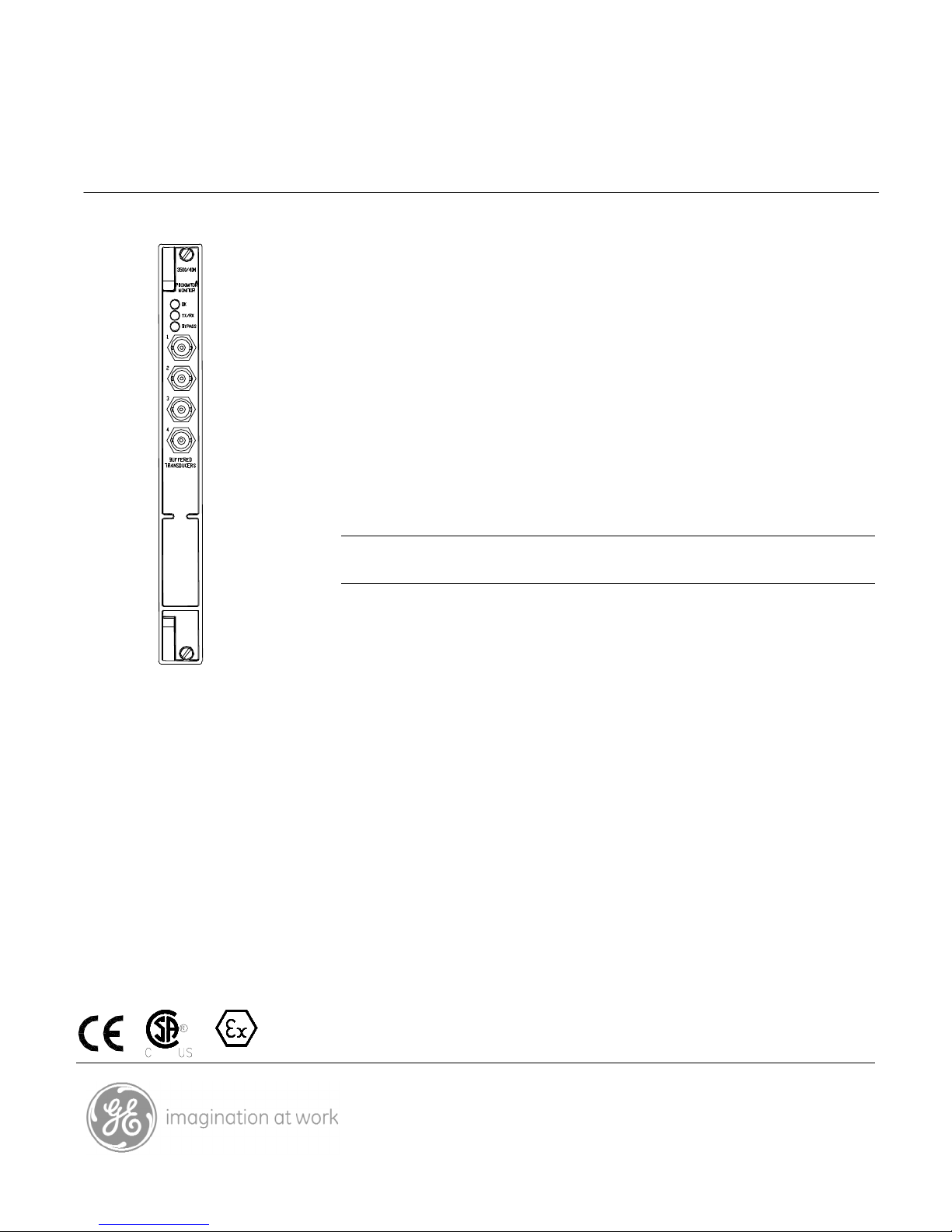
1. Main module front view.
2. Status LEDs.
3. Buffered Transducer Outputs.
4. I/O modules
5. Barrier I/O module, Internal Termination.
6. I/O Module, Internal Termination.
7. I/O Module, External Termination.
8. I/O Module, External Termination.
Figure 1
Specifications and Ordering Information
Part Number 141535-01
Rev. E (10/08)
Page 9 of 11
Page 10

REBAM® Channels
The following graphs show the maximum machine speed allowed for a monitor channel pair configured for REBAM.
The top graph assumes that both channels of the channel pair are enabled. The bottom graph assumes that only one
channel of a channel pair is enabled. The maximum speed depends on the number of rolling elements in the bearing.
The graph assumes that the rotor low-pass filter corner is set at 3.2X the shaft speed and the spike high-pass filter
corner is set at 4X the element pass frequency for the outer race (BPFO).
1-C han n el C o nfiguration
40 0 00
35 0 00
30 0 00
25 0 00
20 0 00
Ma x R P M
15 0 00
10 0 00
50 0 0
0
6 8 10 12 14 16 1 8 20 2 2 24 2 6 28 30 32 34 36 38 40
Numbe r o f E le m ents
Rotor Elem ent Pas s Sp ike
Figure 2
Specifications and Ordering Information
Part Number 141535-01
Rev. E (10/08)
Page 10 of 11
Page 11

2-C han n e l C onfigur ation
25 000
20 000
15 000
10 000
Ma x R P M
50 00
0
6 8 10 12 1 4 16 18 20 22 24 26 28 30 3 2 34 36 3 8 40
Num b e r o f E le men ts
Rotor Elem ent Pas s S pike
Figure 3
Bently Nevada is a trademark of General Electric Company.
Copyright 1999. Bently Nevada LLC.
1631 Bently Parkway South, Minden, Nevada USA 89423
Phone: 775.782.3611 Fax: 775.215.2873
www.ge-energy.com/bently
All rights reserved.
Specifications and Ordering Information
Part Number 141535-01
Rev. E (10/08)
Page 11 of 11
 Loading...