

Page 1
INTRODUCTION
Your GE Digital Answer-Phone™ is designed to give you flexibility in use, and
high quality performance. To get the most from your new telephone, we suggest
that you take a few minutes right now to read through this instruction manual. If
you have any questions or problems, consult the Table of Contents, the Troubleshooting Guide, or the Index for the solution.
TABLE OF CONTENTS
INSTALLATION AND SETUP ................................................................................................................... 2
BEFORE YOU BEGIN.......................................................................................................................2
BATTERY INSTALLATION................................................................................................................... 3
TABLETOP INSTALLATION ................................................................................................................. 4
WALL MOUNT INSTALLATION ........................................................................................................... 5
BATTERY LOW INDICATOR ................................................................................................................ 7
ANSWERING MACHINE SETUP ......................................................................................................... 7
CHOOSING/RECORDING AN OUTGOING ANNOUNCEMENT ...................................................................... 8
TELEPHONE OPERATION ...................................................................................................................... 9
FLASH BUTTON ............................................................................................................................. 9
REDIAL BUTTON .......................................................................................................................... 10
TEMPORARY TONE FEATURE .......................................................................................................... 10
MEMORY DIALING ........................................................................................................................... 11
STORING A NUMBER IN MEMORY................................................................................................... 11
DIALING A NUMBER FROM MEMORY ............................................................................................... 12
ANSWERING MACHINE OPERATION ..................................................................................................... 13
MESSAGE PLAYBACK ................................................................................................................... 13
ERASING MESSAGES DURING MESSAGE PLAYBACK .......................................................................... 13
LEAVING A MEMO ....................................................................................................................... 14
CALL SCREENING/AUTO DISCONNECT ............................................................................................. 14
TOLL SAVER FEATURE .................................................................................................................. 15
ACCESSING THE ANSWERER FROM ANOTHER LOCATION ...................................................................... 15
TROUBLESHOOTING TIPS ................................................................................................................... 16
CARE AND MAINTENANCE ................................................................................................................. 18
SERVICE ......................................................................................................................................... 18
INDEX ............................................................................................................................................ 19
LIMITED WARRANTY ......................................................................................................................... 20
CAUTION
RISK OF ELECTRIC SHOCK
DO NOT OPEN
CAUTION: TO REDUCE THE
RISK OF ELECTRIC SHOCK,
DO NOT REMOVE COVER
(OR BACK). NO USERSERVICEABLE PARTS INSIDE. REFER SERVICING
TO QUALIFIED SERVICE
PERSONNEL.
SEE MARKING ON BOTTOM / BACK OF PRODUCT
THE EXCLAMATION
POINT WITHIN THE
TRIANGLE IS A
WARNING SIGN
ALERTING YOU OF
IMPORTANT
INSTRUCTIONS
ACCOMPANYING
THE PRODUCT.
WARNING:
OR ELECTRICAL SHOCK HAZARD,
DO NOT EXPOSE THIS PRODUCT
TO RAIN OR MOISTURE.
TO PREVENT FIRE
THE LIGHTNING
FLASH AND ARROW HEAD WITHIN THE
TRIANGLE IS A
WARNING SIGN
ALERTING YOU OF
"DANGEROUS
VOLTAGE" INSIDE
THE PRODUCT.
2-9827 US IB E 2 1/31/98, 6:51 PM1
Page 2
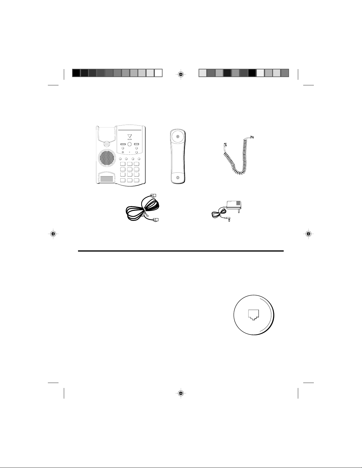
PARTS CHECKLIST
Your package should contain the following items:
ERASE
MESSAGES
ANSWER ON
PLAY
•
STOP
SKIP
REVIEW
MEMO
ANS. ON
MICBATT LOW
ANNOUNCE
REDIAL
FLASH
MEMORY DIAL
STORE
123
DEF
ABC
GHI JKL MNO
45
MEMORY LOG
6
1
27
38
49
50
Base unit
PQRS TUV WXYZ
78
OPER
0
*
6
9
#
Handset
Long handset cord
Phone line cord
AC power adapter 5-2399
2580059.12
INSTALLATION AND SETUP
Your GE Digital Answer-Phone™ can be mounted on the wall or placed on a
counter top or table top. After you decide which type of installation you want,
refer to the appropriate installation diagram.
BEFORE YOU BEGIN
MODULAR JACK REQUIREMENTS
You need a USOC: RJ11C type modular jack, similar to
the one pictured here. If you don't have a modular
jack, call your phone company to find out how to get
one installed.
2
2-9827 US IB E 2 1/31/98, 6:51 PM2
Page 3
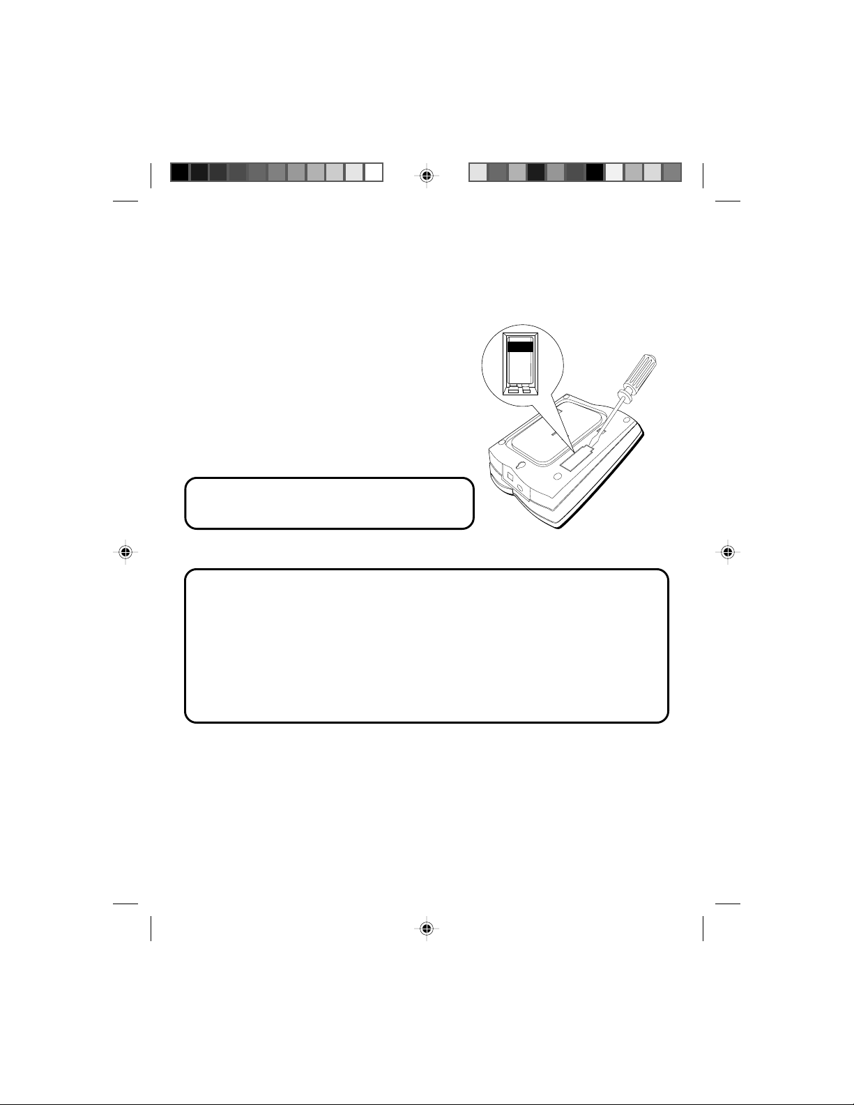
BATTERY INSTALLATION
In the event of a power loss, the 9-volt alkaline battery backup enables the
answerer to retain messages stored in memory, the outgoing announcement,
and time/day information.
1. Unplug the telephone line from the
modular jack on the wall.
2. Open the battery compartment door with a
flat tool.
3. Insert a 9-volt alkaline battery (not
included), as shown on the diagram inside
the battery compartment.
4. Snap battery compartment door into place.
NOTE: When the battery needs to be replaced,
the BATT. LOW indicator flashes.
BATTERY SAFETY PRECAUTIONS
For your safety, please follow these precautions:
• Do not recharge, disassemble, mutilate, wet, or dispose of batteries in fire.
• Keep batteries out of reach of children.
• Replace with 9V battery only (not included).
• When replacing batteries, be sure to unplug the phone line from the unit
before opening the battery compartment door and inserting the batteries.
BATTERY
2-9827 US IB E 2 1/31/98, 6:51 PM3
3
Page 4
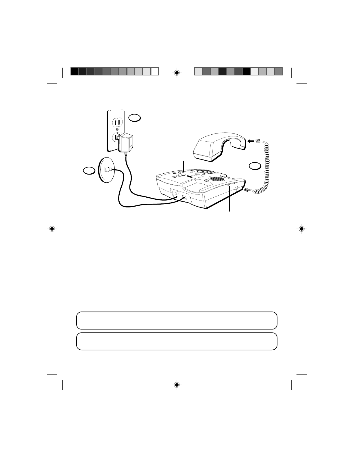
TABLETOP INSTALLATION
6
ANSWERER
volume switch
1
2
PULSE/TONE switch
RINGER volume switch
1. Plug the telephone line cord into PHONE LINE jack on the back of the unit
and the other end into a modular jack RJ11C .
2. Plug the handset cord into the handset and into the telephone jack on the
left side of the unit.
3. Set the PULSE/TONE switch on the left side of the phone to TONE if you use
touch-tone service; set it to PULSE if you have rotary service.
4. Adjust the RINGER volume switch on the left side of the phone to the
desired setting (the phone will only ring with the ringer set to LO or HI).
5. Adjust the ANSWERER volume switch on the right side of the phone to the
desired setting.
6. Plug the AC power adapter into the phone and into an AC outlet.
NOTE: Only use the Thomson 5-2399 AC adapter that came with this unit.
Using other adapters may damage the unit.
NOTE: Make sure that you have inserted the battery before installing the
phone. If you have not, see p. 3 for battery installation information.
4
2-9827 US IB E 2 1/31/98, 6:51 PM4
Page 5
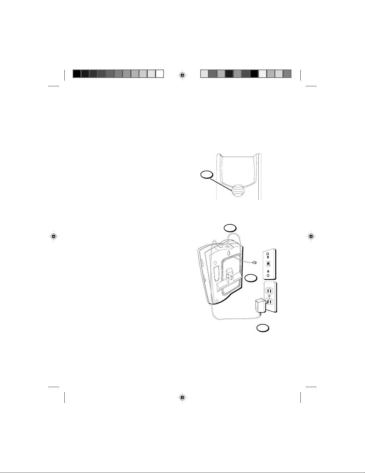
WALL MOUNT INSTALLATION
Your phone can be mounted on a wall
phone plate (not included). Before you
mount the phone on the wall, write down
the 3-digit security code that is on the
underside of the phone. You need to know
this code in order to pick up your messages from another phone.
1. Rotate the handset hook one-half turn.
2. Plug one end of the telephone line
cord into the jack marked PHONE LINE
on the back of the unit. Wrap the
excess cord around the plastic tabs.
Plug the other end of the telephone
line cord into a modular wall jack.
3. Attach the wall mount bracket by
turning the T-shaped bracket upside
down, as pictured. Then put the tabs
at the bottom of the bracket into the
matching slots near the bottom of the
unit and snap the top tab into place.
4. Plug the AC adapter into the back of
the phone and into an AC outlet.
1
2
3
4
2-9827 US IB E 2 1/31/98, 6:51 PM5
5
Page 6
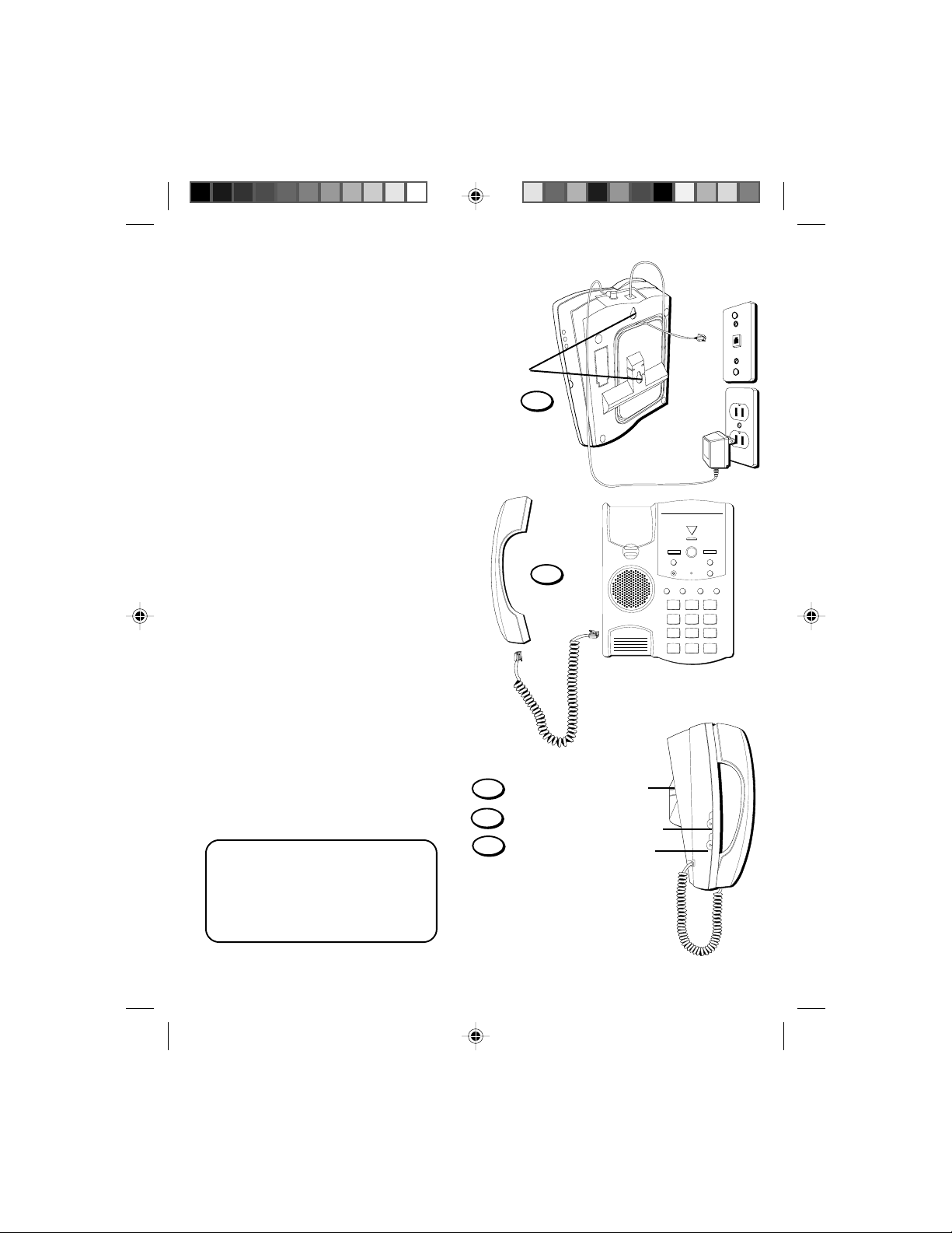
5. Slip the mounting holes over
the wall plate posts and slide
the unit down firmly into
place.
6. Plug one end of the handset
cord into the handset and the
other end into the unit. Hang
up the phone.
7. Set the PULSE/TONE switch
on the left side of the phone
to TONE if you use touch-tone
service; set it to PULSE if you
have rotary service.
8. Adjust the RINGER volume
switch on the left side of the
phone to the desired setting
(the phone will only ring with
the ringer set to LO or HI).
Mounting holes
5
ERASE
MESSAGES
ANSWER ON
PLAY
• STOP
SKIP
REVIEW
MEMO
ANS. ON
MICBATT LOW
6
MEMORY LOG
6
1
27
38
49
50
REDIAL
FLASH
123
ABC
GHI JKL MNO
45
PQRS TUV WXYZ
78
OPER
0
*
ANNOUNCE
MEMORY DIAL
STORE
DEF
6
9
#
9. Adjust the ANSWERER
volume switch on the right
side of the phone to the
desired setting.
NOTE: Make sure that you have
inserted the battery before
installing the phone. If you have
not, see p. 3 for battery installation information.
6
2-9827 US IB E 2 1/31/98, 6:52 PM6
ANSWERER volume
9
switch (right side)
8
RINGER volume switch
7
PULSE/TONE switch
OFF LO HI
RINGER
PULSE TONE
Page 7

BATTERY LOW INDICATOR
SKIP
ANS. ON
MEMO
PLAY
•
STOP
ERASE
ANNOUNCE
MICBATT LOW
REVIEW
MESSAGES
ANSWER ON
When a battery has not been installed or needs
to be replaced, the BATT. LOW indicator
flashes rapidly.
ANSWERING MACHINE SETUP
This section shows you how to set up your
answering machine to receive incoming calls.
Before you begin the setup, you must be sure
the answerer is on.
TURNING ON THE ANSWERING MACHINE
Press and hold the ANS.ON button to turn the
answering machine on and off (the unit beeps
twice and a voice prompts
"functions off"
).
"functions on"
or
MESSAGES/ANSWER ON
indicator light
NOTE: The unit takes approximately 10
seconds to emit the voice prompts
"functions on" and/or "functions off."
When the answerer is on, the MESSAGES/
ANSWER ON indicator lights. When the day
and time need to be set or the outgoing
announcement needs to be recorded, the
MESSAGES/ANSWER ON indicator light
flashes rapidly.
SETTING THE VOICE TIME/DAY
• Press and hold the DAY button to set the
day of the week.
• Press the HOUR button to set the hour
(a.m. or p.m.).
• Press the MINUTE button to set the
minute. When you hold the MINUTE
button, it advances the time in
5-minute increments.
• Press and quickly release the DAY button
to review the day/time setting.
2-9827 US IB E 2 1/31/98, 6:52 PM7
ANS. ON button
BATT. LOW indicator light
LO VOLUME HI
MINUTE HOUR DAY
MINUTE button
HOUR button
DAY button
7
Page 8

CHOOSING AN OUTGOING ANNOUNCEMENT OPTION
The outgoing announcement is the announcement callers hear when they call
you and your answering system picks up the call. You can record a personalized
outgoing announcement or use the default announcement that is programmed
into the answering system.
USING THE DEFAULT ANNOUNCEMENT
If you choose to use the default announcement, callers will hear,
your message after the tone."
This announcement also serves as the default announcement when the answering system loses power and is completely reset (unless you installed a 9-volt
battery). If you installed the battery and recorded a personalized outgoing
announcement, your answerer does not default to this announcement because
your personalized outgoing announcement is retained in memory by the
battery power.
If you recorded a personalized outgoing announcement and then decide that
you want to use the default announcement instead, press the ANNOUNCE
button and release it within 1 second after the unit beeps.
RECORDING A PERSONALIZED OUTGOING ANNOUNCEMENT
When recording your outgoing announcement, you should be about 9 inches
from the MIC, located on the front of the unit, and eliminate as much background noise as possible.
1. Press and hold the ANNOUNCE button.
2. Begin talking after you hear the tone.
3. Release the ANNOUNCE button when you're finished talking.
SAMPLE OUTGOING ANNOUNCEMENT
Hi, this is (use your name here), I can't answer the phone right now, so please leave your name,
number and a brief message after the tone, and I'll get back to you. Thanks.
"Please leave
REVIEWING THE OUTGOING ANNOUNCEMENT
You can review the outgoing announcement by pressing and quickly releasing
the ANNOUNCE button.
NOTE: You can stop the outgoing announcement by pressing STOP while the
announcement is playing.
8
2-9827 US IB E 2 1/31/98, 6:52 PM8
Page 9

TELEPHONE OPERATION
SKIP
ANS. ON
MEMO
PLAY
•
STOP
ERASE
ANNOUNCE
MICBATT LOW
FLASH
REDIAL
STORE
MEMORY DIAL
REVIEW
123
45
6
78
9
0
*
#
ABC
DEF
GHI JKL MNO
PQRS TUV WXYZ
OPER
MESSAGES
ANSWER ON
MAKING A CALL
1. Pick up the handset to get a dial tone.
2. Dial the number.
RECEIVING A CALL
Make sure that the RINGER (on the side of the
unit) is set to LO or HI.
1. Pick up the handset when the phone
rings.
2. Put handset in cradle when finished with
conversation.
FLASH BUTTON
To activate custom calling services such as
call waiting or call transfer, press the FLASH
button instead of using the hook switch.
(Custom calling services are provided by your
local phone company.)
FLASH button
9
2-9827 US IB E 2 1/31/98, 6:52 PM9
Page 10

REDIAL BUTTON
SKIP
ANS. ON
MEMO
PLAY
•
STOP
ERASE
ANNOUNCE
MICBATT LOW
FLASH
REDIAL
STORE
MEMORY DIAL
REVIEW
123
45
6
78
9
0
*
#
ABC
DEF
GHI JKL MNO
PQRS TUV WXYZ
OPER
MESSAGES
ANSWER ON
Redial the last number you called by pressing
the REDIAL button after you get a dial tone.
NOTE: Your phone's memory retains the
last phone number you dialed (as many as
32 digits). If you pressed any numbers after
dialing the phone number, (for example,
when accessing a voice-menu system) those
numbers are also redialed.
TEMPORARY TONE FEATURE
The temporary tone feature enables a pulse
phone to temporarily change to a tone phone.
People with pulse-tone (rotary) service would
use this feature in order to access voice information that requires touch-tone service, such
as getting information from a local bank or
using a voicemail system. To use temporary
tone:
1. Dial the number of the service.
2. Press the tone button ( * ) after you have
connected to the service in order to enable
touch-tone dialing.
3. When you hang up, the phone automatically returns to pulse dialing mode.
Tone button
REDIAL button
10
2-9827 US IB E 2 1/31/98, 6:52 PM10
Page 11

MEMORY DIALING
SKIP
ANS. ON
MEMO
PLAY
• STOP
ERASE
ANNOUNCE
MICBATT LOW
FLASH
REDIAL
STORE
MEMORY DIAL
REVIEW
123
45
6
78
9
0
*
#
ABC
DEF
GHI JKL MNO
PQRS TUV WXYZ
OPER
MESSAGES
ANSWER ON
Store as many as 10 numbers in memory for easy dialing. Numbers can be
stored in the numbered keys (0-9).
STORING A NUMBER IN MEMORY
1. Pick up the handset.
2. Press STORE.
3. Dial the number to be stored.
4. Press STORE followed by a Memory
Location (0-9 on the keypad).
5. Write the phone number on the memory
directory (located in the cradle area of the
base, under the plastic cover).
ADDING A PAUSE TO THE DIALING SEQUENCE
Use the REDIAL button to insert a pause in the
dialing sequence when storing a number (for
example, when you must dial 9 to get an outside
line or enter codes to access your bank's information line). Press REDIAL at the point in the
dialing sequence in which a pause is required.
For example, if you want to add a pause to the
dialing sequence when storing a number in
memory because you must dial 9 to get an
outside line:
1. Pick up the handset.
2. Press STORE.
3. Press 9.
4. Press REDIAL to add a pause and then dial
the phone number to be stored in memory.
5. Press STORE followed by a Memory
Location (0-9 on the keypad).
STORE button
MEMORY DIAL button
11
2-9827 US IB E 2 1/31/98, 6:52 PM11
Page 12

CHANGING A STORED NUMBER
Change a stored number by replacing it with a different number (see "Storing a
Number in Memory"). Be sure to update your memory directory when you
change numbers.
DIALING A NUMBER FROM MEMORY
You can dial numbers from memory when using the handset. When you get a
dial tone, press the MEMORY DIAL button followed by the Memory Location
(0-9) for the number you want to dial.
CAUTION: If you make test calls to emergency numbers, remain on the line
and explain the reason for the call. Also, make these calls in off-peak hours,
such as early morning or late evening.
12
2-9827 US IB E 2 1/31/98, 6:52 PM12
Page 13

A
NSWERING
M
ACHINE OPERATION
This section discusses the buttons and features on the answering machine.
ERASE button
REVIEW button
MEMO button
MESSAGES
REVIEW
MEMO
PLAY
ERASE
MICBATT LOW
•
STOP
ANSWER ON
SKIP
ANS. ON
ANNOUNCE
PLAY • STOP button
SKIP button
ANS. ON button
ANNOUNCE button
MIC
MESSAGE PLAYBACK
The MESSAGES/ANSWER ON indicator light lets you know when somebody has
left a message. When you have new messages the light blinks. If you have old
messages that have not been erased, the light stays on. To hear messages,
press and release the PLAY•STOP button. Incoming messages are limited to 3
minutes each. Press and hold PLAY•STOP for 2 seconds to hear only new
messages. (If no new messages, old messages will play).
While a message is playing, you can do the following:
• Press PLAY•STOP to stop message playback.
• Press and release REVIEW to restart the current message; continue to press
and release REVIEW to go to previous messages.
• Press and hold REVIEW to review current message.
• Press and release SKIP to go to the next message.
• Press and hold SKIP to fast forward through current message.
ERASING MESSAGES DURING MESSAGE PLAYBACK
Press and release the ERASE button to erase the message that is playing.
NOTE: Messages erased during playback cannot be restored.
2-9827 US IB E 2 1/31/98, 6:52 PM13
13
Page 14

TOTAL MESSAGE ERASE
You can erase all the messages from memory by pressing and holding the
ERASE button when the unit is not playing messages (the unit beeps to confirm
the messages are erased). Note that total message erase cannot be completed if
there are any unplayed messages.
NOTE: If you hear several high-pitched beeps, your answerer has not erased the
messages because some of them or all of them have not been played.
You can restore messages erased this way by pressing the PLAY•STOP button—
but only if you haven‘t activated any other answerer functions or received new
messages after erasing the messages.
LEAVING A MEMO
Leaving a memo is just like recording an outgoing announcement, except you
use the MEMO button instead of the ANNOUNCE button.
1. Press and hold MEMO.
2. When you hear a beep, continue holding MEMO and leave your message.
3. Release MEMO when you finish your message.
The memo is included in the message count represented by the number of
times the MESSAGES/ANSWER ON indicator light flashes.
CALL SCREENING/AUTO DISCONNECT
Because the answerer automatically stops recording when an extension phone
is picked up (Auto Disconnect feature), you can screen incoming calls. Listen as
the caller leaves a message and pick up the handset (or any extension phone) if
you want to talk to that caller.
M
EMORY FULL
When the memory is full, you must erase old messages so that there is room in
the memory for new messages.
If the memory is full, the unit answers on the 10th ring and the MESSAGES/
ANSWER ON light flashes rapidly. When using the remote access feature, you
can enter your security code and then access your messages.
NOTE: The unit answers on the 10th ring when it is turned off or the memory is
full. To access the answerer, enter the 3-digit security code after the beep. If
memory is full, play messages and erase some of them to restore memory. If the
answerer is off, press 6 to turn it on.
14
2-9827 US IB E 2 1/31/98, 6:52 PM14
Page 15

A
CCESSING THE ANSWERER FROM ANOTHER LOCATION
You can access your answering machine from a touch-tone phone by
entering the three-digit, security code after you hear the announcement.
The security code is located on the underside of your telephone.
1. Dial the phone number for the answering machine.
2. Enter the 3-digit security code after you hear the tone.
3. Follow the voice menu instructions to perform the answerer functions.
The remote feature enables you to perform the following functions:
To Press this Button
Play message 1
Repeat message 8 (while messages are playing)
Play previous message 7 (while messages are playing)
Stop message playback 3 (while messages are playing)
Erase message 0 (while messages are playing)
Skip message 9 (while messages are playing)
Turn answerer off 5
Turn answerer on 6
Record new announcement 8
Leave a message 7
Play outgoing announcement 2
TIP: You can bypass the outgoing announcement by pressing any numbered key
on the keypad while the announcement is playing. Then, after the beep you can
enter your security code to access the answering machine.
TOLL SAVER FEATURE
If you call to retrieve messages and there are no saved messages or new
messages, the unit answers on the 5th ring. If there are new messages, the unit
answers on the 2nd ring. If you're calling long distance or from a pay phone to
pick up your messages, you can hang up after 3rd ring and save the cost of the
call.
15
2-9827 US IB E 2 1/31/98, 6:52 PM15
Page 16

TROUBLESHOOTING TIPS
TELEPHONE PROBLEM
No dial tone
Can't dial out
Phone doesn’t ring
Light and tone feedback
flutter when dialing in
pulse mode.
Can’t be heard by
other party
Memory dialing
problems
SOLUTION/EXPLANATION
• Check hook switch to make sure it pops up.
• Make sure TONE/PULSE is set to correct
position.
• Unplug the phone, wait 30 seconds, and
plug the phone back in.
• Check RINGER VOLUME.
• Could have too many phones on one line.
(See FCC information regarding REN)
• This is normal as power is fluctuating with
phone outpulsing.
• Make sure phone cord is securely plugged in.
• Make sure you entered numbers correctly.
(See "Memory Dialing.")
16
2-9827 US IB E 2 1/31/98, 6:52 PM16
Page 17

ANSWERING MACHINE PROBLEM SOLUTION/EXPLANATION
Can’t hear messages
Time/Day Stamp
stuck at 1 a.m Monday
Answers on 10th ring
Incoming messages
are incomplete
Won’t respond to
commands when
you call machine from
another location
Answer function
operates erroneously
or not at all.
• Adjust answerer volume (p.4)
• Set the time/day clock (p. 7).
• Make sure answerer is turned on.
• Memory is full. Play messages and
erase them. (p. 14)
• Was an extension phone picked up
while the caller was leaving a message?
• Memory is full.
• You accidentally pressed the
PLAY•STOP button during playback and
stopped the message.
• Must use a tone-dial phone.
• Must enter correct security code (p. 15)
• Did the unit hang up? If you take no
action for a period of time, it automatically hangs up.
• Unplug the power cord from the back of
the unit and plug it back in to reset the
answerer.
2-9827 US IB E 2 1/31/98, 6:52 PM17
17
Page 18

CARE AND MAINTENANCE
To keep your GE telephone working and looking good, follow these few simple
guidelines:
• Avoid putting the phone near heating appliances and devices that generate
electrical noise. (i.e., motors, fluorescent lamps.)
• Phone should not be exposed to direct sunlight or moisture.
•
Avoid dropping the handset and other rough treatment.
• Clean telephone with a soft cloth. (Remember to first unplug the phone
from the wall outlet.)
• Never use a strong cleaning agent or abrasive powder, as this will
damage the finish.
• Retain the original packaging for future use.
SERVICE
The FCC requires this product be serviced only by the manufacturer or its
authorized service agents. In accordance with FCC requirements, changes or
modifications not expressly approved by Thomson Consumer Electronics could
void the user’s authority to operate this product. For instructions on how to
obtain service, refer to the warranty included in this guide or call customer
service's telephone number: 800-448-0329.
Attach your sales receipt to the booklet for future reference or jot down the date
this product was purchased or received as a gift. This information will be
valuable if service should be required during the warranty period.
Purchase date
Store Name
18
2-9827 US IB E 2 1/31/98, 6:52 PM18
Page 19

INDEX
A
ANS. ON button 7
Answering machine setup 7
Accessing answering machine from
another location 15
B
Battery Installation 3
Battery safety precautions 3
BATT. LOW indicator 7
C
Care and maintenance 18
E
ERASE button 13
Erasing messages 13, 14
F
FLASH button 9
H
Handset 2
M
Memo 14
Memory dialing
storing a number 11
dialing a stored number 12
Message playback 13
Modular jack 2
O
Outgoing announcement 8
recording 8
reviewing 8
P
Parts checklist 2
Pulse (rotary) service 4, 6, 10
PULSE/TONE switch 4, 6
R
REDIAL button 10
Remote access
from another location 15
Review an outgoing announcement 8
REVIEW button 13
RINGER volume switch 4, 6
S
Security code 15
Service 18
Setup 2-7
SKIP button 13
STOP button 13
T
Tabletop installation 4
Temporary tone feature 10
Time/Day stamp, setting up 7
Troubleshooting tips 16
W
Wall mount installation 5
2-9827 US IB E 2 1/31/98, 6:52 PM19
19
Page 20

LIMITED WARRANTY
What your warranty covers:
• Any defect in materials or workmanship.
For how long after your purchase:
• Two years.
(The warranty period for rental units begins with the first rental or 45 days from date of shipment
to the rental firm, whichever comes first.)
What we will do:
• Provide you with a new, or at our option, a refurbished unit.
• The exchange unit is under warranty for the remainder of the original product’s warranty
period.
How to make a warranty claim:
• Properly pack your unit. Include any cables, etc., which were originally provided with the
product. We recommend using the original carton and packing materials.
• Include in the package evidence of purchase date such as the bill of sale. Also print your name
and address and a description of the defect. Send standard UPS or its equivalent to:
Thomson Consumer Electronics, Inc.
Product Exchange Center
32 Spur Drive
El Paso, Texas 79906
• Pay any charges billed to you by the Exchange Center for service not covered by the warranty.
• A new or refurbished unit will be shipped to you prepaid freight.
What your warranty
• Customer instruction. (Your Owner’s Manual provides information regarding operating instruc-
tions and user controls. For additional information, ask your dealer.)
• Installation and set-up service adjustments.
• Batteries.
• Damage from misuse or neglect.
• Products which have been modified or incorporated into other products.
• Products purchased or serviced outside the USA.
• Acts of God, such as but not limited to lightning damage.
Product Registration:
• Please complete and mail the Product Registration Card packed with your unit. It will make it
easier to contact you should it ever be necessary. The return of the card is not required for
warranty coverage.
How state law relates to this warranty:
• This warranty gives you specific legal rights, and you may have other rights which vary from
state to state.
If you purchased your product outside the USA:
• This warranty does not apply. Contact your dealer for warranty information.
does not
cover:
3
Model 2-9827A
347A8329-0001 (Rev. 2 E/S)
97-15
Printed in China
2-9827 US IB E 2 1/31/98, 6:52 PM20
P.O. Box 1976, Indianapolis, IN 46206
© 1997 Thomson Consumer Electronics, Inc.
Trademark(s) ® Registered
Marca(s) Registerada(s)
 Loading...