

Page 1
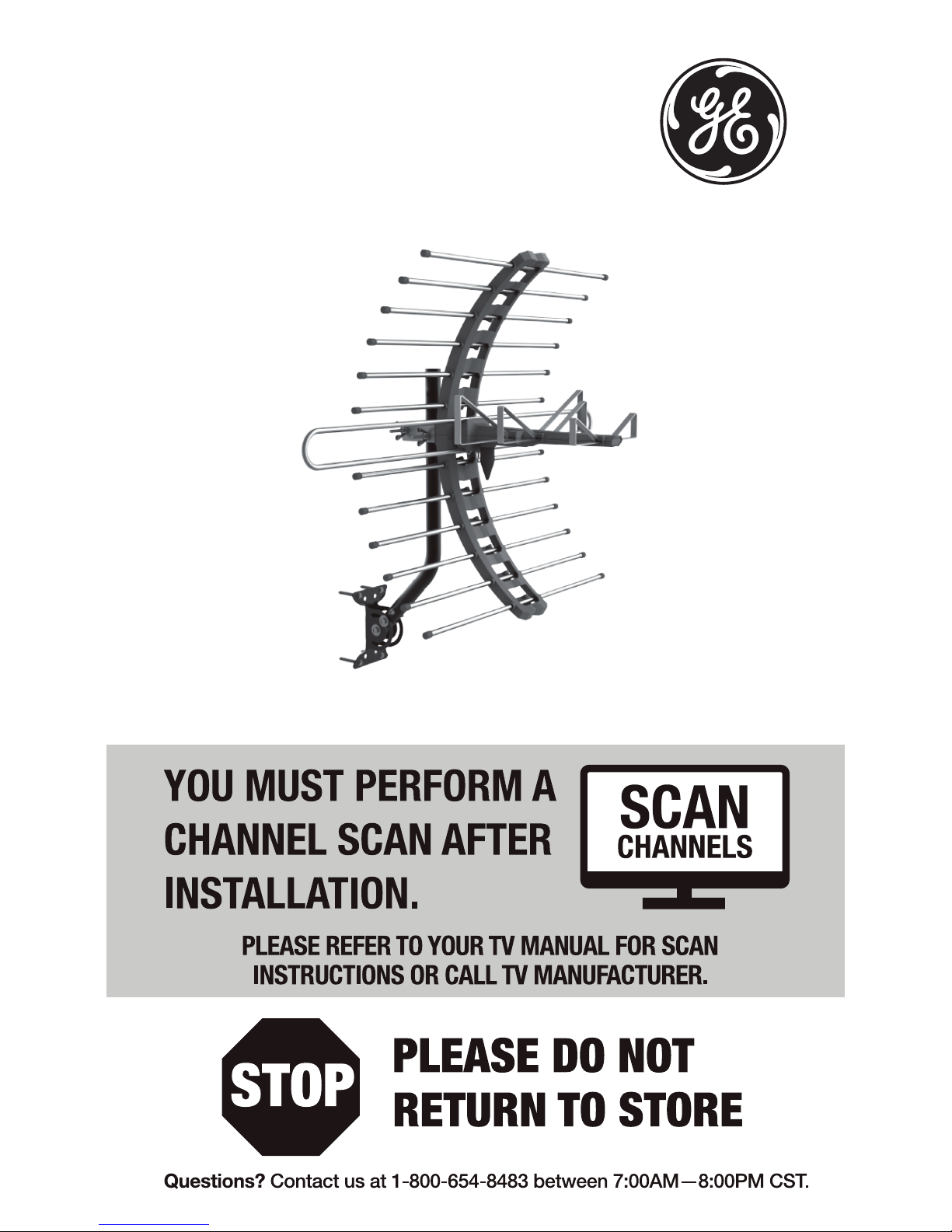
Outdoor Antenna
User’s Manual
Page 2

2
WARNING: INSTALLATION OF
THIS PRODUCT NEAR POWER
LINES IS DANGEROUS, FOR
YOUR SAFETY, FOLLOW THE
INSTALLATION DIRECTIONS.
WATCH FOR WIRES! YOU CAN
BE KILLED IF THIS ANTENNA
COMES NEAR ELECTRIC POWER
LINES. READ INSTRUCTIONS!
Page 3

3
TABLE OF CONTENTS
IMPORTANT SAFETY INSTRUCTIONS ....................................................4
SELECT AND MEASURE YOUR INSTALLATION SITE .........................5
CHOOSE A MOUNT TYPE ............................................................................6
ASSEMBLY INSTRUCTIONS - Parts List ................................................. 7
ASSEMBLY INSTRUCTIONS - Assembling the Antenna ................9
ASSEMBLY INSTRUCTIONS - Ground the Antenna Mount ....... 13
EASY INSTALLATION GUIDES .................................................................17
ANTENNA HELPFUL TIPS .........................................................................18
Page 4

4
IMPORTANT SAFETY INSTRUCTIONS:
• NEVER touch ANYTHING or ANYONE in contact with a
power line. You can be electrocuted. In case of an accident
or emergency, call 911 immediately for help.
• Inspect your installation site carefully for power lines.
Make sure there is no possibility the antenna, its
mounting structure or your ladder can come into
contact with power lines. Be sure to consider what can go
wrong during installation.
• KEEP the distance between power lines and the antenna
and its mounting structure at least 2 times the combined
height of the antenna and mounting structure added
together. In the event the antenna falls, during or after
assembly, there must be sufficient distance to ensure it
does not come into contact with the power lines.
• KEEP your ladder, antenna and antenna mounting
structure, such as mast, pole, mount, far away from power
lines at all times.
• GROUND the antenna and the antenna mounting
structure in accordance with the NEC electrical
code, all state and local electrical code requirements
• COMPLETE the antenna assembly on the ground prior to
mounting.
• DO NOT use a metal ladder or install the antenna on a
windy day. If the antenna or mast starts to fall, drop them.
• EXERCISE caution when working on a roof.
• APPLY the danger label included to the base of the
antenna mounting structure.
• INFORM others of the danger of touching power lines or
touching other objects in contact with power lines.
• CONTACT a professional installer in your area to do the
antenna installation if you are unsure how to safely install
and ground this antenna.
Page 5

5
SELECT AND MEASURE YOUR INSTALLATION SITE
Key things to consider in choosing the antenna installation
site are:
1) Choose a SAFE location that is far away from power lines.
Keep the distance between power lines and the
antenna and its mounting structure at least 2 times the
combined height of the antenna and its mounting structure
added together. Refer to the Important Safety
Instructions.
2) Determine the location of the broadcast towers in your
area. You will need to point the small end of your antenna
toward those towers. There are online resources such
as www.antennaweb.org that can help you identify your
local broadcast towers and the channels you can expect to
receive.
3) Check your local, city and state building and electrical
codes. Make sure your planned installation is safe and in
compliance with all applicable codes, rules and
regulations.
Page 6
6
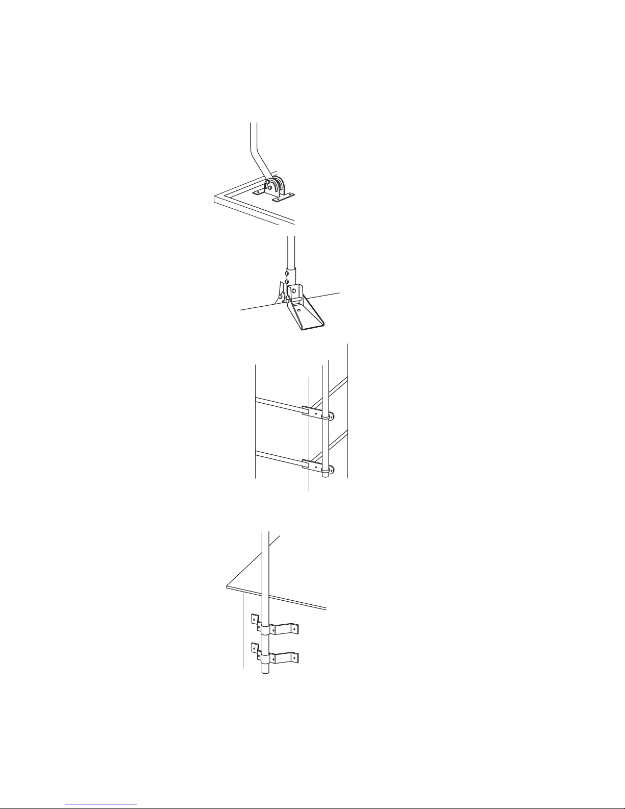
CHOOSE A MOUNT TYPE:
Some examples of common mounting options are shown
below. Follow the installation instructions for the mount you
will use.
1) J-Mount:
(Provided)
2) Ridge Mount:
(Not provided)
3) Chimney Mount:
(Not provided)
4) Wall Mount:
(Not provided)
IF YOU ARE UNSURE OR DO NOT FEEL CAPABLE
OF INSTALLING THIS ANTENNA, CONTACT
A PROFESSIONAL INSTALLER IN YOUR AREA.
Page 7
7
ASSEMBLY INSTRUCTIONS:
Thank you for purchasing the GE 29884 Outdoor Antenna.
This antenna is a sturdy, high-performing antenna designed
to receive UHF and VHF broadcasted signals. The small,
compact design allows you to install the antenna almost
anywhere on the outside of your house.
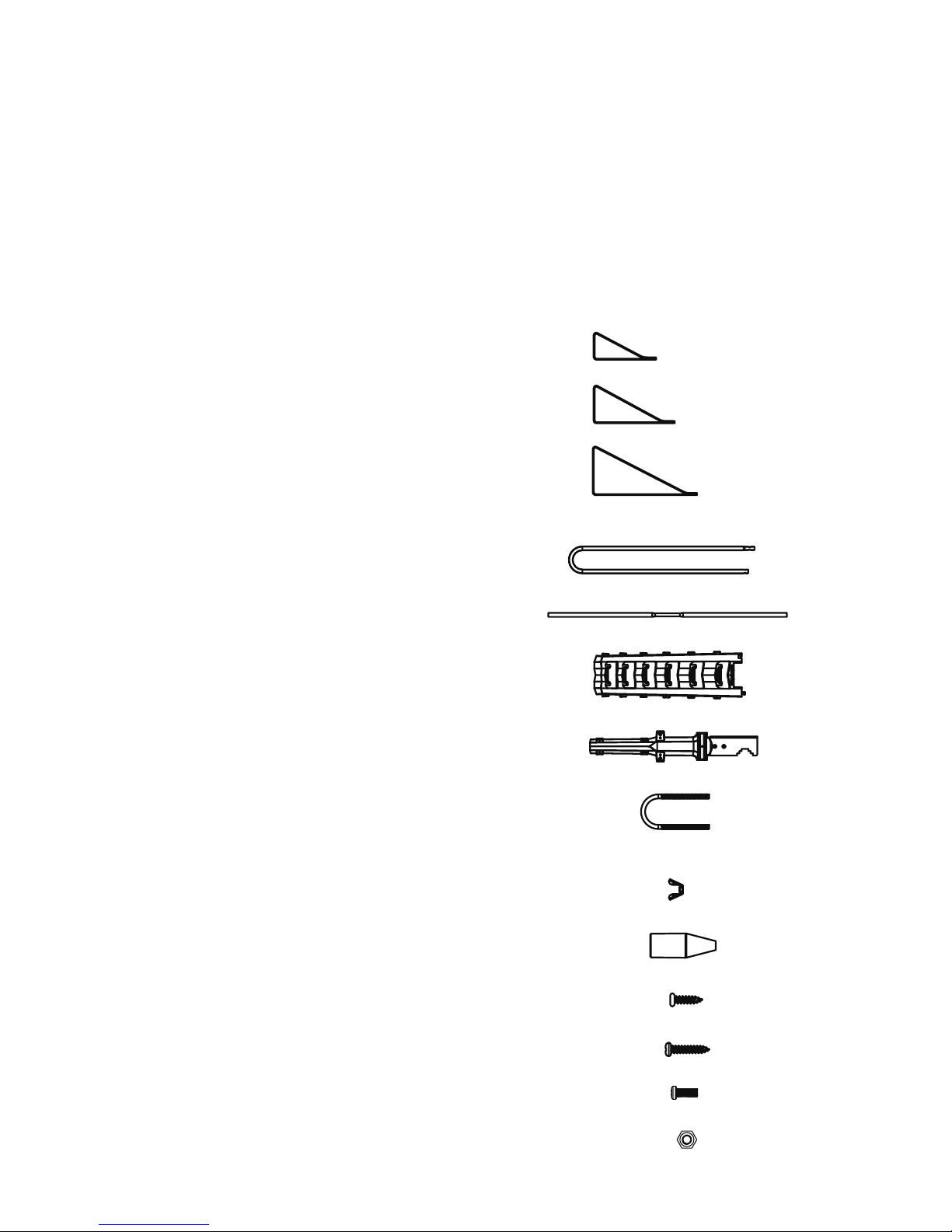
PARTS LIST:
1) Director A 2 ea.
2) Director B 2 ea.
3) UHF Dipole C 2 ea.
4) VHF Dipole 2 ea.
5) Reflector Rods 12 ea.
6) Reflector Bracket 2 ea.
7) Main Mast 1 ea.
8) “U” Bolt 1 ea.
9) Wing Nuts 2 ea.
10) Rubber Boot 1 ea.
11) M3 X 10mm Sheet Metal Screw 4 ea.
12) M3 X 14mm Sheet Metal Screw 1 ea.
13) M3 X 12mm Bolt 2 ea.
14) M3 Nuts 2 ea.
Page 8
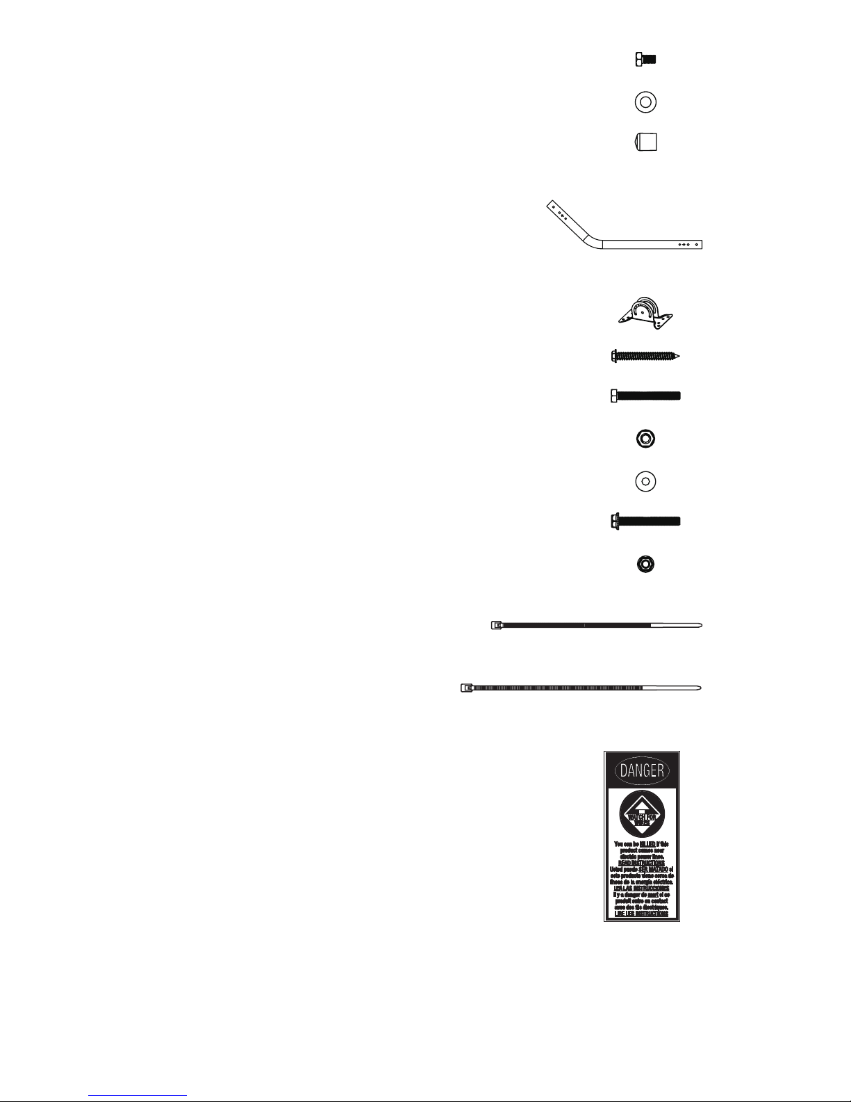
8
15) M6 X 10mm Bolt 2 ea.
16) M6 X 12mm Washers 2 ea.
17) Rubber End Caps 24 ea.
18) “J” Mast (15/16” or 2.5 cm) 1 ea.
19) Mounting Bracket 1 ea.
20) ¼ X 2” Lag Screws 4 ea.
21) M6 X 50mm Bolts 2 ea.
22) M6 Locking Nuts 2 ea.
23) M6 Washers 4 ea.
24) M5 X 40mm Bolt 1 ea.
25) M5 Nut 1 ea.
26) Small Zip Tie 1 ea.
27) Large Zip Tie 2 ea.
28) Danger Label 1 ea.
Page 9
9
ASSEMBLING THE ANTENNA:
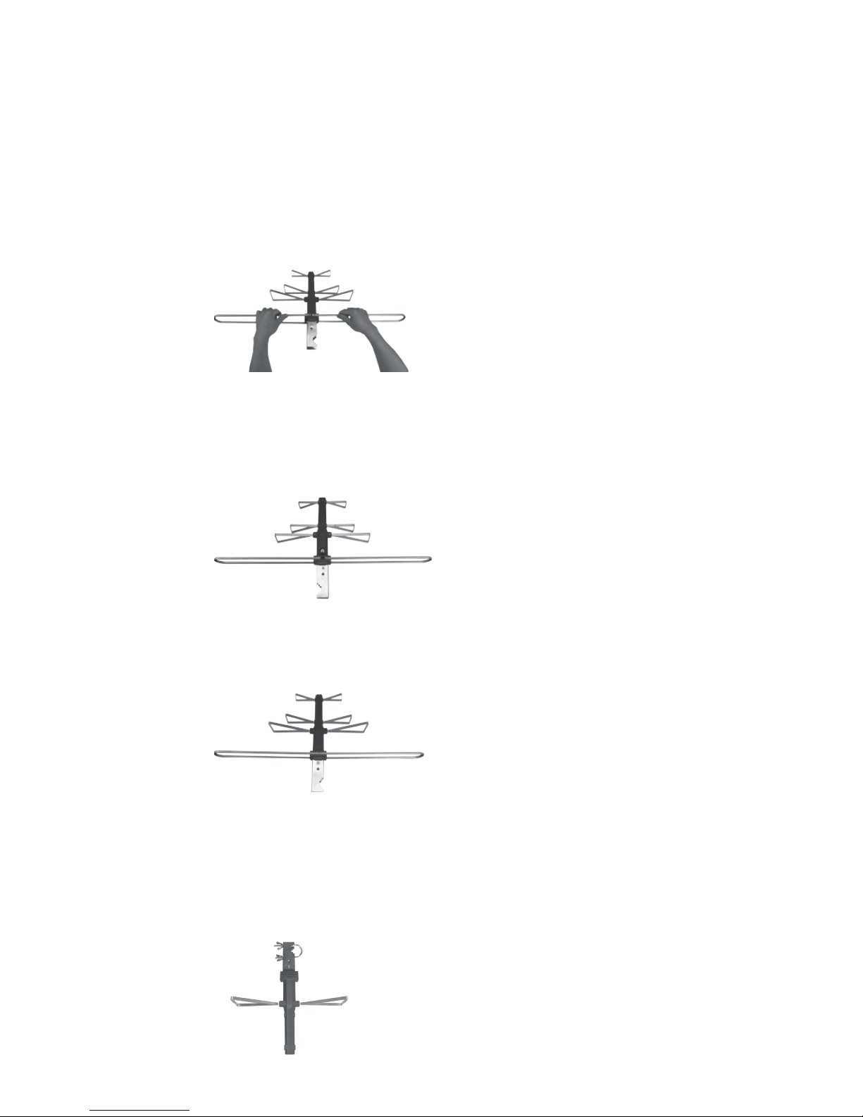
1) Connecting the VHF Dipole
a) Remove the foam block covering the bolts and nuts from the
antenna Main Boom.
b) Remove the nuts and lock washers from the bolts.
c) Connect together the two halves of the VHF Dipoles, one end is
tapered to slide into the other half as illustrated in (Fig. 1a).
Fig. 1a
d) Connect the VHF Dipoles onto the antenna Main Boom and slide
the two open ends over the protruding bolts from the antenna
Main Boom. Secure with the two tooth washers and nuts
previously removed. Do not overtighten the nuts onto the bolts
(Fig. 1b).
Fig. 1b
e) Using the M3 X 14mm Sheet Metal Screw, secure the other
side of the VHF Dipole to the antenna Main Boom (Fig. 1c).
Fig. 1c
2) Connecting the UHF Dipoles: (Part Labeled “C,” “B” and “A”)
a) On the antenna Main Boom, you will see the letter “C” embossed
on the boom; attach the Dipoles labeled “C” to the Main Boom
using the two M3 X 12mm Bolts and Nuts. (The “C” from the
Dipoles should be facing up.) Do not overtighten the bolts (Fig. 2a).
Fig. 2a
Page 10
10
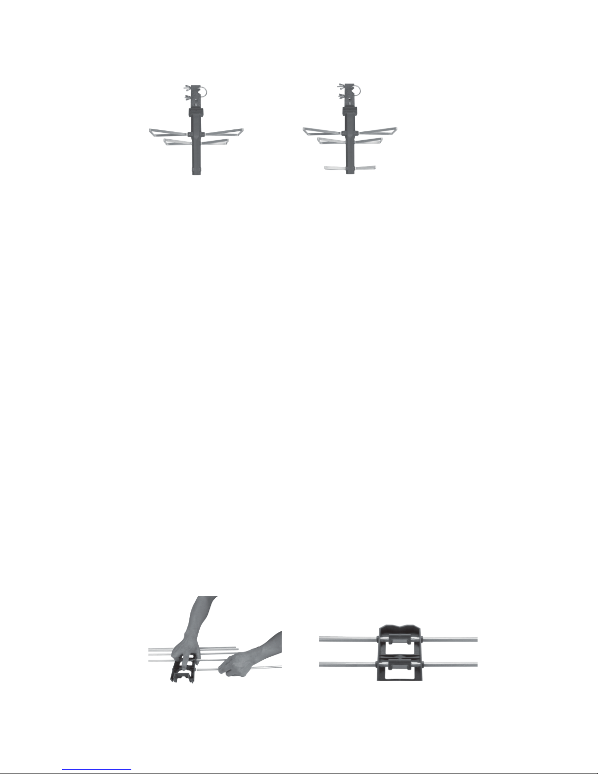
b) Attach in the same manor the Dipoles “B” and “A” using the
M3 X 8mm Sheet Metal Screws, being careful not to
overtighten the screws (Fig. 2b & Fig. 2c).
Fig. 2b Fig. 2c
3) Assembling the Reflector
Note: Before assembling the Reflector, you will notice that the holes on the
Reflector Brackets are not perfectly round and the center of the Reflector
Rods is slightly flat. You will also see to indentations on each rod spaced
about 1.5” apart on all 12 rods; these indentations are there to help in
properly aligning the rods evenly in the Reflector Brackets.
When assembling the rods into the Reflector Brackets, do not force the
Reflector Rods into the brackets. Be careful in this part of the assembly so
that you do not bend the Reflector Rods.
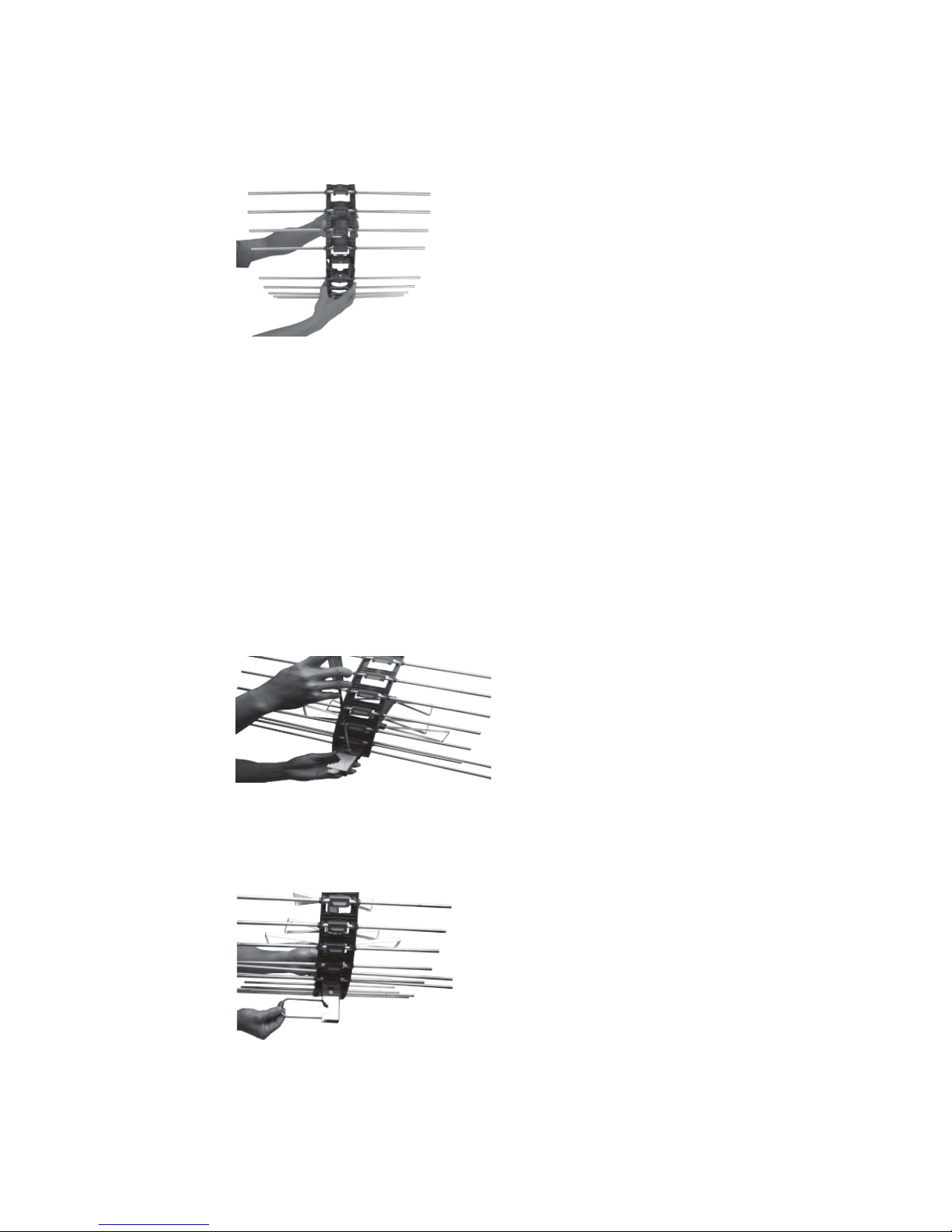
a) Place one half of the Reflector Bracket on a flat surface with the
clamping tabs facing up and the open end facing away from you.
b) Using your thumb, hold down the Reflector Bracket and with your
index finger; carefully lift up on the clamping tab.
c) With your other hand, slide one of the Reflector Rods into the
bracket being sure to slide the Reflector Rod under the clamping
tab, the rod will stop sliding in when the flat part of the rod reaches
the opening on the Reflector Bracket. At this point, slightly twist
the reflector rod until the flat portion of the rod aligns with the flat
part of the hole on the Reflector Bracket. Finish sliding in the
Reflector Rod until the clamping tab is in the middle of the two
indentations (Fig. 3a & Fig. 3b).
Fig. 3a
Fig. 3b
d) Repeat the above process for the other five Reflector Rods and the
second half of the Reflector Bracket and rods.
Page 11
11
e) Install the Rubber End Caps after all the Reflector Rods are
assembled into the Reflector Brackets.
f) Connect the two assembled halves of the Reflector Brackets
together by aligning the connecting tabs and sliding the halves
together until the halves are evenly aligned (Fig. 3c).
Fig. 3c
4) Assembling the Assembled Antenna Main Boom to the Assembled
Reflector
a) Slide the metal end of the antenna Main Boom through the center
of the Reflector from the concaved side of the Reflector until the
bolt holes align with the bolt holes on the Reflector Brackets.
b) Slide the two M6 X 12mm Flat Washers onto the two M6 X 10mm
Bolts.
c) Screw in the bolts through the Reflector Bracket top and bottom
into the antenna Main Boom until bolts are tight. The finished
assembly should look like the illustration in (Fig. 4a).
Fig. 4a
d) Remove the Wing Nuts from the “U” Bolt.
e) Insert the “U” Bolt through the metal portion of the antenna Main
Boom from the jagged notched side of the antenna Main Boom
(Fig. 4b).
Fig. 4b
f) Thread the Wing Nuts partially back onto the “U” Bolt; do not
thread Wing Nuts all the way down at this time.
Page 12

12
5) Installing the Assembled Antenna:
a) Locate a position on the house that is far away from the power
lines. Refer to the Important Safety Instructions.
b) Secure the Mounting Bracket to the location selected for the
antenna. The 1/4 X 2” Lag Screws have been provided for some
installations.
c) Connect the “J” mount to the Mounting Bracket (Fig. 5a) using the
M6 x 50mm Bolts, M6 Locking Nuts and M6 Washers.
Fig. 5a
d) Position the J-Mount perpendicular to the ground
using a small level.
e) Slide the Antenna onto the “J” Mount (Fig. 5b). Point
the small end of the antenna in the direction of
the broadcast towers you wish to receive. Tighten
the Wing Nuts on the “U” Bolt when the antenna is in
the desired position.
Fig. 5b
Page 13

13
6) Antenna Grounding & Connecting Coax Cables
The National Electric Code (NEC) requires your outdoor antenna
installation to be properly grounded. This involves grounding both
the antenna and the antenna mounting structure. This helps
protect you and your property in the event of static build up on the
antenna or lightning near your home.
Note: If you previously had a satellite system installed at your
home, you may be able to use some of the parts from this system
for your antenna installation.
a) Ground the Antenna Mount: Attach a #8
aluminum or a #10 copper grounding wire to the
antenna mounting structure, for example pole, mast,
tower, etc. In some cases, a bolt on the mount can be
used for making this connection. When using the “J”
Mount provided, use the M5 Bolt and M5 Nut in
the hole on the “J” Mount located just above the
Mounting Bracket to make this connection (Fig. 6a).
Fig. 6a
Tighten this connection securely. Ensure there is a
good electrical connection between your mounting
structure and grounding wire. Running the wire
as straight as possible and using stand-off insulators
spaced from four (4) to six (6) feet apart, attach the
grounding wire to an acceptable building ground
location.
Page 14

14
Examples of acceptable building grounding locations
are:
• The building or structure grounding electrode
system as covered in 250.50 in the NEC
• Grounded interior metal water piping system, within
5ft. from its point of entrance to the building
• Grounded nonflexible metallic power service
raceway
• Service equipment enclosure, the grounding
electrode conductor or the grounding electrode
conductor metal enclosure of the power service
• An 8-foot grounding rod driven into the ground
can be used as long as it is connected to the
central building ground by a #6 or heavier bonding
wire
Refer to the NEC sections 250 and 810 for other
acceptable grounding methods.
b) Connect one end of a coax cable to the antenna and
the other end to a 75 ohm grounding block. Below
(Fig. 6b) is an example of a 75 ohm grounding block.
Fig. 6b
If you make your own coax cable, be sure to slide the
Rubber Boot over the cable before you place the
connectors on the cable. Once you have attached the
cable to the antenna, slide the Rubber Boot into the
round channel on the Main Housing Unit.
Page 15

15
If you are using a pre-built cable that has connectors,
follow these steps.
i. Cut 4 slits spaced evenly apart at the narrow tip of the
provided Rubber Boot approximately ¼” in length.
(Fig. 6c)
Fig. 6c
ii. Run the coax cable through the narrow end of
the Rubber Boot and attach the cable to the
antenna.
iii. Slide the Rubber Boot into the round channel on
the Main Housing Unit.
iv. Using the Small Zip Tie, wrap the tie around the
narrow tip of the Rubber Boot, around the four
slits and pull the tie tight.
Use a second coax cable and connect one end to
mating port of the first coax cable on the 75 ohm
grounding block and run the other end into your home
for making the connection to your TV. The 75 ohm
grounding block needs to be placed as close as
possible to the point where the second coax cable enters
your home
Note: Leave enough slack in the coax cable to create a
drip loop so that moisture cannot enter the house. You
will also need to seal the coax cable entry point into
your house with an exterior caulk.
Page 16

16
c) Ground the 75 OHM Grounding Block: Connect
a #8 aluminum or #10 grounding wire to a screw
terminal provided on the 75 ohm grounding block.
Connect the other end of the wire to an acceptable
building ground location. Refer to Step a) above for
acceptable building grounding locations.
Be sure to double check all your connections after
your installation is complete. Ensure there are good
electrical connections of your grounding wires and
coax cables. See Fig. 6d below for an example of a
properly grounded antenna installation.
Fig. 6d
If you are unsure how to properly ground your antenna,
contacta professional installer in your area.
Page 17

17
EASY INSTALLATION FOR ANALOG TVS WITH SET-TOP BOX
1) Connect the coax cable from the antenna to your set-top
box antenna input. Then connect another coax cable (not
included) to the antenna output on the set-top box.
2) Connect the other end of that cable to the antenna input
on your TV.
3) Following your set-top box instruction manual to scan for
channels on your set-top box.
EASY INSTALLATION FOR TODAY’S HDTVS
1) Connect the coax cable from the antenna to the antenna
input on your TV.
2) Follow your TV’s instruction manual to scan for channels
on your television.
DANGER LABEL APPLICATION
If your antenna mounting structure, such as a mast, J-Mount
or pole, does not have a danger label, apply the danger label
provided to the base of the mounting structure in a clearly
visible location.
ANTENNA REMOVAL
Inspect the area carefully for power lines. Pay attention for
any new power lines that may have been installed. Make sure
there is no possibility the antenna, its mounting structure or
your ladder can come in contact with power lines. Be sure to
consider what can go wrong during antenna removal. Repeat
the steps for antenna installation but in reverse order.
Page 18

18
ANTENNA HELPFUL TIPS
Maximize the number of channels you receive by placing the
antenna in several different locations to see which location
provides the best reception and the maximum number of
channels. Be sure to run a new channel scan on your TV in
each position. Refer to the instruction manual that came with
your TV if you are not sure how to do this.
Position or mount the antenna as high as possible for best
performance.
Visit www.antennaweb.org or www.dtv.gov and look for the
DTV Reception Maps to determine the available television
stations and location of the broadcast towers in your area.
FOR FURTHER ASSISTANCE, CALL 1-800-654-8483 FOR
TECHNICAL SUPPORT.
29884 V2
08/30/17
MADE IN CHINA
GE is a trademark of General Electric Company and is
under license by Jasco Products Company LLC, 10 E.
Memorial Rd., Oklahoma City, OK 73114.
This Jasco product comes with a limited-lifetime
warranty. Visit www.byjasco.com for warranty details.
Questions? Contact us at 1-800-654-8483 between
7:00AM—8:00PM CST.
Page 19

Antena para
exteriores
Manual del usuario
Page 20

20
ADVERTENCIA: INSTALAR ESTE
PRODUCTO CERCA DE CABLES
ELÉCTRICOS ES PELIGROSO.
POR SU SEGURIDAD, SIGA
LAS INDICACIONES DE
INSTALACIÓN.
¡PRESTE ATENCIÓN A LOS
CABLES ELÉCTRICOS! EL
CONTACTO DE ESTA ANTENA
CON ALGÚN CABLE ELÉCTRICO
PUEDE CAUSARLE LA MUERTE.
¡LEA LAS INSTRUCCIONES!
Page 21

21
ÍNDICE
INSTRUCCIONES DE SEGURIDAD IMPORTANTES ..........................................4
SELECCIONE Y MIDA EL LUGAR DE LA INSTALACIÓN .................................5
ELIJA UN TIPO DE MONTAJE ................................................................................... 6
INSTRUCCIONES DE ENSAMBLADO: Lista de partes .................................. 7
INSTRUCCIONES DE ENSAMBLADO:
Cómo ensamblar la antena .................................................................................... 9
INSTRUCCIONES DE ENSAMBLADO:
Conexión a tierra del montaje de la antena ............................................... 13
GUÍAS PARA UNA INSTALACIÓN FÁCIL ............................................................17
SUGERENCIAS ÚTILES RELACIONADAS CON LA ANTENA ..................... 18
Page 22

22
INSTRUCCIONES DE SEGURIDAD IMPORTANTES
• NUNCA toque NADA ni a NADIE que esté en contacto con un
cable eléctrico. Podría electrocutarse. En caso de accidente o
emergencia, llame al 911 de inmediato para obtener ayuda.
• Inspeccione el sitio de la instalación cuidadosamente para ver
si hay cables eléctricos. Asegúrese de que no haya ninguna
posibilidad de que la antena, la estructura sobre la que está
montada o su escalera puedan tomar contacto con algún
cable eléctrico. Piense en todo aquello que podría salir mal
durante la instalación.
• MANTENGA distancia entre los cables eléctricos, la antena
y su estructura de montaje. Tal distancia debe ser, por lo
menos, igual a dos veces la altura combinada de la antena y
la estructura de montaje sumadas. En caso de que la antena
se caiga durante el montaje o después de este, debe haber
distancia suficiente para garantizar que no tome contacto
con un cable eléctrico.
• MANTENGA la escalera, la antena y la estructura de montaje
de la antena (como el mástil, el poste, el montaje) lejos de los
cables eléctricos en todo momento.
• CONECTE A TIERRA la antena y la estructura de montaje de
la antena de conformidad con el Código Nacional Eléctrico
(National Electrical Code, NEC) y todos los requisitos de los
códigos eléctricos estatales y locales.
• COMPLETE el ensamblado de la antena en el suelo antes de
montarla.
• NO use una escalera de metal ni instale la antena en un
día ventoso. Si la antena o el mástil comienzan a caerse,
suéltelos.
• TENGA cuidado al trabajar sobre un techo.
• COLOQUE la etiqueta de peligro (que se incluye con la antena)
en la base de la estructura de montaje de la antena.
• INFORME a otras personas de los peligros de tocar los cables
eléctricos u otros objetos que puedan estar en contacto con
esos cables.
• LLAME a un instalador profesional de su zona para que
instale la antena si usted no está seguro de cómo instalar y
conectar a tierra esta antena de manera segura.
Page 23

23
SELECCIONE Y MIDA EL LUGAR DE LA INSTALACIÓN
Aspectos clave que debe tener en cuenta al elegir el lugar en
donde instalará la antena:
1) Seleccione un lugar SEGURO que esté alejado de los cables
eléctricos. La distancia entre los cables eléctricos y la antena
con su estructura de montaje debe ser, por lo menos, igual a
dos veces la altura combinada de la antena y la estructura de
montaje sumadas. Consulte las Instrucciones de seguridad
importantes.
2) Establezca la ubicación de las torres de transmisión de su
zona. Deberá apuntar el extremo pequeño de su antena hacia
esas torres. Puede consultar recursos en línea, como www.
antennaweb.org, para saber cómo identificar las torres de
transmisión y los canales que puede esperar recibir.
3) Consulte los códigos eléctricos y de construcción de su área,
su ciudad y su estado. Asegúrese de que la instalación que
planifica hacer es segura y cumple con todos los códigos,
reglas y reglamentaciones.
Page 24

24
ELIJA UN TIPO DE MONTAJE:
A continuación, se muestran algunos ejemplos de las opciones
de montaje más comunes. Siga las instrucciones de instalación
correspondientes al montaje que desea utilizar.
1) Montaje en "J":
(incluido)
2)Montaje sobre caballete:
(no incluido)
3) Montaje sobre chimenea:
(no incluido)
4) Montaje sobre pared:
(no incluido)
SI NO ESTÁ SEGURO O NO SE CONSIDERA CAPAZ DE INSTALAR
ESTA ANTENA, COMUNÍQUESE CON UN INSTALADOR
PROFESIONAL DE SU ÁREA.
Page 25

25
INSTRUCCIONES DE ENSAMBLADO:
Gracias por adquirir la antena GE 29884 para exteriores.
Esta antena es resistente y de alto rendimiento, diseñada para
recibir las señales transmitidas de UHF y VHF. Su diseño pequeño
y compacto permite instalar la antena en prácticamente cualquier
parte en el exterior de su casa.
LISTA DE PARTES:
1) Director A 2 unidades
2) Director B 2 unidades
3) Dipolo C UHF 2 unidades
4) Dipolo VHF 2 unidades
5) Varillas del reflector 12 unidades
6) Soporte del reflector 2 unidades
7) Mástil principal 1 unidad
8) Perno en “U” 1 unidad
9) Tuercas mariposa 2 unidades
10) Manga de goma 1 unidad
11) Tornillo de chapa M3 X 10 mm 4 unidades
12) Tornillo de chapa M3 X 14 mm 1 unidad
13) Perno M3 X 12 mm 2 unidades
14) Tuercas M3 2 unidades
Page 26

26
15) Perno M6 X 10 mm 2 unidades
16) Arandelas M6 X 12 mm 2 unidades
17) Tapas de goma 24 unidades
18) Mástil en “J” (15/16 in o 2,5 cm) 1 unidad
19) Soporte de montaje 1 unidad
20) Tornillos de compresión de ¼ X 2 in 4 unidades
21) Pernos M6 X 50 mm 2 unidades
22) Tuercas de sujeción M6 2 unidades
23) Arandelas M6 4 unidades
24) Perno M5 X 40 mm 1 unidad
25) Tuerca M5 1 unidad
26) Presilla pequeña 1 unidad
27) Presilla grande 2 unidades
28) Etiqueta de aviso de peligro 1 unidad
Page 27

27
CÓMO ENSAMBLAR LA ANTENA:
1) Conexión del dipolo VHF
a) Retire el bloque de espuma que cubre los pernos y las tuercas
del soporte principal de la antena.
b) Retire las tuercas y las arandelas de los pernos.
c) Conecte las dos mitades de los dipolos VHF, un extremo
es cónico para deslizarse dentro de la otra mitad, como se
ilustra en la (Fig. 1a).
Fig. 1a
d) Conecte los dipolos VHF en el soporte principal de la antena y
deslice los dos extremos abiertos sobre los pernos salientes
del soporte principal de la antena. Asegúrelos con las dos
arandelas de seguridad y las tuercas que retiró anteriormente.
No apriete demasiado las tuercas en los pernos (Fig. 1b).
Fig. 1b
e) Utilizando el tornillo de chapa M3 X 14 mm, asegure el otro lado
del dipolo VHF en el soporte principal de la antena (Fig. 1c).
Fig. 1c
2) Conexión de los dipolos UHF: (Pieza etiquetada con “C”, “B” y “A”)
a) En el soporte principal de la antena, verá la letra “C”
estampada; conecte los dipolos etiquetados con la letra “C”
al soporte principal utilizando los dos pernos y tuercas M3 X
12 mm. (La letra “C” de los dipolos debe estar mirando hacia
arriba). No apriete demasiado los pernos (Fig. 2a).
Fig. 2a
Page 28

28
b) Del mismo modo, conecte los dipolos “B” y “A”, utilizando los
tornillos de chapa M3 X 8 mm, teniendo cuidado de no apretar
demasiado los tornillos (Fig. 2b y Fig. 2c).
Fig. 2b Fig. 2c
3) Ensamblado del reflector
Nota: Antes de ensamblar el reflector, notará que los orificios en los
soportes del reflector no son perfectamente redondos y el centro de
las varillas del reflector es levemente plano. También notará muescas
en cada varilla, separadas alrededor de 1,5 in entre sí en las 12 varillas;
estas muescas están allí para ayudar a alinear adecuadamente las
varillas de forma pareja en los soportes del reflector.
Al ensamblar las varillas en los soportes del reflector, no fuerce el
ingreso de las varillas del reflector en los soportes. Tenga cuidado en
esta parte del montaje, para no doblar las varillas del reflector.
a) Coloque una mitad del soporte del reflector en una superficie
plana con las pestañas de sujeción mirando hacia arriba y el
extremo abierto mirando en dirección opuesta a usted.
b) Utilizando el dedo pulgar, mantenga presionado hacia abajo
el soporte del reflector y, con el dedo índice, levante con
cuidado la pestaña de sujeción.
c) Con la otra mano, deslice una de las varillas del reflector hacia
el soporte asegurándose de deslizar la varilla del reflector
debajo de la pestaña de sujeción; la varilla dejará de deslizarse
cuando la parte plana de esta llegue a la abertura del soporte
del reflector. En este punto, gire levemente la varilla del
reflector hasta que su porción plana se alinee con la parte
plana del orificio del soporte del reflector. Termine de deslizar
la varilla del reflector hasta que la pestaña de sujeción esté
en la mitad de las dos muescas (Fig. 3a y Fig. 3b).
Fig. 3a
Fig. 3b
d) Repita el proceso mencionado anteriormente con las otras
cinco varillas del reflector y la segunda mitad del soporte del
reflector y varillas.
Page 29

29
e) Instale las tapas de goma después de haber ensamblado todas
las varillas del reflector en los soportes del reflector.
f) Conecte las dos mitades ensambladas de los soportes del
reflector entre sí alineando las pestañas de conexión y
deslizando las mitades hasta que estén alineadas de forma
pareja (Fig. 3c).
Fig. 3c
4) Ensamblado del soporte principal de la antena ensamblada en
el reflector ensamblado
a) Deslice el extremo de metal del soporte principal de la antena
a través del centro del reflector desde el lado cóncavo del
reflector hasta que los orificios de los pernos estén alineados
con los orificios de los pernos en los soportes del reflector.
b) Deslice las dos arandelas planas M6 X 12 mm en los dos
pernos M6 X 10 mm.
c) Atornille los pernos en la parte superior e inferior del soporte del
reflector en el soporte principal de la antena hasta que los
pernos estén ajustados. El ensamblado terminado debe tener
un aspecto como el de la ilustración en la (Fig. 4a).
Fig. 4a
d) Retire las tuercas mariposa del perno en “U”.
e) Introduzca el perno en “U” a través de la porción de metal
del soporte principal de la antena desde el lado con muesca
dentada del soporte principal de la antena
(Fig. 4b).
Fig. 4b
f) Enrosque las tuercas mariposa parcialmente en el perno en “U”;
por ahora, no enrosque las tuercas mariposa por completo.
Page 30

30
5) Instalación de la antena ensamblada:
a) Elija un lugar de la casa alejado de los cables eléctricos.
Consulte las Instrucciones de seguridad importantes.
b) Sujete el soporte de montaje en el lugar seleccionado para la
antena. Se suministran tornillos de compresión de 1/4 X 2 in
para algunas instalaciones.
c) Conecte el montaje en “J” en el soporte de montaje (Fig. 5a)
utilizando los pernos M6 x 50 mm, las tuercas de sujeción M6 y
las arandelas M6.
Fig. 5a
d) Coloque el montaje en "J" perpendicular al suelo empleando un
nivel pequeño.
e) Deslice la antena sobre el montaje en “J” (Fig. 5b). Apunte
el extremo pequeño de la antena en dirección a las torres de
transmisión de las que desea recibir señal. Ajuste las tuercas
mariposa en elperno en “U” cuando la antena esté en la
posición deseada.
Fig. 5b
Page 31

31
6) Conexión a tierra de la antena y conexión de los cables coaxiales
El Código Nacional Eléctrico (NEC) exige que la antena exterior esté
debidamente conectada a tierra, lo cual implica conectar a tierra tanto
la antena como su estructura de montaje. Eso ayuda a protegerlo a
usted y a proteger su propiedad en caso de que haya acumulación de
estática en la antena o caiga un rayo cerca de su casa.
Nota: Si ya tiene un sistema satelital instalado en su casa, quizás
pueda utilizar algunas partes de ese sistema para la instalación de
esta antena.
a) Conexión a tierra del montaje de la antena: Una un cable
de conexión a tierra de cobre n.° 10 o de aluminio n.° 8 a la
estructura de montaje de la antena; por ejemplo, el poste, el
mástil, la torre, etc. En algunos casos, puede utilizarse un perno
del montaje para realizar esta conexión. Si usa el montaje en
“J” suministrado, utilice el perno M5 y la tuerca M5 en el orificio
para montaje en “J” ubicado justo encima del soporte de
montaje para realizar esta conexión (Fig. 6a).
Fig. 6a
Ajuste bien esta conexión. Asegúrese de que haya una buena
conexión eléctrica entre la estructura del montaje y el cable
de conexión a tierra. Disponiendo el cable tan recto como le
sea posible y utilizando aislantes separadores a una distancia
de entre cuatro (4) y seis (6) pies (1,2 y 1,8 m), una el cable de
conexión a tierra a un punto de conexión a tierra aceptable de
la construcción.
Page 32

32
Los siguientes son ejemplos de puntos de conexión a tierra aceptables
de una construcción:
• El sistema de electrodos con conexión a tierra de la estructura, la
construcción o el edificio, tal como se detalla en la sección 250.50
del Código NEC.
• El sistema de tuberías de agua interior conectado a tierra, dentro de
los 5 ft (1,5 m) del punto de entrada al edificio
• Un conducto eléctrico metálico no flexible con conexión a tierra
• El gabinete del equipo de servicio, el conductor de electrodos con
conexión a tierra o el gabinete metálico del conductor de electrodos
con conexión a tierra del servicio eléctrico.
• Puede utilizarse una varilla de conexión a tierra de 8 pies (2,4 m)
enterrada siempre y cuando esté conectada a la masa del edificio
central mediante un cable de conexión calibre n.° 6 o mayor.
Consulte las secciones 250 y 810 del Código Nacional Eléctrico (NEC)
para conocer otros métodos de conexión a tierra aceptables.
b) Conecte un extremo del cable coaxial a la antena y el otro
extremo a un bloque de conexión a tierra de 75 ohm. A
continuación (Fig. 6b), se muestra un ejemplo de un bloque de
conexión a tierra de 75 ohm.
Fig. 6b
Si construye su propio cable coaxial, asegúrese de deslizar la
manga de goma sobre el cable antes de colocar los conectores
sobre este. Una vez que haya conectado el cable a la antena,
deslice la manga de goma sobre el canal redondo en la unidad
principal.
Page 33

33
Si emplea un cable preconstruido con conectores, haga lo siguiente:
i. Corte cuatro ranuras a una distancia uniforme en el
extremo estrecho de la manga de goma suministrada de
aproximadamente ¼ in (6 mm) de largo (Fig. 6c).
Fig. 6c
ii. Pase el cable coaxial por el extremo estrecho de la manga
de goma y conecte el cable a la antena.
iii. Deslice la manga de goma dentro del canal redondo de la
unidad principal.
iv. Tome la presilla pequeña y enrósquela alrededor del
extremo estrecho de la manga de goma, alrededor de las
cuatro ranuras y ajústela bien.
Emplee otro cable coaxial, conecte un extremo al orificio del primer
cable coaxial que coincide en el bloque de conexión a tierra de 75 ohm
y tienda el otro extremo hasta el interior de la casa para conectarlo a
la TV. Debe colocar el bloque de conexión a tierra de 75 ohm tan cerca
como le sea posible del punto de entrada a la casa del segundo cable
coaxial.
Nota: El cable coaxial debe tener holgura suficiente para formar un
lazo de goteo a fin de que la humedad no entre en la casa. Deberá
sellar la entrada del cable coaxial en su casa con una masilla para
exteriores.
Page 34

34
c) Conecte a tierra el bloque de conexión a tierra de 75 ohm:
Conecte un cable de conexión a tierra n.º 10 o de aluminio
n.º 8 a un terminal roscado que se proporciona en el bloque de
conexión a tierra de 75 ohm. Conecte el otro extremo del cable
a un lugar de conexión a tierra aceptable del edificio. Consulte
el paso a) antes detallado para ver cuáles son los lugares de
conexión a tierra que se consideran aceptables.
Compruebe todas las conexiones una vez finalizada la
instalación. Asegúrese de que haya buena conexión eléctrica
entre los cables de conexión a tierra y los coaxiales. La Fig. 6d a
continuación muestra un ejemplo de una antena debidamente
conectada a tierra.
Fig. 6d
Si no está seguro de cómo conectar la antena a tierra, contacte a
un instalador profesional de su zona.
Ejemplo de conexión a tierra de la antena
conforme al Código Nacional Eléctrico (NEC)
CABLE COAXIAL DE LA ANTENA
BLOQUE DE CONEXIÓN A TIERRA DE 75 ohm
(SECCIÓN 810-20 DEL NEC)
LAZO DE GOTEO DE LLUVIA PARA EL CABLE
COAXIAL AL TELEVISOR
CONDUCTORES DE CONEXIÓN A TIERRA
(SECCIÓN 810-21 DEL NEC)
ABRAZADERAS DE CONEXIÓN A TIERRA
SISTEMA DE ELECTRODOS CON CONEXIÓN A TIERRA DEL
SERVICIO ELÉCTRICO (ART. 250, PARTE H DEL NEC)
PANEL MEDIDOR DEL SERVICIO ELÉCTRICO
Page 35

35
INSTALACIÓN FÁCIL PARA TELEVISORES ANÁLOGOS CON APARATOS
DECODIFICADORES
1) Conecte el cable coaxial de la antena a la entrada correspondiente
a la antena del aparato decodificador. A continuación, conecte otro
cable coaxial (no incluido) a la salida correspondiente a la antena del
aparato decodificador.
2) Conecte el otro extremo de ese cable a la entrada de la antena del
televisor.
3) Siga las indicaciones del manual de instrucciones de su aparato
decodificador para buscar canales en su aparato decodificador.
INSTALACIÓN FÁCIL PARA LOS TELEVISORES HDTV MODERNOS
1) Conecte el cable coaxial de la antena a la entrada de la antena
del televisor.
2) Siga las indicaciones del manual de su televisor para
buscar canales.
COLOCACIÓN DE LA ETIQUETA DE AVISO DE PELIGRO
Si la estructura de montaje de su antena, como el mástil, el
montaje en "J" o el poste, no tiene una etiqueta que indique
peligro, adhiera la etiqueta suministrada a la base de la estructura
de montaje en un lugar claramente visible.
DESINSTALACIÓN DE LA ANTENA
Inspeccione el sitio cuidadosamente para ver si hay cables
eléctricos. Preste mucha atención por si se hubieran instalado
nuevos cables eléctricos. Asegúrese de que no haya ninguna
posibilidad de que la antena, la estructura sobre la que está
montada o su escalera puedan tomar contacto con algún cable
eléctrico. Piense en todo aquello que posiblemente pudiera salir
mal durante la desinstalación. Repita los pasos indicados para la
instalación de la antena, pero en orden inverso.
Page 36

36
SUGERENCIAS ÚTILES RELACIONADAS CON LA ANTENA
Maximice la cantidad de canales que recibe colocando la antena
en varias ubicaciones diferentes para ver cuál de ellas le brinda
la mejor recepción y la mayor cantidad de canales. Asegúrese de
realizar una nueva búsqueda de canales en su televisor en cada
posición. Consulte el manual de instrucciones que vino con su
televisor si no está seguro de cómo realizar esto.
Posicione o instale la antena lo más alto posible para un
rendimiento óptimo.
Visite www.antennaweb.org o www.dtv.gov y busque los mapas
de recepción DTV para determinar las estaciones de televisión
disponibles y la ubicación de las torres de transmisión en su área.
PARA OBTENER MÁS AYUDA, LLAME AL 1-800-654-8483 Y
PÓNGASE EN CONTACTO CON EL SERVICIO TÉCNICO.
HECHO EN CHINA
GE es una marca registrada de la companía General
Electric Company y es utilizada bajo licencia a la
companía Jasco Prodcucts Company LLC, 10 E.
Memorial Rd., Oklahoma City, OK 73114.
Este producto de Jasco Products tiene una garantía
limitada de por vida. Visite www.byjasco.com para
detalles.
¿Tiene preguntas? Comuníquese al 1-800-654-8483
entre las 7:00 a. m. y las 8:00 p. m. CST (hora central
estándar).
 Loading...