

Page 1

1
29481
We bring good things to life.
Tw o Line Caller ID Speakerphone
with 12 Number Memory
User’s Guide
Page 2

2
EQUIPMENT APPROVAL INFORMATION
Your telephone equipment is approved for connection to the Public Switched Telephone Network and is in compliance with
parts 15 and 68, FCC Rules and Regulations and the Technical Requirements for Telephone Terminal Equipment published
by ACTA.
1. Notification to the Local Telephone Company
On the bottom of this equipment is a label indicating, among other information, the US number and Ringer
Equivalence Number (REN) for the equipment. You must, upon request, provide this information to your telephone
company.
The REN is useful in determining the number of devices you may connect to your telephone line and still have all of these
devices ring when your telephone number is called. In most (but not all) areas, the sum of the RENs of all devices connected
to one line should not exceed 5. To be certain of the number of devices you may connect to your line as determined by the REN,
you should contact your local telephone company.
Notes
• This equipment may not be used on coin service provided by the telephone company.
•Party lines are subject to state tariffs, and therefore, you may not be able to use your own telephone equipment if you are
on a party line. Check with your local telephone company.
• Notice must be given to the telephone company upon permanent disconnection of your telephone from your line.
2. Rights of the Telephone Company
Should your equipment cause trouble on your line which may harm the telephone network, the telephone company shall,
where practicable, notify you that temporary discontinuance of service may be required. Where prior notice is not
practicable and the circumstances warrant such action, the telephone company may temporarily discontinue service
immediately. In case of such temporary discontinuance, the telephone company must: (1) promptly notify you of such
temporary discontinuance; (2) afford you the opportunity to correct the situation; and (3) inform you of your right to bring a
complaint to the Commission pursuant to procedures set forth in Subpart E of Part 68, FCC Rules and Regulations.
The telephone company may make changes in its communications facilities, equipment, operations or procedures where
such action is required in the operation of its business and not inconsistent with FCC Rules and Regulations. If these
changes are expected to affect the use or performance of your telephone equipment, the telephone company must give you
adequate notice, in writing, to allow you to maintain uninterrupted service.
INTERFERENCE INFORMATION
This device complies with Part 15 of the FCC Rules. Operation is subject to the following two conditions: (1) This device
may not cause harmful interference; and (2) This device must accept any interference received, including interference that
may cause undesired operation.
This equipment has been tested and found to comply with the limits for a Class B digital device, pursuant to Part 15 of the
FCC Rules. These limits are designed to provide reasonable protection against harmful interference in a residential
installation.
This equipment generates, uses, and can radiate radio frequency energy and, if not installed and used in accordance with
the instructions, may cause harmful interference to radio communications. However, there is no guarantee that
interference will not occur in a particular installation.
If this equipment does cause harmful interference to radio or television reception, which can be determined by turning the
equipment off and on, the user is encouraged to try to correct the interference by one or more of the following measures:
•Reorient or relocate the receiving antenna (that is, the antenna for radio or television that is “receiving” the
interference).
•Reorient or relocate and increase the separation between the telecommunications equipment and receiving antenna.
• Connect the telecommunications equipment into an outlet on a circuit different from that to which the receiving
antenna is connected.
If these measures do not eliminate the interference, please consult your dealer or an experienced radio/television
technician for additional suggestions. Also, the Federal Communications Commission has prepared a helpful booklet,
“How To Identify and Resolve Radio/TV Interference Problems.” This booklet is available from the U.S. Government
Printing Office, Washington, D.C. 20402. Please specify stock number 004-000-00345-4 when ordering copies.
HEARING AID COMPATIBILITY
This telephone system meets FCC standards for Hearing Aid Compatibility.
US NUMBER IS LOCATED ON THE CABINET BOTTOM
REN NUMBER IS LOCATED ON THE CABINET BOTTOM
Page 3

3
SEE MARKING ON BOTTOM / BACK OF PRODUCT
RISK OF ELECTRIC SHOCK
DO NOT OPEN
WARNING: TO PREVENT FIRE OR
ELECTRICAL SHOCK HAZARD, DO
NOT EXPOSE THIS PRODUCT TO
RAIN OR MOISTURE.
THE LIGHTNING FLASH
AND ARROW HEAD
WITHIN THE TRIANGLE
IS A WARNING SIGN
ALERTING YOU OF
“DANGEROUS
VOLTAGE” INSIDE THE
PRODUCT.
CAUTION: TO REDUCE THE RISK OF
ELECTRIC SHOCK, DO NOT REMOVE
COVER (OR BACK). NO USER
SERVICEABLE PARTS INSIDE. REFER
SERVICING TO QUALIFIED SERVICE
PERSONNEL.
THE EXCLAMATION
POINT WITHIN THE
TRIANGLE IS A
WARNING SIGN
ALERTING YOU OF
IMPORTANT
INSTRUCTIONS
ACCOMPANYING THE
PRODUCT.
CAUTION:
TABLE OF CONTENTS
EQUIPMENT APPROVAL INFORMATION ........ 2
INTERFERENCE INFORMATION ................... 2
HEARING AID COMPATIBILITY ................... 2
INTRODUCTION ..................................... 5
SHORT GLOSSARY OF T ERMINOLOGY
USED IN THIS MANUAL ...................... 5
BEFORE Y OU BEGIN .............................. 6
PARTS CHECKLIST ............................. 6
MODULAR JACK REQUIREMENTS .......... 6
INSTALLATION & SETUP ......................... 7
IMPORTANT INSTALLATION
INFORMATION ................................... 7
INSTALLING AND REPLACING THE
BATTERIES ....................................... 7
INSTALLATION ....................................... 9
DESKTOP INSTALLATION ...................... 9
WALL MOUNT INSTALLATION .............11
DATA PORT .................................... 14
SETTING UP THE CALLER ID MENU ....... 14
SETTING Y OUR LOCAL AREA CODE .... 15
SETTING REGIONAL AREA CODES
FOR
10-DIGIT DIALING ..................... 16
SETTING THE DISPLAY LANGUAGE ...... 17
SETTING THE CONTRAST ................... 17
SETTING THE DIAL MODE ................. 18
EXITING SET UP ............................. 18
CALLER ID FEATURES .......................... 18
SUMMARY SCREEN.......................... 18
RECEIVING AND STORING CALLS ........ 18
REVIEWING CALL RECORDS ............... 19
D
ELETING CALL RECORDS ................ 19
DIALING BACK ................................ 19
IF Y OU PROGRAMMED Y OUR
LOCAL AREA CODE OR
REGIONAL AREA CODE IN THE
SETUP MENU ...................... 20
IF Y OU DID NOT PROGRAM
YOUR LOCAL AREA CODE AND
REGIONAL AREA CODE IN THE
SETUP MENU ...................... 21
CALLER ID DISPLAY MESSAGES ............ 21
SPEAKERPHONE BASICS ....................... 22
SPEAKERPHONE LOCATION ................ 22
SPEAKERPHONE USE ....................... 23
TELEPHONE BASICS ............................. 23
LINE STATUS INDICATORS ................. 23
ANSWERING AND PLACING CALLS ...... 24
USING THE HANDSET ....................... 24
USING THE SPEAKERPHONE ............... 24
RECEIVING A PHONE CALL ................ 24
MAKING A PHONE CALL ................... 24
PLACING A CALL WHILE T ALKING ON
ANOTHER LINE ............................... 25
RECEIVING A CALL WHILE T ALKING
ON
ANOTHER LINE........................... 25
Page 4

4
ADJUSTING THE HANDSET AND
SPEAKERPHONE VOLUME .................. 25
ADDITIONAL T ELEPHONE FEATURES ........ 26
REDIAL .......................................... 26
HOLD ............................................ 26
CONFERENCE CALLS ........................ 26
FLASH ........................................... 27
TEMPORARY T ONE DIALING ............... 28
MEMORY........................................... 28
STORING A NAME AND NUMBER IN
MEMORY ....................................... 28
CHANGING A STORED NUMBER ......... 29
ERASING A STORED NUMBER ............ 29
COPYING CALLER ID MEMORIES
TO
USER MEMORY .......................... 30
COPYING REDIAL NUMBERS TO
MEMORY ....................................... 30
DIALING A NUMBER STORED IN
MEMORY WHILE ON-HOOK ............... 31
DIALING A NUMBER STORED IN
MEMORY ....................................... 31
CHAIN DIALING ............................... 31
STORING A PAUSE IN MEMORY ......... 32
PRE-DIAL ...................................... 32
TROUBLESHOOTING T IPS ....................... 33
GENERAL PRODUCT CARE .................... 35
SERVICE ............................................ 35
INDEX ............................................... 36
LIMITED W ARRANTY ............................ 38
Page 5
5
INTRODUCTION
CAUTION: When using telephone equipment, there are basic safety
instructions that should always be followed. Refer to the IMPORTANT
SAFETY INSTRUCTIONS provided with this product and save them
for future reference.
Your Caller ID phone stores and displays specific information, provided by
your local telephone company, to subscribers of Caller ID or similar caller
identification services. You must subscribe to one of these services in order
to use this unit.
Your Caller ID phone enables you to:
• Identify callers before you answer the phone.
• View the time and date of each incoming call.
• Record up to 75 Caller ID messages sequentially.
IMPORTANT: In order to use all of the features of this unit, you must
subscribe to Name/Number Caller ID Service available from your local
telephone company.
SHORT GLOSSARY OF TERMINOLOGY USED IN THIS MANUAL
Hook switch. The part of the phone that pops up to activate the phone line
when the handset is lifted from the base.
Line indicator. The light located next to each of the line buttons; it shows
you the status of each line.
Off-hook. A term used to describe the phone in its active mode when the
handset is off of the base cradle or a line button, along with the SPEAKER
button, is pressed.
On-hook. A term used to describe the phone in an inactive mode.
Page 6
6
BEFORE YOU BEGIN
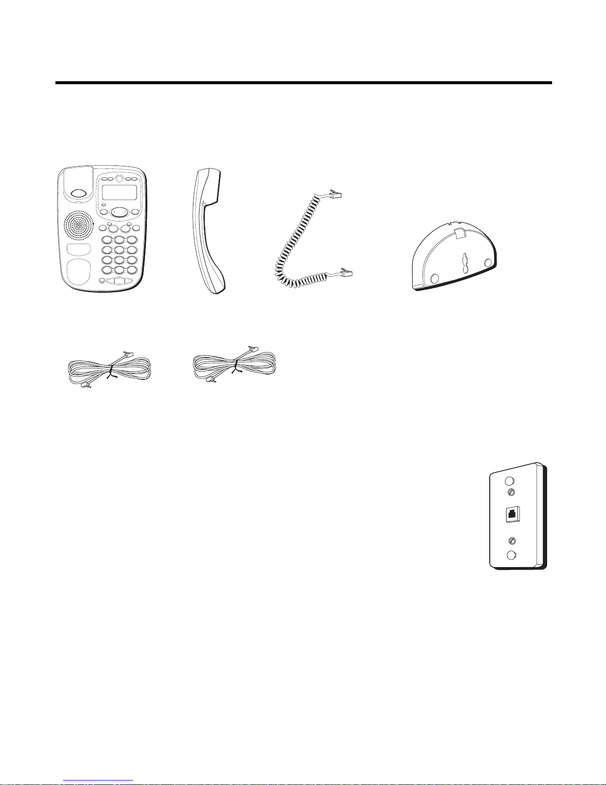
PARTS CHECKLIST
Make sure your package includes the following items:
MODULAR JACK REQUIREMENTS
To properly connect your phone to your telephone lines, you
should identify the type of wall jack(s) you have. You will need
an RJ11C (for a single line) or a RJ14C (for two lines) type
modular phone jack, which might look like the one pictured
here. If you don’t have either modular jack, call your local
phone company to find out how to get one installed.
Base Handset
4-wire telephone
line cord
4-wire telephone
line cord
Handset Cord
Desktop/Wall
Mounting Pedestal
A
B
C
2
D
E
F
3
1
J
K
L
5
M
N
O
6
G
H
I
4
T
U
V
8
W
X
Y
Z
9
P
Q
R
S
7
O
P
E
R
0
#
T
O
N
E
*
2
1
STORE A B C
OPTIONS
ERASE DIAL
REVIEW
CONF HOLD
LINE
VOL
REDIAL FLASH
SPEAKER
PAUSE EXIT
Page 7
7
INSTALLATION & SETUP
CAUTION: Disconnect the phone cord from the wall outlet before
installing or replacing the batteries.
IMPORTANT INSTALLATION INFORMATION
• Never install telephone wiring during a lightning storm.
• Never touch uninsulated telephone wires or terminals, unless the
telephone line has been disconnected at the network interface.
• Use caution when installing or modifying telephone lines.
• Never install telephone jacks in wet locations unless the jack is
specifically designed for wet locations.
•Temporarily disconnect any equipment connected to the phone, such as
faxes, other phones, or modems.
INSTALLING AND REPLACING THE BATTERIES
Your Caller ID phone uses 4 AA-size alkaline batteries for receiving and
storing Caller ID records and for storing the numbers you use for memory
dialing, pulse dialing, and redial.
IMPORTANT: You will have approximately 90 seconds to replace the batteries
before the memories stored are lost. Please read the instructions before
replacing the batteries and have the batteries ready to be inserted beforehand.
IMPORTANT: If you are not going to use the telephone for more than 30
days, remove the batteries because they may leak and damage the unit.
Page 8
8
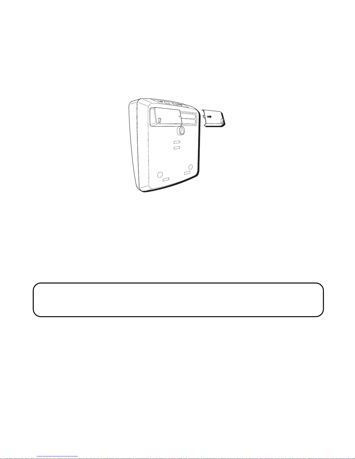
1. Press down and out on the snap tab located on the top of the mounting
bracket. Lift the bracket off.
2. Use a pen or paper clip to loosen the battery cover. Open the battery
compartment by pressing down on the battery cover and sliding it away
from the unit.
3. Insert 4 AA-size alkaline batteries as shown on the diagram in the
battery compartment.
4. Snap the battery compartment door back into place and replace the
mounting bracket.
5. If the line cord was previously connected, re-attach it to the unit and
check your memory locations.
NOTE: If the low battery icon appears in the display, you need to replace the
batteries. It is important that you replace the batteries as soon as possible in
order to maintain Caller ID operation.
Page 9
9
INSTALLATION
DESKTOP INSTALLATION
A coiled handset cord and two straight telephone line cords are packaged
with your unit. Your two-line phone should be placed on a level surface
such as a tabletop or desk.
To attach the desktop pedestal:
• Turn the phone over so that the bottom of the base is facing up and the
thickest end is facing away from you.
• With the rounded end of the wedge pointing downward, insert the tab
on the rounded end of the pedestal into the upper middle slot on the
bottom of the base, then push the pedestal down until the two tabs on
the left and right corners of the pedestal snap (lock) into the two upper
slots on the bottom of the base.
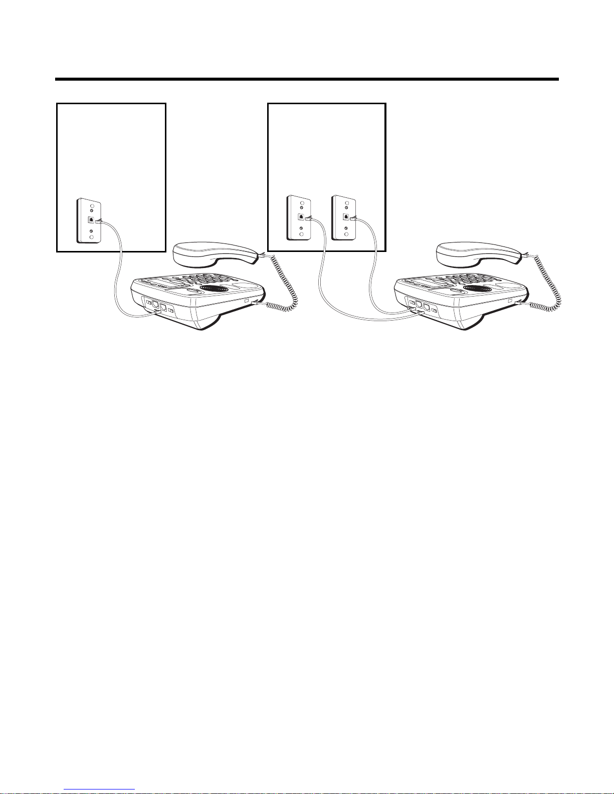
FIGURE 1
FIGURE 2
Two single-line wall
phone jacks
One dual-line
jack or one
single-line wall
phone jack
Page 10

10
To connect LINES 1 + 2:
There are two possible connections.
Refer to Figure 1 if you have one single line (RJ11C) phone jack or one
dual-line (RJ14C) phone jack.
1. Connect one end of either straight telephone line cord to the jack
marked LINE 1+2 on the back of the base.
2. Connect the other end to the single-line or dual-line wall phone jack.
NOTE: If you connect the telephone line cord to the single-line (RJ11C) wall
phone jack, you will only be able to use one telephone line (either LINE 1 or
LINE 2) but not both lines simultaneously.
Refer to Figure 2 if you have two single-line (RJ11C) phone jacks.
1. Connect one end of either straight telephone line cord to the jack
marked LINE 1+2 on the back of the base.
2. Connect one end of the other straight telephone line cord to the jack
marked LINE 2/DATA on the back of the base.
3. Connect the other end of each straight telephone line cord to the two
single line wall phone jack.
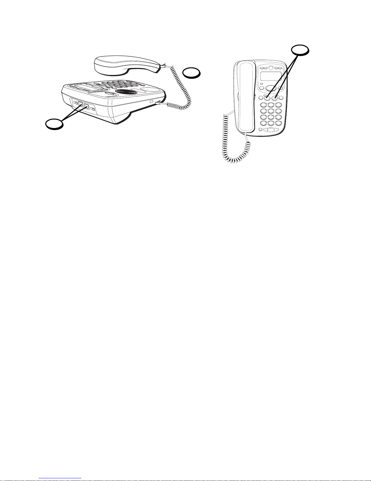
4. Plug one end of the coiled handset cord into the handset and the
opposite end into the base.
5. Set the RINGER LINE 1 and RINGER LINE 2 volume switches located at
the back of the base to the desired loudness.
• = Telephone will not ring.
• = Lo - Sound will be lowest.
• = Hi - Sound will be loudest.
Page 11
11
6. Press the LINE 1 button if the LINE 1 telephone cord is connected.
Otherwise, press LINE 2.
7. The unit is properly installed if you pick up the handset and hear the dial
tone. Otherwise, recheck all installation steps.
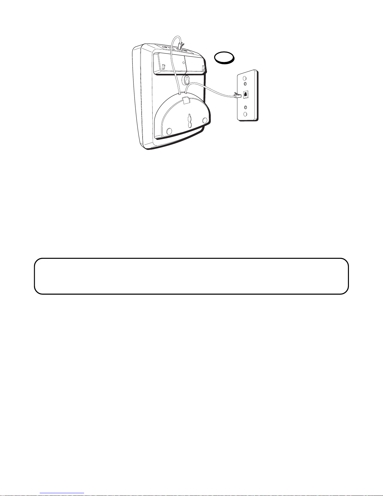
WALL MOUNT INSTALLATION
Your speakerphone can also be mounted on a wall plate (not included).
To attach the wall mounting pedestal:
•Turn the phone over so that the bottom of the base is facing up and the
thickest end is pointing away from you.
• With the rounded end of the pedestal pointing upward, insert the tab on
the end of the pedestal into the lower middle slot on the bottom of the
base, then push the pedestal down until the two tabs on the left and
right corners of the pedestal snap (lock) into the two lower slots on the
bottom of the base.
4
5
A
B
C
2
D
E
F
3
1
J
K
L
5
M
N
O
6
G
H
I
4
T
U
V
8
W
X
Y
Z
9
P
Q
R
S
7
O
P
E
R
0
#
T
O
N
E
*
2
1
STORE A B C
OPTIONS
ERASE DIAL
REVIEW
CONF HOLD
LINE
VOL
REDIAL FLASH
SPEAKER
6
Page 12
12
To connect LINES 1 + 2:
There are two possible connections.
Refer to Figure 1 on page 9 if you have one single line (RJ11C) phone jack
or one dual-line (RJ14C) phone jack.
1. Connect one end of either straight telephone line cord to the jack
marked LINE 1+2 on the back of the base.
2.Connect the other end to the single-line or dual-line wall phone jack.
NOTE: If you connect the telephone line cord to the single-line (RJ11C) wall
phone jack, you will only be able to use one telephone line (either LINE 1 or
LINE 2) but not both lines simultaneously.
Refer to Figure 2 on page 9 if you have two single-line (RJ 11C) phone jacks.
1. Connect one end of either straight telephone line cord to the jack
marked LINE 1+2 on the back of the base.
2. Connect one end of the other straight telephone line cord to the jack
marked LINE 2/DATA on the back of the base.
3. Connect the other end of each straight telephone line cord to the two
single line wall phone jack.
1
Page 13
13
NOTE : If desired, gather the extra telephone line cord together and store
inside the wall mounting bracket.
4. Slip the mounting holes over the wall plate posts and firmly slide the
unit down into place (wall plate not included).
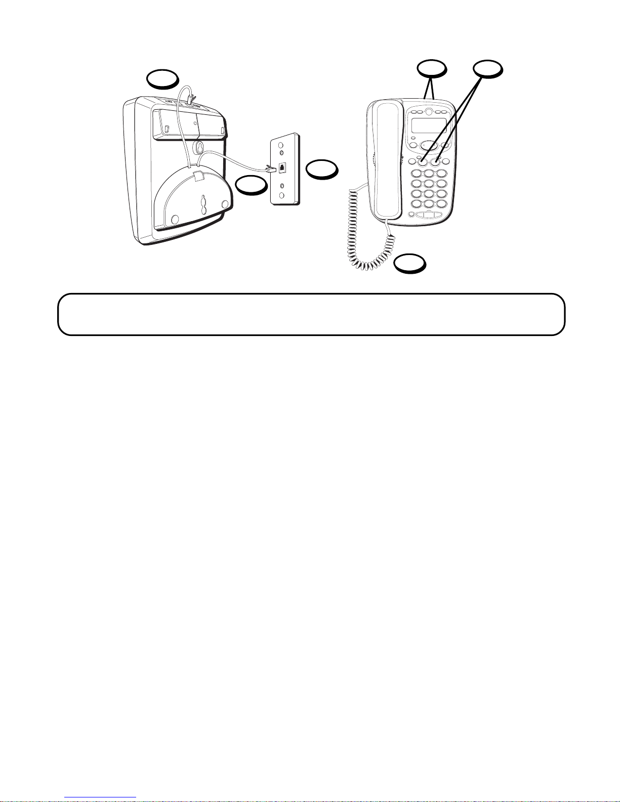
5. Plug one end of the coiled handset cord into the handset and the
opposite end into the base.
6. Set the RINGER LINE 1 and RINGER LINE 2 volume switches located at
the back of the base to the desired loudness.
• = Telephone will not ring.
• = Lo - Sound will be lowest.
• = Hi - Sound will be loudest.
7. P ress the Line 1 button if the Line 1 telephone cord is connected.
Otherwise, press the Line 2 button.
8. The unit is properly installed if you pick up the handset and hear the dial
tone. Otherwise, recheck all installation steps.
A
B
C
2
D
E
F
3
1
J
K
L
5
M
N
O
6
G
H
I
4
T
U
V
8
W
X
Y
Z
9
P
Q
R
S
7
O
P
E
R
0
#
T
O
N
E
*
2
1
STORE A B C
OPTIONS
ERASE DIAL
REVIEW
CONF HOLD
LINE
VOL
REDIAL FLASH
SPEAKER
7
1
4
5
6
3
Page 14
14
DATA PORT
This phone is equipped with a LINE2/DATA jack for you to connect an
auxiliary phone device, such as a fax machine, computer modem,
answering machine, or even a cordless phone. You can install the phone as
described in “Two Lines on a Single Modular Jack”, then you can use the
LINE2/DATA jack to connect your fax machine and receive faxes on the
phone number for line 2.
SETTING UP THE CALLER ID MENU
You should not plug the telephone into the modular jack while setting up
the Caller ID menu.
STORE A B C
OPTIONS
ERASE DIAL
REVIEW
1. Press the OPTIONS button.
OPTIONS
orshows in the display.
2. Press eitherorbutton to scroll through the 7 menu screens, which are:
#1
OPTIONS
or
#2
LOCAL AREA CODE
(default - - -)
#3
10-DIGIT AC'S
(default - - - - - - - -- - - - -)
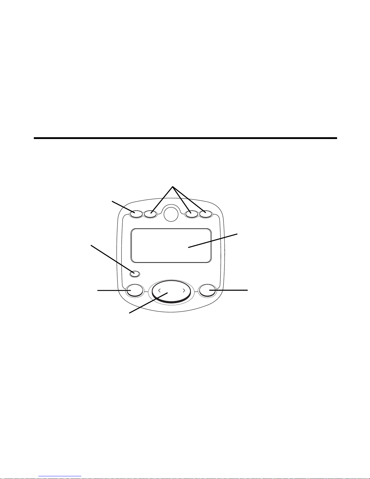
Summary screen
ERASE button DIAL button
OPTIONS button
REVIEW button
STORE button
Quick Dial/Emergency Memory buttons
Page 15

15
#4
CID LANGUAGE
(default is English)
#5
LCD CONTRAST
(default is 3)
#6
T/P DIAL MODE
(default tone)
#7
EXIT SETUP
NOTE: You have 20 seconds following an entry before the phone returns to
the Summary Screen.
SETTING YOUR LOCAL AREA CODE
The telephone uses the programmed area codes to determine the number
format to display when a valid Caller ID signal is received. Numbers that
match the local area code are displayed as seven digits and are used for
dialing back previous numbers. Entering your local area code will also
help you immediately know if the call is local or long distance when
viewing the CID records in the display.
NOTE: If you make a mistake and want to start over, press the ERASE button.
1. Press the OPTIONS button.
OPTIONS
orshows in the display.
2. Press thebutton until
LOCAL AREA CODE
shows in the display.
3. To enter and change an area code, press the OPTIONS button again. The
display shows the current area code stored. The left-most digit or a minus
sign (-) flashes, indicating the unit is ready to accept an area code entry.
4. Use the number keypad to enter the code. The unit automatically moves
to the next digit.
Page 16

16
5. Press to locate the desired digit and re-enter, or press the ERASE
button to clear all three digits and re-enter new digits.
6. Press OPTIONS again to store the area code and return to the
LOCAL
AREA CODE
display.
SETTING REGIONAL AREA CODES FOR 10-DIGIT DIALING
Like the Local Area Code, the telephone uses the programmed area codes
to determine the number format to display when a valid Caller ID signal is
received. Calls that match any of the programmed regional area codes are
displayed as 10 digits. This is helpful in areas that have multiple or
overlapping area codes and require 10-digit dialing.
IMPORTANT: If your area code does not require 10-digit dialing, you can skip
this feature.
1. Press the OPTIONS button.
OPTIONS
orshows in the display.
2. Press button until
10-DIGIT AC'S
shows in the display.
3. Press the OPTION button again.
10-DIGIT AC'S-1
and the first three sets
of regional area codes shows in the display. If you want to edit the
second three sets, press OPTIONS until
10-DIGIT AC'S-2
shows in the
display. Then the second three regional area codes show in the display.
4. Use the button to locate the digit you want to set or change.
5. Use the number keypad (or button) to enter the area code. The unit
automatically advances to the next digit of the regional area code.
6. Press until you locate the desired digit and re-enter the code, or press
the ERASE button to clear all three digits and enter a new area code.
7. P ress OPTIONS again to enter the next three-digit regional area code
and repeat steps 4 to 6 until all the regional area codes are entered.
Page 17

17
NOTE: You can store up to 6 regional area codes.
8. Press OPTIONS again to store the setting and return to the 10-DIGITS
AC’S display.
SETTING THE DISPLAY LANGUAGE
This adjustment changes the Caller ID prompts to be displayed in English,
French, or Spanish.
1. Press the OPTIONS button.
OPTIONS
orappears.
2. Press eitherorbutton until
CID LANGUAGE
appears in the display.
3. Press OPTIONS again to show the current language selected. The default
is English.
4. To change the language, press theorbutton.
5. Press the OPTIONS button again to store the setting and return to the
CID LANGUAGE
display.
SETTING THE CONTRAST
This adjustment allows you to adjust the contrast of the display.
1. Press the OPTIONS button.
OPTIONS
orshows in the display.
2. Press eitherorbutton until
LCD CONTRAST
shows in the display.
3. Press OPTIONS again to show the current contrast setting. There are
five levels of contrast and the default is 3.
4. To decrease the contrast, press the button. To increase contrast,
press the button.
5. Press the OPTIONS button again to store the setting and return to the
LCD CONTRAST
display.
Page 18

18
SETTING THE DIAL MODE
This adjustment allows you to select tone (touch-tone) or pulse (rotary) dialing.
1. Press the OPTIONS button.
OPTIONS
orshows in the display.
2. Press eitherorbutton until
T/P DIAL MODE
shows in the display.
3. Press OPTIONS again to show the current dial mode. The default is Tone.
4. To change the dial mode, press theorbutton. The display will
alternate between the two modes.
5. Press the OPTIONS button again to store the setting and return to the
T/P DIAL MODE
display.
EXITING SET UP
To exit the setup mode after your changes are made, select the
EXIT
SETUP
menu and press the OPTIONS button.
NOTE: The phone will exit Set Up after 20 seconds if no buttons are pressed.
REMINDER: The time and date are programmed automatically when the first
Caller ID record is successfully received after set up.
CALLER ID FEATURES
SUMMARY SCREEN
The Summary Screen shows the current time, date, and number of new
calls to review. It is displayed until any button is pressed.
NOTE: The number of new calls is displayed until all new calls have
been reviewed.
RECEIVING AND STORING CALLS
This unit receives and displays information transmitted by your local
phone company. This information can include the phone number, date, and
time; or the name, phone number, date, and time. The unit can store up to
Page 19

19
75 calls for later review. When the memory is full, a new call automatically
replaces the oldest call in memory.
NEW
appears in the display for calls
received that have not been reviewed. The red NEW CALL indicator blinks,
which means you have received new calls.
REVIEWING CALL RECORDS
•Press theorbutton to view the call records.
•Press the “” button to scroll through the call records from the most
recent to the oldest.
•Press the “”button to scroll through the call records from the oldest to
the newest.
• When all of the records have been viewed,
START/END
appears in
the display.
DELETING CALL RECORDS
•To delete the record shown in the display, press the ERASE button once.
•To delete all records while reviewing, press and hold the ERASE button
for about three seconds.
ERASE ALL?
appears in the display. Press
ERASE again to complete.
DIALING BACK
When reviewing Caller ID records, you can dialback the numbers shown
on the display by pressing the DIAL button.
NOTE: If PICKUP PHONE shows in the display, no other changes to the
number can be made. The information sent from the telephone company is
known to be a valid number for dialing back (used only in very limited areas).
Once you pickup the phone, the number is automatically dialed.
NOTE: Make sure either line button 1 or 2 is pressed, when the handset is
picked-up or the speakerphone is in use.
Page 20

20
IF YOU PROGRAMMED YOUR LOCAL AREA CODE OR REGIONAL AREA
CODE IN THE SETUP MENU
1. Use eitherorbutton to display the number you want to dial.
2. Press the DIAL button.
• If you see a number with seven digits (i.e. 555-1234), then the call is
from within your area code. However, this does not guarantee the call is
a local call.
• If you see a number with 11 digits (i.e. 1-234-555-1234), then the call is
not from within your area code.
NOTE: A timer (10 seconds on-hook and 3 seconds off-hook) located in the
upper right side of the display will start, letting you know how much time is left
until the unit returns to the Summary Screen.
3. If you are at on-hook and “
PICKUP OR ADJ
” displays, you can adjust the
phone number format by pressing the DIAL button. If the phone is offhook and “
ADJUST
” shows in the display, you can adjust the phone
number format by pressing the DIAL button. For example, sometimes a
7-digit local number cannot be dialed because it requires a 10-digit or 11digit format. Press the DIAL button repeatedly to scroll through the 7, 10,
and 11-digit numbers.
7-digits: 7-digit telephone number (i.e. 555-5555)
10-digits: 3-digit area code + 7-digit telephone number (i.e. 425-555-5555)
11-digits: long distance code 1 + 3-digit area code + 7-digit telephone
number (i.e. 1-425-555-5555)
Page 21

21
4. To dial the displayed number, and the phone is on-hook, pick up the
handset or press the SPEAKER button before the timer reaches 0. If the
phone is off-hook, wait until the time reaches 0.
NOW DIALING
shows in
the display and the number is dialed.
NOTE: Make sure either the 1 or 2 line button is pressed.
IF YOU DID NOT PROGRAM YOUR LOCAL AREA CODE AND REGIONAL
AREA CODE IN THE SETUP MENU
1. Use theorbutton to display the number you want to dial. You will
only see 10-digit numbers (i.e. 234- 555-1234).
2. See steps 2 through 4 in the previous section to complete the
dialback process.
CALLER ID DISPLAY MESSAGES
The following special messages indicate the status of a message or the unit:
NO CALLS The caller memory is empty.
UNKNOWN CALLER The incoming call does not have Caller ID service or
their service area is not linked to yours. If
UNKNOWN CALLER
appears along with a calling
number, the name information for that number was
not available.
BLOCKED CALL The caller of the incoming call is registered as
“Private Number” and their Caller ID information
is withheld.
START/END You are at the beginning or the end of the Caller ID
memory log.
Battery power level is low.
Page 22
22
SPEAKERPHONE BASICS
SPEAKERPHONE LOCATION
Your phone features a speakerphone for ease of use and convenience
during a phone conversation. At any time during a conversation, you can
lift the handset to stop using the speakerphone. Likewise, when you are
using the handset, press the SPEAKER button and place the handset in the
cradle to switch to the speakerphone.
For best speakerphone performance, avoid the following:
• Areas with high background noise. (The microphone might pick up
these sounds and prevent the speakerphone from going into the
receiving mode when you finish talking.)
• Surfaces affected by vibration.
•Recessed areas such as in a corner, under a cupboard, or next to a
cabinet, which can generate an echo effect.
A
B
C
2
D
E
F
3
1
J
K
L
5
M
N
O
6
G
H
I
4
T
U
V
8
W
X
Y
Z
9
P
Q
R
S
7
O
P
E
R
0
#
T
O
N
E
*
2
1
STORE A B C
OPTIONS
ERASE DIAL
REVIEW
CONF HOLD
LINE
VOL
REDIAL FLASH
SPEAKER
PAUSE EXIT
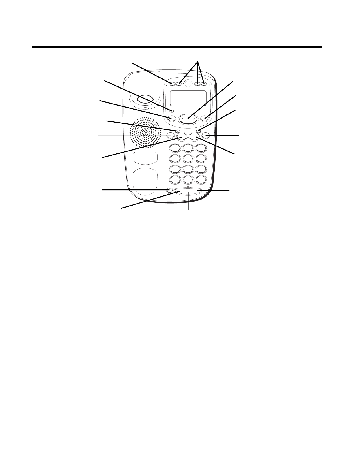
STORE button
OPTIONS button
ERASE button
LINE 1 indicator button
CONF button
LINE 1 button
VOL button
REDIAL/PAUSE button
SPEAKER button
FLASH/EXIT button
LINE 2 indicator button
LINE 2 button
HOLD button
DIAL button
REVIEW button
Quick Dial Memory buttons button
Page 23

23
SPEAKERPHONE USE
Note the following guidelines when using the speakerphone:
• The speakerphone works similar to a two-way radio in that you can only
listen or talk at one time.
• Stay reasonably close to the phone so that you can be clearly heard by
the person to whom you are talking.
•You can adjust the speaker volume by pressing the volume button
continuously or pressing the review button or after pressing the
volume button.
• The speakerphone indicator light comes on when the speakerphone is
in use.
NOTE: Batteries must be installed for the speakerphone to operate.
TELEPHONE BASICS
You can use the telephone by speaking into and listening through the
handset, or by using the Speakerphone feature. For all operations, either
line button 1 or 2 must be pressed. Do not press both buttons down at the
same time.
LINE STATUS INDICATORS
This two-line phone is designed for use at multiple stations. The indicator
light tells you what is happening on each line.
When the indicator light is It Means
OFF The line is not in use.
RedYou have put the line on hold.
Flashing Red You have received an incoming call.
Green You are using the line.
Page 24

24
ANSWERING AND PLACING CALLS
Because this phone has two lines, you must choose a line by pressing the
corresponding line button and use the handset or speakerphone to place
an outgoing call or to answer an incoming call.
USING THE HANDSET
The only difference between using the handset with this phone and other
corded phones is that you must depress a line button after picking up the
handset in order to take the line.
USING THE SPEAKERPHONE
To use the speakerphone feature, press a line button and then press the
SPEAKER button. For more information refer to Speakerphone Basics on
page 22.
RECEIVING A PHONE CALL
1. To answer an incoming call, press the line button next to the flashing
red indicator.
2. Lift the handset or press SPEAKER to answer the call.
3. Replace the handset in the cradle or press the SPEAKER button to
hang up.
MAKING A PHONE CALL
1. Press LINE 1 or LINE 2 button, and lift the handset or press the
SPEAKER button. Wait for a dial tone.
2. Dial the telephone number you want to call.
3. Replace the handset in the cradle, or press the SPEAKER button to
hang up.
Page 25

25
PLACING A CALL WHILE TALKING ON ANOTHER LINE
To place a call without hanging up on the first call:
1. Press the HOLD button to put the first call on hold.
2. Press the available line button to get a dial tone. Press the SPEAKER
button if the speakerphone indicator is off and you are using the
speakerphone.
3. Dial the number you want to call.
RECEIVING A CALL WHILE TALKING ON ANOTHER LINE
When you receive a call while you are talking on another line, you will
hear the phone ring.
1. Press the HOLD button to put the first call on hold.
2. Press the line button next to the flashing red indicator.
3. If the speakerphone indicator is off and you are using the speakerphone,
press the SPEAKER button.
NOTE: You must always put the first call on hold before answering a second call
or you will hang up on the first call. If you want to disconnect from the first call,
don't press the HOLD button (skip step 1) and press the flashing line button.
ADJUSTING THE HANDSET AND SPEAKERPHONE VOLUME
The volume controls for the handset and speakerphone are separate, so
you can adjust one without affecting the other. To adjust the handset
volume, pick up the handset, press the volume button continuously or
press the review button or after pressing the volume button. REC
(handset receiver) or SPK volume level shows in the display. While using
the speakerphone, adjust the speakerphone volume by pressing the
volume button continuously or pressing review button or after pressing
the volume button. Both handset receiver and speakerphone volume level
setting may be saved in the unit's memory.
Page 26

26
ADDITIONAL TELEPHONE FEATURES
REDIAL
You may redial the last number you called by pressing the REDIAL button
after you hear a dial tone.
NOTE: The redial feature holds the last number (up to 32 digits) that you
dialed in memory. If you pressed any other numbers after dialing the phone
number (for example, when accessing a voice-menu system) then those
numbers are dialed instead of the last phone number you dialed.
If you get a busy signal, press REDIAL again without hanging up.
HOLD
HOLD allows you to suspend the active line(s) and replace the handset in
the cradle without hanging up, then resume the conversation on the same
phone or from a different phone connected to the same line.
1. Press the HOLD button to place a call on hold (the line indicator is red).
2. Press the line button and pickup the handset or press the SPEAKER
button to resume the conversation.
CONFERENCE CALLS
You can use the Conference Call feature when you have calls on both lines
and want to have a three-way conversation.
To connect and conference:
1. Press the line button for the line you want to use, then call the first party.
2. Press the HOLD button to put the first party on hold.
Page 27

27
3. Call the second party, or receive a call, on the other line, then press the
CONFERENCE button.
4. Begin speaking to both parties.
To disconnect one of the parties:
Press the line button of the person you want to continue talking to, and the
other party will automatically be disconnected.
To disconnect both parties:
Hang up the handset, or press SPEAKER.
NOTE: If you have two lines on hold, and you want to conference with both
parties, simply press the CONFERENCE button and pick up the handset or
press SPEAKER button.
NOTE: To put both parties on hold, press the HOLD button.
NOTE: To speak to one party individually, press the HOLD button, then press
the line of the party to whom you want to speak (the second party remains on
hold.) If the speakerphone indicator is off and you are using the speakerphone,
press the SPEAKER button to continue the conversation on the speakerphone.
FLASH
Press FLASH to activate special features of your telephone network, such
as call transfer, or special services from your local telephone company,
such as call waiting.
NOTE: "F" shows in the display when the FLASH button is pressed.
Page 28

28
TEMPORARY TONE DIALING
If you have pulse (rotary) service and want to access customer calling services
(such as telebanking and long distance services) that require tone dialing, you
can use this feature to temporarily change from pulse to tone service.
After dialing the telephone number and connecting to the customer
calling service,
1. Press and release the TONE (*) button.
2. When you hang up, the telephone automatically returns to pulse
dialing mode.
TIP: Temporary Tone can also be used while storing numbers in memory by
pressing TONE (*) at the necessary point in the storage sequence.
MEMORY
You may store information in any of the following memory locations: 1 to 9, A,
B, and C keys. See “Storing a Pause in Memory” and “Temporary Tone
Dialing.”
STORING A NAME AND NUMBER IN MEMORY
1. Press the STORE button.
LOCATION?
shows in the display.
2. Press the desired memory location (1 through 9, A, B, or C).
NOTE: You may select memory locations by pressing or to scroll through
the memory locations or press the 1 - 9, A, B, or C buttons.
3. Press the STORE button again to confirm the memory location.
NOTE: If necessary, to erase existing memories, or if you make a mistake, use
the ERASE button.
4. Use the number keys to enter the telephone number (up to 32 digits)
and press the STORE button to save. (The unit will not dial a phone
number in this mode.) The cursor automatically moves to the text line
for name entry.
Page 29

29
5. Use the number keys to enter the name of the person associated with
the telephone number you just entered. More than one letter is stored in
each of the number keys.
For example, to enter the name BILL SMITH, press the 2 key twice for the
letter B. Press the 4 key 3 times for the letter I. Press the 5 key 3 times for
the letter L.
NOTE: The flashing cursor automatically moves to the next position or you
may press the or button to move the cursor to the next position.
Press the 5 key 3 times for the second letter L. Press the arrow key () two
times to insert a space, and press the 7 key 4 times for the letter S. Press
the 6 key once for the letter M. Press the 4 key 3 times for the letter I. Press
the 8 key for the letter T. Press the 4 key twice for the letter H.
6. Press the STORE button to save the name.
7. To enter another name and number in a different memory location,
return to step 1 and repeat the process.
CHANGING A STORED NUMBER
Repeat the storage sequence under Storing A Name and Number in
Memory, and use the ERASE button to delete the old number before
entering the new number.
ERASING A STORED NUMBER
1. Press the STORE button.
2. Press the memory location (A, B, C, 1 - 9) to be erased.
3. Press the ERASE button.
Page 30

30
COPYING CALLER ID MEMORIES TO USER MEMORY
1. Press the or button to view the caller number and name you want
to copy.
2. Press the STORE button.
3. Press 1-9, A, B, or C for the memory location. The memory location flashes
in the display if there is a record occupying that memory location.
NOTE: You may select a different memory location by pressing or to scroll
through the memories or press A, B, or C or 1 - 9.
4. Press the STORE button to enter the edit mode, and then press the
STORE button again to edit the name.
5. Press the STORE button to confirm and save, and wait for three seconds
to exit.
NOTE: If the name you want to enter is longer than 12 characters, only the
first 12 characters will be copied into memory.
COPYING REDIAL NUMBERS TO MEMORY
1. Press the REDIAL button while the phone is on-hook. The display shows
"
PICKUP PHONE
."
2. Press the STORE button.
3. Press 1-9, A, B, or C for the memory location. The cursor flashes in the
display and you may enter the caller's name.
4. Press the STORE button to confirm and save, and wait for three seconds
to exit.
NOTE: If you want to edit the number, press the STORE button within three
seconds to enter the edit mode.
Page 31

31
DIALING A NUMBER STORED IN MEMORY WHILE ON-HOOK
1. Press a line button.
2. To select a memory, press A, B, or C or 1 - 9. The number in that
memory location displays.
NOTE: You may select a different memory location by pressing or to scroll
through the memories or press A, B, or C or 1 - 9.
3. Press the SPEAKER button, or pick up the handset to dial the displayed
number.
DIALING A NUMBER STORED IN MEMORY
1. Press a line button, and lift the handset, or press the SPEAKER button.
2. Press a memory location then press A, B, or C or DIAL and 1 - 9.
IMPORTANT: If you make test calls to emergency numbers, remain on the
line and explain the reason for the call. Also, make test calls in off-peak hours,
such as early morning or late evening.
CHAIN DIALING
Chain dialing allows you to dial a sequence of stored numbers from
separate memory locations.
For example Memory location
Local access number A
Long distance company Authorization code ID B
Long distance phone number Memory 1
Page 32

32
1. S elect the line you want to use by pressing the corresponding line button.
2. Lift the handset, or press SPEAKER for speakerphone
3. Press Memory button A.
4. Press Memory button B.
5. Press the DIAL button and the 1 key.
STORING A PAUSE IN MEMORY
The REDIAL button has dual functionality and becomes a pause button
when the STORE button is pressed first. It is valid only when storing a
number into memory locations. Use the PAUSE (REDIAL) button to insert a
pause when a delay is needed in an automatic dialing sequence. For
example, when you must dial a 9 to get an outside line or when you enter
codes to access your long distance company.
You may need to adjust the length of the pause duration. It can be
adjusted from 1 to 9 seconds in length. The default setting is 4 seconds.
1. Press the STORE button.
2. Press the PAUSE (REDIAL) button. The current pause time displays.
3. Press the or button to scroll the pause time, or press the 1 to 9 key
for one second to nine seconds respectively (i.e.; 1 = one second, 2 =
two seconds).
4. Press the STORE button to save.
PRE-DIAL
Use the pre-dial feature to enter a telephone number and automatically
dial out without lifting the handset or pressing the SPEAKER button.
1. Enter the telephone number.
2. Lift the handset or press the SPEAKER button.
NOTE: Press FLASH button to delete the pre-dial number.
Page 33

33
TROUBLESHOOTING TIPS
NO DIAL TONE
•You must press a line button to get a dial tone.
• Check all cabling to make sure that all connections are secure and not
damaged.
• Check hook switch: Does it fully extend when handset is lifted from
cradle?
NO DISPLAY
•Replace batteries.
• Check for proper battery installation.
NO INFORMATION IS SHOWN AFTER THE PHONE RINGS
• Did you order Caller ID service from your local telephone company? This
unit requires that you subscribe to Caller ID service in order to work.
• Be sure to wait until the second ring before answering.
PHONE DIALS IN PULSE WITH TONE SERVICE
• Make sure T/P DIAL MODE in the setup menu is set to TONE DIAL.
PHONE WON'T DIAL OUT WITH PULSE SERVICE
• Make sure T/P DIAL MODE in the setup menu is set to PULSE DIAL.
Page 34

34
PHONE DOES NOT RING
• Is the ringer switch in the OFF position?
• Are you using too many phones on one line? (The total REN of all phones
on the same line should not be greater than the maximum REN for your
calling area. See paragraph 1 of the Equipment Approval Information
section on page 2 of this User's Guide for more information).
•See No Dial Tone.
INCOMING AND OUTGOING VOICE VOLUME LOW
• Are other phones off hook at same time? If so, this is normal condition
as volume drops when additional phones are used at once.
• Check the handset or speaker volume.
TELEPHONE CONTINUES TO RING AFTER HANDSET IS PICKED UP OR
SPEAKER BUTTON IS PRESSED
•You must press the line number to answer a call.
MEMORY DIALING
• Make sure you entered the numbers correctly into memory.
Page 35

35
GENERAL PRODUCT CARE
To keep your phone working and looking good, follow these guidelines:
•Avoid putting it near heating appliances and devices that generate
electrical noise (for example, motors or fluorescent lamps).
• DO NOT expose to direct sunlight or moisture.
•Avoid dropping and other rough treatment to the unit.
• Clean with a soft cloth.
• Never use a strong cleaning agent or abrasive powder because this will
damage the finish.
•Retain the original packaging in case you need to ship it at a later date.
SERVICE
This product may be serviced only by the manufacturer or its authorized
service agents. Changes or modifications not expressly approved by
ATLINKS USA, Inc. could void the user’s authority to operate this product.
For instructions on how to obtain service, refer to the warranty included in
this guide or call customer service at 1-800-448-0329.
Or refer inquiries to:
ATLINKS USA, Inc.
Manager, Consumer Relations
P O Box 1976
Indianapolis, IN 46206
Attach your sales receipt to the booklet for future reference or jot down the
date this product was purchased or received as a gift. This information will
be valuable if service should be required during the warranty period.
Purchase date ________________________________________________
Name of store ________________________________________________
Page 36

36
INDEX
A
Additional Telephone Features 26
Adjusting the Handset and Speaker-
phone Volume 25
Answering and Placing Calls 24
B
Before You Begin 6
C
Caller ID Display Messages 21
Caller ID Features 18
Chain Dialing 31
Changing a Stored Number 29
Conference Calls 26
Copying Caller ID Memories to User
Memory 30
Copying Redial Numbers to Memory 30
D
Deleting Call Records 19
Desktop Installation 9
Dialing a Number Stored in Memory 31
Dialing a Number Stored in Memory
While On-hook 31
Dialing Back 19
E
Equipment Approval Information 2
Erasing a Stored Number 29
Exiting Set Up 18
F
Flash 27
G
General Product Care 35
H
Hearing Aid Compatibility 2
Hold 26
I
If You Did Not Program Your Local Area
Code and Regional Area Code in
the Setup Menu 21
If You Programmed Your Local Area Code
or Regional Area Code in the Setup
Menu 20
Important Installation Information 7
Installation 9
Installation & Setup 7
Installing and Replacing the Batteries 7
Interference Information 2
Introduction 5
L
Limited Warranty 38
Line Status Indicators 23
M
Making a Phone Call 24
Memory 28
Modular Jack Requirements 6
P
Parts Checklist 6
Placing a Call While Talking on Another
Line 25
Pre-Dial 32
Page 37

37
R
Receiving A Call While Talking on
Another Line 25
Receiving a Phone Call 24
Receiving and Storing Calls 18
Redial 26
Reviewing Call Records 19
S
Service 35
Setting Regional Area Codes for 10-Digit
Dialing 16
Setting the Contrast 17
Setting the Dial Mode 18
Setting the Display Language 17
Setting Up the Caller ID Menu 14
Setting Your Local Area Code 15
Short Glossary of Terminology Used in
this Manual 5
Speakerphone Basics 22
Speakerphone Location 22
Speakerphone Use 23
Storing a Name and Number in
Memory 28
Storing a Pause in Memory 32
Summary Screen 18
T
Telephone Basics 23
Temporary Tone Dialing 28
Troubleshooting Tips 33
U
Using the Handset 24
Using the Speakerphone 24
W
Wall Mount Installation 11
Page 38

Model 29481
15809850 (Rev. 1 E/S)
02-29
Printed in China
ATLINKS USA, Inc.
101 West 103rd Street
Indianapolis, IN 46290
© 2002 ATLINKS USA, Inc.
Trademark(s) ® Registered
Marca(s) Registrada(s)
LIMITED WARRANTY
What your warranty covers:
• Defects in materials or workmanship.
For how long after your purchase:
• One year, from date of purchase.
(The warranty period for rental units begins with the first rental or 45 days from date of shipment to the rental firm, whichever comes first.)
What we will do:
•Provide you with a new or, at our option, a refurbished unit. The exchange unit is under warranty for the remainder of the original product’s
warranty period.
How you get service:
•Properly pack your unit. Include any cables, etc., which were originally provided with the product. We recommend using the original carton
and packing materials.
•”Proof of purchase in the form of a bill of sale or receipted invoice which is evidence that the product is within the warranty period, must be
presented to obtain warranty service.” For rental firms, proof of first rental is also required. Also print your name and address and a
description of the defect. Send via standard UPS or its equivalent to:
ATLINKS USA, Inc.
c/o Thomson multimedia Inc.
11721 B Alameda Ave.
Socorro, Texas 79927
•Pay any charges billed to you by the Exchange Center for service not covered by the warranty.
• Insure your shipment for loss or damage. ATLINKS accepts no liability in case of damage or loss.
•A new or refurbished unit will be shipped to you freight prepaid.
What your warranty
does not
cover:
• Customer instruction. (Your Owner’s Manual provides information regarding operating instructions and user controls. Any additional
information, should be obtained from your dealer.)
• Installation and setup service adjustments.
• Batteries.
• Damage from misuse or neglect.
•Products which have been modified or incorporated into other products.
•Products purchased or serviced outside the USA.
• Acts of nature, such as but not limited to lightning damage.
Product Registration:
• Please complete and mail the Product Registration Card packed with your unit. It will make it easier to contact you should it ever be
necessary. The return of the card is not required for warranty coverage.
Limitation of Warranty:
• THE WARRANTY STATED ABOVE IS THE ONLY WARRANTY APPLICABLE TO THIS PRODUCT. ALL OTHER WARRANTIES, EXPRESS OR IMPLIED
(INCLUDING ALL IMPLIED WARRANTIES OF MERCHANTABILITY OR FITNESS FOR A PARTICULAR PURPOSE) ARE HEREBY DISCLAIMED. NO
VERBAL OR WRITTEN INFORMATION GIVEN BY ATLINKS USA, INC., ITS AGENTS, OR EMPLOYEES SHALL CREATE A GUARANTY OR IN ANY
WAY INCREASE THE SCOPE OF THIS WARRANTY.
• REPAIR OR REPLACEMENT AS PROVIDED UNDER THIS WARRANTY IS THE EXCLUSIVE REMEDY OF THE CONSUMER. ATLINKS USA, INC.
SHALL NOT BE LIABLE FOR INCIDENTAL OR CONSEQUENTIAL DAMAGES RESULTING FROM THE USE OF THIS PRODUCT OR ARISING OUT
OF ANY BREACH OF ANY EXPRESS OR IMPLIED WARRANTY ON THIS PRODUCT. THIS DISCLAIMER OF WARRANTIES AND LIMITED
WARRANTY ARE GOVERNED BY THE LAWS OF THE STATE OF INDIANA. EXCEPT TO THE EXTENT PROHIBITED BY APPLICABLE LAW, ANY
IMPLIED WARRANTY OF MERCHANTABILITY OR FITNESS FOR A PARTICULAR PURPOSE ON THIS PRODUCT IS LIMITED TO THE APPLICABLE
WARRANTY PERIOD SET FORTH ABOVE.
How state law relates to this warranty:
•Some states do not allow the exclusion nor limitation of incidental or consequential damages, or limitations on how long an implied
warranty lasts so the above limitations or exclusions may not apply to you.
• This warranty gives you specific legal rights, and you also may have other rights that vary from state to state.
If you purchased your product outside the USA:
• This warranty does not apply. Contact your dealer for warranty information.
Page 39

1
29481
Creamos cosas buenas para la vida.
Teléfono con Altavoz de Dos Líneas
e Identificador de Llamadas con
Memoria para 12 Números
Guía del Usuario
Page 40

2
INFORMACIÓN SOBRE LA APROBACIÓN DE EQUIPO
El equipo de su teléfono esta aprobado para la conexión con la red Telefónica Pública (Public Switched Telephone
Network) y cumple con los requisitos establecidos en las secciones 15 y 68 de las Reglas y Regulaciones de la FCC y con
los Requerimientos Técnicos para Equipos de Terminales Telefónicas (Technical Requirements for Telephone Terminal
Equipment), publicado por ACTA.
1. Notificación a la Compañía Telefónica Local
En la parte de abajo de este equipo hay una etiqueta que indica, entre otra información, el número de US y el
Número de Equivalencia de Timbres (REN) para este equipo. Usted debe, cuando sea requerido, proveer esta
información a su compañía telefónica.
El REN es útil para determinar el número total de artefactos que Ud. puede conectar a su línea telefónica, todavía
asegurando que todos estos artefactos sonarán cuando se llame su número telefónico. En la mayoría de las áreas
(pero no en todas), el total de los números REN de todos los artefactos conectados a una línea no debe exceder 5.
Para estar seguro del número total de artefactos que Ud. pueda conectar a su línea (determinado por el REN), Ud.
deberá ponerse en contacto con su compañía telefónica local.
NOTAS:
• No se puede usar este equipo con un teléfono de previo pago proveído por la compañía telefónica.
• Las líneas compartidas son sujetas a las tarifas del estado, y por eso, es posible que Ud. no pueda usar su propio
equipo telefónico si Ud. estuviera compartiendo la misma línea telefónica con otros abonados.
•Se debe notificar la compañía telefónica cuando se desconecte permanentemente su teléfono de la línea.
2. Derechos de la Compañía Telefónica
Si su equipo causase algún problema en su línea que pudiera dañar la red telefónica, la compañía telefónica siempre
que sea posible le avisará de la posible interrupción temporal de su servicio. En caso que la compañía no pudiera
avisarle de antemano y hubiera necesidad de tomar tal acción, la compañía telefónica podrá interrumpir su servicio
inmediatemente. En caso de tal interrupción telefónica temporal la compañía debe : (1) darle aviso al momento de tal
interrupción temporal de servico, (2) concederle a Ud. la oportunidad de corregir la situación, (3) informarle a Ud. de
sus derechos de presentar una questa a la Comisión de acuerdo con los procedimientos dictados en la Subparte E de
la Parte 68 de las Regulaciones y Reglas de la FCC.
La compañía telefónica puede hacer los cambios en sus instalaciones de comunicación, en equipos, en sus
funcionamientos o procedimientos que digne necesarios para el manejo de sus negocios y que no sean
incompatibles con las Reglas y Regulaciones de l a FCC. Si estos cambios pudieran alterar el uso o el funcionamiento
de su equipo telefónico, la compañía telefónica deberá darle aviso adecuado en escrito para que Ud. goce de un
servico ininterrumpido.
INFORMACIÓN DE INTERFERENCIAS
Este artefacto cumple con la Parte 15 de las Reglas de la FCC. Su funcionamiento es sujeto a las dos condiciones
siguientes: (l) Este artefacto no puede causar interferencia dañosa, y (2) Este artefacto debe aceptar cualquier interferencia
recibida, incluyendo interferencia que puede causar un funcionamiento no deseado.
Este equipo ha sido probado y cumple con los límites para un artefacto digital de la Clase B, de conformidad con la Parte
15 de las Reglas de la FCC. Estos límites han sido diseñados para proporcionar una protección razonable contra una
interferencia dañosa que pueda existir en una instalación doméstica.
Este equipo genera, usa y puede radiar la energía de frecuencia de una radio y, si no fuera instalado y usado de acuerdo
con las instrucciones, puede causar interferencia dañosa a las transmisiones radiales. Sin embargo, no hay garantía que
la interferencia no ocurrirá en una instalación en particular.
Si este equipo causa en efecto una interferencia dañosa a la recepción de la radio o de la televisión, lo cual puede ser
determinado apagando y prendiendo el equipo, le animamos a Ud. de tratar de corregir la interferencia por medio de una
(o más) de las sugerencias siguientes:
• Cambie la posición o la ubicación de la antena (quiere decir la antena de la radio o de la televisión que está
recibiendo la interferencia).
• Cambie la posición o cambie la ubicación y aumente la distancia entre el equipo de telecomunicaciones y la
antena receptora de la radio o de la televisión que está recibiendo la interferencia.
• Conecte el equipo de telecomunicaciones a una toma en un circuito diferente del circuito al cual la antena
receptora esté conectada.
Si estas medidas no eliminan la interferencia, favor de consultar a su distribuidor o a un técnico de radio/televi
sión experto por otras sugerencias. También, la Comisión Federal de Comunicaciones (FCC) ha preparado un folleto muy
útil, “How To Identify and Resolve Radio/TV Interference Problems” (“Como Identificar y Resolver Problemas de
Interferencia de Radio/Televisión”). Este folleto se puede obtener del U.S. Goverment Printing Office, Washington, D.C.
20402. Favor de especificar el número 004-000-00345-4 cuando haga su pedido.
COMPATIBILIDAD CON AUDÍFONOS
Se juzga que este teléfono es compatible con audífonos, en base a las normas de la FCC.
El número de la US está ubicado en el fondo de la base
El numero REN esta ubicado en el fondo de la base
Page 41

3
VEA ADVERTENCIA EN LA PARTE POSTERIOR/BASE DEL PRODUCTO.
RIESGO DE SACUDIDA
ELÉCTRICA NO ABRA
ADVERTENCIA: PARA PREVENIR
EL RIESGO DE UNFUEGO O DE UNA
SACUDIDA ELECTRICA, NO EXPONGA
ESTE APARATO A LA LLUVIA O A LA
HUMEDAD.
EL RELÁMPAGO Y LA
PUNTA DE FLECHA
DENTRO DEL TRIÁNGULO
ES UNA SEÑAL DE
ADVERTENCIA,
ALERTÁNDOLE A UD. DE
QUE HAY "VOLTAJE
PELIGROSO" DENTRO DEL
PRODUCTO.
CUIDADO: PARA REDUCIR
EL RIESGO DE UNA SACUDIDA
ELÉCTRICA, NO QUITE LA
CUBIERTA (O PARTE
POSTERIOR) NO USE PARTES
DE REPUESTO DENTRO.
CONSULTE A ALGUNA
PERSONA CALIFICADA DEL
SERVICIO DE REPARACIONES.
EL SIGNO DE
EXCLAMACIÓN DENTRO
DEL TRIÁNGULO ES UNA
SEÑAL DE
ADVERTENCIA,
ALTERTÁNDOLE A UD. DE
QUE EL PRODUCTO, TRAE
INCLUCIDO,
INSTRUCTIONES MUY
IMPORTANTES.
AT TENTION:
TABLA DE CONTENIDO
INFORMACIÓN SOBRE LA APROBACIÓN DE EQUIPO ... 2
INFORMACIÓN DE INTERFERENCIAS ..................... 2
COMPATIBILIDAD CON AUDÍFONOS ..................... 2
TABLA DE CONTENIDO .................................... 3
INTRODUCCIÓN .............................................. 5
GLOSARIO DE T ÉRMINOS UTILIZADOS EN ESTE
MANUAL ...................................... 5
ANTES DE COMENZAR .................................... 6
LISTA DE PARTES ....................................... 6
REQUISITOS DE CONEXIÓN .......................... 6
INSTALACIÓN Y PROGRAMACIÓN ........................ 7
INFORMACIÓN IMPORTANTE PARA
LA INSTALACIÓN ............................ 7
PARA INSTALAR O CAMBIAR LAS BATERÍAS ..... 7
INSTALACIÓN ................................................. 9
INSTALACIÓN SOBRE SUPERFICIE PLANA ......... 9
INSTALACIÓN SOBRE PARED ........................11
TERMINAL DE DATOS ................................ 14
PARA PROGRAMAR EL MENÚ DEL
IDENTIFICADOR DE LLAMADAS (CALLER ID).... 14
PARA PROGRAMAR SU CLAVE DE ÁREA
LOCAL ....................................... 15
PARA PROGRAMAR SU CLAVE DE ÁREA
REGIONAL PARA MARCAR CON
NÚMEROS DE 10-DÍGITOS ............ 16
PARA PROGRAMAR EL IDIOMA EN LA
PANTALLA .................................. 17
PARA PROGRAMAR EL CONTRASTE ............. 17
PARA PROGRAMAR LA MODALIDAD PARA
MARCAR .................................... 18
PARA SALIR DE PROGRAMACIÓN ................ 18
FUNCIONES DEL IDENTIFICADOR DE LLAMADAS .... 18
PANTALLA SUMARIO ................................ 18
PARA RECIBIR Y ALMACENAR LLAMADAS ...... 19
PARA REVISAR LOS ARCHIVOS
DE LLAMADAS ......................................... 19
PARA BORRAR ARCHIVOS DE LLAMADAS ...... 19
PARA V OLVER A MARCAR (CONTESTANDO
UNA
LLAMADA)............................ 19
SI USTED PROGRAMÓ SU CLAVE DE
ÁREA LOCAL O REGIONAL EN EL MENÚ
DE
PROGRAMACIÓN ...................... 20
SI USTED NO PROGRAMÓ SU CLAVE DE
ÁREA LOCAL Y SU CLAVE DE ÁREA
REGIONAL EN EL MENÚ DE
PROGRAMACIÓN .......................... 21
MENSAJES EN LA PANTALLA DEL
IDENTIFICADOR DE LLAMADAS ...................... 21
FUNCIONES BÁSICAS DEL ALTAV OZ .................. 22
LOCALIZACIÓN DEL ALTAVOZ ...................... 22
USO DEL ALTAVO Z ................................... 23
FUNCIONES BÁSICAS DEL T ELÉFONO ................ 23
INDICADORES DEL ESTADO DE LAS LÍNEAS .... 23
PARA CONTESTAR Y HACER LLAMADAS ........ 24
PARA UTILIZAR EL AURICULAR ................... 24
PARA UTILIZAR EL ALTAVO Z ....................... 24
PARA RECIBIR UNA LLAMADA .................... 24
PARA HACER UNA LLAMADA ..................... 24
PARA HACER UNA LLAMADA MIENTRAS
USTED ESTÁ EN OTRA LÍNEA .......... 24
PARA RECIBIR UNA LLAMADA MIENTRAS
USTED ESTÁ EN OTRA LÍNEA .......... 25
PARA AJUSTAR EL VOLUMEN DEL
AURICULAR Y DEL A LTAVOZ ........................ 25
FUNCIONES ADICIONALES DEL T ELÉFONO .......... 26
PARA V OLVER A MARCAR (“REDIAL”)....... 26
EN ESPERA ............................................ 26
LLAMADAS EN CONFERENCIA ..................... 26
SERVICIOS ESPECIALES (“FLASH”) .......... 27
TONO T EMPORARIO PARA MARCAR ............. 28
Page 42

4
MEMORIA ................................................... 28
PARA ALMACENAR UN NOMBRE/ NÚMERO
EN LA MEMORIA ...................................... 28
PARA CAMBIAR UN NÚMERO ALMACENADO ... 29
PARA BORRAR UN NÚMERO ALMACENADO ... 29
PARA COPIAR LAS MEMORIAS DEL
IDENTIFICADOR DE LLAMADAS A LA
MEMORIA DEL USUARIO ............... 30
PARA COPIAR NÚMEROS A MARCAR
NUEVAMENTE EN LA MEMORIA ...... 30
PARA MARCAR UN NÚMERO ALMACENADO
EN LA MEMORIA MIENTRAS EL
TELÉFONO ESTÁ COLGADO ............ 31
PARA MARCAR UN NÚMERO ALMACENADO
EN
LA MEMORIA .......................... 31
PARA MARCAR EN CADENA ....................... 31
PARA ALMACENAR UNA PAUSA EN LA
MEMORIA .................................. 32
PARA ANTES DE V OLVER A MARCAR
(PRE-DIAL) ............................................ 32
SOLUCIÓN DE PROBLEMAS ............................ 33
CUIDADO GENERAL DEL PRODUCTO ................. 35
CÓMO OBTENER SERVICIOS DE MANTENIMIENTO35
ÍNDICE ....................................................... 36
GARANTÍA LIMITADA .................................... 38
Page 43

5
INTRODUCCIÓN
CUIDADO: Cuando utilice equipo telefónico, hay instrucciones
básicas de seguridad que siempre deben seguirse. Refiérase a la guía
de INSTRUCCIONES DE SEGURIDAD IMPORTANTES provista con
este producto y guárdela para referencia futura.
Su teléfono con Identificador de Llamadas almacena y muestra
información específica, provista por su compañía telefónica local, a
suscriptores de servicios de identificación como el Identificador de
Llamadas o servicios similares. Usted debe suscribirse a alguno de estos
servicios para poder utilizar este aparato.
Su Identificador de Llamadas (Caller ID) le permite:
• Identificar a la persona que llama antes de que usted conteste el teléfono.
•Ver la hora y fecha de cada llamada entrante.
• Grabar hasta 75 mensajes del Identificador de Llamadas (Caller ID) en
secuencia.
IMPORTANTE: Para poder utilizar todas las funciones de este aparato, usted
debe suscribirse al Servicio de Identificador de Llamadas de Nombre/Número
que le es disponible a través de su compañía telefónica local.
GLOSARIO DE TÉRMINOS UTILIZADOS EN ESTE MANUAL
Gancho para Colgar (Hook switch): Parte del teléfono que rebota para
activar la línea telefónica cuando el auricular se levanta de la base.
Indicador de Línea (Line Indicator): La luz localizada junto a cada botón de
línea; muestra el estado actual de cada línea.
Descolgado (Off-hook): Un término que se utiliza para describir el teléfono en
la modalidad activa cuando el auricular está fuera de la base o cuando un
botón de la línea está oprimido junto con el botón del altavoz (“SPEAKER”).
Colgado (On-hook): Un término que se utiliza para describir el teléfono en
modalidad inactiva.
Page 44

6
REQUISITOS DE CONEXIÓN
Para conectar adecuadamente su teléfono a las líneas
telefónicas, usted debe identificar el tipo de enchufe(s) de
pared que usted tiene. Usted necesitará un enchufe tipo
modular RJ11C (para línea sencilla) o un RJ14C (para dos
líneas), que puede parecerse al enchufe ilustrado aquí. Si
usted no tiene ninguno de estos enchufes, usted puede
llamar a su compañía telefónica local para enterarse de cómo
puede obtener que se le instale uno.
ANTES DE COMENZAR
LISTA DE PARTES
Asegúrese de que su paquete incluye los siguientes artículos:
Base
Pedestal para Montaje
sobre Superficie
Plana/ Pared
A
B
C
2
D
E
F
3
1
J
K
L
5
M
N
O
6
G
H
I
4
T
U
V
8
W
X
Y
Z
9
P
Q
R
S
7
O
P
E
R
0
#
T
O
N
E
*
2
1
STORE A B C
OPTIONS
ERASE DIAL
REVIEW
CONF HOLD
LINE
VOL
REDIAL FLASH
SPEAKER
PAUSE EXIT
Auricular
Cable de línea de 4
alambres
Cable del auricular
Cable de línea de 4
alambres
Page 45

7
INSTALACIÓN Y PROGRAMACIÓN
CUIDADO: Desconecte el cable telefónico del enchufe de pared antes
de instalar o cambiar las baterías.
INFORMACIÓN IMPORTANTE PARA LA INSTALACIÓN
• Nunca instale cableado telefónico durante una tormenta de relámpagos.
• Nunca toque cables o terminales no aislados, a menos que la línea
telefónica haya sido desconectada en la interfaz de la red.
• Utilice precaución cuando instale o modifique líneas telefónicas.
• Nunca instale enchufes telefónicos en localizaciones mojadas, a menos
que el enchufe esté específicamente diseñado para mojarse.
• Desconecte temporalmente cualquier equipo que esté conectado al
teléfono, como fax, otros teléfonos, o módems.
PARA INSTALAR O CAMBIAR LAS BATERÍAS
Su teléfono con Identificador de Llamadas utiliza cuatro baterías alcalinas
tamaño AA para recibir y almacenar archivos del Identificador de
Llamadas y para almacenar los números que usted utiliza para marcar por
memoria, marcar por modalidad rotatoria, y para volver a marcar.
IMPORTANTE: Usted tendrá aproximadamente 90 segundos para cambiar
las baterías antes de que se pierdan las memorias almacenadas. Por favor lea
las instrucciones antes de cambiar las baterías y tenga las baterías listas de
antemano para cambiarlas.
IMPORTANTE: Si usted no va a utilizar su teléfono durante más de 30
días, saque las baterías porque de otra manera éstas pueden escurrirse y
dañar el aparato.
Page 46

8
1. Empuje hacia abajo y hacia afuera la lengüeta localizada en la parte
superior de la placa de montaje. Levante la placa para sacarla.
2. Utilice una pluma o un clip para papel para aflojar la tapa del
compartimiento de las baterías. Abra el compartimiento de la batería
oprimiendo la cubierta hacia abajo y deslizándola hacia fuera del
aparato.
3. Introduzca las 4 baterías alcalinas tamaño AA como se muestra en el
diagrama dentro del compartimento de las baterías.
4. Vuelva a colocar la puerta del compartimiento de las baterías hasta que
escuche un chasquido y vuelva a colocar la placa para montaje.
5. Si el cable de línea estaba previamente conectado, vuelva a conectarlo
al aparato y verifique sus localizaciones de memoria.
NOTA: Si el símbolo de baja batería aparece en la pantalla, usted necesita
reemplazar las baterías. Es importante que usted las cambie tan pronto como sea
posible para mantener la operación adecuada del Identificador de Llamadas.
Page 47

9
INSTALACIÓN
INSTALACIÓN SOBRE SUPERFICIE PLANA
Un cordón rizado y dos cables lisos de líneas telefónicas han sido embalados
junto a su aparato. Su teléfono de dos líneas debe ser colocado en una
superficie nivelada como una mesa o un escritorio.
Para armar el pedestal de superficie plana:
• Cuidadosamente volteé el teléfono de cabeza de manera que la parte de
abajo quede mirando hacia arriba y el extremo más ancho esté del lado
contrario a usted.
• Con la orilla redondeada de la abertura mirando hacia arriba, introduzca
las lengüetas en el extremo más ancho del pedestal hacia las ranuras
superiores en la parte de debajo de la base, después empuje el pedestal
hacia delante hasta que las lengüetas en el extremo más delgado del
pedestal entren (queden ajustadas) en las ranuras superiores de la parte
de abajo de la base.
FIGURA 1
FIGURA 2
Dos enchufes
telefónicos de
pared para línea
sencilla
Un enchufe de
pared para línea
doble o para
línea sencilla
Page 48

10
Para Conectar las líneas 1 + 2:
Hay dos conexiones posibles.
Refiérase a la Figura 1 si usted si usted tiene un enchufe para línea
sencilla (RJ11C) ,o un enchufe para doble línea (RJ14C).
1. Conecte un extremo de cualquier cable de línea liso al enchufe marcado
“LINE 1+2” en la parte posterior de la base.
2. Conecte el otro extremo al enchufe de pared para línea sencilla o para
línea doble.
NOTA: Si usted conecta el cable de línea a un enchufe de pared para línea
sencilla (RJ11C), usted podrá únicamente utilizar una línea telefónica (ya sea
“LINE 1” o “LINE 2”), pero no ambas simultáneamente.
Refiérase a la Figura 2 si usted si usted tiene dos enchufes para línea
sencilla (RJ11C)
1. Conecte un extremo de cualquier cable de línea liso al enchufe marcado
“LINE 1+2” en la parte posterior de la base.
2. Conecte un extremo del otro cable de línea telefónica liso al enchufe
marcado “LINE 2/DATA” en la parte posterior de la base.
3. Conecte el otro extremo de cada cable de línea liso en los enchufes de
pared sencillos.
4. Conecte un extremo del cable espiral dentro del auricular en el extremo
opuesto de la base.
5. Programe los selectores de volumen marcados “RINGER LINE 1” o
“RINGER LINE 2” localizados en la parte posterior de la base, al nivel
deseado.
• = El teléfono no timbrará.
• = (Lo) - El sonido estará al nivel más bajo.
• = (Hi) - El sonido estará al nivel más alto.
Page 49

11
6. Oprima el botón “LINE 1” si el cable de la línea 1 está conectado. De
otra manera, oprima el botón marcado “LINE 2.”
7. El aparato está instalado adecuadamente si usted levanta el auricular y
escucha el tono de marcar. De otra manera, vuelva a verificar los pasos
de la instalación.
INSTALACIÓN SOBRE PARED
Su teléfono con altavoz puede también montarse sobra una placa de
pared (no incluida).
Para armar el pedestal de superficie plana:
• Cuidadosamente volteé el teléfono de cabeza de manera que la parte de
abajo quede mirando hacia arriba y el extremo más ancho esté del lado
contrario a usted.
• Con la orilla redondeada de la abertura mirando hacia arriba, introduzca
las lengüetas en el extremo más ancho del pedestal hacia las ranuras
superiores en la parte de debajo de la base, después empuje el pedestal
hacia delante hasta que las lengüetas en el extremo más delgado del
pedestal entren (queden ajustadas) en las ranuras superiores de la parte
de abajo de la base.
4
5
A
B
C
2
D
E
F
3
1
J
K
L
5
M
N
O
6
G
H
I
4
T
U
V
8
W
X
Y
Z
9
P
Q
R
S
7
O
P
E
R
0
#
T
O
N
E
*
2
1
STORE A B C
OPTIONS
ERASE DIAL
REVIEW
CONF HOLD
LINE
VOL
REDIAL FLASH
SPEAKER
6
Page 50

12
Para Conectar las líneas 1 + 2:
Hay dos conexiones posibles.
Refiérase a la Figura 1 en la página 9 si usted tiene un enchufe para línea
sencilla (RJ11C) o un enchufe telefónico para doble línea (RJ14C)
1. Conecte un extremo de cualquier cable de línea liso al enchufe marcado
“LINE 1+2” en la parte posterior de la base.
2. Conecte el otro extremo al enchufe de pared para línea sencilla o para
línea doble.
NOTA: Si usted conecta el cable de línea a un enchufe de pared para línea
sencilla (RJ11C), usted podrá únicamente utilizar una línea telefónica (ya sea
“LINE 1” o “LINE 2”), pero no ambas simultáneamente.
Refiérase a la Figura 2 en la página 9 si usted si usted tiene dos enchufes
para línea sencilla (RJ11C)
1. Conecte un extremo de cualquier cable de línea liso al enchufe marcado
“LINE 1+2” en la parte posterior de la base.
2. Conecte un extremo del otro cable de línea telefónica liso al enchufe
marcado “LINE 2/DATA” en la parte posterior de la base.
3. Conecte el otro extremo de cada cable de línea liso en los enchufes de
pared sencillos.
1
Page 51

13
NOTA: Si lo desea, guarde todo el cable de línea telefónica excedente dentro
de la base para montaje sobre pared.
4. Deslice los agujeros para montaje sobre los postecitos en la placa de
pared y deslice el aparato hacia abajo firmemente hasta que entre en su
sitio (placa de pared no incluida).
5. Conecte un extremo del cable espiral dentro del auricular en el extremo
opuesto de la base.
6. Programe los selectores de volumen marcados “RINGER LINE 1” o
“RINGER LINE 2” localizados en la parte posterior de la base, al nivel
deseado.
• = El teléfono no timbrará.
• = (Lo) - El sonido estará al nivel más bajo.
• = (Hi) - El sonido estará al nivel más alto.
7. Oprima el botón de la Línea 1 si el cable telefónico de la línea 1 está
conectado. De otra manera, oprima el botón marcado como Línea 2.
8. El aparato está instalado adecuadamente si usted levanta el auricular y
escucha el tono de marcar. De otra manera, vuelva a verificar los pasos
de la instalación.
A
B
C
2
D
E
F
3
1
J
K
L
5
M
N
O
6
G
H
I
4
T
U
V
8
W
X
Y
Z
9
P
Q
R
S
7
O
P
E
R
0
#
T
O
N
E
*
2
1
STORE A B C
OPTIONS
ERASE DIAL
REVIEW
CONF HOLD
LINE
VOL
REDIAL FLASH
SPEAKER
7
1
4
5
6
3
Page 52

14
TERMINAL DE DATOS
Este teléfono está equipado con un enchufe marcado “LINE 2/DATA” para que
usted pueda conectar accesorios auxiliares para el teléfono, como máquina
para fax, módem de computadora, sistema de contestadora, o incluso un
teléfono inalámbrico. Usted puede instalar el teléfono como se describe en la
sección “Para Instalar dos Líneas en un Enchufe Modular Sencillo” y después
usted puede utilizar el enchufe de “LINE 2/DATA” para conectar su máquina de
fax y recibir faxes en el número telefónica para la línea 2.
PARA PROGRAMAR EL MENÚ DEL IDENTIFICADOR DE
LLAMADAS (CALLER ID)
Usted no debería conectar el teléfono dentro del enchufe modular
mientras esté programando su menú del Identificador de Llamadas.
1. Oprima el botón “OPTIONS”. La indicación “
OPTIONS
or” aparece en
la pantalla.
2. Oprima el botón o para recorrer las 7 diferentes pantallas de
menús, que son:
# 1
OPTIONS
o(para programar)
# 2
LOCAL AREA CODE
(clave de área local) (Pre-programado - - -)
# 3
10-DIGIT AC'S
(clave de área regional)(Pre-programado - - - - - - - -- - - - -)
STORE A B C
OPTIONS
ERASE DIAL
REVIEW
Pantalla Sumario
Botón para borrar
(“ERASE”)
Botón para marcar
(“DIAL”)
Botón para opciones
(“OPTIONS”)
Botón para revisar (“REVIEW”)
Botón para almacenar
(“STORE”)
Números para marcado Rápido/ Memoria de Emergencia
Page 53

15
# 4
CID LANGUAGE
(Idioma) (Pre-programado inglés)
# 5
LCD CONTRAST
(Contraste) (Pre-programado 3)
# 6
T/P DIAL MODE
(Modalidad para marcar Tono/Pulso)
(Pre-programado tono)
# 7
EXIT SET UP
(Para salir)
NOTA: Usted tiene 20 segundos después de oprimir cualquiera de estas teclas y
antes de que el teléfono regrese automáticamente a la Pantalla Sumario.
PARA PROGRAMAR SU CLAVE DE ÁREA LOCAL
El teléfono utiliza la clave de área local programada para determinar el
formato de números que se muestra cuando se recibe una señal válida del
Identificador de Llamadas. Los números que concuerdan con la clave de
área local se muestran como números de siete dígitos y se utilizan para
volver a marcar números marcados previamente. El inscribir su clave de
área local también le ayudará inmediatamente a saber si la llamada es
local o de larga distancia cuando usted vea los archivos del Identificador
de Llamadas en la pantalla.
NOTA: Si usted comete un error y quiere volver a empezar, oprima el botón
de borrar (“ERASE”).
1. Oprima el botón “OPTIONS”. La indicación “
OPTIONS
or” aparece en
la pantalla.
2. Oprima el botónhasta que la indicación de clave de área local
(“
LOCAL AREA CODE
”) aparezca en la pantalla.
3. Para inscribir y cambiar la clave de área, oprima el botón “OPTIONS”
nuevamente. La pantalla muestra el código de área que está
actualmente almacenado. El dígito del extremo izquierdo o un signo de
menos (-) parpadeará, indicando que está listo para aceptar la
inscripción de la clave de área.
4. Utilice el teclado numérico para inscribir la clave. El aparato avanzará
automáticamente al siguiente dígito.
5. Oprima el botón para localizar el dígito deseado y volver a inscribirlo,
u oprima el botón para borrar (“ERASE”) para borrar los tres dígitos e
inscribir nuevos dígitos.
Page 54

16
6. Oprima el botón “OPTIONS” nuevamente para almacenar la clave de
área y regresar a la pantalla con la indicación “
LOCAL AREA CODE.
”
PARA PROGRAMAR SU CLAVE DE ÁREA REGIONAL PARA MARCAR CON
NÚMEROS DE 10-DÍGITOS
Igual que para la Clave de Área Local, el teléfono utiliza las claves de área
programadas para determinar el formato del número que se muestra cuando se
recibe una señal válida del Identificador de Llamadas (Caller ID). Las llamadas que
concuerdan con cualquiera de las claves regionales programadas se muestran
como números de 10 dígitos. Esto es útil en áreas que tienen múltiples claves de
área que se superimponen y que requieren números de 10 dígitos para marcar.
IMPORTANTE: Si su clave de área no requiere de 10 dígitos para marcar,
usted puede saltarse esta función.
1. Oprima el botón “OPTIONS”. La indicación “
OPTIONS
or” aparece en
la pantalla.
2. Oprima el botón hasta que la indicación de clave de área de 10 dígitos
(“
10-DIGIT AC´S
”) aparezca en la pantalla.
3. Oprima nuevamente el botón de opciones (“OPTIONS”). La indicación de clave
de área de 10 dígitos (“
10-DIGIT AC´S-1
”) y los tres primeros dígitos de la clave
de área regional aparecen en la pantalla. Si usted quiere editar los siguientes
tres grupos, oprima el botón de opciones (“OPTIONS”) hasta que la indicación
(“
10-DIGIT AC´S-2
”) aparece en la pantalla. Después, los siguientes tres juegos
de claves de área regionales aparecerán en la pantalla.
4. Utilice el botón para localizar el dígito que usted quiera programar o cambiar.
5. Utilice el teclado numérico (o el botón ) para inscribir una clave de
área. El aparato automáticamente avanza al siguiente dígito de la clave
de área regional.
6. Oprima el botón hasta que localice el dígito deseado y vuelva a
inscribir la clave, u oprima el botón para borrar (“ERASE”) para eliminar
los 3 dígitos e inscribir una clave de área nueva.
7. Oprima nuevamente El botón de opciones (“OPTIONS”) PARA inscribir
la siguiente clave de área de tres dígitos y repita los pasos 4 a 6 hasta
que las claves de área regionales hayan sido inscritas.
Page 55

17
NOTA: Usted puede almacenar hasta 6 claves de área regionales.
8. Oprima nuevamente el botón para opciones (“OPTIONS”) para almacenar
la programación y volver a la pantalla de 10 dígitos (“
10-DIGIT AC´S-1
”).
PARA PROGRAMAR EL IDIOMA EN LA PANTALLA
Este ajuste cambia las instrucciones del Identificador de Llamadas a ser
mostrados en inglés, en francés o en español.
1. Oprima el botón “OPTIONS”. La indicación “
OPTIONS
or” aparece en
la pantalla.
2. Oprima el botónohasta que la indicación de Idioma del Identificador
de Llamadas (“
CID LANGUAGE
”) aparezca en la pantalla.
3. Oprima nuevamente el botón de opciones (“OPTIONS”) para mostrar la
programación actual. La programación de fábrica es inglés.
4. Para cambiar el idioma, oprima los botones “or.”
5. Oprima el botón “OPTIONS” nuevamente para almacenar esta programación y
regresar a la pantalla con la indicación “
CID LANGUAGE.
”
PARA PROGRAMAR EL CONTRASTE
Este ajuste le permite ajustar el contraste de la pantalla.
1. Oprima el botón “OPTIONS”. La indicación “
OPTIONS
or” aparece en
la pantalla.
2. Oprima cualquiera de los botones para revisarorhasta que la
indicación “
LCD CONTRAST
” aparezca en la pantalla.
3. Oprima nuevamente el botón “OPTIONS “ para mostrar el nivel de
contraste actualmente programado. Hay cinco niveles de contraste y el
pre-programado es 3.
4. Para disminuir el nivel de contraste, oprima el botón “.” P ara
aumentar el contraste, oprima el botón “.”
5. Oprima el botón “OPTIONS” nuevamente para almacenar esta
programación y regresar a la pantalla con la indicación “
LCD CONTRAST.
”
Page 56

18
PARA PROGRAMAR LA MODALIDAD PARA MARCAR
Este ajuste le permite seleccionar la modalidad para marcar por tono
(touch-tone) o pulso (rotatorio).
1. Oprima el botón “OPTIONS”. La indicación “
OPTIONS
or” aparece en
la pantalla.
2. Oprima cualquiera de los botones para revisarorhasta que la
indicación “
T/P DIAL MODE
” aparezca en la pantalla.
3. Oprima nuevamente el botón “OPTIONS “ para mostrar la modalidad para
marcar actualmente programada. La modalidad pre-programada es Tono.
4. Para cambiar la modalidad para marcar, oprima los botones “or.” L a
pantalla alternará entre las dos modalidades.
5. Oprima el botón “OPTIONS” nuevamente para almacenar esta
programación y regresar a la pantalla con la indicación “
T/P DIAL MODE.
”
PARA SALIR DE PROGRAMACIÓN
Para salir la modalidad de programación después de que todos los
cambios se han efectuado, seleccione el menú “
EXIT SETUP
” y oprima el
botón “OPTIONS.”
NOTA: El teléfono saldrá del menú de programación después de 20 segundos
si no se oprime ningún botón.
RECUERDE: La hora y fecha se programan automáticamente cuando el
primer archivo del Identificador de Llamadas (Caller ID) es recibido
exitosamente después de la programación.
FUNCIONES DEL IDENTIFICADOR DE LLAMADAS
PANTALLA SUMARIO
La Pantalla Sumario muestra la hora actual, la fecha actual y el número de
nuevas llamadas a ser revisadas. Esta indicación se muestra hasta que
cualquier botón sea oprimido.
NOTA: El número de llamadas nuevas se muestra hasta que alguna de las
llamadas nuevas haya sido revisada.
Page 57

19
PARA RECIBIR Y ALMACENAR LLAMADAS
Este aparato recibe y muestra información transmitida por su compañía telefónica
local. Esta información puede incluir el número telefónico, la fecha, y la hora; o el
nombre, el número telefónico, la fecha, y la hora. El aparato almacena hasta 75
llamadas para ser revisadas más tarde. Cuando la memoria está llena, una nueva
llamada automáticamente reemplaza a la llamada más vieja en la memoria. La
indicación “
NEW
” aparece en la pantalla para llamadas recibidas que no han sido
revisadas. El indicador rojo de llamada nueva ("NEW CALL") parpadea, lo que
significa que usted ha recibido llamadas nuevas.
PARA REVISAR LOS ARCHIVOS DE LLAMADAS
• Oprima el botónopara ver los archivos de llamadas.
• Oprima el botón “” para recorrer los archivos de llamadas desde el
más reciente hasta el más antiguo.
• Oprima el botón “”para recorrer los archivos de llamadas desde el
más antiguo hasta el más reciente.
• Cuando todos los mensajes han sido revisados, la indicación
“
COMIENZO/FINAL
” aparece en la pantalla.
PARA BORRAR ARCHIVOS DE LLAMADAS
•Para borrar el archivo mostrado en la pantalla, oprima el botón para
borrar (“ERASE”) una vez.
•Para borrar todos los archivos mientras los revisa, oprima y sostenga el
botón para borrar (“ERASE”) durante aproximadamente 3 segundos. El
aparato le preguntará si quiere borrar y la indicación (“
BORRAR
TODO?
”) aparecerá en la pantalla. Oprima el botón para borrar
(“ERASE”) nuevamente para llevarlo a cabo.
PARA VOLVER A MARCAR (CONTESTANDO UNA LLAMADA)
Mientras revisa los datos del Identificador de Llamadas, usted puede
volver a marcar los números mostrados en la pantalla, simplemente
oprimiendo el botón para marcar (“DIAL”).
NOTA: Si la indicación “LEVANTE TELEFON” aparece en la pantalla, no
pueden hacerse más cambios al número. La información que la compañía
de teléfonos manda se sabe que es un número válido para marcarlo (se usa
únicamente en áreas limitadas). Una vez que usted levanta el teléfono, el
número se marca automáticamente.
Page 58

20
NOTA: Asegúrese de que cualquiera de los botones de línea 1 o 2 esté
oprimido cuando se levanta el auricular o cuando se utiliza el altavoz.
SI USTED PROGRAMÓ SU CLAVE DE ÁREA LOCAL O REGIONAL EN EL
MENÚ DE PROGRAMACIÓN
1. Utilice cualquiera de los botones para revisar (o) para que la
pantalla muestre el número que usted desea marcar.
2. Oprima el botón para marcar (“DIAL”).
• Si usted ve un número con siete dígitos (por ejemplo 555-1234),
entonces la llamada se origina en su misma clave de área. Sin embargo,
esto no garantiza que sea llamada local.
• Si usted ve un número con once dígitos (por ejemplo 1-234-555-1234),
entonces esa llamada no se origina en su misma clave de área.
NOTA: Un temporizador (10 segundos con el teléfono colgado y 3 segundos
con el teléfono descolgado) localizado en la esquina superior derecha de la
pantalla empezará a contar, haciéndole saber cuánto tiempo le queda hasta
que el aparato regrese a la Pantalla Sumario.
3. Si usted está en modalidad de colgado y la indicación “
LEVANTE/
AJUSTE
” aparece en la pantalla, usted puede ajustar el formato del
número, oprimiendo el botón “DIAL.” Si el teléfono está descolgado y la
indicación “
ADJUST
” aparece en la pantalla, usted puede ajustar el
formato de números oprimiendo el botón “DIAL.” Por ejemplo, algunas
veces un número local de 7 dígitos no puede ser marcado porque
requiere un formato de 10 o de 11 dígitos. Oprima el botón “DIAL”
repetidamente para recorrer los números de 7, 10 y 11 dígitos.
7-dígitos: número telefónico de 7 dígitos (por ejemplo, 555-5555).
10-dígitos: dígitos clave de área de 3 dígitos + el número telefónico de 7
dígitos (por ejemplo 425-555-5555).
11-dígitos: dígitos clave de larga distancia 1 + clave de área de 3 dígitos +
el número telefónico de 7 dígitos (por ejemplo 1-425-555-5555).
Page 59

21
4. Para marcar el número que se muestra en la pantalla, si el teléfono está
colgado, levante el auricular u oprima el botón de altavoz (“SPEAKER”)
antes de que el temporizador llegue a 0. Si el teléfono está colgado,
espere a que el temporizador llegue a 0. La indicación “
DISCANDO
AHORA
” aparece en la pantalla y el número se marca.
NOTA: Asegúrese de que ya sea el botón de la línea 1 o 2 esté oprimido.
SI USTED NO PROGRAMÓ SU CLAVE DE ÁREA LOCAL Y SU CLAVE DE
ÁREA REGIONAL EN EL MENÚ DE PROGRAMACIÓN
1. Utilice cualquiera de los botones para revisar (o) para que la
pantalla muestre el número que usted desea marcar. Usted únicamente
verá números de 10 dígitos (i.e. 234-555-1234).
2. Vea los pasos 2 al 4 en la sección anterior para completar la secuencia
para volver a marcar.
MENSAJES EN LA PANTALLA DEL IDENTIFICADOR DE LLAMADAS
Los siguientes mensajes especiales indican el estado actual de un mensaje
o del aparato:
NO CALLS La memoria del Identificador está vacía.
(NO HAY LLAMADAS)
UNKNOWN CALLER La llamada entrante no tiene servicio de
(LLAMADA Identificador de Llamadas o su área de servicio no
DESCONOCIDA) está conectada con la suya. Si la indicación “
UN
KNOWN CALLER
” (llamada desconocida) aparece
junto con el número que llama, la información del
nombre para ese número no estaba disponible.
BLOCKED CALL La persona haciendo la llamada entrante está
(LLAMADA registrada como “Número Privado” y sus datos de
BLOQUEADA) Identificador de Llamadas no serán revelados.
START/END Usted está al principio o al final del registro del
(PRINCIPIO/ FINAL) Identificador de Llamadas.
El poder de la batería está bajo.
Page 60

22
FUNCIONES BÁSICAS DEL ALTAVOZ
LOCALIZACIÓN DEL ALTAVOZ
Su teléfono tiene un altavoz para facilitar su uso y la conveniencia durante
una llamada telefónica. En cualquier momento durante una conversación,
usted puede levantar el auricular y dejar de usar el altavoz. De igual
manera, cuando usted use el auricular, oprima el botón del altavoz
(“SPEAKER”) y coloque el auricular sobre su lugar en la base para cambiar
a modalidad de altavoz.
Para el mejor funcionamiento del altavoz, evite lo siguiente:
• Áreas con mucho ruido de fondo. (El micrófono puede recoger estos
sonidos y evitar que el altavoz pueda cambiarse a la modalidad para
recibir sonido cuando usted termina de hablar).
• Superficies afectadas por vibración.
• Áreas remetidas, como una esquina, abajo de una gaveta, o junto a un
gabinete, los cuales pueden generar un efecto de eco.
A
B
C
2
D
E
F
3
1
J
K
L
5
M
N
O
6
G
H
I
4
T
U
V
8
W
X
Y
Z
9
P
Q
R
S
7
O
P
E
R
0
#
T
O
N
E
*
2
1
STORE A B C
OPTIONS
ERASE DIAL
REVIEW
CONF HOLD
LINE
VOL
REDIAL FLASH
SPEAKER
PAUSE EXIT
Botón para almacenar
(“STORE”)
Botón para opciones
(“OPTIONS”)
Botón para borrar
(“ERASE”)
Botón de Indicador
“LINE 1”
Botón para conferencia
(“CONF”)
Botón de la Línea 1
Botón para volumen
(“VOL”)
Botón para volver a marcar
(“REDIAL/PAUSE”)
Botón de altavoz
(“SPEAKER”)
Botón “FLASH/ EXIT”
Botón de Indicador
“LINE 2”
Botón de la Línea 2
Botón para espera
(“HOLD”)
Botón para marcar
(“DIAL”)
Botón para revisar
(“REVIEW”)
Botones para Memoria de Marcado
Rápido
Page 61

23
USO DEL ALTAVOZ
Siga las siguientes pautas cuando utilice el altavoz:
• El altavoz funciona en una forma similar a un radio bidireccional, en que
usted puede únicamente escuchar o hablar a la vez.
• Quédese razonablemente cerca del teléfono para que pueda ser
escuchado claramente por la persona con la que está hablando.
• Usted puede ajustar el volumen del altavoz oprimiendo el botón de
volumen continuamente u oprimiendo el botón para revisar o
después de haber oprimido el botón de volumen.
• El indicador luminoso del altavoz se encenderá cuando el altavoz está
siendo utilizado.
NOTA: Las baterías deben estar instaladas para que el altavoz pueda operar.
FUNCIONES BÁSICAS DEL TELÉFONO
Usted puede utilizar el teléfono para hablar y escuchar con el auricular, o
utilizando la función del altavoz. Para todas las operaciones, ya sea el
botón 1 o 2 deben estar oprimidos. No es recomendable que ambos
botones estén oprimidos al mismo tiempo.
INDICADORES DEL ESTADO DE LAS LÍNEAS
Este teléfono de dos líneas está diseñado para ser usado en múltiples
estaciones. Los indicadores luminosos le indican lo que está pasando con
cada línea.
Cuando el indicador está Significa que
Apagado (OFF) La línea no está en uso
Rojo Usted ha puesto la línea en espera.
Rojo parpadeando Usted ha recibido una llamada
entrante.
Verde Usted está utilizando la línea.
Page 62

24
PARA CONTESTAR Y HACER LLAMADAS
Debido a que este teléfono tiene dos líneas, usted debe seleccionar una
oprimiendo el botón de línea correspondiente y puede utilizar el auricular
o el altavoz para hacer una llamada o para contestar una llamada entrante.
PARA UTILIZAR EL AURICULAR
La única diferencia entre utilizar el auricular con este teléfono y otros
teléfonos no inalámbricos es que usted tiene que oprimir el botón de la
línea después de levantar el auricular para poder tomar esa línea.
PARA UTILIZAR EL ALTAVOZ
Para utilizar la función del altavoz, oprima un botón de línea y después
oprima el botón “SPEAKER”. Para mayor información refiérase a la página
de “Operaciones Básicas del Altavoz” en la página 22.
PARA RECIBIR UNA LLAMADA
1. Para contestar una llamada, oprima el botón de la línea localizado junto
al indicador luminoso rojo que parpadea.
2. Levante el auricular u oprima el botón del altavoz (“SPEAKER”) para
contestar una llamada.
3. Vuelva a colocar el auricular en su sitio sobre la base u oprima el botón
del altavoz (“SPEAKER”) para colgar.
PARA HACER UNA LLAMADA
1. Oprima el botón “LINE 1” o “LINE 2” y levante el auricular u oprima el
botón de altavoz (“SPEAKER”). Espere al tono de marcar.
2. Marque el número al que usted desea llamar.
3. Vuelva a colocar el auricular en su sitio sobre la base u oprima el botón
del altavoz (“SPEAKER”) para colgar.
PARA HACER UNA LLAMADA MIENTRAS USTED ESTÁ EN OTRA LÍNEA
Para hacer una llamada sin colgar la primera llamada:
1. Oprima el botón de espera (“HOLD”) para poner en espera la primera
llamada.
Page 63

25
2. Oprima el botón correspondiente a la línea disponible para obtener
tono de marcar. Oprima el botón del altavoz (“SPEAKER”) si el
indicador del altavoz está desactivado y usted está utilizándolo.
3. Marque el número al que usted desea llamar.
PARA RECIBIR UNA LLAMADA MIENTRAS USTED ESTÁ EN OTRA LÍNEA
Cuando usted recibe una llamada mientras está hablando por la otra línea,
usted escuchará el teléfono sonar.
1. Oprima el botón “HOLD” para poner en espera la primera llamada.
2. Oprima el botón de la línea localizado junto al indicador que está
parpadeando en rojo. Si usted quiere desconectar la llamada primero,
no oprima el botón de espera (“HOLD”) (sáltese el paso 1) y oprima el
botón de la línea que está parpadeando.
3. Si el indicador del altavoz está apagado y usted está utilizando el
altavoz, oprima el botón del altavoz (“SPEAKER”).
NOTA: Usted siempre tiene que poner la primera llamada en espera antes de
contestar una segunda llamada; de otra manera usted colgará la primera llamada. Si
usted quiere desconectarse de la primera llamada, no oprima el botón de espera
(“HOLD”) (sáltese el paso 1) y oprima el botón parpadeante de línea.
PARA AJUSTAR EL VOLUMEN DEL AURICULAR Y DEL ALTAVOZ
Los controles de volumen para el auricular y el altavoz están separados, de
manera que usted puede ajustar uno sin afectar el otro. Para ajustar el
volumen del auricular, levante el auricular, oprima el botón de volumen
continuamente u oprima el botón para revisar o después de haber
oprimido el botón de volumen. El REC (Recibidor del Auricular) o el nivel
de volumen SPK aparecen en la pantalla. Mientras usa el altavoz, ajuste el
volumen del altavoz oprimiendo continuamente el botón de volumen o
oprimiendo el botón para revisar o veces después de haber oprimido
el botón de volumen. Tanto el nivel de volumen de la bocina como el del
altavoz pueden ser almacenados en la memoria del aparato.
Page 64

26
FUNCIONES ADICIONALES DEL TELÉFONO
PARA VOLVER A MARCAR (“REDIAL”)
Usted puede volver a marcar el último número al que llamó oprimiendo el
botón “REDIAL” después de que escucha el tono de marcar.
NOTA: La función para volver a marcar mantiene en la memoria el último
número que usted marcó (hasta 32 dígitos). Si usted oprime cualquier otro
número después de marcar el número telefónico (por ejemplo, para tener
acceso al sistema de menú de voz), entonces esos números son marcados en
lugar del último número telefónico que usted marcó.
Si usted obtiene tono de ocupado, usted puede oprimir el botón “REDIAL”
nuevamente sin colgar.
EN ESPERA
La función de espera (“HOLD”) le permite suspender la(s) línea(s) activa(s)
y volver a colocar el auricular sobre la base sin colgar, y después continuar
la conversación en el mismo teléfono o desde otro teléfono conectado a la
misma línea.
1. Oprima el botón de espera (“HOLD”) para poner una llamada en espera
(el indicador de la línea está rojo).
2. Oprima el botón de la línea para continuar su conversación.
LLAMADAS EN CONFERENCIA
Usted puede utilizar la función de Llamada en Conferencia cuando usted tiene
llamadas en las dos líneas y quiere tener una conversación de 3 personas.
Para conectar y hablar en conferencia:
1. Oprima el botón de la línea que usted quiera usar, después llame a la
primera persona.
2. Oprima el botón de espera (“HOLD”) para poner a la primera persona
en espera.
Page 65

27
3. Llame a la segunda persona, o reciba una llamada en la otra línea, y
después oprima el botón de conferencia (“CONFERENCE”).
4. Empiece a hablar con las dos personas.
Para desconectar a una de las personas:
Oprima el botón de la línea en donde está la persona con la que quiere
seguir hablando, y la otra persona será desconectada automáticamente.
Para desconectar a ambas personas:
Cuelgue el auricular, u oprima el botón de altavoz (“SPEAKER”).
NOTA: Si usted tiene dos líneas en espera, y usted tiene tener una conferencia con
ambas personas, simplemente oprima el botón de conferencia (“CONFERENCE”) y
levante el auricular u oprima el botón de altavoz (“SPEAKER”).
NOTA: Para poner a ambas personas en espera, oprima el botón “HOLD.”
NOTA: Para hablar con una de las personas individualmente, oprima el botón
“HOLD” y después oprima el número de la línea de la persona con la que
usted quiere hablar (la otra persona continúa en espera). Si el indicador del
altavoz está apagado y usted está utilizando el altavoz, oprima el botón del
altavoz (“SPEAKER”) para continuar su conversación en el altavoz.
SERVICIOS ESPECIALES (“FLASH”)
Oprima el botón “FLASH” para activar las funciones especiales de la red
telefónica, como transferencia de llamada, o servicios especiales de su
compañía telefónica local, como llamada en espera.
NOTA: La letra “F” aparece en la pantalla cuando el botón “FLASH” ha
sido oprimido.
Page 66

28
TONO TEMPORARIO PARA MARCAR
Si usted tiene servicio para marcar por pulso (rotatorio) y quiere tener
acceso a los servicios al cliente (como transacciones bancarias y servicios
de larga distancia) que requieren servicio de tono, usted puede utilizar
esta función para cambiar temporalmente el servicio de pulso a tono.
Después de marcar el número telefónico y conectarse al servicio al cliente,
1. Oprima y suelte el botón de tono (TONE *).
2. Cuando usted cuelga, el teléfono automáticamente regresa a la
modalidad de marcado por pulso.
SUGERENCIA: El tono temporario también puede ser usado mientras
almacena números en la memoria, oprimiendo el botón “TONE” en el
momento necesario de la secuencia de almacenaje.
MEMORIA
Usted puede almacenar información en cualquiera de las siguientes
localizaciones de memoria: 1 al 9, o en las teclas de A, B, y C. Vea la
sección “Para Almacenar una Pausa en la Memoria” y “Modalidad para
Marcar por Tono Temporal.”
PARA ALMACENAR UN NOMBRE/ NÚMERO EN LA MEMORIA
1. Oprima el botón para almacenar (“STORE”).
LOCALIZACION?
aparezca
en la pantalla.
2. Oprima la localización de memoria deseada. (1 al 9, A, B, o C).
NOTA: Usted puede seleccionar una localización de memoria oprimiendo el
o para recorrer las localizaciones de memoria, o puede oprimir los botones
1 – 9, A, B, o C.
3. Oprima nuevamente el botón para almacenar (“STORE”) para confirmar
la localización de memoria.
NOTA: Si es necesario borrar memorias existentes, o si usted comete un error,
utilice el botón para borrar (“ERASE”).
Page 67

29
4. Utilice el teclado numérico para inscribir un número telefónico (hasta 20
dígitos) y oprima el botón “STORE” para salvarlo. (El aparato no marcará un
número telefónico en esta modalidad). El cursor se mueve automáticamente a
la siguiente línea del texto para la inscripción del nombre.
5. Utilice el teclado numérico para inscribir el nombre de la persona
correspondiente con el número de teléfono que usted acaba de almacenar.
Más de una letra es almacenada en cada una de las teclas numéricas.
Por ejemplo, para inscribir “Bill Smith,” oprima la tecla del 2 dos veces
para la letra B. Oprima la tecla del 4 tres veces para la letra I. Oprima la
tecla del 5 tres veces para la L.
NOTA: El cursor parpadeante se mueve automáticamente a la siguiente
posición o usted puede oprimir el botón del o para mover el cursor a la
siguiente posición.
Oprima la tecla del 5 tres veces para la segunda L. Oprima dos veces el
botón de la flecha () para introducir un espacio, y oprima la tecla del 7
cuatro veces para la letra S. Oprima la tecla del 6 una vez para la M.
Oprima el 4 tres veces para la I. Oprima el 8 una vez para la letra T. Oprima
el 4 dos veces para la letra H.
6. Oprima el botón “STORE” para almacenar el nombre.
7. P ara inscribir otro nombre y número en una localización de memoria
diferente, regrese al paso 1 y repita el proceso.
PARA CAMBIAR UN NÚMERO ALMACENADO
Repita la secuencia para almacenar localizada en Para Almacenar un
Nombre y Número en la Memoria, y utilice el botón “ERASE” para borrar
el número viejo antes de inscribir el número nuevo.
PARA BORRAR UN NÚMERO ALMACENADO
1. Oprima el botón para almacenar (“STORE”).
2. Oprima la localización de memoria (A, B, C, 1 – 9) que quiera borrar.
3. Oprima el botón para borrar (“ERASE”).
Page 68

30
PARA COPIAR LAS MEMORIAS DEL IDENTIFICADOR DE LLAMADAS A LA
MEMORIA DEL USUARIO
1. Oprima el botón o para ver el número y el nombre de la persona
que usted quiera copiar.
2. Oprima el botón para almacenar (“STORE”).
3. Oprima 1-9, A, B, o C para la localización de memoria. La localización de
memoria parpadea en la pantalla si hay un archivo ocupando esa
localización.
NOTA: Usted puede seleccionar una localización de memoria diferente,
simplemente oprimiendo el botón del o para recorrer las memorias, u
oprimiendo A, B, o C, o 1 – 9.
4. Oprima el botón para almacenar (“STORE”) para entrar en la modalidad
para editar, y después oprima nuevamente el botón para almacenar
(“STORE”) para editar el nombre.
5. Oprima el botón para almacenar (“STORE”) para confirmar y salvar, y
espere tres segundos para salir.
NOTA: Si el nombre que usted quiere inscribir es más largo que 12 caracteres,
únicamente los primeros 12 caracteres serán copiados en la memoria.
PARA COPIAR NÚMEROS A MARCAR NUEVAMENTE EN LA MEMORIA
1. Oprima el botón para volver a marcar (“REDIAL”) mientras el teléfono
está colgado. La pantalla muestra la indicación “
PICKUP PHONE
.”
2. Oprima el botón para almacenar (“STORE”).
3. Oprima 1-9, A, B, o C para la localización de memoria. El cursor
parpadea en la pantalla y usted puede inscribir el nombre de la persona
que llama.
4. Oprima el botón para almacenar (“STORE”) para confirmar y salvar, y
espere tres segundos para salir.
NOTA: Si usted quiere editar un número, oprima el botón para almacenar
(“STORE”) dentro de tres segundos para entrar en la modalidad de editar.
Page 69

31
PARA MARCAR UN NÚMERO ALMACENADO EN LA MEMORIA MIENTRAS
EL
TELÉFONO ESTÁ COLGADO
1. Oprima un botón de línea.
2. Para seleccionar una memoria, oprima A, B, o C, o 1 – 9. El número en
esa localización de memoria se muestra en la pantalla.
NOTA: Usted puede seleccionar una localización de memoria diferente,
simplemente oprimiendo el botón del o para recorrer las memorias, u
oprimiendo A, B, o C, o 1 – 9.
3. Oprima el botón para altavoz (“SPEAKER”), o levante el auricular para
marcar el número que aparece en la pantalla.
PARA MARCAR UN NÚMERO ALMACENADO EN LA MEMORIA
1. Oprima un botón de línea, y levante el auricular u oprima el botón del
altavoz (“SPEAKER”).
2. Oprima una localización de memoria, y después oprima A, B, o C, o DIAL y
1 – 9.
IMPORTANTE: Si usted hace llamadas de prueba a números de emergencia,
permanezca en la línea y explique al operador la razón de su llamada.
También asegúrese de hacer estas llamadas en las horas menos
congestionadas, como temprano por la mañana o tarde al final del día.
PARA MARCAR EN CADENA
El marcar en cadena le permite marcar una secuencia de números
almacenados en diferentes localizaciones de memoria.
Por ejemplo Localización de Memoria
Número de acceso local A
Código de Identificación de la compañía de Larga distancia B
Número telefónico de larga distancia Memoria 1
Page 70

32
1. Seleccione la línea que usted quiera usar oprimiendo el botón
correspondiente.
2. Levante el auricular u oprima el botón “SPEAKER” para el altavoz.
3. Oprima el botón de Memoria A (Oprima el botón de pausa si fuera
necesario).
4. Oprima el botón de Memoria B (Oprima el botón de pausa si fuera
necesario).
5. Oprima el botón para marcar (“DIAL”) y la tecla del 1.
PARA ALMACENAR UNA PAUSA EN LA MEMORIA
El botón “REDIAL” tiene una doble función. Se convierte en un botón de
pausa si el botón “STORE” ha sido oprimido primero. Es válido únicamente
mientras se almacena un número en localizaciones de memoria. Utilice el
botón “PAUSE/REDIAL” para introducir una pausa cuando un retraso es
necesario en una secuencia automática para marcar. Por ejemplo, cuando
usted tiene que marcar el 9 para obtener línea externa o cuando usted
inscribe claves de acceso para su compañía de larga distancia.
Usted puede necesitar hacer una ajuste en la duración de la pausa. Puede
ser ajustado desde 1 segundo hasta 9 en duración. La duración
programada de fábrica es 4 segundos.
1. Oprima el botón para almacenar (“STORE”).
2. Oprima el botón “PAUSE (REDIAL)”. El tiempo actual de la pausa se
muestra en la pantalla.
3. Oprima los botones o para recorrer el tiempo de la pausa u oprima
las teclas numéricas del 1 al 9 para que dure de uno a nueve segundos
respectivamente (por ejemplo, 1 = un segundo, 2 = dos segundos).
4. Oprima el botón “STORE” para salvar.
PARA ANTES DE VOLVER A MARCAR (PRE-DIAL)
Use la función “pre-dial” para inscribir un número telefónico e
inmediatamente después marcarlo sin levantar el auricular u oprimiendo
el botón de altavoz (“SPEAKER”).
Page 71

33
1. Inscriba el número telefónico.
2. Levante el auricular u oprima el botón de altavoz (“SPEAKER”).
NOTA: Oprima el botón “FLASH” para borrar el número de pre-dial.
SOLUCIÓN DE PROBLEMAS
NO HAY TONO DE MARCAR
• Usted debe oprimir el botón de una línea.
•Verifique todo el cableado para asegurarse de que todas las conexiones
están firmemente aseguradas y no dañadas.
• Cheque el gancho de colgar (hook switch): ¿Regresa a su lugar
completamente cuando el auricular es descolgado?
LA PANTALLA NO MUESTRA NADA
• Cambie las baterías
•Verifique que las baterías estén instaladas adecuadamente.
NO APARECE NINGUNA INFORMACIÓN EN LA PANTALLA DESPUÉS DE
QUE
EL TELÉFONO TIMBRA
• ¿Ordenó usted el servicio de Identificador de Llamadas de su compañía
telefónica local? Este aparato requiere que usted se suscriba al servicio
de Identificador de Llamadas para que funcione.
• Asegúrese que espera al segundo timbre antes de contestar.
EL TELÉFONO MARCA EN MODALIDAD DE PULSO CON SERVICIO DE TONO
• Asegúrese que el selector de modalidad para marcar (“T/ P DIAL
MODE”) está en posición de tono (“TONE DIAL”).
EL TELÉFONO NO MARCA HACIA AFUERA EN MODALIDAD DE PULSO
• Asegúrese que el selector de modalidad para marcar (“T/ P DIAL
MODE”) está en posición de pulso (“PULSE DIAL”).
Page 72

34
EL TELÉFONO NO TIMBRA
• ¿Está el selector del timbre (“RINGER”) en la posición de apagado (OFF)?
• ¿Está usted usando demasiadas extensiones en una línea? (El número
total de extensiones en una línea deberá no ser mayor que el número
“REN” –Número de Equivalencia de Timbrado para su área. Para mayor
información, vea el párrafo 1 de la sección de Información sobre la
Aprobación de Equipo en la página 2 de esta Guía del Usuario.
•Vea la sección “No Tono de Marcar.”
EL VOLUMEN DE VOZ EN LAS LLAMADAS ENTRANTES COMO EN LAS QUE
SALEN ESTÁ MUY BAJO
• ¿Están otras extensiones descolgadas al mismo tiempo? Si es así, esta
es una condición normal porque el volumen disminuye cuando más
extensiones se usan al mismo tiempo.
•Verifique los niveles de volumen del auricular y del altavoz.
EL TELÉFONO CONTINÚA TIMBRANDO DESPUÉS DE QUE EL AURICULAR
SE
HA LEVANTADO O EL BOTÓN DEL ALTAVOZ SE HA OPRIMIDO.
• Usted debe oprimir un número de línea para poder contestar una llamada.
MARCADO POR MEMORIA
• Asegúrese de haber inscrito los números correctamente en la memoria.
Page 73

35
CUIDADO GENERAL DEL PRODUCTO
Para mantener su teléfono funcionando bien y con buena apariencia,
observe las siguientes pautas:
• Evite poner el teléfono cerca de calentadores (calefactores) de ambiente
y dispositivos que generen interferencia eléctrica ejemplo, motores o
lámparas fluorescentes).
• No lo exponga a la luz solar directa o a la humedad.
• Evite dejar caer y dar cualquier otro tipo de maltrato al aparato.
• Limpie el teléfono con un trapo suave
• Nunca use un agente de limpieza fuerte ni un polvo abrasivo, ya que
esto dañará el acabado.
•Retenga el empaque original en caso de que necesite embarcar el
auricular en el futuro.
CÓMO OBTENER SERVICIOS DE MANTENIMIENTO
Este producto puede únicamente ser reparado por el fabricante o sus
agentes de reparación autorizados. Cualquier cambio o modificación no
aprobados expresamente por ATLINKS USA, Inc. podría ser motivo de
anulación de la autoridad del usuario para operar este producto. Para
recibir instrucciones sobre cómo obtener servicios de mantenimiento, por
favor consulte la garantía incluida en esta Guía, o llame a Información
para el Usuario, 1-800-448-0329.
O envíe sus preguntas a:
ATLINKS USA, Inc.
Gerente, Servicio al Consumidor
P. O . B o x 1976
Indianápolis, IN 46206
Adjunte su recibo al folleto, para futura referencia, o anote la fecha en la
que se compró o recibió este producto como regalo. Esta información será
valiosa si se llegase a requerir durante el período de garantía.
Fecha de compra______________________________________________________
Nombre de la tienda___________________________________________________
Page 74

36
ÍNDICE
A
Antes de Comenzar 6
C
Caller ID Display Messages 21
Cómo obtener servicios de
mantenimiento 35
Compatibilidad con Audífonos 2
Cuidado General del Producto 35
E
En Espera 26
F
Funciones Adicionales del Teléfono 26
Funciones Básicas del Altavoz 22
Funciones Básicas del Teléfono 23
Funciones del Identificador
de Llamadas 18
G
Garantía limitada 38
Glosario de Términos Utilizados en este
Manual 5
I
Indicadores del Estado de las Líneas 23
Información de Interferencias 2
Información Importante para la
Instalación 7
Información sobre la Aprobación de
Equipo 2
Instalación 9
Instalación sobre Pared 11
Instalación sobre Superficie Plana 9
Instalación y Programación 7
Introducción 5
L
Lista de Partes 6
Llamadas en Conferencia 26
M
Memoria 28
Mensajes del Identificador de
Llamadas 21
Mensajes en la Pantalla del
Identificador de Llamadas 21
P
Pantalla Sumario 18
Para Ajustar el Volumen del Auricular y
del Altavo 25
Para Almacenar un Nombre/ Número en
la Memoria 28
Para Almacenar una Pausa en la
Memoria 32
Para Antes de Volver a Marcar
(Pre-Dial) 32
Para Borrar Archivos de Llamadas 19
Para Borrar un Número Almacenado 29
Para Cambiar un Número
Almacenado 29
Para Contestar y hacer Llamadas 24
Para Copiar las Memorias del
Identificador de Llamadas a la
Memoria del Usuario 30
Para Copiar Números a Marcar
Nuevamente en la Memo 30
Para Hacer una Llamada 24
Para Hacer una Llamada Mientras Usted
está en otra Línea 24
Page 75

37
Para Instalar o Cambiar las Baterías 7
Para Marcar en Cadena 31
Para Marcar un Número Almacenado en
la Memoria 31
Para Marcar un Número Almacenado en
la Memoria Mientras el Teléfono
está Colgado 31
Para Programar el Contraste 17
Para Programar el Idioma en
la Pantalla 17
Para Programar el Menú del Identificador
de Llamadas (Caller ID) 14
Para Programar la Modalidad para
Marcar 18
Para Programar su Clave de
Área Local 15
Para Programar su Clave de Área
Regional para Marcar con Números
de 10-Dígitos 16
Para Recibir una Llamada 24
Para Recibir una Llamada Mientras
Usted está en otra Línea 25
Para Recibir y Almacenar Llamadas 19
Para Revisar los Archivos
de Llamadas 19
Para Salir de Programación 18
Para Utilizar el Altavoz 24
Para Utilizar el Auricular 24
Para Volver a Marcar (Contestando una
Llamada) 19
Para Volver a Marcar (“REDIAL”) 26
R
Requisitos de Conexión 6
S
Servicios Especiales (“FLASH”) 27
Si Usted No Programó su Clave de Área
Local y su Clave de Área Regional
en el Menú de Programación 21
Si Usted Programó su Clave de Área
Local o Regional el Menú de
Programación 20
Solución de Problemas 33
T
Terminal de Datos 14
Tono Temporario para Marcar 28
U
Uso del Altavoz 23
Page 76

GARANTÍA LIMITADA
Lo que cubre su garantía:
• Defectos de materiales o de trabajo.
Por cuánto tiempo después de la compra:
• Un año, a partir de la fecha de compra.
(El periodo de garantía para unidades arrendadas se inicia con la primera renta o 45 días de la fecha del embarque a la firma de
arrendamiento, lo que ocurra primero).
Lo que haremos:
•Proporcionarle una unidad nueva o, a nuestra opción, una reacondicionada. La unidad de intercambio quedará bajo garantía por el resto del
periodo de garantía del producto original.
Cómo obtener servicio:
•Empaque bien la unidad, incluyendo todos los cables, etc., que originalmente venían con el producto. Se recomienda usar el cartón y
materiales de empaque originales.
•“Prueba de compra como factura o recibo de compra, que ofrezca evidencia de que el producto está dentro del periodo de garantía, debe ser
presentado para obtener servicio bajo garantía.” Para compañías de arrendamiento, se requiere como evidencia el primer contrato de renta.
Ta mbién escriba claramente su nombre, dirección y la descripción del defecto. Mande vía UPS o un servicio de paquetería equivalente a:
ATLINKS USA, Inc.
c/o Thomson multimedia Inc.
11721 B Alameda Ave.
Socorro, Texas 79927
•Pague cualquier cargo que le facture el Centro de Intercambio por servicio que no esté cubierto por garantía.
• Asegure su empaque para prevenir pérdida o daño. ATLINKS no acepta responsabilidad en caso de pérdida o daño.
• Un aparato nuevo o uno remozado se le enviará con los cargos pagados.
Lo que
no
cubre la garantía:
• Instrucciones al cliente. (Su manual de propietario le proporciona la información con respecto a las instrucciones de operación y los
controles del usuario. Cualquier información adicional debe obtenerse con su agente de ventas.
•Ajustes de instalación y de preparación del servicio.
• Baterías.
• Daño por mal uso o negligencia.
•Productos que han sido modificados o incorporados a otros productos.
•Productos comprados o que han recibido servicio fuera de los Estados Unidos.
• Desastres naturales, por ejemplo y sin limitarse a ellos, daños por relámpagos.
Registro del Producto:
•Por favor llene y envíe por correo la Tarjeta de Registro del Producto que se embarcó con su producto. Hará más fácil que hagamos contacto
con usted si fuera necesario. No se requiere la devolución de la tarjeta para tener la cobertura de la garantía.
Limitaciones sobre la Garantía:
• LA GARANTÍA ESPECIFICADA ANTERIORMENTE ES LA ÚNICA GARANTÍA APLICABLE A ESTE PRODUCTO. CUALQUIER OTRA GARANTÍA,
EXPRESA O IMPLÍCITA (INCLUYENDO TODAS LAS GARANTÍAS IMPLÍCITAS DE MERCADO O DE SALUD PARA CUALQUIER PROPÓSITO) SON
CONSIDERADAS NO VÁLIDAS. NINGUNA INFORMACIÓN VERBAL O ESCRITA OTORGADA POR ATLINKS USA,INC., SUS AGENTES, O
EMPLEADOS SERÁ CONSIDERADA PARA CREAR UNA GARANTÍA NI PARA AUMENTAR BAJO NINGUNA CIRCUNSTANCIA LA COBERTURA
DE ESTA GARANTÍA.
• LA REPARACIÓN O REEMPLAZO DE UN PRODUCTO COMO SE ESPECIFICA BAJO ESTA GARANTÍA ES EL REMEDIO EXCLUSIVO DEL
CONSUMIDOR. ATLINKS USA, INC. NO SE HACE RESPONSIBLE POR DAÑOS INCIDENTALES, DAÑOS DERIVADOS COMO CONSECUENCIA
DEL USO DE ESTE PRODUCTO, O COMO RESULTADO DEL INCUMPLIMIENTO DE CUALQUIER GARANTÍA IMPLÍCITA O EXPRESA DE ESTE
PRODUCTO. LA INVALIDEZ DE LAS GARANTÍAS O LAS GARANTÍAS LIMITADAS ESTÁN REGLAMENTADAS POR LAS LEYES DEL ESTADO DE
INDIANA. EXCEPTO POR EL ALCANCE ESTABLECIDO POR LAS LEYES APLICABLES, CUALQUIER GARANTÍA IMPLÍCITA DE MERCADO O DE
SALUD PARA CUALQUIER PROPÓSITO, EN ESTE PRODUCTO ES LIMITADA AL PERÍODO DE GARANTÍA ESPECIFICADO ANTERIORMENTE.
Cómo se Relaciona la Ley Estatal a esta Garantía:
•Algunos estados no permiten la exclusión ni limitación de daño incidental o derivado de alguna consecuencia, o la limitación con respecto al
período de tiempo que debe aplicarse para garantías implícitas, por lo tanto las limitaciones y exclusiones mencionadas anteriormente
pueden no ser aplicables para usted.
• Esta garantía le ofrece derechos legales específicos, y usted puede tener otros derechos legales que varían de estado a estado.
Si compró su producto fuera de los Estados Unidos:
• Esta garantía no se aplica. Vea a su distribuidor para información sobre la garantía.
Modelo 29481
15809850 (Rev. 1 E/S)
02-29
Impreso en China
ATLINKS USA, Inc.
101 West 103rd Street
Indianapolis, IN 46290
© 2002 ATLINKS USA, Inc.
Trademark(s) ® Registered
Marca(s) Registrada(s)
 Loading...