

Page 1
EASY INSTALLATION:
Shut off power at fuse box or circuit breaker before installation.
NOTE -For use with single-pole, one switch permanently installed applications.
1. Remove wall plate and existing single pole switch, if applicable.
2. Using a small flat blade screwdriver, gently pry off the front cover plate of in-wall timer from the
main unit of the timer; set cover plate aside for later use.
3. Strip building wire to 3/8”.
4. Connect wires using the provided twist-on connectors (Use with copper wire only). BLACK lead to
circuit’s Neutral conductor. (Often the Neutral wire can be found pushed in the back of the switch box,
bound by a wire nut. If you are uncertain as to which wire is which or cannot locate your neutral wire,
please consult a certified electrician.)
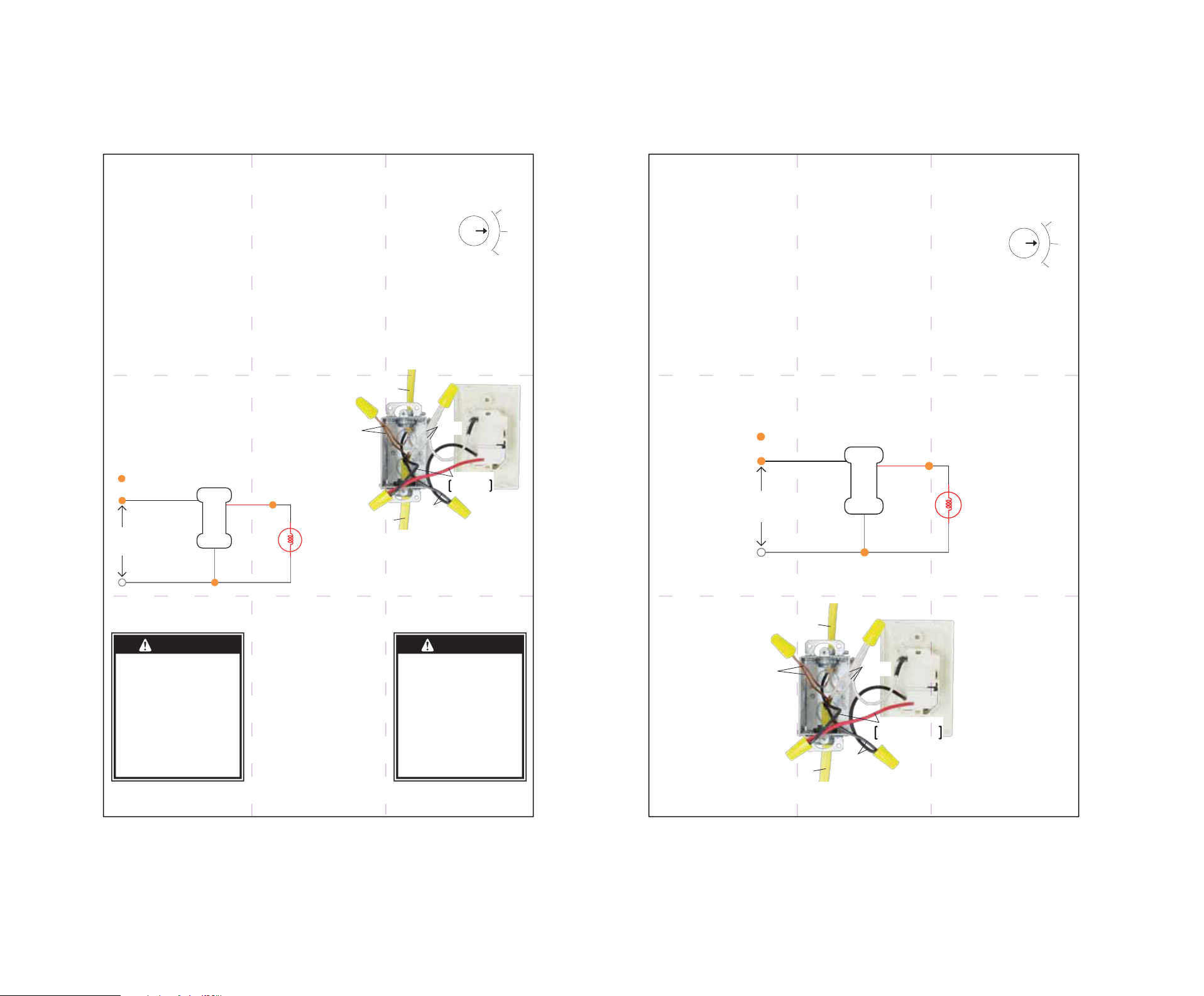
REFER to the wiring diagram.
5. If a ground wire was connected to the old switch, put a twist-on connector
on the end of the ground wire and push the connector and ground wire into
the back of the box.
6. Mount the timer securely with long mounting screws provided. Reattach
cover plate by snapping on to the main timer unit.
7. Restore power at fuse box or circuit breaker.
OPERATION:
The timer has 3 settings ON, OFF, and TIMER. To control the load manually,
place the slide switch in the “ON” or “OFF” position. To use the timer,
1. Place the slide switch in the “TIMER” position
2. Rotate the dial Clockwise until the desired time lines up with the arrow in the
center dial.
LOAD
125VAC, 15A Resistive
125VAC, 15A General Purpose
125VAC, 1250W Tungsten
125VAC, 1/2 HP
10
11
12
FÁCIL INSTALACIÓN:
Antes de la instalación, apague la alimentación en la caja de fusibles o disyuntor.
NOTA: Para uso con aplicaciones de un interruptor unipolar instalado de forma
permanente.
1. Retire la placa de pared y el interruptor unipolar, si existe.
2. Mediante un pequeño destornillador de punta plana, apalanque suavemente la cubierta frontal de
temporizador de pared para soltarla de la unidad principal del temporizador; deje a un lado la cubierta para
utilizarla más adelante.
3. Pele 3/ 8 pulg. de aislamiento del cable de construcción.
4. Conecte los cables mediante los conectores de rosca que se suministran (use con alambre de cobre
únicamente). El cable conductor NEGRO al conductor neutro del circuito. (A menudo el cable neutro se
encuentra contra la parte posterior de la caja del interruptor, unido a una tuerca para cable. Si no está seguro
de cuál cable es cuál o no puede localizar el cable neutro, consulte a un electricista certificado). CONSULTE el
diagrama de cableado.
5. Si se conectó un cable de conexión a tierra al interruptor antiguo, coloque un conector de rosca sobre el extremo del
cable a tierra y empuje el conector y el cable a tierra hacia la parte posterior de la caja.
6. Monte el temporizador de forma segura con los tornillos largos de montaje que se suministran. Coloque la cubierta
nuevamente ajustándola contra la unidad del temporizador principal.
7. Restablezca la energía en la caja de fusibles o disyuntor.
OPERACIÓN:
El cronizador tiene tres posiciones: ON (activado), OFF (de-activado) y TIMER (cronizador). Para controlar la carga
manualmente ponga el conmutador corredizo en la posición “ON” o “OFF”. Para utilizar el cronizador:
1. Poinga el conmutador deslizante en la posición “TIMER”.
2. Gire el cuadrante en sentido de reloj hasta que el tiempo deseado se acople con la flechita en el centro del cuadrante.
125VAC, 15A Resistiva
125VAC, 15A Servicio General
125VAC, 1250W Tungsteno
125VAC, 1/2 HP (caballo)
10
11
12
Typical Wiring Schematic
= Wiring Nut
Black
120 VAC
Power
Source
White
WARNING
Risk of electric shock
•
Shut off power at fuse box or circuit
breaker before installation
•
Do not use in wet locations
•
Use indoors only
Risk of fire
•
Do not exceed electrical ratings
•
Use copper wire only with this device
Timer
White
Red
White
Black
Light
GROUND
[GREEN or BARE]
NEUTRAL
[WHITE]
LOAD
BLACK In-Wall
Red on Timer
LINE
LINE
[BLACK]
www.jascoproducts.com
ADVERTENCIA
Riesgo de choque eléctrico
• Corte la corriente antes de efectuar
una instalación
• No lo use en lugares húmedos
• Use solamente en interiores
Riesgo de incendio
• No exceda los límites eléctricos
permitidos
• Utilícelo con alambre de cobre
únicamente
15068
Manual Version 2
11-24-2009
Esquema de cableado típico
= Tuercas para cable (empalmes plásticos)
Negro
Fuente de
alimentación
120 VCA
Blanco
CARGA
A TIERRA
[VERDE or DESNUDO]
Línea
Temporizador
Línea
[NEGRO]
Rojo
Blanco
NEUTRO
[BLANCO]
CARGA
NEGRO En Pared
Rojo en Temporizador
Negro
Luz
Blanco
 Loading...