

Page 1
INSTRUCTIONS
GEK—
36767
INSTANTANEOUS
MODEL
D.C.
UNDERVOLTAGE
TYPE
PJV
12PJV11BK(-)E
RELAY
GENERAL
ELECTRIC
Page 2
DESCRIPTION
APPLICATION
RATINGS
TABLE
COIL
TABLE
CHARACTERISTICS
TABLE
CONSTRUCTION
OUTLINE
RECEIVING,
ACCEPTANCE
INSTALLATION
LOCATION
MOUNTING
CONNECTIONS
ADJUSTMENTS
PERIODIC
SERVICING
RENEWAL
AND
BURDENS
CONTACT
1
CIRCUIT
2
OPERATING
PICKUP
RELAY
PICKUP
3
DROPOUT
PLUNGER
CASE
VISUAL
MECHANICAL
ELECTRICAL
MECHANICAL
ELECTRICAL
PARTS
RATINGS
RATINGS
AND
CALIBRATION
VOLTAGE
TIME
UNIT
DIAGRAM
HANDLING
TESTS
INSPECTION
PROCEDURE
CHECKS
AND
PRINCIPLES
DROPOUT
AND
INTERNAL
AND
STORAGE
INSPECTION
TESTS
AND
ROUTINE
CHECKS
CHECKS
GEK-36767
CONTENTS
BURDENS
DEFINITIONS
CONNECTIONS
MAINTENANCE
DIAGRAM
PAGE
3
3
3
3
3
3
4
4
4
4
4
4
5
5
5
5
5
5
6
6
6
6
7
7
7
7
7
7
7
7
8
8
8
2
Page 3
for
application
out
setting
plug
outline
that
shown
coil
circuit
regard
applying
voltage
The
is
is
in
The
to
PJV11BK
on
available
and
mounting
required
Figure
PJV11BK
polarity.
this
when
of
relay,
it
on
the
2.
this
is
relay
D.C.
relay.
which
and
relay
set
is
a
systems
The
permits
dimensions
furnished
is
designed
relay
should
The
contacts
Table
3
to
drop
operated
DC
to
PJV11BK
disconnection
for
with
be
should
should
out
detect
the
the
to
connected
be
at
the
single
short
relay
relay
relay
provide
be
used
consulted
desired
GEK-
36767
DESCRIPTION
unit
instantaneous
circuits
comes
in
the
given
given
an
contact
in
of
are
is
APPLICATION
high
speed
to
the
portion
to
initiate
to
insure
value.
that
reduce
SI-E
non-drawout
circuits
Figure
in
Figure
undervoltage
of
the
that
undervoltage
3.
8.
the
D.C.
desired
the
relay
the
from
The
The
detection
system
case.
the
outline
internal
system
action
will
device.
voltage
However,
front
for
connection
on
being
on
low
pick-up
of
the
D.C.
monitored
voltage.
for
It
below
the
the
relay.
external
systems.
normal
is
intended
the
standard
diagram
drop
The
resistor
is
The
without
When
system
CONTACT
The
interrupting
RATINGS
contacts
ratings
are
are
rated
given
at
5
amperes
in
Table
AC
VOLTS
115
230
460
DC
VOLTS
125
250
48
24
RATINGS
for
continuous
1.
TABLE
INTERRUPTING
TNDUCTIVE
0.5
INDUCTIVE
1.0
0.5
0.3
0.15
AND
2
1
BURDENS
duty
1
RATINGS
AMPS
AMPS
and
at
30
amperes
NON-INDUCTIVE
5
2
1
NON-INDUCTIVE
5
2
1
0.3
for
tripping
duty.
The
operating
the
external
resistor
These
resistance,
cuil.
relays
resistor.
every
further
the
but
are
Ratings
These
possi
information
purchaser’s
ic
the
no
such
supplied
and
nsttuCtiOfls
Pie
Cxtient
assurance
and
Table
operating
caltinyency
purposes,
aequu
with
burdens
2
gives
do
be
dosirod
ted
given
is
COIL
CIRCUIT
external
an
given
for
the
be
putt
purport
or
products
vi
riot
tier
ti
continuous
resistance
to
in
connection
should
particu
should
,ies,.
respect
coil
nOt
to
the
the
cover
this
be
r
to
resistor
referred
be,!
lal
RATINGS
relay
voltage
for
these
all
duta:ls
with
p’binru
Ir
herOun
c-r,des
ncra,
tic
AND
which
are
or
thiS’S,
usret
an,!
BURDENS
is
for
the
rating,
relays.
v,’’.jtcs,’
,‘..t,.
In.
rise
w:
ri
.ippf
-jhic
c
ird,
‘cances
to
be
operating
calibrating
:0
pr:
ar.’
h
,rie,
‘,!iJI,
tu’,Oau$C
it0
t
yr
r.
wired
a::im
Cr
:.
Comj’accy
tPEP
v
the:,
in
coil
.
nor
eu:nt,-’rc.cn,,.
ci
-
nd
vary
series
range,
to
Sut
fi:c’ntli
NFL
grett4%.
wired
;rcv:dr
ut
,aodards;
with
in
burden,
for
Sbouad
for
the
series
external
with
3
Page 4
GEK-36767
TABLE
2
OPERATING
These
opened
or
An
coil.
type
effect
of
This
circuit
on
temperature
PICKUP
AND
Pickup
increasing
contacts
pickup
A
RELAY
voltage.
normally
CALIBRATION
These
for
the
by
various
adjusting
calibrations
tube.
PRINCIPLES
plunger
closed
external
external
prevents
relay
operating
insignificant
DROPOUT
voltage
voltage
will
close
open
contact
relays
operating
the
vertical
appear
relays
by
armature
an
resistor
resistor
DEFINITIONS
is
defined
is
applied
when
Reset
voltage
defined
are
calibrated
on
the
RATING
VOLTS
operate
is
self
voltage.
in
the
applied
coil
position
top
700
which
included
has
heating
terms
as
to
is
as
—
external
of
DC
on
a
of
the
the
the
a
at
of’
the
resistance
The
CAL.
RANGE
DROPOUT
280
-
the
principle
is
drawn
as
part
and
variations
high
the
total
voltage
relay.
voltage
voltage
contact
the
factory
resistor
the
armature
nameplate
VOLTS
580
AT
RATED
67
CHARACTERISTICS
BURDEN
of
electromagnetic
vertically
up
of
these
is
which
is
dropout
relays
much
in
ambient
value
resistance.
the
voltage
the
open
makes
decreased
relay
when
that
resistor
circuit
at
Dropout
is
gradually
which
at
which
for
combinations
on
the
and
plunger
correspond
WATTS
VOLTS
into
to
higher
temperature
normally
s
the
will
the
volts.
used
to
COIL
OHMS
solenoid.
a
be
connected
than
changes
open
voltage
from
assume
relay
Table
in
rod.
the
scrihed
RESISTOR
345
attraction.
that
in
contacts
some
is
2
these
The
four
EXTERNAL
OHMS
7000
The
in
series
of
the
from
operating
having
operating
will
at
which
level
its
of
de—energized
completely
shows
the
relays.
factory
marks
on
1
contacts
with
an
appreciable
coil
close
the
normally
voltage
de—energized.
calibrating
Dropout
dropout
the
calibrating
are
the
coil.
resistance
when
above
position.
is
set
voltage
operating
This
with
gadually
closed
ranges
To
should
plunger
coil)
corresponds
dropout
gradually
is
When
That
is,
which
at
PICKUP
Dropout
percentage
wEth
two
voltage
Tnis
set
the
be
set
so
in
its
calibrations
reduced.
these
with
applied
the
normally
VOLTAGE
voltage
of
dropout
normally
is
which
percentage
relay
to
that
its
de-energized
to
the
are
relays
voltage
open
and
voltage
open
or
less
than
will
bottom
lowest
the
are
pickup
one
dropout
position.
voltage
properly
gradually
contacts
that
normally
145
cecrease
at
edge
dropout
voltage
percent
one
t5
adjusted,
open.
is
a
as
of
just
The
voltage
percent
reduced,
are
function
open
of
the
the
lines
scribed
not
and
set
dropout
factory
with
mark
calibration
which
at
they
the
independently
of
one
dropout
voltage
calibrated
the
highest
will
relay
the
dropout
normally
voltage.
corresponding
on
listed
the
relay
dropout
will
reset
adjustable.
voltage
closed
setting
voltages,
the
on
will
in
one
contact,
is
scribed
calibrating
the
nameplate
dropout
smooth
within
setting.
increased
the
two
The
pickup
adjustable
marking
when
motion
percent
relays
For
as
tube
and
the
D.C.
will
shown
to
will
with
(closest
so
on.
applied
the
of
the
pickup
operated
occur
in
table
armature
the
relay
to
The
voltage
reset
voltage
at
the
factory
position.
at
relays
some
3.
a
4
Page 5
GEK-36767
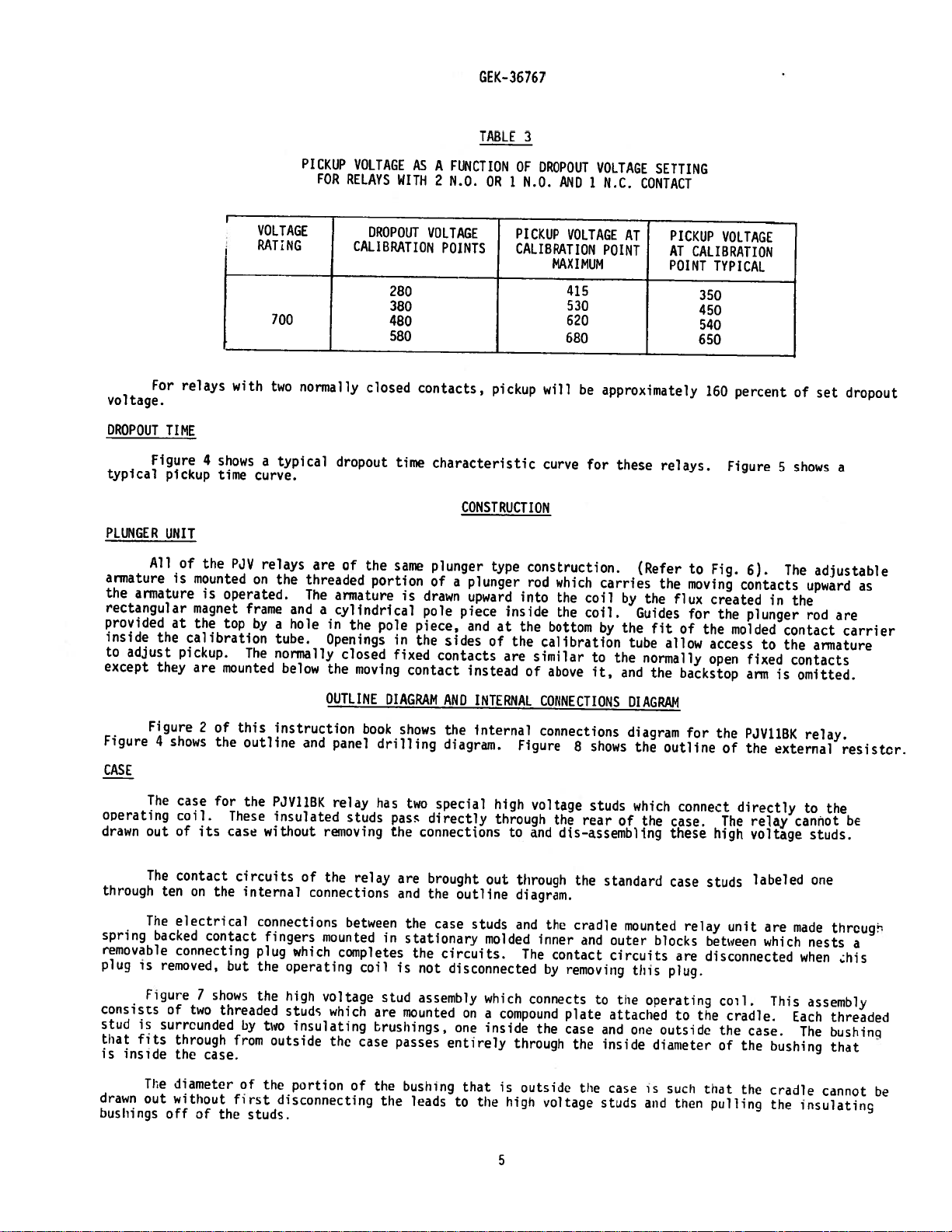
TABLE
3
For
voltage.
DROPOUT
Figure
typical
PLUNGER
All
armature
armature
the
rectangular
provided
inside
to
adjust
except
Figure
Figure
4
CASE
TIME
pickup
UNIT
is
at
the
they
shows
relays
4
the
of
mounted
is
magnet
the
calibration
pickup.
are
of
2
the
with
shows
time
PJV
on
operated.
frame
top
by
The
mounted
this
outline
PICKUP
VOLTAGE
RATING
700
two
normally
a
typical
curve.
relays
the
threaded
The
and
a
hole
tube.
normally
below
instruction
and
VOLTAGE
FOR
RELAYS
CALIBRATION
dropout
are
of
armature
a
cylindrical
in
the
Openings
closed
the
OUTLINE
panel
DROPOUT
280
380
480
580
closed
the
same
portion
pole
in
fixed
moving
DIAGRAM
book
drilling
AS
WITH
contacts,
time
is
piece,
the
contact
shows
VOLTAGE
drawn
pole
A
FUNCTION
N.O.
2
OR
POINTS
pickup
characteristic
CONSTRUCTION
plunger
type
ofaplunger
upward
piece
and
sides
at
of
contacts
instead
AND
INTERNAL
the
internal
diagram.
OF
DROPOUT
M.D.
1
PICKUP
AND
VOLTAGE
CALIBRATION
MAXIMUM
415
530
620
680
will
curve
construction.
rod
which
into
the
the
of
the
the
bottom
calibration
similar
above
inside
are
CONNECTIONS
connections
Figure
8
VOLTAGE
1
N.C.
AT
POINT
approximately
be
for
these
carries
coil
by
coil.
by
the
the
to
it,
and
shows
SETTING
CONTACT
PICKUP
AT
POINT
relays.
(Refer
the
the
flux
Guides
fit
tube
allow
normally
the
OIAGRAM
diagram
the
outline
VOLTAGE
CALIBRATION
TYPICAL
350
450
540
650
160
percent
Figure
to
Fig.
moving
6).
contacts
created
for
the
the
plunger
molded
of
access
open
the
of
fixed
arm
PJVI1BK
the
backstop
for
5
in
to
is
external
of
shows
The
upward
the
rod
contact
the
contacts
omitted.
relay.
set
dropout
a
adjustable
are
carrier
armature
resistor.
as
operating
drawn
through
spring
removable
plug
is
consists
stud
is
that
fits
inside
is
The
drawn
out
bushings
The
case
coil.
of
out
The
contact
ten
Tne
electrical
backed
connecting
removed,
Figure
of
surrcunded
through
the
diameter
without
off
its
on
7
two
case.
of
for
These
case
the
contact
but
shows
threaded
first
the
the
without
circuits
internal
connections
fingers
plug
the
the
by
two
froii
of
the
studs.
PJV11BK
insulated
removing
of
the
connections
mounted
which
operating
high
voltage
studs
insulating
outside
portion
disconnecting
relay
studs
relay
between
completes
coil
which
the
case
of
has
two
pass
connections
the
are
and
the
in
stationary
the
is
not
stud
assembly
are
mounted
brushings,
passes
the
hushing
the
leads
special
directly
brought
the
outline
case
circuits.
disconnected
on
one
entirely
that
to
out
studs
molded
which
a
inside
the
high
voltage
through
to
and
through
diagram.
and
inner
The
connects
compound
the
througn
is
outside
high
S
studs
the
rear
dis—assembling
the
standard
the
cradle
and
contact
by
removing
to
plate
case
and
the
inside
the
voltage
studs
which
of
the
mounted
outer
circuits
this
the
attached
one
case
connect
case.
these
case
blocks
are
plug.
ooerating
to
outside
diameter
su’i
is
tnen
and
The
high
studs
relay
betwrcn
disconnected
col.
tne
the
of
that
pulling
directly
relay
voltage
labeled
unit
cradle.
case.
trio
trio
are
which
This
bushing
cradle
the
to
the
cannot
studs.
one
made
nests
when
assemb1
Each
bushinq
The
cannot
insulating
bc
thrcug
a
his
threaded
that
be
Page 6

cradle
of
the
upside
blocks
by
thumbscrews,
external
pulled
been
released.
bushings
unit
with
is
provided
sealing
The
relay
held
is
case.
down.
of
the
To
draw
connections
off
have
the
The
case
wire.
the
for
mechanism
firmly
The
cases
The
connecting
cradle
holds
out
rear
To
been
external
is
suitable
either
in
and
the
the
relay
to
of
the
replace
replaced
connections
mounting.
is
the
and
cradles
case,
connecting
the
high
studs.
the
on
for
mounted
case
plug,
also
unit
voltage
relay
the
either
The
with
are
besides
locks
the
The
high
intact.
in
a
plug
cover
relay
unit,
surface
cover
steel
a
latch
so
constructed
making
the
in
studs
the
voltage
GEK—JbJbi
framework
at
latch
place.
is
first
are
unit
reverse
studs.
or
attaches
the
top
that
the
electrical
in
place.
removed,
then
can
then
order
semi-flush
to
called
and
the
the
relay
The
and
disconnected
be
easily
is
These
followed
bushings
panel
the
case.
the
cradle
bottom
cannot
connections
cover,
the
connecting
and
drawn
do
mounting
Each
cover
and
and
which
the
out
making
not
and
is
by
a
guide
be
inserted
between
is
plug
insulating
after
certain
allow
an
assortment
screw
complete
a
the
fastened
drawn
the
the
has
pinat
in
the
respective
to
out.
bushings
latches
that
the
removal
of
provision
cnit.
the
case
the
are
have
insulating
of
hardware
back
case
The
the
for
This
then
relay
a
These
to
protect
substained
claim
at
once
Apparatus
Reasonable
injured
cartons
on
the
If
outside
or
the
in
operation
Immediately
that
no
damage
VISUAL
INSPECTION
Check
the
relay
received
Examine
signs
tact
MECHANICAL
of
leads
physical
extend
INSPECTION
relays,
them
in
Sales
the
a
of
that
against
transit.
with
Office.
care
adjustments
relays
place
of
the
has
the
the
when
the
should
are
that
the
relay.
upon
been
nameplate
agree
relay
damage,
striaght
not
included
damage.
If
injury
transportation
be
disturbed.
not
to
is
free
case
may
receipt
sustained
with
the
by
visual
and
that
back
tmmediately
or
exercised
be
installed
from
find
of
relay
a
in
stamping
requisition.
inspection
all
from
RECEIV1NG
as
a
part
damage
company
in
unpacking
immediately,
moisture,
its
way
inside
ACCEPTANCE
inspection
an
shipment
to
insure
that
screws
the
contacts
HANDLING
of
a
upon
receipt
resulting
and
promptly
dust
when
and
that
that
there
are
tight.
and
AND
control
from
the
and
TESTS
and
the
the
are
have
STORAGE
panel,
of
rough
notify
relay
they
met3llic
the
cover
acceptance
relay
moael
no
Also
not
a
relay,
handling
in
should
chins.
calibrations
number,
broken
check
been
will
examine
the
nearest
order
be
stored
is
removed
test
or
to
see
deformed.
be
shipped
is
that
Foreign
should
rating
cracked
that
it
evident,
General
none
in
matter
and
have
and
molded
the
in
for
any
of
their
cause
be
made
not
calibration
flexible
cartons
damage
file
Electric
the
parts
original
collected
trouble
to
been
parts
designed
damage
a
are
in
insure
disturbed.
range
or
other
moving
the
of
con
It
1.
2.
is
recommended
Operate
from
friction
just
making
me
wipe
normally
either
The
gap
armature
the
on
open
contact
between
reset.
that
plunger
or
there
a
normally
contact
arrangement.
the
the
binds.
is
following
on
each
less
open
gap
backstop
If
than
with
unit
two
nomally
1/64
or
closed
the
Backstops
and
contact
mechanical
by
hand
inch
contact
armature
should
adjustments
and
open
gap
fully
brush
6
allow
contacts
on
should
be
at
the
reset
present
the
it
other
to
are
be
tip
be
chccked:
reset
to
i:resent,
contact.
approximately
should
above
should
be
all
insure
observe
3/64
approximately
normally
be
approximately
that
that
mci.
open
the
unit
with
The
3/32
contacts
1/16
one
inch
is
with
free
contact
for
only.
the
Page 7

GEK-36
767
ELECTRICAL
DROPOUT
1.
aligned
point
given
this
setting.
test
To
external
normally
indicates
resistor
open
drop-out
visually.
To
simply
connected
directly
Check
The
location
facilitate
The
Figure
relay
3.
TESTS
AND
PICKUP
with
on
the
contact
check
smooth
for
inspection
should
outline
The
the
relay
to
top
the
a
will
when
for
the
to
should
and
-
The
mark
nameplate.
proper
for
variable
indicate
voltage
the
operation
relay
operation
be
testing.
mounted
be
diagram
units
on
clean
for
are
the
It
operation,
D.C.
on
but
without
of
plunger
and
on
the
normally
calibration
should
supply.
pick-up.
lowered
s
not
the
dry,
a
vertical
external
supplied
tube.
be
sufficient
preferable
it
is
A
contact
Similarly,
the
from
for
calibration,
resistor.
operating
when
INSTALLATION
LOCATION
free
from
dust
MOUNT
IN
surface.
resistor
CONNECTIONS
from
This
the
corresponds
to
check
to
indicating
indication
an
picked-up
a
D.C.
the
relay.
PROCEDURE
excessive
and
C
The
outline
is
s,own
factory
dropout
connect
light
condition.
supply
end
in
Figure
with
to
the
and
relay
the
or
ohmmeter
on
a
Reset
of
not
vibration,
panel
8.
the
bottom
minimum
pickup
in
dropout
of
series
conncted
normally-closed
must
be
over
35
and
well
diagram
is
of
each
checked
volts
shown
the
calibration
unit
with
to
contact
can
lighted
armature
at
the
a
be
to
in
Internal
One
12
not
B&S
The
binding.
is
It
case
it
will
The
knurled
If
dropout
turn
view
in
of
gage
plunger
required
With
decrease
the
the
No.
and
in
its
which
of
the
setting.
Gradually
high,
increasing
oacteristics
C
thataperiodic
it
is
recommended
MECHANICAL
CHECKS
connection
the
mounting
‘opper
desirable
mounted
and
used.
be
armature
a
variable
is
armature
applied
section.
of
the
test
unit
dropout
the
too
vital
program
that
wire
should
that
in
to
applied
low,
to
voltage
the
diagram
studs
or
be
the
its
voltage
the
approximate
source
voltage
turn
ride
with
role
be
following
is
shown
or
screws
equivalent.
its
manually
final
setting
permanent
may
of
D.C.
the
lower.
the
PERIODIC
of
protective
followed.
points
should
operated
location
be
set
position
voltage
and
note
armature
Once
unit
CHECKS
Unless
in
of
as
dropout
dropped
relays
be
Figure
be
(JSTMENTS
ADJ
the
iid
follows.
apply
the
ride
to
AND
otherwise
cheked
2.
permanently
make
to
required
with
on
the
sufficient
voltag2
lower
voltage
out.
ROUTINE
in
the
at
an
grounded
that
sure
dropout
the
With
tube
th.
voltage
relay
wired
the
relay
corresponding
voltage
at
which
the
in
th.
set,
:‘librating
check
votage
is
Pickup
MAINTENANCE
a.cn
ope
dictatoi
by
interval
of
unusual
of
by
assembly
rlay
a
from
a
conductor
is
be
performed
to
the
external
de-energized
the
to
to
the
relay
L,35
tube,
pickup
should
power
voltage
be
sy;te,
environeental
to
one
working
turn
desired
out.
if
described
as
two
not
with
resistor
to
pick
dropout
by
t
years.
less
smoothly
the
the
bottom
dropout
it
gradually
is
important
conditions,
than
is
in
relay
with
up.
too
the
excessive
Manually
friction
operate
or
the
voltage
tendency
unit
to
armature
bind.
and
allow
it
to
reset
to
make
sure
that
no
a
7
Page 8

Check
gap
is
open
approximately
contact
Examine
cleaned
with
surface.
factory.
ELECTRICAL
Check
It
are
is
noted,
that
differences
1.
Friction
armature
leads
between
2.
Moving
centrally
follows:
to
see
ar
the
a
burnishing
Burnishing
Do
not
CHECKS
the
dropout
not
recormiended
as
in
test
If
does
to
the
the
armature
Contact
located.
that
the
3/32
approximately
contact
tools
use
knives,
and
long
as
equipment
there
is
not
have
moving
contacts
and
Leads
-
If
contacts
inch
surfaces
tool,
designed
files
pickup
that
the
or
any
a
tendency
calibrating
The
these
with
the
1/16
for
which
especially
or
voltage
the
relay
by
human
tendency
are
flexible
moving
have
inch
signs
consists
abrasive
relay
is
to
not
still
to
moving
contact
approximately
armature
above
the
of
of
for
paper
of
the
be
readjusted
within
error.
SERVICING
bind
rotate
formed
tube.
contact
GEK—36767
reset.
stationary
tarnishing
flexible
a
cleaning
or
relay
limits.
or
excessive
and
bind
properly.
leads
leads
have
3/64
Check
cloth
as
when
as
inch
to
contact
or
corrosion.
strip
relay
of
described
minor
Such
friction
the
relay
Also
check
should
been
deformed,
wipe
see
of
contacts
any
setting
deviation
be
and
that
tips.
metal,
kind
in
the
is
present,
operates.
that
formed
that
the
Silver
with
can
to
clean
installation
variations
can
no
foreign
to
they
the
back
contacts
an
be
obtained
be
check
If
keep
should
normally
Stops
etched,
relay
from
introduced
to
it
does,
matter
the
be
open
on
the
should
roughened
from
contacts.
section.
the
see
the
is
moving
reshaped
contacr.
normally
be
the
previous
by
that
flexible
present
assembly
as
the
The
bend
closed
The
the
moving
3.
See
wipes
4.
Fixed
The
is
This
If
only
grams.
For
It
prompt
When
specify
number.
furnished.
lead
should
should
contact.
whole
lead
leads
are
parts.
the
acceptance
are
adjusted
Contact
stationary
the
face
face
may
contacts
one
normally
In
all
cther
is
recomended
replacement
ordering
quantity
If
possible,
be
Initial
applied
be
are
this
contact
required,
have
vertical
The
should
formed
tests
by
contact
to
measured
replaced
closed
arrangement
that
of
any
renewal
give
right
a
with
lead
should
lie
in
correctly
and
forming
Tension
normally
the
with
or
contact
codes,
sufficient
that
parts,
name
the
angle
the
a
installation
or
contact
readjusted
the
all
are
worn,
address
of
part
General
bend
lead
then
vertical
providing
bending
rests
tip
a
gram
is
used,
normally
contacts
quantities
wanted,
Electric
when
going
down
flow
in
plane
the
sections
the
onamember
which
gauge.
for
wipe
the
open
should
RENEWAL
broken
the
or
nearest
and
Company
it
leaves
foranormally
a
smooth
and
not
relay
is
for
stationary
called
necessary
is
or
gap,
initial
contact
have
PARTS
of
renewal
damaged.
Sales
give
requisition
the
arc
blow
not
contact
contacts.
the
initial
tension
should
about
parts
Office
complete
tail
to
out
binding
contact
to
part
on
have
five
nameplate
of
the
open
the
contact
terminal
horizontally.
due
gap
and
stop
the
tension
this
about
grams
be
carried
of
the
number
moving
to
foreign
wipe
contact
should
contact
five
initial
General
data,
on
which
contact
and
screw
Binding
adjustments.
arm.
from
be
should
grams
tension.
in
stock
Electric
including
the
up
on
matter
Initial
checked.
initial
for
the
its
to
relay
button,
a
molded
will
or
tension
stop
be
about
enable
Company,
serial
normal]”
stop
bent
Gaps
arm.
When
tension.
was
this
base.
when
and
14
the
8
Page 9

GFK—35757
FIG.
1
(Photo
Not
Available)
Type
PJV1IBK(-)E
9
Relay
Out
Of
Case-Front
View
Page 10

20
LLL
TTT
GEK—36767
COCE
NI’MPFP
02
2!
22
-----EZTh---
EXTEP’AL
RESI
‘\1
MA(E
7
CC*’NFCTIOt1S
/‘
2
DOTtED
!HORTING
ARE
PEUIRED
IF
FARS
n
e
STOP
IC
*
S!OPT
FI3C-EPS
FIG.
2
(0245A3667—1)
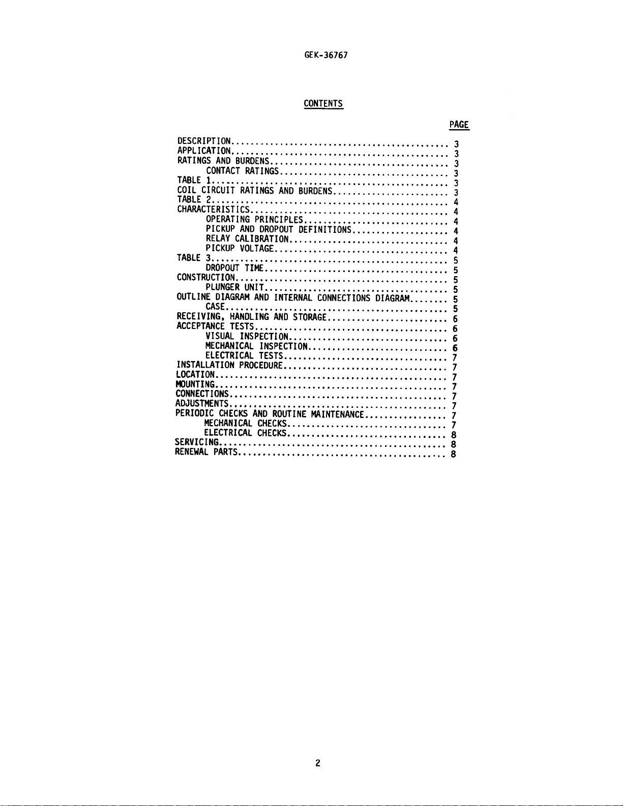
NOTE:
Internal
141G[1
VftTAGE
THROUGH
ftSHINGS
REFORE
Connections
10
SThDS
REAP
CF
VST
CRADLE
Diagram
CASE.
RFHOVED
FE
Cfl
FE
For
Model
(2!
&
22)
LEADS
FRO!A
W:THDPM.
PJV11BK(—
PROJECT
A’D
ThESE
SIUDS
Page 11

LLJ
CD
a
Wa
-a
I
a
a
0
‘-a
has
I-.
a
.,
.,
—
.,
—
I.
I
%ID
4
a
a
—
‘-a
-C
-
-
LU
C
a
I
_____
4
4—fr
C’
‘CL
F
C-
-
a
0
I
C’
LU,
a,
-
a
or
a
a
0
LU.
La)
-j
I
Las
—
I
—
In
cL’1
CD
(C)
cC’
CD
-
C’”’
t
—
,-
-r
0
t
_
C’
F
C
C)
a-’
a.,
F
C’
C
C
‘
-n
‘C
,
,_,
-,
La
-C
CD
C)
0
CD
C,)
C’
L
a
0
C
0
a
CL.
c)
‘a
LU
Page 12

GEK-36
767
PLV
RELAY
DROPOUT
30
26
0
z
22
0
‘3
-J
----—-
E
r
iN
L.a
10
PICRUP
INITIAL
VOLTAGE
A—CTOPER
100
VOLTAGE
IS
DECREASED
CENT
.—----
VOLTS
—
115
OF
......
C
Los
A—C
VOLTS
SUODEMIT
PICKuP
I
MG
TINE
CURVE
A—C
FROM
VOLTAGE
-—--
fF_bCONTAc_._
4
_L
115
SNOIN
VOLTS
8ELC.
—
I
-,
-
—
CYCLE
(60
CYCLE
;:::7’
NASE
ONE
6
2
.0
10
‘
20 30
FINAL
OPENING
VOLTAGE
tIw(
.1
NO
VALUE
OF
—
PERCENT
a’
CONTACT
o
OF
60
PICKUP
70
VOLTAGE
eo
90
100
4
(y.379..1)
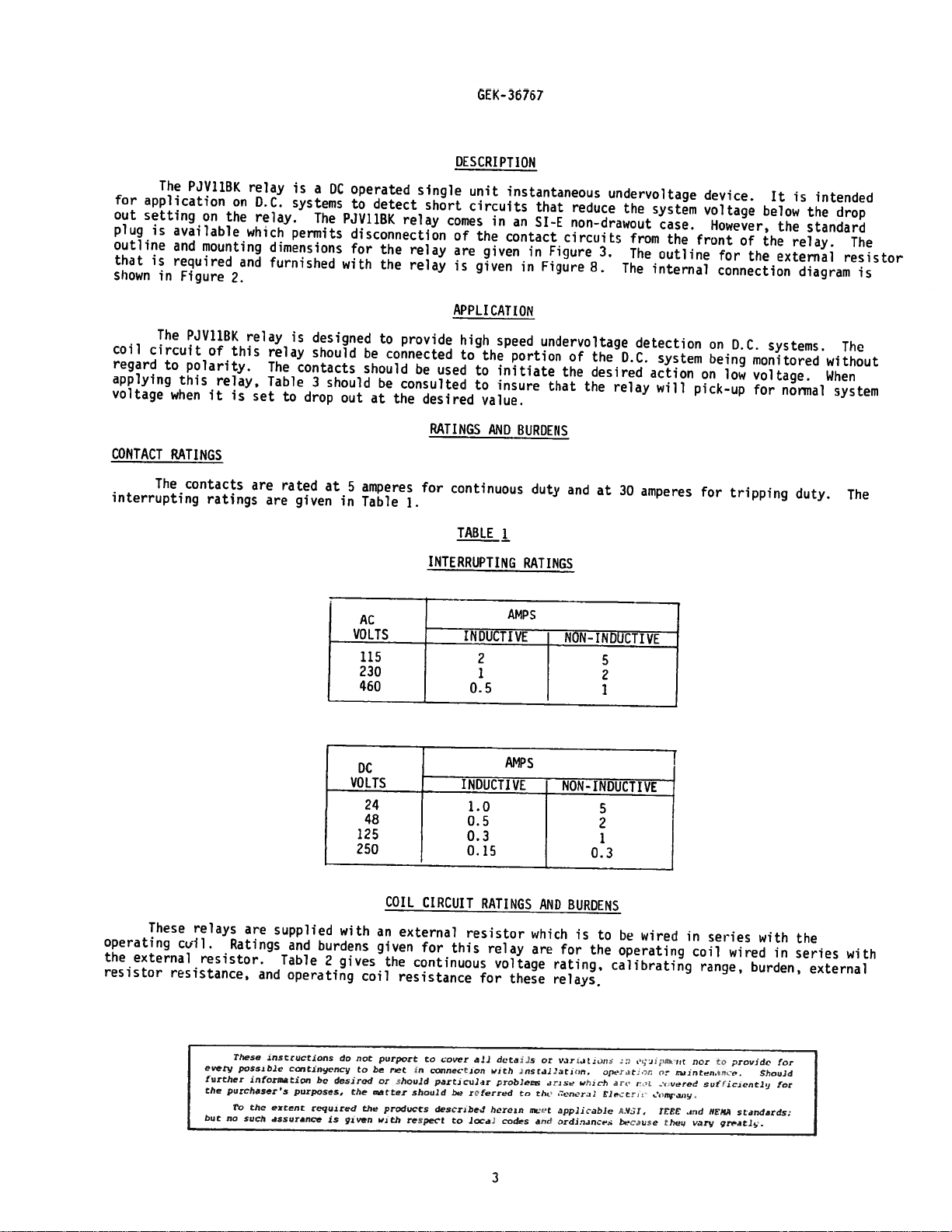
Typiciil
Dropout
Tiuie
Ch1rdc1r
i.,t
r
Ic
PV11I(—)[
1?
Page 13

GE
(-36767
70
I
60
N
I
I
30
S
E
C
20
0
N
0
S
0
(—(3
,-1)
1
VOLTAGE
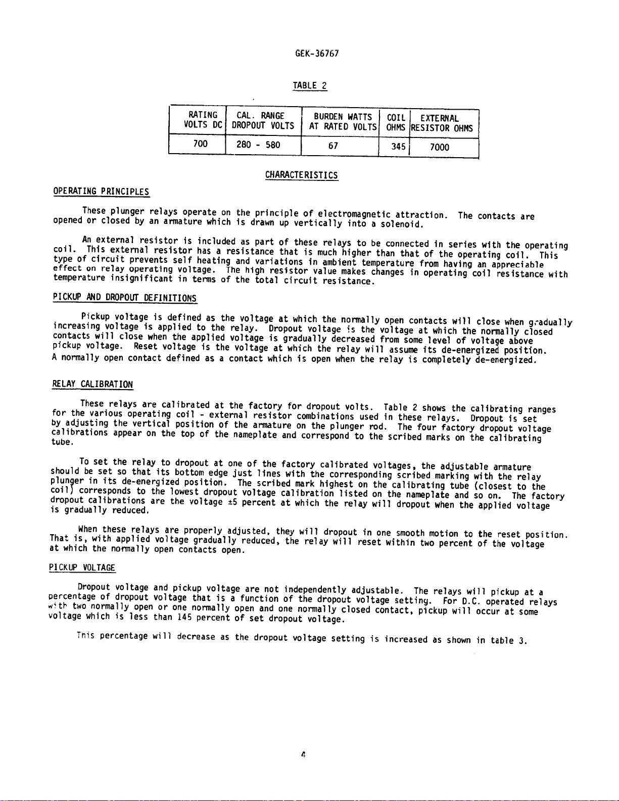
Tyoic,i
cIuL
2
IN
U1TIPLES
Tu;Ie—Voltdge
OF
PICN—UP
Chdracteristic
3
For
PJVIIBK(-)E
13
Page 14

GEK—36767
MAGNET
CALIBRATING
TUBE
FAC
I
t
I
ft...
ABLE
MOVING
CONTACT
FIG.
(8009444)
6
•1
Typical
Plunger
r
Voltage
14
Unit
Used
STATIONARY
CONTACT
CONTACT
CARRIER
ASSEMBLY
In
These
Relays
Page 15

G[K-36757
C
(
RELAY
CASE
OF
B
,jJ
FIG.
7
(0257A3242_o)
Diagram
Of
High
Voltage
Stud
Assembly
FIG.
(403A119-1)
8
Outline
For
External
Resistor
BARE
HOLE
STRIP
Page 16

GE
Power
Management
Anderson
215
Markham,
Canada
Tel:
Fax:
www.gecomIindsysIpm
L6E
(905)
(905)
Avenue
Ontario
1B3
294-6222
201-2098
 Loading...