

Page 1

for
This
relay
INSTRUCTIONS
supplement
model
12IAC8OL(-)A.
TIME
in
conjunction
OVERCURRENT
TYPE
MODEL
TAC
12IAC8OL(-)A
INTRODUCTION
with
RELAY
GEH—1788
forms
Insert
the
Booklet-
instructions
GEH-1788
unit
relay
in
GEH-1788
Relay
with
is
1)
2)
The
model
a
seal—in
similar
The
internal
supplement.
The
induction
provide
3
and
4)
ment
in
is
completed,
the
unit
is
open,
tap
value.
time
current
for
model
12IAC8OL(-)A
unit
model
mounted
121AC53A(-)A
to
connections
unit
torque
must
flux
control.
be
to
completed
rotate
torque
will
operate
the
unit
will
curves,
121AC53A(-)A.
DESCRIPTION
consists
in
are
uses
wound
This
the
can
be
on
overcurrent.
not
burdens
of
a
small
described
as
shading
control
in
order
disk.
developed
operate
and
a
single
single
shown
that
When
at
ratings
in
in
figure
coils
circuit
there
the
on
the
When
current
of
IAC
type
ended
GEK-1788
1
on
the
(connected
be
shading
induction
the
shading
levels
this
relay
time
(Si)
except:
of
U-magnet
a
phase
coil
case.
this
up
circuit
disk
coil
to
are
overcurrent
This
to
to
studs
displace
and
circuit
20
times
as
given
Those
nor
to
operation
probls
matter
Instructions
provide
or
arise
should
do
every
are
not
possible
Should
not
to
SYSTEMS
for
.aintenanc..
which
referred
be
POWER
GENERAL•
purport
covered
the
General
to
cover
contingency
further
•ufficiently
MANAGEMENT
all
to
information
Liectric
detafle
be
for
Company.
or
met
be
the
variation.
in
connection
desired
purchaser’s
DEPARTMENT
or
should
ELECTRIC
in
with
puro.ea,
equip..nt
inatal3atioq,
particular
the
Page 2

GEK-
27870
SEAL—IN
CONTROL
WINDINGS
8-70
FIG.
1
GENERAL
=
*
(0226A7211-0)
ELECTRIC
SHORT
INTERNAL
CO..
POWER
1
2
FINGERS
COKNECTIONS
SYSTEMS
3
DIAGRAM
MANAGEMENT
FOR
BUSINESS
4
THE
IACBOL(-)A
DEPT.,
C)
6
RELAY
MALVERN,
(FRONT
PA.
19355
VIEW)
Page 3

INSTRUCTIONS
TIME
OVERCURRENT
RELAYS
GEH-1
788L
IAC53A
IAC53B
IAC53C
TYPES
IA
C5
3
IAC54A
IAC54B
R
GENERAL
ELECTRIC
Page 4
GEH-1788
Tvne
Time
IAC
TOP
TAP
SEAL-IN
UNIT
HOLDING
(0I
SEAL-
TARGET
SEAL-IN
UNIT
STATIONARY
CONTACT,
S[AL
UNIT
STATIONARY
CO
RIGHT
SEAL
MOVING
CON
AC
PIVOT
PLUG
L
IN
FT
N
TA
(.T
N
IN
TACT
3EMBLY
Overcurrent
--
Relay
(ii
‘4
BLOCK
TAP
DIAL
--TIMF
SHAFT
DISK
MAIN
MOVING
CONTACT
M
A
N
IDNARY
STA’
AND
ROUGH
CONTACT
ASS
Si,p,
—
-‘p
MAGNET
0151<
Y
MB
C
L
c’1
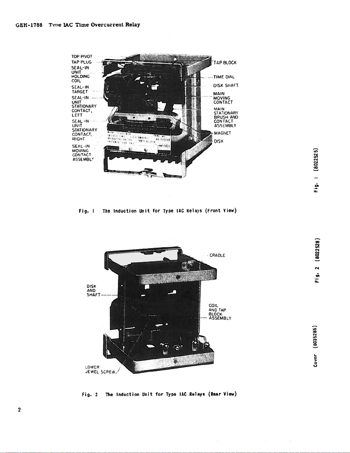
Fiq.
I
DISK
AND
SHAFT
JEWEL
The
SCREW
Induction
—
Unit
for
Type
IAC
Relays
(Front
View)
c..J
c..1
Di
LL
cS-i
LC)
C’,
0
>
0
C-,
View)
Fin.
for
Induction
The
2
Unit
Type
IAC
Relays
(Rear
2
Page 5

TIME
OVERCURRENT
RELAYS
IAC53A(-)A
IAC53B(-)A
IAC53C(-)A
iAC53R(-)A
IAC54A(-)A
1AC54B(-)A
The
overcurrent
acteristic.
overcurrent
The
various
differ
in
the
instantaneous
included.
These
induction
T
Types
on
relays
number
relays
unit
ype
1AC53
relays
They
single-phase
unit
with
with
are
employed
described
of
circuits
and/or
consist
instantaneous
an
Contact
Circuits
One
One
One
One
Two
Two
and
1AC54
very-inverse
a
and
an
of
to
poly-phase
in
this
they
a-c
an
induction
TYPE
INTRODUCTION
Instan.
Unit
No
Yes
No
Yes
No
Yes
relays
time
protect
instruction
close,
tripping
unit
which
are
against
circuits.
and
unit
unit
time
char
book
if
or
per-
A-C
an
is
an
IAC
Trip
Unit
No
No
Yes
Yes
No
No
mits
instantaneous
rents,
use
where
preferred.
composed
is,
the
a-c
tripping
ed
separately
indicates
the
internal
diagrams.
Induc.
One
One
On
One
One
One
or
an
d-c
of
induction
the
Unit
tripping
induction
power
Since
practically
various
unit,
unit),
they
in
the
units
comprising
connections
Outline
D.
&P.
Fig.
20
Fig.
20
Fin.
20
Fig.
20
Fig.
20
‘Fig.
20
for
unitwithana-c
is
unavailable
combinations
the
instantaneous
are,
for
following
and
outline
Conn.
Fig.
Fig.
Fig.
Fig.
Fig.
Fig.
exteremely
tripping
or
all
Type
of
convenience,
text.
each
The
type
andpanel
mt.
a-c
IAC
the
and
12
13
14
15
16
17
high
tripping
relays
above
unit
describ
above
also
cur
unit
(that
and
table
lists
drilling
for
is
are
the
TAC
mounted
tion-disk
current
disk
the
alarm
ary
by
a
current
magnet
delay.
the
left
and
such
unit
picks
up
and
button
a
n’Jer
rurt;2-O-
the
pur.:lianer
but
no
The
relays.
shaft
contact
spiral
acting
There
of
its
contacts
that
picks
up,
remains
Shove
posszble
information
To
Civ
such
INTRODUCTION
induction
Figs.
in
the
construction
operating
carries
or
trip
or
spring
and
its
is
a
the
shaft.
when
up
and
it
raises
beneath
instructions
contingency
‘s
Cxtent
ssura.nce
unit
cradle.
coil
the
circuit
contacts.
to
motion
on
the
seal-in
in
parallel
the
main
seals
a
exposed
the
he
purposes,
requlred
is
and
1
These
type.
on
moving
give
disk
unit
This
target
lower
do
des;rcd
is
qiven
the
basic
2
show
units
Thediskisactuatedby
a
laminated
contact
when
The
the
is
it
disk
proper
retarded
to
give
touches
shaft
mounted
unit
has
with
the
contacts-close
in.
When
into
left
the
released
corner
purport
be
or
matter
products
with
view
met
should
until
not
to
the
INDUCTION
unit
in
all
the
induction
are
of
U-magnet.
which
the
is
contact-closing
by
a
the
correct
on
the
its
coil
main
the
the
seal-in
which
by
of
to
in
connect
particular
should
described
respect
Type
the
induc
completes
station
restrained
permanent
time
front
in
series
contacts
seal-in
unit
latches
pressing
the
cover.
cover
al.!
ion
be
referred
to
local
unit
The
a
to
details
with
problems
herein
codes
UNIT
The
IAC
relays,
characteristics
tripping
cause
closing
to
time
the
rent
four
bination
amperes;
0.5,
0.12,
installation,
to
meet
the
it
to
OPERATING
The
induction
contacts
the
pick-up
delay
setting
characteristics
The
induction
operating
of
0.6,
0.16,
or
variations
arise
the
General
applicable
and
ordinances
APPLICATION
induction
supplying
of
breakers
close
its
which
value
in
closing
of
the
time
coils,
taps
1.5,2.0,
0.8,
0.2,
which
as
2.5,
1.0,
0.24,
in
operation
are
Electric
ANSI,
because
unit
is
the
main
unit
inverse
soundingan
currents
the
the
relay
for
very
and
overload
contacts.
CHARACTERISTICS
unit
are
may
close
as
the
dial
have
set
contacts
(Fig.
shown
one
the
as
current
on
the
tap
is
1).
in
Fig.
RATINGS
unit
is
each
follows,
3.0,
1.2,
0.3
and
equipment
or
not
Company.
IEEE
designed
having
4.0,
1.5
0.4
rrintenance.
covered
and
they
to
a
4,5,6,7,8,10,12,
5.0
and
and
2.0
amperes.
nor
to
sufficiently
NEMA
vary
greatly.
in
all
time
alarm
or
two
increases
block.
determined
The
time-cur
3.
use
any
different
6.0
amperes;
amperes;
provide
Should
standards;
Type
delay
which
circuit-
The
one
com
and
for
for
or
by
of
16
0.1,
3
Page 6

GEH-1788
:
“I
7W
II,
be
I,.
Type
:.;.;;
liii—
I
TIN
P
U
API
HIlt
0.5-4.0
1.5—12.0
2-16
H
::
--
[AC
S
C,
—
Overcurrent
Time
4
4
$
I
UNIT
lIST
I
I
0
5-4
0.
2—16
0-ITO
20-ISO
ia
Relay
1I!11
I
ADJ
INST.
AUJU
17111
I
TI
I
US
UNIT
NUOLISLY
TI
tO
S
I
ENPS
IJI
I
NI
eu
‘I’
P
‘44
I..
‘7
II
N
I.
Ii
441,44744411!
5,2.0,2.5,3.
$7
1F11Ii1II_
I
I
EXTQE[
TIIIE
0,5.0,
r’(E
061
S.O6
(ECO
TAPS
.0,7.0,6.0,
I_L
r[p’)
III
I
7
I
C.5,O.6,O.7,0.8,I.O,I.2,I.S,2.O,2..,3.0,4.0
I.
2.O,2.5,3.0,4.05.0,6.O,7,O,80.,IO.0,I2,I6
•
1IIII1
I
0,
12
I
I
J
CON
:
-
—
4
III
—
——-
I
-
fiiiij
I
I
I
I
.4
.4
.1
.4
3
.2
.1
44
44
17
U
-
13
74fl
.1
5
——
.E
-
4;
—
-
JA
—
.-
——-
I..
44
MULTIPLES
W7IWW
N
$
RELAY
OF
TAP
£
SETTING
.5
I
S
Figure
3
(0888e0270
[3])
Time-Current
Very-Inverse-Time
Curves
for
Characteristics
Type
IAC
Relays
with
4
Page 7

1•C’4
C.,’
cc
c..J
C.,’
cc
U-
Type
IAC
Time
Overcurrent
CALIBRATION
PLATE
ADJUSTABLE
I-.----
POLE
PIECE
TA
N
TA
N
MS
[
UNIT
OPERATING
COIL
TARGET
STATIONARY
CONTACTS
MOVING
CONTACT
ASSEMBLY
0,
LL
EDUS
CONTACTS
SHORTING
COIL
MAIN
COIL
A
-C
TRIPPING
UNIT
Relay
GEH-1788
Fig.
The
30
amperes
The
current-carrying
selection
as
indicated
Function
Tripping
Carry
Operating
Resistance
Impedance
If
aaxiliary
such
that
the
contacts
protective
L
Type
current-closing
for
of
the
in
Duty
Continuously
Range
at
60
the
tripping
relay
tripping
the
or
relay.
AC
voltages
tap
the
cy
should
the
Relay
(Front
ratings
on
following
2-Amp
current
be
current
target
with
View)
rating
not
the
target
table:
Amperes,
30
3
2-30
0.13
0.53
exceeds
used,
does
and
an
Instantaneous
of
the
exceeding
affected
are
and
a-c
Tap
seal-in
or
0.2
contacts
250
Amp
d-c
volts.
by
Tap
Unit
is
the
coil
5
0.3
0.2-2
7
52
the
connections
not
seal-in
30
pass
amperes
coils
being
through
of
an
the
INSTANTANEOUS
Fig.
Burdens
following
five
amperes
Volt-ampere
of
the
of
current,
Coil
Amps
4-16
1.5-6
0.5-2
0.1-0.4
5
table.
three
Freq.
60
50
25
60
50
25
60
50
25
60
5tJ
UNIT
Type
for
coils
up
IAC
(Rear
BURDENS
the
These
based
burdens
can
20
to
Tap
4
4
4 5
1.5
1.5
1.5
0.5
0.5
0.5
0.1
0.1
Relay
standard
are
on
burden
be
times
Amps
5
5
5
5
5
5
5
5
5
5
with
an
View)
coils
calculated
for
the
determined
tap
setting,
Volt Imp.
I
Amps
2.0
1.7
1.3
14.5
12.0
9.0
105.0
86.0
82.0
3050
2546
A—C
are
of
lowest
Ohms
0.08
0.07
0.05
0.58
0.48
0.36
4.20
3.45
3.28
Trip
given
burdens
minimum
tap
for
any
from
122
102
Unit
PF
0.50
0.50
0.61
0.42
0.42
0.55
0.35
0.34
0.55
in
on
value
Fig.
0.38
0.36
the
at
tap.
any
6.
The
hinge-type
front
side
contacts
the
contacts
in
series
INTRODUCTION
instantaneous
unit
which
of
are
of
with
induction
the
normally
the
the
operating
main
unit
may
connected
unit.
is
be
a
small
mounted
unit
Its
coil
instantaneous
(See
in
parallel
coil
is connected
of
the
on
Fig.
the
main
4).
right
with
unit.
Its
value,
contact
The
released
left-hand
When
the
target
the
instantaneous
circuit
latches
by
pressing
corner
and
of
current
raising
in
the
the
unit
the
relay
reaches
operates,
its
exposed
button
cover.
a
predetermined
target
position
beneath
closing
into
the
the
view.
until
lower
5
Page 8

GEH-1788
26
24
Type
IAC
Time
Overcurrent
Relay
22
z
20
V
6
0r.,
TA
P
RANGE
0.5—2.0
AMPS.
V
5Q,,,
16
V
14
0
;
L
T
12
A
G
E
10
8
6
/Ez
25.
6O
50
TAP
RANGE
1.5—6.0
AMPS.
V..
C
C
0
‘a
-
4
—--
-
-
25
50.-s.,
20
IAC
25
Re’ays
2
0
6
iEEEEz
—--------
0
Fig.
2
6
4
MULTIPLES
SATURATION
INDUCTION
Saturation
6
TYPE
Curves
Lowest
10
FOR
ON
RELAYS
Taps
8
OF
MINIMUM
CURVES
UNITS
IAC
for
Very—Inverse-Time
12
14
PIC1(—UP
LOWEST
VERY
of
INVERSE
Induction
tre
Character
16
CURRENT
TAPS
i
OF
Unit
stics
18
of
Type
TAP
.RANGE
4—16
AMPS.
with
U-
Page 9

Type
IAC
Time
Overcurrent
Relay
(JEH-1788
Fig.
c)
LI
Cr,
LI
L)
0
0.030
0.025
20
0.
0.015
010
0.
0.005
7A
0
0
(K-6306872
—
&
—
1
2
3
M.JLTIPLES
Time-Current
[5).
Characteristics
OPERATING
c—
PICKUP
4
OF
RANGE
5
PICK—UP
TIME
FOR
ANY
SETTING
6
for
7
Original
—
8
Instantaneous
9
10
Unit
Fig.
7B
(0208A869
5-1)
Time-Current
$I94C
RATD
,I
TMTIRJS
OF
aILTIPiF
Characteristics
IJIT
PICOOP
for
the
Hi-G”
Unit
.7
Page 10

GEH-1788
Type
IAC
Time
Overcurrent
Relay
rhe
IAC
relay
for
current
OPERATING
*
The
scale
for
1977
range
the
it
“Hi—C”
the
7B.
to—one
a
Time—current
7A
In
make
instantaneous
ing
above
characteristic
Fig.
APPLICATION
instantaneous
models
exceeding
instantaneous
mounted
the
have
and
beside
characteristics
instantaneous
instantaneous
higher
a
unit
moulded
target
for
to
is
unit
provide
a
predetermined
instantaneous
used
on
CHARACTERISTICS
unit
the
seismic
be
the
“Hi—C”
operates
calibration
adjustable
unit
unit
identified
front
are
used
rating.
The
unit
shown
was
moulding
has
can
into
windows.
the
its
certain
tripping
value.
over
a
stamped
pole
in
before
modified
The
the
by
time—current
is
shown
Type
four—
piece.
1977.
mark
Fig.
just
on
new
RATINGS
use
is
unit
Volt-
the
coils
Coil
The
listed
Freq
instantaneous
below;
Amp
Amp
-
0.5-2
1-4
2—8
60
60
60
25
4-16
60
50
40
25
to
7—28
10-40
60
60
5
5
5
5
5
5
5
5
50
25
in
20-80
60
50
I
25
360
90
22.5
8.0
5.63
4.77
3.93
2.37
1.88
0.83
5
0.80
5
0.68
5
0.20
5
0.20
5
0.18
designed
Imp.
Ohms
14.4
3.6
0.90
0.32
0.225
0.191
0.157
0.095
0.067
0.033
0.032
0.027
0.008
0.008
0.007
to
P.F.
0.74
0.77
0.83
0.83
0.87
0.87
0.88
0.88
0.88
0.95
0.95
0.98
0.95
0.95
0.98
The
designed
from
operation
transfers
current
current
the
The
frame
duction
is
illustrated
8
a-c
to
its
associated
of
the
transformer
from
tripping
opposite
unit
*
Indicates
INTRODUCTION
unit
tripping
energize
the
main
current
the
(see
in
the
unit
tapped
Fig.
FIg.
revision
circuit-breaker
a
current
of
unit
from
into
trip
coilwhen
mounted
is
5).
11.
isaType
the
operating
The
transformer
Type
the
secondary
the
coil
trip
the
on
operation
The
secondary
A-C
REA
TAC
and
breaker
the
coil
TRIPPING
unit
relay
trip
coil
the
upon
relay.
of
the
removes
trips.
the
of
rear
of
of
the
this
current
in
unit
It
circulates
the
main
returning
rent
transformer.
by
ated
upper
armature
the
of
REA
Type
this
in
tribution
REA
Type
contacts
trip
the
UNIT
through
coil
through
the
limb
firmly
induction
unit
coil
flux
of
contacts.
causes
coil
the
of
main
the
of
against
unit
is
by
transformer
which
the
which
Induction
the
Type
REA
REA
Type
the
Normally,
REA
Type
magnetic
this
close,
short-circuited
actuates
opening
The
secondary
the
trips
unit
auxiliary
contacts
most
coil
structure
limb.
the
action,
the
current
breaker.
current
the
of
passes
When
shorting
and
causing
armature
of
tripping
to
flux
through
and
the
current
the
flow
to
coil
the
holds
contacts
coil
a
Type
through
unit,
cur
gener
of
flows
redis
and
REA
and
the
the
the
the
Page 11

Type
IAC
Time
Overcurrent
Relay
GEH-1788
Figure
Three
Phase
8
Type
and
(K-6315667
IAC53A
Ground
3
[2])
Relays
Overcurrent
3-Phase
External
Used
Circuit
Connections
for
Phase-to-
Protection
of
Device
External
50
J
51
51N
52
SI
TC
A
Function
Diagrams
Instantaneous
Overcurrent
Ground
Power
Seal-in
Trip
Overcurrent
Circuit
Unit,
Coil
Auxiliary
when
breaker
Numbers
Unit
Relay,
Breaker
with
Contact,
closes
for
Type
Relay,
Target
closed
Use
IAC
with
Type
ALL
IAC
of
a
Figure
Three
with
9.
Type
Tripping
(K6375668-1)
IAC53A
Relays
Reactors
External
used
for Protection
Circuit
Connections
in
Conjunction
of
a
3-Phase
of
Figure
Three
(K-6375669-6)
10.
Type
IAC53R
Circuit
Relays
Protection
External
Used
Connections
For
3-Phase
POC
of
9
Page 12

GH-11
where
not
from
Type
a-c
The
reliable
a
available
current-transformer
the
‘time
TAC
APPLICATION
tripping
and
unit
direct-current
is
necessary
it
Overcurrent
used
is
secondary.
Type
in
tripping
trip
to
Relay
[AC
the
relays
source
breaker
is
IL
The
five
amperes
3.5
of
ampere
transfer
100
to
ondary
REA11B
peres,
overcurrent
mounted
Burdens
following
Frequency
60
50
25
These
control
protect
receipt
sustained
from
once
at
notify
Office.
Reasonable
tripping
a-c
but
will
amperes.
coils.
trip
current-transformer
amperes.
be
exceeds
which
used
current
relay,
can
relays.
inside
the
the
of
table:
Amps
5
5
5
relays,
them
of
in
nearest
will
against
relay,
a
transit.
handling
transportation
the
panel
rough
with
the
care
RATINGS
unit
operate
It
The
should
contacts
on
a
be
continuous
a
has
secondary
applications
For
Type
has
in
conjunction
The
IAC
100
contacts
Type
case.
amperes,
SURDENS
unit
REA
Type
Impedance
Ohms
in
0.49
0.33
0.23
RECEIVING,
included
not
when
shipped
be
damage.
examine
If
is
General
should
injury
evident,
Electric
in
or
company
exercised
be
minimum
used
these
of
where
rated
with
REA11B
are
PF
0.80
0.80
0.62
as
cartons
Immediately
for
it
damage
damage
a
file
Apparatus
rating
of
current
three-
with
current
given
units
the
the
200
Type
is
will
sec
Type
am
IAC
in
up
not
the
Amperes
12.2
8.3
5.8
HANDLING
of
part
a
designed
any
resulting
andpromptly
unpack-
in
a
to
upon
damage
claim
Sales
Fig.
ing
injured
iately,
tons
and
the
when
the
II
lAG
AND
relay
the
or
the
If
they
a
in
metallic
outside
the
operation
Diagram
Relays
having
STORAGE
order
in
adjustments
the
relays
should
of
of
that
chips.
the
is
the
place
cover
Illustrating
an
that
not
are
stored
be
is
Foreign
case
removed
relay.
Tripping
A—C
none
disturbed.
be
to
in
from
free
may
and
Operation
of
installed
their
matter
find
cause
AC
NOPI.’ALLY
CLOCE
CONTACJ
AC
SNORTING
COIL
of
Unit
parts
the
original
moisture,
collected
way
its
trouble
TRIP
[)
TRIP
TRIP
AC
EAIN
Type
immed
inside
UNIt
S
COIL
are
car
dust
UNIT
UNI
on
in
(‘J
LS)
I
C
The
dust
facilitate
*
surface.
Fig.
in
The
10
and
The
*
location
excessive
inspection
reLay
The
20.
internal
Indicates
LOCATION
clean
should
be
vibration,
testing.
and
MOUNTiNG
mounted
should
outline
and
be
panel
CONNECTIONS
connection
Revision
diagrams
and
and
iNSTALLATION
from
free
dry,
well
on
diagram
for
lighted
a
the
vertical
shown
is
various
to
types
relay
Typical
inclusive.
10
One
permanently
12
No.
At
inspected
be
other
or
should
it
under
MAINTENANCE.
are
wiring
the
of
grounded
S
&
B
time
the
f6r
imperfections.
corrected
be
Figs.
shown
diagrams
mounting
gage
in
by
copper
are
studs
a
INSPECTION
installation,
of
tarnished
in
12
given
or
conductor
wire
contacts,
any
If
the
to
screws
its
or
the
trouble
manner
inclusive.
17
Figs.
in
should
not
equivalent.
relay
loose
desctibed
less
screws,
is
8
be
than
should
found,
to
Page 13

c•4
a.
U-
Type
IAC
Time
Overcurrent
C
U,
0’
0
‘C
SEAL—IN
I
NOUCT
UNIT
ON
IN5TAN
I
UN
I
Relay
GEH-1788
/11
SEAL—
N
UN
I
0
‘C
0’
0
1’
Fig.
SEA
UNIT
Li
12
N
1
Internal
Relay
Connections
(Front
View)
for
5
Type
6
ZSHORT
IAC53A
FINGER
INDUCT
UN
T
I
INDUCTION
UN
Fig.
13
13
2
Internal
Relay
Connections
(Front
5
View)
6
for
SHORT
Type
FINGER
1AC538
I
iRI
A—C
I
UN
NSTANT
I
T
a.
a.
3
6
L1
,
Fig.
*
1ndicatts
(K-6209660-7)
Type
IAC53C
Revision
Relay
Internal
(Front
Connections
View)
For
*
Fig.
15
Internal
Relay
Connections
(Front
for
View)
Type
IAC5
11
Page 14
GEH-l,
TAG
Time
NUIJCI
UN
‘rype
N
—
I
AL
SI
Overcurrent
a
Melay
ION
6
SH(IQI
=
FINGEA
SEAL—IN
1
UN
I
NSTANT.
II
IN
=
9
SHORT
10
FINGER
-Ti
-‘-a
a.
r.j
aD
0’
0’
C-i
CD
-n
a.
Fig.
16
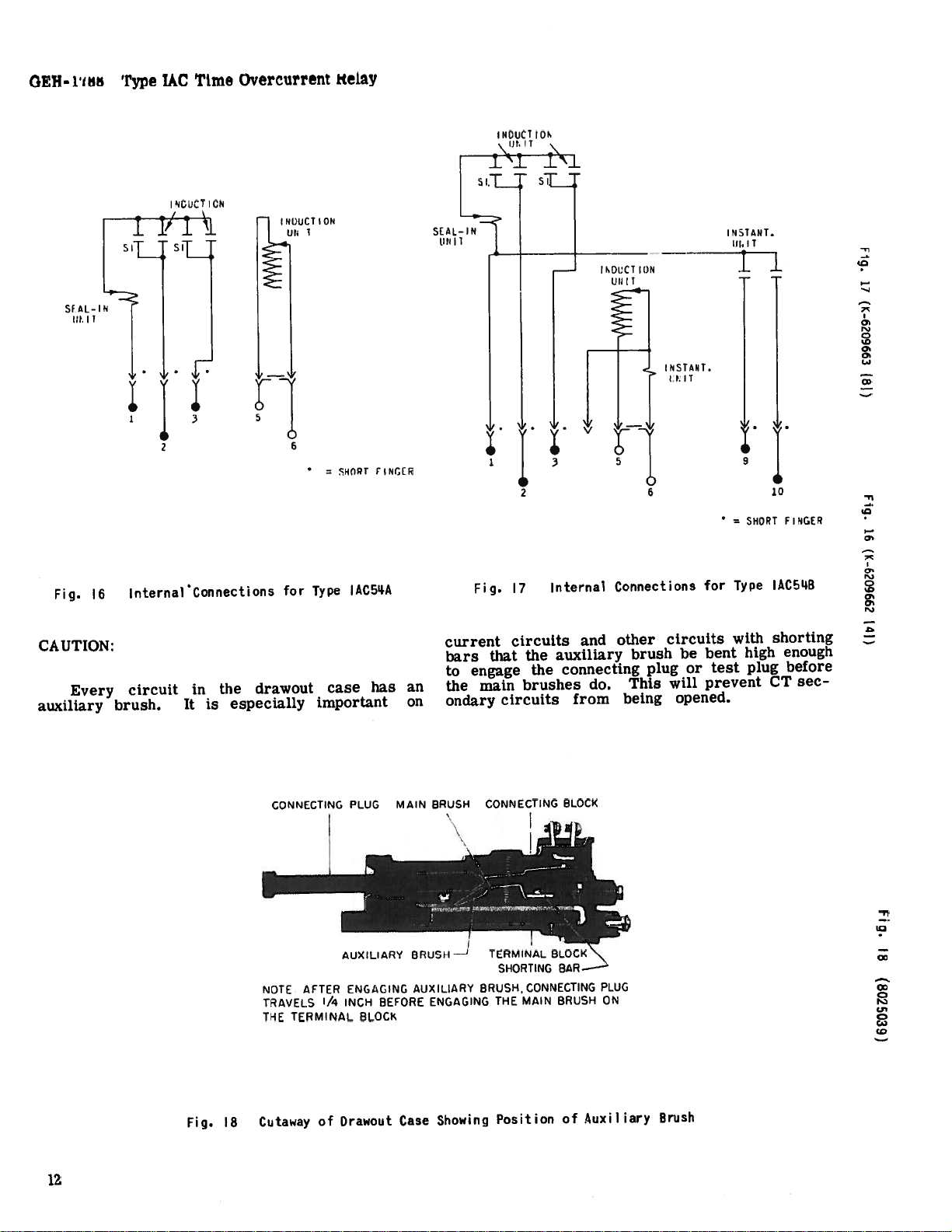
CAUTION:
Every
auxiliary
InternalConnections
circuit
brush.
in
It
the
is
drawout
especially
CONNECTING
NOTE
TRAVELS
THE
for
Type
important
AFTER
TERMINAL
IACSLIA
case
PLUG
AUXILIARY
ENGAGING
)/4
INCH
has
BEFORE
BLOCK
an
on
MAIN
BRUSH---
AUXILIARY
ENGAGING
current
bars
to
the
ondary
BRUSH
17
Fig.
circuits
that
engage
main
circuits
CONNECTING
TERMINAL
SHORTING
BRUSH,
THE
Internal
auxiliary
the
connecting
the
brushes
BLOCK
.i1
BLOCK\
BAR—
CONNECTING
MAIN
BRUSH
and
from
Connections
other
do.
PLUG
ON
brush
This
being
plug
circuits
be
or
will
opened.
for
Type
with
bent
test
prevent
high
plug
IAC5L4B
shorting
enough
before
sec
CT
!•1
L0
CD
CD
U,
Ci)
CD
12
Fig.
18
Cutaway
of
Drawout
Case
Showing
Position
of
Auxiliary
Brush
Page 15

Type
ADJUSTMENTS
JAC
Time
Overcurrent
Relay
GEH-
1788
TARGET
For
from
voltage,
the
0.2-ampere
from
voltage
hand
change
plug.
stationary
Next,
place
necessary
contact
should
0.2
For
2
place
The
stationary
the
Then,
remove
it
in
from
not
trip
to
set
trip
to
tap
contact
the
30
tap
to
INDUCTION
CURRENT
The
be
changed
in
the
tap
plug
current
When
remove
current-transformer
screw
current
The
adjusted
ring
may
around
current
with
the
this
adjustment
also
permits
tween
unit
is
from
within
unit
resets
value.
TIME
The
length
tacts
value.
is
set
must
current
tap
block
firmly
(below
changing
the
the
tap
and
pickup
by
be
the
of
tap
the
various
adjusted
any
time-dial
five
SETTING
setting
of
time
when
The
on
0.
travel
SETTING
by
then
means
turned
edge.
the
per
at
the
contacts
AND
coils
amperes
2.0
the
target
tap.
coils
amperes
the
tap
screw
contact
setting,
take
and
the
left-hand
prevent
getting
in
be
at
changing
at
into
which
connecting
plug
replace
of
by
By
unit
setting
has
any
desired
tap
at
cent
90
per
of
the
current
When
the
maximum
operating
and
operating
screw
is
the
first
a
screw
place
screw
contact.
the
out
both
which
the
the
top
the
tap
the
the
current
plug
secondary
into
tap
the
the
unit
of
a
spring-adjusting
inserting
turning
may
be
employed,
been
disturbed.
settings
the
factory
position
of
the
cent
the
time
unit
requires
reaches
are
just
the
dial
SEAL-IN
on
at
the
seal-in
on
at
the
in
screw
of
the
remove
from
it
in
from
right-hand
of
adjustment.
taps
at
UNIT
the
contacts
position
of
the
marked
unit
is
setting
to
marked
connecting
for
any
a
ring,
the
brought
if
setting
to
to
at
a
tap
of
the
dial
the
closed
is
set
amount
currents
minimum
tap
currents
minimum
the
2-ampere
holding
seal-in
the
the
the
desired
the
other
This
procedure
the
operate
of
the
relay.
for
not
to
short-circuit
circuit.
for
the
plug.
current
tool
in
the
into
for
some
This
intermediate
be
obtained.
close
its
minimum
plug
setting.
minimum
determines
to
close
predetermined
when
on
10,
to
UNIT
ranging
control
screw
ranging
control
the
right-
unit.
connecting
left-hand
tap
stationary
Screws
same
time.
tap
Screw
the
desired
operate).
of
the
unit,
Next,
desired
tap
ring.
the
notches
operating
agreement
reason,
adjustment
contacts
current
closing
its
con
the
the
disk
close
tap.
tap.
and
may
plug
The
be
The
The
the
dial
the
in
To
is
the
the
is
contacts
Imum
The
ation
dial.
moving
shelf;
the
unit
increases
If
required,
circuit
value
insure
several
made
after
unless
accuracy,
whose
EXAMPLE
current
time
required
time-dial
number
to
shown
proper
the
lustrates
where
current
breaker
current
current
minimum
transformer
equals
tap,
time-dial
3750
ratio.
which
ferring
will
current
is
of
of
obtained.
second
secure
set
The
an
the
for
the
The
value
proper
Assume
The
the
amperes,
be
on
accurate
and
time
setting.
primary
of
the
However,
the
permanent
moving
decreases
the
selective
determine
current
for
each
the
proper
circuit
the
relay
circuit
the
there
(at
operation
OF
time
unit can
for
setting
of
times
any
in
Fig.
tap
the
the
circuit
of
approximately
should
of
3750
transformers
current
primary
7.5
amperes.
8-ampere
setting
This
is
7.8
to
the
seen
gives
the
No.
above
dial
therefore
adjustment
unit
further
the
time.
action
of
relay
breakers.
time
contacts
should
the
maximum
is
SETTING
and
be
shown
the
contacts
when
the
of
the
3,
insert
receptacle
position.
procedure
Type
a
breaker
trip
amperes.
tap
ratio.
to
divide
gives
times
time
that
7.8
1.0-second
6
time-dial
results
timing
can
be
is
made
magnet
magnet
the
the
the
line
sequence
involved
time
to
be
current
made
in
the
current-tap
particular
and
The
[AC
in
1.0
setting
tripping
In
this
Since
tap
is
give
62.5
the
current
times
should
device.
made
this
setting
adjustment
toward
time,
of
two
maximum
and
that
differs
in
in
close.
operation
of
dhfference
be
a
current)
selective.
settings
easily
Fig.
to
close
current
the
removable
adjust
following
in
making
relay
should
450
second
of
60/1
is
current
case,
there
used.
1.0-second
3750
amperes
8-ampere
the
time
setting.
until
gives
for
the
by
means
along
the
while
3
Assume
be
moving
or
more
possible
then
the
operation
Allowance
opening
For
between
and
indicates
with
Isaprescribed
setting.
time-current
the
a
is
used
trip
amperes;
on
a
ratio
found
by
by
450
is
To
find
by
the
secondary
petting.
curves
minimum
delay
when
checked
Slight
the
desired
the
time
of
of
the
is
obtained
its
supporting
main
shaft
It
relays
choose
sufficiently
must
each
breaker
this
reason,
is
known
of
about
of
the
quickly.
the
particular
a
In
settings
plug
time-dial
example
relay
setting:
in
circuit
a
on
sustained
a
also,
short-circuit
further
are
dividing
the
current
divided
no
7.5
ampere
the
time
readjustment
proper
delay
transformer
current
By
(Fig.
operating
the
by
means
time
max
oper
time
away
short-
time
a
of
with
relays
over-
Each
time
order
in
that
used.
by
re
3),
relay
by
of
is
to
the
be
0.5
the
to
Il
the
the
60
at
it
is
13
Page 16

GEH-1788
Aid
settings
est
Sales
Select
have
adjustable
head
scale.
locknut
position.
The
about
inch
1/8
loosening
moving
and
IAC
Type
in
may
Office
making
be
the
obtained
the
of
INSTANTANEOUS
current
the
instantaneous
the
is
the
even
To
and
contacts
pole
raise
same
wipe.
the
the
with
turn
screws
piece
lower
or
it
should
time
This
contacts
the
up
Time
General
so
or
and
adjustment
holding
up
Overcurrent
proper
application
on
above
operate
unit
the
that
desired
pole
the
down
be
to
the
down
or
selection
Electric
which
top
calibration
piece,
and
adjusted
have
stationary
Relay
of
the
to
Company.
UNIT
desired
is
and
its
of
loosen
tighten
then
make
to
approximately
made
be
can
as
contacts
required.
relay
near
the
set
hexagon
the
on
the
to
in
at
by
-
-
IIA:3
)
wtN
ç
TE1T
NUICAI
VAN
FLI.G
iTCNG
51
IN’
1_IGIlT
Pri’up
10
INDICATING
CHECKING
SlANT
PICKUP
ANELIL5
LIGHT
o;
IT
UN
N
‘0
The
attention
may
However,
be
tacts.
it
CONTACT
With
should
tension
lie
to
movable
this
Also
pound
ture.
to
bushing
The
allow
open.
adjusted
to
just
armature
of
1/32
the
supporting
edge
ly
contact
ARMATURE
Loosen
assembly
bracket
the
armature
the
core.
about
core.
leaf
1/32
Next,
spring
TRIPPING
A-C
tripping
a-c
other
than
restored
ADJUSTMENT
unit
the
against
always
contact
contact
supported
brass
1/16-inch
a
compound
The
allow
to
touch
the
operates
compound
from
inch
ADJUSTMENT
two
the
bracket
or
in
just
position,
this
In
inch
slide
assumes
unit
occasional
adjustment
the
if
follows:
as
de-energized,
stationary
the
insure
brush
brush
a
should
should
backing
contact
bushing
back
the
brass
open
to
bushing
inner
the
post.
screws
bottom
the
to
whichever
out,
touches
the
the
bracket
from
a
should
good
from
strip
of
backing
the
which
the
the
vertical
cleaning
the
contact
closed
be
the
gap
the
contacts.
should
edge
pole
armature
pole
in
UNIT
not
movable
free
not
top
should
with
support
movable
be
of
hold
of
the
is
face
face
until
require
of
should
with
circuit.
any
of
touch
the
of
be
the
should
when
strip
The
approximate
stationary-
the
armature-
the
frame.
necessary,
of
should
of
the
position
any
the
con
lost,
be
contact
enough
The
kinks.
com
the
arma
adjusted
contacts
contact
outer
Slide
until
upper
the
the
lower
armature
and
be
the
be
is
RFCWU[NDED
L’IN.
RATED
A!
120
FigJ9
spaced
bracket.
the
of
flush
be
should
always
lower
core
alignment
armature
operates
unit
tarily,
breaker
momentary
shock
pole
of
face
cessive
bracket
high
a
during
screws
obtained.
been
I
FR[UENCY
Test
clear
against
enough
put
return
after
is
and
dropping
reclosed.
is
opening
the
when
pressure
being
pickup
operation
securely
10
TM[P
“START”
VOLTS,
Connections
both
of
With
the
flush
it
each
important
pole
may
the
armature
the
pushed
chattering
or
of
after
JAC
of
armature
this
pole
pressure
face
cause
relay
of
lower
the
on
in
the
TO
ACCURATELY
RELAY
ALL
MADE
for
Testing
Relays
setting,
face
against
operation
as
of
the
contacts
target
Under
the
being
coil
armature,
too
unit.
the
and
the
on
the
slight
lower
SHOULD
RELAY
Pickup
armature
both
of
the
pole
of
to
R{PROWCE
IN
the
the
core
open
CHARACTERISTICS
T[STS
WITH
a
when
pulled
is
conditions,
is
in
energized.
these
contacts
caused
will
far,
of
the
movable
Tighten
proper
adjustment
BE
CASE.
Time
&
vertical
cores,
armature
face
unit.
between
gap
after
momen
the
due
against
result
the
Curve
should
and
of
This
circuit
to
Ex
by
in
contact
bracket
tip
to
the
the
the
the
the
the
too
has
The
or
more
one
for
Recommended
are
test
14
pick-up
of
more
or
shown
the
taps
dial
in
current
and
settings.
test
Fig.
should
the
connections
19.
time
be
should
OPERATION
one
be
the
on
checked
above’
checked
for
given
ments
will
factory.
order
Before
a
have
be
to
check
set
It
open
the
is
relay
to
not
zero
at
necessary
the
is
determine
been
relay
into
put
disturbed.
before
to
contacts.
service
that
the
change
factory
The
relay
this
it
leaves
should
adjust-
time
setting
be
dial
the
in
Page 17

Type
MAiNTENANCE
IAC
Time
Overcurrent
Relay
GEH-1788
exploring
The
centered
locked
for
this
burnishing
flexible
surface,
polishing
left,
A.
MAIN
Pickup
Set
minimum
19
the
of
±5%
Time
Set
minimum
19,
and
should
pickup
7.21
seconds
applied
±
7%.
The
jewel
For
yet
tap
Test
operate
current
in
purpose.
strip
resembling
corroded
the
main
the
applying
the
DISK
lower
its
should
in
this
jewel
surface
the
position
AND
air
may
with
be
gaps,
CONTACT
cleaning
tool
action
should
of
is
fine
metal
in
so
delicate
material
ELECTRICAL
UNIT
relay
tap,
value
relay
tap.
operating
unit
Using
at
applied
±7%.
at
Using
should
current.
at
5
1.31
the
the
the
the
times
the
With
time
BEARINGS
be
tested
the
by
point
up
after
the
turned
CLEANING
silver
be
with
effect
5.0
test
seconds
10
used.
a
that
will
0.5
time
test
connections
close
time
connections
pickup
operating
times
should
contacts,
an
be
±7%.
for
cracks
of
a
fine
the
it
should
provided
a
consists
roughened
file.
needle.
disk
flexible
of
The
are
rapidly
until
which
set
screw
This
etched
superfine
no
removed
scratches
ACCEPTANCE
dial
its
contacts
dial
current,
time
pickup
be
position
position
of
the
With
should
0.72
of
Figure
within
Figure
2
times
current
seconds
and
and
relay
be
by
is
be
a
and
thoroughly.
the
cleaning
Fine
knives,
files
deterioration
may
material
standard
checked
may
The
It
files,
leave
is
at
TESTS
B.
INSTANTANEOUS
Pickup
With
pickup
should
pickup
after
C.
Pickup
tap
Dropout
should
of
each
TARGET
The
value
Open
tap
value;
at
be
checks.
unit
remain
of
the
silver
leave
in
burnishing
relay
or
of
minute
the
tool
contacts
abrasive
scratches
the
contacts
PERIODIC
recommended
least
once
gradually
of
±10%
no
more
SEAL
should
the
picked
the
Be
main
unit
test.
with
the
The
actual
contacts.
particles
tool
kit
applied
the
than
sure
IN
pickup
main
unit
should
flexibility
described
obtainable
that
every
UNIT
minimum
UNIT
unit
contacts,
up.
points
should
paper
which
Abrasive
of
and
thus
TESTING
pickup
six
months.
current
variation
±5%
the
target
between
contacts
Reduce
drop
of
the
of
contact.
not
be
or
cloth.
increase
paper
insulating
prevent
is
included
from
of
the
calibration.
has
75
closed.
the
the
current
out.
tool
cleaned
Knives
arcing
abrasive
the
au
unit
on
repeated
been
and
seal
insures
or
cloth
closing.
in
factory.
units
should
There
reset
100%
in
to
with
or
and
the
be
of
unit
25%
renewal
prompt
or
damaged.
It
is
replacement
recommended
parts
be
carried
of
that
any
sufficient
in
stock
that
RENEWAL
quantities
to
are
enable
worn,
broken,
the
PARTS
of
nearest
pany,
the
Parts
When
parts
Sales
specify
by
Bulletin
ordering
Office
the
catalogue
No.
renewal
of
quantity
GEF-3883.
the
numbers
parts,
General
required
as
Electric
and
shown
address
describing
in
the
Com
Renewal
15
Page 18

GEH-l7B
Type
IAC
Time
Overcurrent
Relay
:1/4
4
DRILL
HOLES
1,125
29MM
PANEL
SEMI-FLUSH
MTG.
4)
MTG.
4
406
12MM
LOCATION
10-32
SCREWS
6.187
157MM
SURFACE
MTG.
—
3/9
X
DRILL
5/8
HOLES
2
l5Mi
(2)
FUR
0—32
1
STUDS
-
5/16—18
SURFACE
75
MM
CUTOUT
DRILLED
STUDS
MTG.
NUMBER
97531
00000
00000
8
10
BACK
MAY
156
1.
29MM
STUD
I
‘
6
VIEW
REPLACE
HOLES
NG
2
218.
5MM
FUR
TYPiCAL
INCHES
MM
Fig.
--;---
CUTLUT
•i
5,
14
PANEL
SEMI-FLUSH
DIM.
20
DRILLING
FRONT
(K-6209271
843
72MM
1
687
4MM
MOUNTING
VIEW
181)
VIEW
FUR
Outline
I—
8.812
223MM
CASE
SHOWING
SURFACE
Panel
and
3.0
76MM
ASSEMBLY
MTG.
Drilling
ON
Dimensions
3/4
10
OF
STEEL
5
133MM
DRILL
HOLES
19MM
5/16-18
HARDWARE
PANELS
Relay
for
25
FUR
STUD
Types
PANEL
SURFACE
FRONT
(TYPICAL)
DRILLANG
VIEW
Relays
IAC
.500
12MM
MOUNTING
(11/91)
(200)
GENERAL
ELECTRIC
CO.,
POWER
SYSTEMS
MANAGEMENT
BUSINESS
DEPT..
MALVERN,
PA.
19355
 Loading...