

Page 1
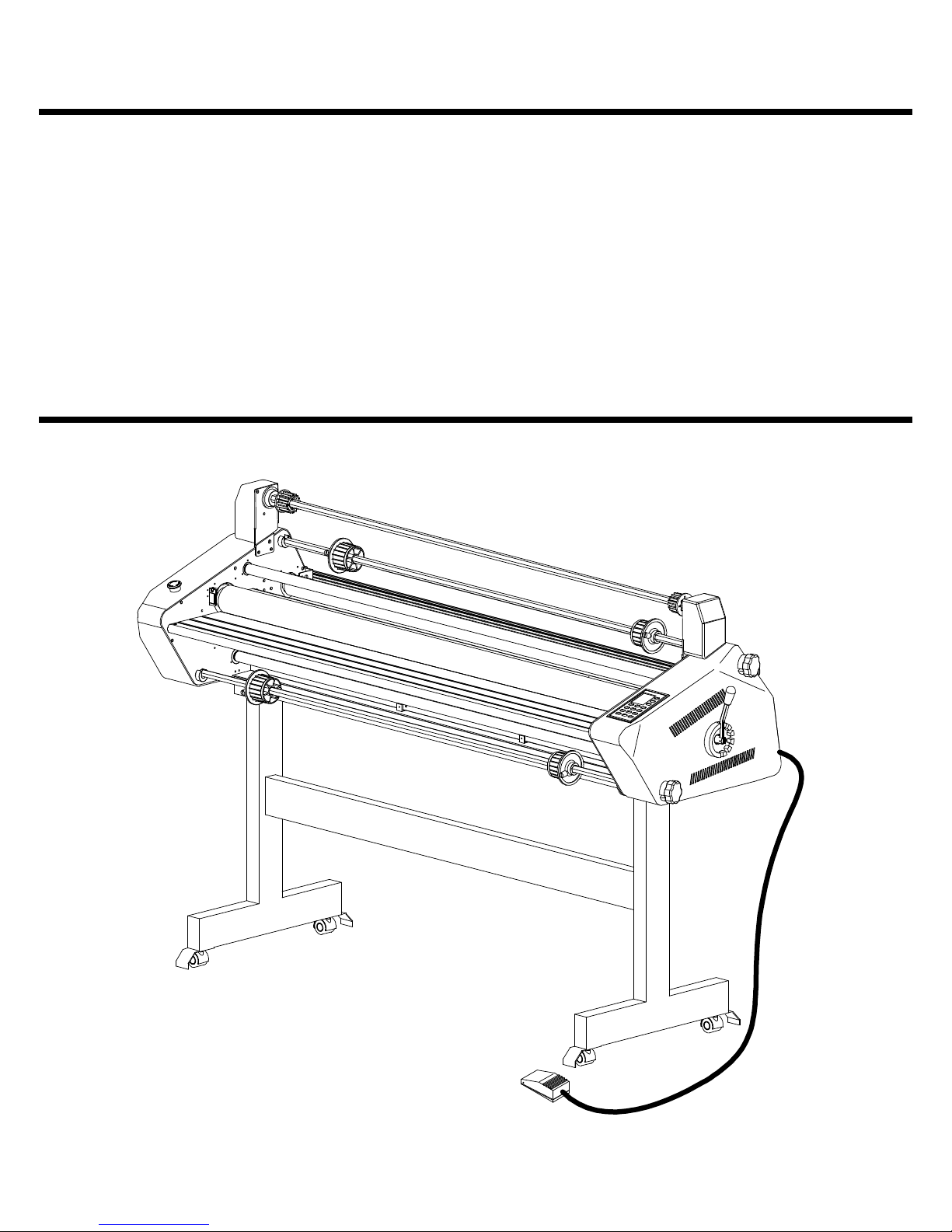
TITAN 110/ 165 OPERATION &
MAINTENANCE MANUAL
© November 2000 GBC Films Group
Do not duplicate without written permission.
GBC Pro - Tech
4151 Anderson Road
DeForest, WI 53532
Revision : B (03/20/03) Ph: ( 608 ) 246 - 8844
Part number : 930 - 046
Fx: ( 608 ) 246 - 8645
Page 2

Read me fileTitan 1 10/ 165 Operation and Maintenance Manual
Read Me File . . . . . . . . .
The information in this publication is provided for reference and is believed to be accurate and complete. GBC Films Group is not liable for errors in this publication or for incidental
or consequential damage in connection with the furnishing or use of the information in this
publication, including, but not limited to, any implied warranty of fitness or merchantability for
any particular use.
GBC Films Group reserves the right to make changes to this publication and to the
products described in it without notice. All specifications and information concerning products
are subject to change without notice.
Reference in this publication to information or products protected by copyright or patent
does not convey any license under the rights of GBC Films Group or others. GBC Films
Group assumes no liability arising from infringements of patents or any other rights of third
parties.
This publication is copyrighted © 2000 by GBC Films Group. All rights reserved. The
information contained in this publication is proprietary and may not be reproduced, stored,
transmitted, or transferred, in whole or in part, in any form without the prior and express written
permission of GBC Films Group.
The following information will explain how to move around within the electronic version
of this publication. The hand will change to a pointer finger identifying hyperlinked areas. When
moving from page to page, use
PAGE, use
from view to view, use
VIEW.
Should you find an error within this publication or would like to make a suggestion,
please utilize the fax correspondence sheet following this read me file and fax it to the number
provided. Your comments and help will ensure up to date information. Thank you.
to go back one PAGE and use to advance one PAGE. When moving
to return to a previous VIEW and use to advance to the next
to return to the first PAGE, use to advance to the last
© GBC Films Group November 2000
Page 3

Read me file Titan 1 10/ 165 Operation and Maintenance Manual
This page intentionally left blank.
© GBC Films Group November 2000
Page 4

Fax Correspondence
Fax number : ( 608 ) 246 - 8645 Date :
To : Sean Flood at GBC Pro-Tech
4151 Anderson Road
DeForest, WI 53532
From :
Company :
Address :
Phone number : ( ) Fax number : ( )
Read me fileTitan 1 10/ 165 Operation and Maintenance Manual
Re : Titan 110/ 165 Operations and Maintenance Manual ( 930046 Rev A )
Section #: Page #:
Correction (s):
Additional comments:
© GBC Films Group November 2000
Page 5

Read me file Titan 1 10/ 165 Operation and Maintenance Manual
This page intentionally left blank.
© GBC Films Group November 2000
Page 6

Section 1: Safety
1.1 Symbols ......................................................................................................1 - 1
1.2 Safety features ............................................................................................1 - 2
1.3 Installation ..................................................................................................1 - 4
1.4 Operations ..................................................................................................1 - 8
T able of ContentsTitan 1 10/ 165 Operation and Maintenance Manual
Table of Contents
1.5 Applications ...............................................................................................1 - 11
1.6 Troubleshooting ........................................................................................1 - 13
1.7 Maintenance ..............................................................................................1 - 13
1.8 Label Explanation .....................................................................................1 - 16
Figure 1.8.1 Label Location ......................................................1 - 17
Section 2: Warranty
2.1 Limited warranty information ....................................................................2 - 1
2.2 Exclusions to the warranty ........................................................................2 - 1
© GBC Films Group November 2000
Page I
Page 7

T able of Contents Titan 1 10/ 165 Operation and Maintenance Manual
Section 3: Specifications
3.1 General .......................................................................................................3 -1
3.2 Consumables................................................................................................3 - 2
3.3 Function ......................................................................................................3 - 3
3.4 Electrical ....................................................................................................3 - 3
3.5 Dimensions .................................................................................................3 - 5
Section 4: Installation
4.1 Pre-installation check list ..........................................................................4 - 1
Figure 4.1.1 Connections Titan 110 ..............................................4 - 2
Figure 4.1.2 Connections Titan 165 - U.S. ....................................4 - 2
Figure 4.1.3 Connections Titan 165 - Europe ...............................4 - 2
Figure 4.1.4 Suggested floor layout- Titan 110............................4 - 3
Figure 4.1.5 Suggested flooer layout- Titan 165 .........................4 - 4
Page II
© GBC Films Group November 2000
Page 8

T able of ContentsTitan 1 10/ 165 Operation and Maintenance Manual
4.2 Know your machine ..................................................................................4 - 5
4.3 Unpacking ..................................................................................................4 - 7
4.4 Shrink wrap ..............................................................................................4 - 7
4.5 Crated .........................................................................................................4 - 8
4.6 Safety check .............................................................................................4 - 10
4.7 Control panel check ..................................................................................4 - 13
4.8 Roller handle .............................................................................................4 - 17
4.9 Film brake adjustment ..............................................................................4 - 18
4.10 Rear cut-off blade ...................................................................................4 - 19
Section 5: Operations
5.1 Control panel .............................................................................................5 - 1
5.2 Emergency .................................................................................................5 - 6
© GBC Films Group November 2000
Page III
Page 9

T able of Contents Titan 1 10/ 165 Operation and Maintenance Manual
5.3 Safety shield ...............................................................................................5 - 3
5.4 Pressure plate .............................................................................................5 - 9
5.5 Feed table .................................................................................................5 - 10
5.6 Film loading ..............................................................................................5 - 11
5.7 Film alignment ..........................................................................................5 - 14
5.8 Change nip ................................................................................................5 - 15
5.9 Rear cut-off ...............................................................................................5 - 16
5.10 Job programming ....................................................................................5 - 17
Section 6: Applications
6.1 Pressure sensitive .......................................................................................6 - 1
6.2 Mounting ....................................................................................................6 - 5
6.3 Encapsulation .............................................................................................6 - 8
Figure 6.1.1 Poly-in/ Poly-out .....................................................6 - 13
Page IV
© GBC Films Group November 2000
Page 10

Section 7: Troubleshooting
7.1 Wave problems ..........................................................................................7 - 1
7.2 Troubleshooting chart ...............................................................................7 - 4
Section 8: Maintenance
T able of ContentsTitan 1 10/ 165 Operation and Maintenance Manual
8.1 Maintenance schedule ...............................................................................8 - 1
8.2 Cleaning the rollers ..................................................................................8 - 2
8.3 Clean the cabinets and covers ....................................................................8 - 7
8.4 Cleaning the control panel .........................................................................8 - 8
© GBC Films Group November 2000
Page V
Page 11

T able of Contents Titan 1 10/ 165 Operation and Maintenance Manual
This page intentionally left blank.
Page VI
© GBC Films Group November 2000
Page 12
Section 1 Safety
CAUTION
Do not attempt to operate your Titan 110/
165 laminator until you have read this
section carefully!
SafetyTitan 110/ 165 Operation and Maintenance Manual
CAUTION
Indicates a potentially hazardous situation
which, if not avoided, could result in minor
or moderate injury, or alerts against unsafe
practices or alerts against actions which
could damage the product.
Your safety, as well as the safety of others, is
important to GBC Films Group. This section contains
important safety information.
The following symbols are used throughout
this manual to indicate Information, Caution,
Warning, Danger and Electrical Shock conditions.
1.1 Symbols
WARNING
Indicates a potentially hazardous situation
which, if not avoided, could result in serious
injury.
DANGER
Indicates an imminently hazardous situation
which, if not avoided, could result in death
or serious injury.
INFORMATION
Indicates helpful information that should be
considered before, during, or after an
action, step or procedure is given.
© GBC Films Group November 2000
ELECTRICAL
SHOCK
Indicates an electrical shock situation which,
if not avoided, could result in serious
paralyzation of the body or death.
Page 1 - 1
Page 13
Safety Titan 110/ 165 Operation and Maintenance Manual
1.2 Safety features
The Titan 110/ 165 laminator has been
designed with safety as a primary consideration;
however, you must become thoroughly familiar with
the controls, proper operation, proper service
procedures and safety features of the laminator before
using or servicing the unit.
In addition, the heating components of the
Titan 1 10/ 165 can reach temperatures of over 200 oF
( 100 oC ).
Qualified ;
• Any engineer that has experience with
electrical and mechanical design of lamination
equipment. The engineers should be fully aware of
all aspects of safety with regards to lamination
equipment.
• Any commissioning or service engineer must
be of competent nature, trained and qualified to GBC
Films Group standards to fulfill that job. This person
will have completed and passed the full service
training course from GBC Films Group.
or GBC Films Group T echnician that has been through
DANGER
At these temperatures there is a danger of
severe burn if the rolls are touched during
setup, operation or servicing.
INFORMATION
Only a qualified service technician should
perform any procedure requiring the
cabinet doors to be opened.
the GBC Pro-Tech service training course.
laminator are the safety latches and the interlocks. The
front safety shield (Figure 1.2.1) and the feed table
(Figure 1.2.2) are both equipped with safety latches.
When a safety latch is not in the locked position, the
motor is disabled.
• Any GBC T echnician, GBC Specialist, and /
An important feature of the Titan 110/ 165
WARNING
The word qualified is defined as;
Page 1 - 2
Caution should always be exercised
when using the laminator with
the safety shields raised.
You can be seriously HURT or INJURED!
© GBC Films Group November 2000
Page 14
SafetyTitan 110/ 165 Operation and Maintenance Manual
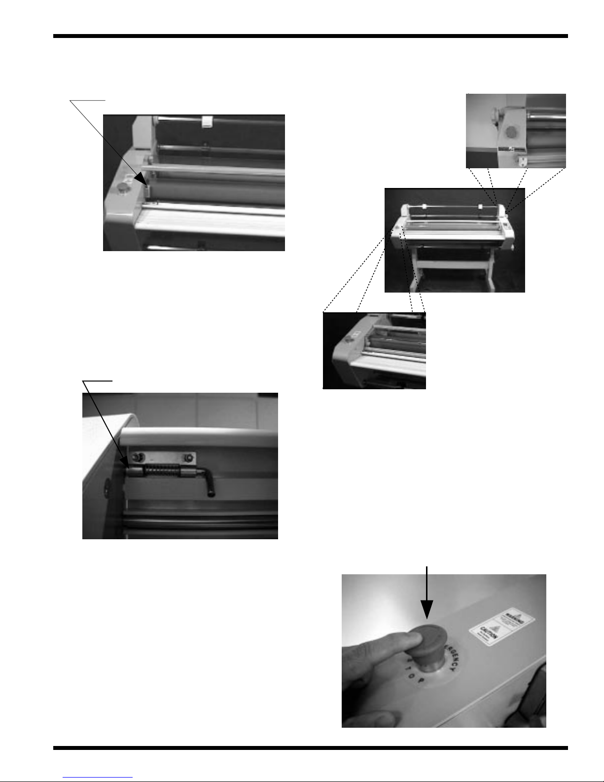
Figure 1.2.1 Safety shield
Safety switch - left and right sides
Figure 1.2.2 Feed table
Figure 1.2.3 Emergency stops
Rear
Table safety pin - left side only
The laminator is equipped with two
EMERGENCY STOPS ( E-STOP ).One is located
on the left side from the front operating position and
the second is located above machine POWER. Refer
to Figure 1.2.3
Front
T o engage the EMERGENCY STOP feature,
press down. Either of these, when engaged, removes
power to the motor.
Press down
© GBC Films Group November 2000
Page 1 - 3
Page 15
Safety Titan 110/ 165 Operation and Maintenance Manual
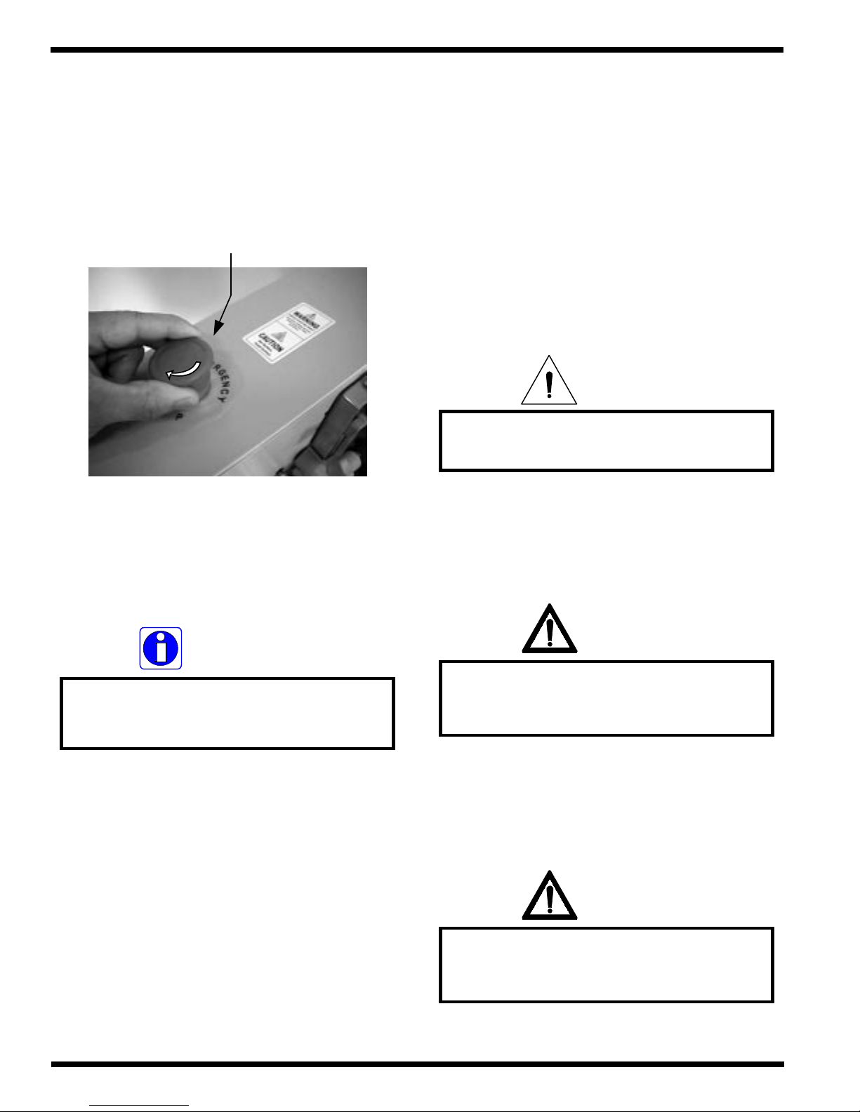
To continue operation, both E-STOPS must
be in the up position. To reset the E-STOP, twist the
button 1/4 turn clockwise.
Rotate 1/4 turn
1.3 Installation
The following symbols are positioned at
various points in Section 4 Installation.
CAUTION
Failure to follow the pre-installation check
list can result in damage to the laminator.
INFORMATION
The laminator will operate only when
all safety latches are in the fully
latched position.
WARNING
The operating environment must be free of
dust, flammable liquids and vapors. You can
be injured by inhaling chemical vapors.
WARNING
Vapor build up or stored flammable liquids
can cause a fire. Excessive dust can damage
the laminator.
Page 1 - 4
© GBC Films Group November 2000
Page 16
SafetyTitan 110/ 165 Operation and Maintenance Manual
CAUTION
Do not locate the laminator where air is
blowing directly on the machine. The air
flow can cool the rollers unevenly and
result in poor quality output.
WARNING
The Titan 110/ 165 Laminator is a large and
heavy piece of equipment. It is necessary to
employ LICENSED R IGGERS ONLY to
move the lam inator. The lam inator is not
de sig n e d to b e tip ped u p or sidew a y s in a n y
way. Such action disturbs the exact
alignment of the rolling parts of the machine
and requ ires extensive realignm en t. You can
be crushed or seriously injured.
INFORMATION
Before signing the Bill of Lading, you should
be sure to inspect the crate and / or pallet
for signs of damage or missing items; if
applicable, make note of this on the Bill of
Lading.
IN F O RM A T ION
Depending on the destination and custom er
preference, the Titan 110/ 165 may be
ship p e d in va rio u s ways . T h e la m in a to r
may arrive shrink wrapped or in a
plywood crate on a skid. Please follow
the unpacking procedure that pertains
to your method of shipm ent.
INFORMATION
ALL SHIPMENTS ARE EX-WORKS.
At our
dock, title passes to the buyer. Please review
your insurance coverage prior to shipment,
as you are responsible for all subsequent
freight charges and risks.
CAUTION
Do not use a knife or other sharp object to
remove the shrink wrap from around the
laminator. You can cause irreparable
damage to the rollers.
WARNING
Do not attempt to move the laminator across
anything other than a flat level surface
without trained and qualified riggers. You
can be crushed or seriously injured.
© GBC Films Group November 2000
Page 1 - 5
Page 17
Safety Titan 110/ 165 Operation and Maintenance Manual
WARNING
The unpacking process requires at least two
people. You can be severely injured, crushed
or cause damage to the laminator.
CAUTION
Do not allow the top to fall into the crate. It
can damage the laminator.
INFORMATION
GBC Films Group's warranty does not
cover malfunction of the equipment due to
mishandling and / or tipping. GBC Films
Group bears no responsibility for personal
injury or damage due to moving the
laminator improperly.
INFORMATION
About recycling: The crate components can
be reused for shipping the laminator again
or can be disassembled and the wood and
screws recycled. The shrink wrap is not
recyclable, so it must be discarded.
INFORMATION
Do not put packing screws on the floor.
They can cause problems when trying to roll
the laminator into position or you can
become injured if stepped on.
servicing the laminator. These items can get
CAUTION
A second person must support the side
labeled 5 in Figure 4.5.1 It can fall and
damage the laminator or cause harm to you
and others.
WARNING
Do not wear ties, loose fitting clothes or
dangling jewelry while operating or
caught in the nip and choke you or you can
be crushed or burned.
WARNING
If a safety feature is not functioning
properly, contact your local service
representative immediately
Page 1 - 6
© GBC Films Group November 2000
Page 18
SafetyTitan 110/ 165 Operation and Maintenance Manual
DANGER
At no time should you attempt to over ride
any of the safety latches on the laminator.
INFORMATION
The laminator will operate only when
all safety latches are in the fully
latched position.
INFORMATION
When any command is pressed on the
control panel, an audible "beep" will
be heard for each increment of
change or each press.
INFORMATION
Top and bottom set points are
intentionally left at 320
o
F
(160 oC) for now.
INFORMATION
Locator pins on the pressure plate are
not associated with an interlock switch.
The laminator can operate without
the pressure plate installed.
WARNING
Caution should always be exercised
when using the laminator with
the safety shields raised.
You can be seriously HURT or INJURED!
WARNING
Keep hands and fingers clear of the
laminator roller nip when changing GAP.
You can be CRUSHED or BURNED!
CAUTION
Never leave the rollers in the down position
without rolling. Prolonged contact in one
area can form flat spots on the rollers.
© GBC Films Group November 2000
Page 1 - 7
Page 19
Safety Titan 110/ 165 Operation and Maintenance Manual
1.4 Operations
WARNING
Extreme caution should always be exercised
working around the core gripper support,
the gripper tabs can cut you!
various points in Section 5 Operations.
WARNING
Caution should always be exercised when
using the rear cut-off blade.
Sharp objects can cut you!
The following symbols are positioned at
WARNING
Do not wear ties, loose fit clothing or
dangling jewelry while operating or
servicing the laminator. These items can get
caught in the nip and choke you or you can
be crushed or burned.
WARNING
Keep hands and fingers away from the
path of the rear cut-off blade.
Sharp objects can cut you!
INFORMATION
The laminator will operate only when
all safety latches are in the fully
latched position.
INFORMATION
Job programming is explained in
Section 5.7
Page 1 - 8
© GBC Films Group November 2000
Page 20
SafetyTitan 110/ 165 Operation and Maintenance Manual
INFORMATION
COOLING
If is illuminated, the cooling fans
are in the "on" position.
INFORMATION
Reverse speed is preset at 1 meter/ minute.
INFORMATION
When an EMERGENCY STOP is engaged,
all motion stops. The nip will not change
from the operating setting.
INFORMATION
When the E-STOP is disengaged, the
rollers will begin turning. By pressing
stop first, The rollers will not turn
until RUN is pressed
INFORMATION
When the set point value is higher than
actual temperature, " WAIT " is indicated
at the bottom of the display.
INFORMATION
When the input value for JOB is
changed, the parameters stored within
that number are displayed.
INFORMATION
The Temperature control panel settings
are not affected when an E-STOP
has been pushed.
WARNING
Caution should always be exercised
when using the laminator with
the safety shields removed.
You can be seriously HURT or INJURED!
© GBC Films Group November 2000
Page 1 - 9
Page 21
Safety Titan 110/ 165 Operation and Maintenance Manual
DANGER
At no time should you attempt to over ride
any of the safety latches on the laminator.
INFORMATION
All E-STOPS must be unlatched, safety
shield fully closed and feed table properly
installed before operating.
WARNING
Extreme caution should always be exercised
working around the 3 inch core grippers,
the gripper tabs can cut you!
CAUTION
Ensure the roll of laminate is loaded
properly on the unwind shaft.
Exposed adhesive should be facing
away from the heated components.
This will prevent hours of cleaning!
INFORMATION
Locator pins on the pressure plate are
not associated with an interlock switch.
The laminator can operate without
the pressure plate installed.
WARNING
Extreme caution should always be exercised
when removing an unwind shaft, the
gripper tabs can cut you!
INFORMATION
For core grippers, turning the roll film in
the same direction as the gripper tabs while
sliding makes loading the film onto
the unwind shaft easier.
WARNING
Keep hands and fingers clear of the
laminator roller nip when changing GAP.
You can be CRUSHED or BURNED!
Page 1 - 10
© GBC Films Group November 2000
Page 22
SafetyTitan 110/ 165 Operation and Maintenance Manual
CAUTION
Never leave the rollers in the down position
without rolling. Prolonged contact in one
area can form flat spots on the rollers.
1.5 Applications
WARNING
Caution should always be exercised when
using the rear cut-off blade.
Sharp blade can cut you!
various points in Section 6 Applications.
WARNING
Keep hands and fingers away from the
bottom of the rear cut-off blade.
Sharp blade can cut you!
The following symbols are positioned at
CAUTION
Stop the laminator before using the rear
cut-off blade. Moving material can
damage the rear cut-off blade!
WARNING
Keep hands and fingers away from the
path of the rear cut-off blade.
Sharp blade can cut you!
WARNING
Do not wear ties, loose fit clothing or
dangling jewelry while operating or
servicing the laminator. These items can get
caught in the nip and choke you or you can
be crushed or burned.
INFORMATION
The Titan 110 is used for illustration
purposes. The procedure is the same
for the Titan 165.
© GBC Films Group November 2000
Page 1 - 11
Page 23
Safety Titan 110/ 165 Operation and Maintenance Manual
CAUTION
Ensure the roll of laminate is loaded
properly on the unwind shaft.
Exposed adhesive should be facing
away from the heated components.
This will prevent hours of cleaning!
WARNING
Caution should always be exercised
when using the laminator with
the safety shields removed.
You can be seriously HURT or INJURED!
INFORMATION
The Titan 110 is used for illustration
purposes. The procedure is the same
for the Titan 165.
INFORMATION
Avoid tacking at the ends first and pressing
towards the center, you may create a tunnel
once you have reached the center. This will
make for a difficult mounting application.
WARNING
Keep hands and fingers clear of the
laminator roller nip when changing GAP.
You can be CRUSHED or BURNED!
INFORMATION
Speed can be increased during operation.
CAUTION
Do not use the rear cut-off blade to
trim the substrate! You can
damage the blade.
CAUTION
Ensure the roll of laminate is loaded
properly on the unwind shaft.
Exposed adhesive should be facing
away from the heated components.
This will prevent hours of cleaning!
Page 1 - 12
© GBC Films Group November 2000
Page 24
1.7 Maintenance
INFORMATION
The temperature may differ with regards
to your laminate. The temperature used
is for instructional purposes only.
various points in Section 8 Maintenance.
SafetyTitan 110/ 165 Operation and Maintenance Manual
The following symbols are positioned at
WARNING
Keep hands and fingers away from
the heat rollers.
You may be BURNED!
INFORMATION
Use the appropriate diagram for the
type of film you are using.
WARNING
Do not wear ties, loose fitting clothes or
dangling jewelry while operating or
servicing the laminator. These items can get
caught in the nip and choke you or you can
be crushed or burned.
INFORMATION
Improper maintenance, can result in
poor output quality.
1.6 Troubleshooting
The following symbols are positioned at
various points in Section 7 Troubleshooting.
© GBC Films Group November 2000
INFORMATION
Below is a recommended maintenance
schedule. Before performing any of the steps
listed, read through the procedures first.
Please follow the instructions pertaining to
the step you are performing.
Page 1 - 13
Page 25
Safety Titan 110/ 165 Operation and Maintenance Manual
ELECTRICAL
SHOCK
Remove power from the laminator before
servicing. You can be severely shocked,
killed or cause a fire.
CAUTION
The following procedure is performed
while the laminator is HOT!
Use extreme caution!
CAUTION
Harden adhesive deposits on the rollers can
cause damage to the rollers.
CAUTION
Do NOT pick or pull heat activated adhesive
off the rolls when they are cold. You can
cause irreparable damage to the
laminating rolls.
WARNING
Heating components are HOT!
You can become severely burned !
CAUTION
Never clean the rollers with sharp or
pointed objects. You may put
irreparable cuts into the rollers.
INFORMATION
The most efficient time to clean the rollers is
after a lamination process is completed.
INFORMATION
The laminator will operate only when
all safety latches are in the fully
latched position.
Page 1 - 14
© GBC Films Group November 2000
Page 26
SafetyTitan 110/ 165 Operation and Maintenance Manual
INFORMATION
If the rolls are heated, proceed to
Removing adhesive build up..
WARNING
Caution should always be exercised
when using the laminator with
the safety shields raised.
You can be seriously HURT or INJURED!
INFORMATION
Rollers only turn in reverse while
depressing .
REVERSE
ELECTRICAL
SHOCK
Do not use liquid or aerosol cleaners on the
laminator. Do not spill liquid of any kind on
the laminator. You can be severely shocked,
killed or cause a fire. Use only a damp cloth
for cleaning unless other wise specified.
CAUTION
Excessive pressure can destroy the silicone
layer by pressing to hard or scrubbing
too long in one spot.
INFORMATION
Locator latches on the pressure plate are
not associated with an interlock switch.
The laminator will operate without
the pressure plate installed.
ELECTRICAL
SHOCK
Do not use liquid or aerosol cleaners on the
laminator. Do not spill liquid of any kind on
the laminator. You can be severely shocked,
killed or cause a fire. Use only a damp cloth
for cleaning unless other wise specified.
© GBC Films Group November 2000
Page 1 - 15
Page 27
Safety Titan 110/ 165 Operation and Maintenance Manual
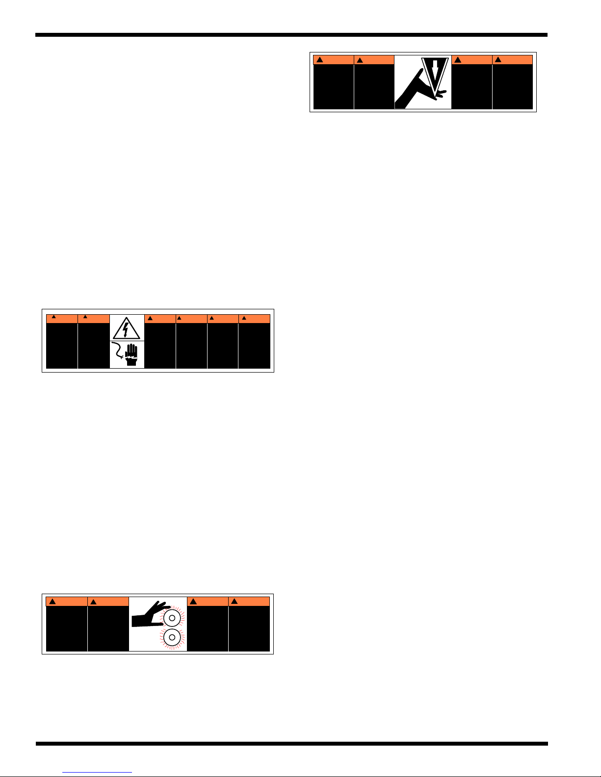
1.8 Label Explanations
Posted at various locations on the Titan 110/
165 Laminator are important safety labels. Pay
careful attention to these labels at all times! Figure
1.8.1 illustrates the location of each of these labels.
!
Riesgo de
choque
electrico
No abra
Adentro, no hay
piezas
reparables
para el usuario.
Mantenimiento
solamente para
personal
calificado
MUCHO
CUIDADO
!
MUCHO
CUIDADO
Risque de
secousse
electrique.
Ne pas ouvrir.
Pas de pieces
reparables par
l'utilisateur.
Entretien par
personnel
qualifie.
WARNING!WAARSCHUWING!ATTENZIONE!WARNUNG
Electrical shock
hazard.
Do not open.
No user
serviceable
parts inside.
Refer servicing to
qualified service
personnel.
Kans op
elektrische
schok.
Niet openen
Bevatgeen door
gebruik te
repareren
onderdelen.
Door bevoegd
service
personeel
laten repareren
Pericolo di
scarica
elettrica.
Nessuna parte
riparabile
dall' utente.
Chiamare un
servizio
di riparazioni
qualificato.
!
SpannungsfUhren
de
Teile.
Nicht offnen.
Enthalt keine vom
Enduerbraucher zu
wartende Teile.
Fur service bitte an
qualifiziertes
Service-Personal
wenden.
!
CUIDADO
NAVAJA FILOSA.
Mantener manos y
dedos a distancia.
!
ATTENTION
LAME COUPANTE.
Tenir mains et
doigts a l'ecant.
CAUTION!WARNUNG
SHARP BLADE.
Keep hands and
clothing away.
!
SCHAREE KLINGE
Hande und finger
ferhalten.
( 1 ) SHARP BLADE: Sharp blade comes down.
Keeps hands and fingers away .
( 3 ) ELECTRICAL SHOCK: Electrical shock
hazard. Electrical voltage behind panel.
!
CUIDADO
RODILLOS
CALIENTES.
PUNTO DE
PINCHAMIENTO.
Mantener manos y
ropa a distancia.
ATTENTION
!
ROULEAUX
CHAUDS.
POINT DE
PINCEMENT.
Tenir mains et
vetements a l'ecant.
CAUTION
!
HOT ROLLS.
PINCH POINT.
Keep hands and
clothing away.
WARNUNG
!
HEISSE
ROLLEN
Klemmgefahr
zwischen Rollen
Hande und
Kleidung ferhalten
( 2 ) Roller Pinch Point: Keep hands and fingers
away . You may be crushed and/ or burned.
Page 1 - 16
© GBC Films Group November 2000
Page 28
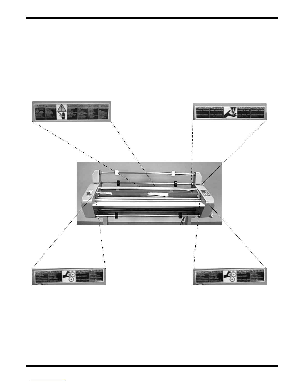
Figure 1.8.1 Label placement
SafetyTitan 110/ 165 Operation and Maintenance Manual
Rear, below rear cut-off guide
Rear, right side cabinet
Frame, left side from front Frame, right side from front
© GBC Films Group November 2000
Page 1 - 17
Page 29

Safety Titan 110/ 165 Operation and Maintenance Manual
This page intentionally left blank.
Page 1 - 18
© GBC Films Group November 2000
Page 30

Section 2 Warranty
GBC Films Group warrants the equipment sold
is free from defects in material and workmanship for a
period of one ( 1 ) year parts and 90 days labor from
the date of installation. This warranty is the only warranty
made by GBC Films Group and connot be modified or
amended.
GBC Films Group’s sole and exclusive
liability and the customer’s sole and exclusive
remedy under this warranty shall be, at GBC Films
Group’s option, to repair or replace any such
defective part or product. These remedies are only
available if GBC Films Group’s examination of the
product discloses to GBC Films Group’ s satisfaction
that such defects actually exist and were not caused
by misuse, neglect, attempt to repair , unauthorized
alteration or modification, incorrect line voltage, fire,
accident, flood, or other hazard.
WarrantyTitan 1 10/ 165 Operation and Maintenance Manual
CAUTION
Unauthorized customer alterations will
void this warranty.
THE WARRANTY MADE HEREIN IS IN
LIEU OF ALL OTHER WARRANTIES,
EXPRESS OR IMPLIED, INCLUDING
ANY WARRANTY OR
MERCHANTABILITY OR FITNESS
FOR A PARTICULAR PURPOSE. GBC
PRO-TECH WILL NOT BE LIABLE
FOR PROPERTY DAMAGE OR
PERSONAL INJURY ( UNLESS
PRIMARILY CAUSED BY ITS
NEGLIGENCE ), LOSS OF PROFIT OR
OTHER INCIDENTAL OR
CONSEQUENTIAL DAMAGES
ARISING OUT OF THE USE OR
INABILITY TO USE THE EQUIPMENT.
2.1 Limited Warranty
This warranty specifically does not cover damage
to the laminating rollers caused by knives, razor blades,
other sharp objects, failure caused by adhesives or
improper use of the machine. Warranty repair or
replacement does not extend the warranty beyond the
initial one year period from the date of delivery .
© GBC Films Group November 2000
2.2 Exclusions to the
Warranty
This warranty specifically does not
cover;
1. Damage to the laminating rolls caused by
knives, razor blades, other sharp objects or
failure caused by adhesives.
Page 2 - 1
Page 31

Warranty Titan 110/ 165 Operation and Maintenance Manual
2. Damage to the machine caused by lifting, tilting
and/or any attempt to position the machine other
than rolling on the installed castors on even
surfaces.
3. Improper use of the machine.
4. Damage due from unqualified person(s) servicing the
machine.
Qualified
• Any engineer that has experience with
electrical and mechanical design of lamination
equipment.The engineers should be fully aware of all
aspects of safety with regards to lamination equipment.
• Any commissioning or service engineer must
be of competent nature, trained and qualified to GBC
Pro-T ech standards to fulfill that job. This person will
have completed and passed the full service training
course from GBC Pro-T ech.
• Any GBC T echnician, GBC Specialist, and /
or GBC Pro-T ech Technician that has been through the
GBC Pro-T ech service training course.
Page 2 - 2
© GBC Films Group November 2000
Page 32

Section 3: Specifications
Specifications provide all of the technical data
for the Titan 1 10/ 165 Laminator. All specifications refer
to both the Titan 1 10 and Titan 165, U.S. and Europe,
unless otherwise specified.
Section 3.1 General
SpecificationsTitan 1 10/ 165 Operation and Maintenance Manual
Description:
Features:
Applications:
• A high speed laminator for the graphic arts professional
as well as the manufacturer who produces promotional
pieces in-house. A laminator with elegant design, low
power consumption and first class safety and quality
assurances.
• Roller heating technology
• Independent control of each heat roller
• Thermal and cold lamination capabilities
• Unique vented cooling system
• Mounting capabilites up to 1/2 in. ( 1.3 cm ) thickness
• Easy to use computer interface control panel
• 9 Programmable job locations
• LCD temperature displays for each heating surface
• Rear output cut-off blade
• Encapsulation - Promotional materials, posters,
counter cards, POP displays, calendars,
instructional displays, phone/ debit cards,
blueprints, menus, placemats, maps, flipcharts, etc.
Page 3 - 1 © GBC Films Group November 2000
Page 33

Specifications Titan 1 10/ 165 Operation and Maintenance Manual
Section 3.2 Consumables
Film types:
Film diameters:
Core Size:
Film widths
Titan 165:
• Poly-in films, thermal and pressure sensitive
• Poly-out films, thermal and pressure sensitive
• Up to a 7 in. outside roll diameter ( 18 cm )
• 2-1/4 in. adapters included ( 57 mm )
• 3 in. core standard ( 76 mm )
• 61 in. Thermal films ( 155 cm )
• 62 in. Pressure sensitive films ( 157 cm )
Paper widths
Titan 110:
Titan 165:
Titan 110:
• 42 in. maximum paper width ( 107 cm )
• 42 in. Pressure sensitive films ( 107 cm )
• 62 in. maximum paper width ( 155 cm )
• 42 in. maximum paper width ( 107 cm )
Page 3 - 2 © GBC Films Group November 2000
Page 34

Section 3.3 Function
Speed:
SpecificationsTitan 1 10/ 165 Operation and Maintenance Manual
U.S.
Europe
Motor:
Heating capabilities:
Controls:
Roll design:
• 0 - 10 fpm ( 0 - 3 m / min )
• 0 - 5 fpm ( 0 - 1.5 m / min )
• DC Gear motor
• Up to 320 oF ( 160 oC )
• Operations control panel
• High release silicone nip rollers
• High release silicone pull rollers
Section 3.4 Electrical
Requirements
Titan 165:
Titan 165 Europe:
Titan 1 10:
Titan 1 10 Europe:
• 230 - 240 V AC, 60 Hz, single phase, 30 amps.
• 230 - 240 VAC, 50 Hz, Single phase, 15 amps.
• 230 - 240 V AC, 60 Hz, single phase, 20 amps.
• 230 - 240 VAC, 50 Hz, Single phase, 15 amps.
Page 3 - 3 © GBC Films Group November 2000
Page 35

Specifications Titan 1 10/ 165 Operation and Maintenance Manual
B.T .U. output
Titan 165: U.S.
Titan 1 10:
Heater wattages
Titan 165: U.S.
Titan 1 10:
Europe
Europe
• 30708 B.T .U. / hour
• 22519 B.T .U. / hour
• 20472 B.T .U. / hour
• 4500 W/ heater
• 3300 W/ heater
• 3000 W/ heater
Amperage draw
Titan 165: U.S.
Titan 1 10:
D/C Voltage used:
Europe
• Drive motor = 3.3 amps
• Fan motor = 0.5 amps
• Motors and heaters = 25 amps
• Drive motor = 3.3 amps
• Fan motor = 0.5 amps
• Motors and heaters = 13 amps
• Drive motor = 3.3 amps
• Fan motor = 0.5 amps
• Motors and heaters = 12 amps
• 36 vdc motor voltage
• 24 vdc fan motor
A/C V oltage used:
Page 3 - 4 © GBC Films Group November 2000
• 230 vac ( minimum )
Page 36

Section 3.5 Dimensions
Weight
SpecificationsTitan 110/ 165 Operation and Maintenance Manual
Titan 165:
Titan 110:
Dimensions (W x L x H)
Titan 165:
• Machine only : 591 lbs. ( 268 kgs. ) (Rev. B)
• Shipping : 999 lbs. ( 453 kgs. ) (Rev. B)
• Gross weigth/ volume : 1201 lbs. (545 kgs.) (Rev. B)
• Machine only : 463 lbs. ( 210 kgs. ) (Rev. B)
• Shipping : 756 lbs. ( 343 kgs. ) (Rev. B)
• Gross weigth/ volume : 941 lbs. (427 kgs.) (Rev. B)
• Machine: 77.25 in. x 25.5 in. x 49 in.
(196 cm x 57 cm x 124 cm)
• Shipping: 87 in. x 39 in. x 59 in. (Rev. B)
(221 cm x 99 cm x 150 cm) (Rev. B)
Titan 110:
Nip Height:
• Machine: 57.25 in. x 25.5 in. x 49 in.
(145 cm x 57 cm x 124 cm)
• Shipping: 68 in. x 39 in. x 59 in. (Rev. B)
(173 cm x 99 cm x 150 cm) (Rev. B)
• 35.50 in. (90 cm)
Page 3 - 5 © GBC Films Group November 2000
Page 37

Specifications Titan 1 10/ 165 Operation and Maintenance Manual
This page intentionally left blank.
Page 3 - 6 © GBC Films Group November 2000
Page 38

InstallationTitan 1 10/ 165 Operation and Maintenance Manual
Section 4 Installation
GBC Films Group is committed to a program of
ongoing product improvement. As a result, we are
providing these instructions so that you can insure that
your new Titan 1 10/ 165 Laminator is properly and securely
unpacked, moved, and installed.
Before a Titan 110/ 165 Laminator can be
installed, there are a few requirements that must be met.
Make certain that each of the requirements listed in the
following pre-installation checklist are met before beginning
installation.
Is the enviroment appropriate for the laminator?
The laminator requires a clean, dust and vapor
free enviroment to operate properly . It must not
be located where there is air blowing directly on
the machine.
Have you contatced a certified electrician to install
a receptacle for the laminator and ensure that
adequate power is being supplied, having the the
appropriate capacity , over current protection and
safety lockouts are available?
WARNING
CAUTION
Failure to follow the pre-installation check
list can result in damage to the laminator.
4.1 Pre-installation
Are the doorways and hallways wide enough for
the the laminator to be moved to the installation
site?
Is there ample room for the laminator?
The operating environment must be free of
dust, flammable liquids and vapors. You can
be injured by inhaling chemical vapors.
WARNING
Vapor build up or stored flammable liquids
can cause a fire. Excessive dust can damage
the laminator.
A work area must be established that allows for
unrestricted movement around the laminator and
provides space for efficient material flow . Figure
4.1.4 and Figure 4.1.5 illustrates a typical machine
area layout.
© GBC Films Group November 2000
CAUTION
Do not locate the laminator where air is
blowing directly on the machine. The air
flow can cool the rollers unevenly and
result in poor quality output.
Page 4 - 1
Page 39

Installation Titan 1 10/ 165 Operation and Maintenance Manual
U.S. and Canada: The laminator requires 220
to 240 vac, 60 hz, ( Titan 165 - 30 amps) or
( Titan 1 10 - 20 amps ), single phase.
Europe: The laminator requires 220 to 240 vac,
50 hz, 20 amps ( 110 & 165 ), single phase
WARNING
The Titan 110/ 165 Laminator is a large and
heavy piece of equipment. It is necessary to
employ LICENSED R IGGERS ONLY to
move the lam inator. The lam inator is not
de sig n e d to b e tip ped u p or sidew a y s in a n y
way. Such action disturbs the exact
alignment of the rolling parts of the machine
and requ ires extensive realignm en t. You can
be crushed or seriously injured.
Figure 4.1.2 Connections - Titan 165
U.S.
30A - 250V
OR
50A - 250V
NEMA 6 - 30P
NEMA 6 - 30R
Figure 4.1.3 Connections - Titan 165
Europe
Figure 4.1.1 Connections - Titan 110
NE M A 6 - 20P NE M A 6 - 20R
Page 4 - 2
15A receptacle
15A plug
© GBC Films Group November 2000
Page 40

Figure 4.1.4 Suggested Floor Layout - Titan 110
4' x 6' ( 1.22 m x 2m )
Work table on wheels
8.94 ft.
( 2.72 m )
Table height
35-3/4" ( .94 - .95m )
57.25 "
( 145 cm )
InstallationTitan 1 10/ 165 Operation and Maintenance Manual
20 ft.
( 6.1 m )
25.5 in.
( 65 cm )
8.94ft.
( 2.72m )
3' ( 1 m)
4' x 6' ( 1.22 m x 2m )
Work table on wheels
Table height
35-3/4" ( .94 - .95m )
© GBC Films Group November 2000
13' ( 4 m)
Page 4 - 3
Page 41

Installation Titan 1 10/ 165 Operation and Maintenance Manual
Figure 4.1.5 Suggested Floor Layout - Titan 165
4' x 6' ( 1.22 m x 2m )
Work table on wheels
8.94 ft.
( 2.72 m )
Table height
35-3/4" ( .94 - .95m )
77.25 "
( 196 cm )
20 ft.
( 6.1 m )
25.5 in.
( 65 cm )
8.94ft.
( 2.72m )
3' ( 1 m)
4' x 6' ( 1.22 m x 2m )
Work table on wheels
Table height
35-3/4" ( .94 - .95m )
Page 4 - 4
13' ( 4 m)
© GBC Films Group November 2000
Page 42

InstallationTitan 1 10/ 165 Operation and Maintenance Manual
4.2 Know your machine
Before performing any procedure within this
manual, it is recommended that you take time to know
the parts of your new machine.
Figure 4.2.1 Sides of the laminator
Front
Figure 4.2.2 Safety
Shield latch Right cabinetLeft cabinet
E-STOP
ON/ OFF
Safety
shield
Table latch
Rear
Right Left
Figure 4.2.3 Rollers
Upper main roller
Lower main roller
© GBC Films Group November 2000
Upper pull roller
Lower pull roller
Page 4 - 5
Page 43

Installation Titan 1 10/ 165 Operation and Maintenance Manual
Figure 4.2.4 Idlers and shafts
Upper web idler
Upper unwind shaft
Lower unwind shaft
Feed table bar
Figure 4.2.6 Right side
Upper unwind
brake adjust
Rewind shaft
Main roller
nip handle
Lower unwind
brake adjust
Lower web idler
Figure 4.2.5 Hardware
Core ends
Pressure plate Control panel
Figure 4.2.7 Miscellaneous
Rewind drive
Shaft saddle
Brake assembly
Footswitch
Power cord Feed table
Core grippers
Page 4 - 6
© GBC Films Group November 2000
Page 44

InstallationTitan 1 10/ 165 Operation and Maintenance Manual
4.3 Unpacking
INFORMATION
ALL SHIPMENTS ARE EX-WORKS.
dock, title passes to the buyer. Please review
your insurance coverage prior to shipment,
as you are responsible for all subsequent
freight charges and risks.
INFORMATION
At our
4.4 Shrink Wrapped
a) Inspect the machine for any obvious shipping
damages upon receipt.
b) Carefully unwrap the shrink wrap from around
the laminator .
Before signing the Bill of Lading, you should
be sure to inspect the crate and / or pallet
for signs of damage or missing items; if
applicable, make note of this on the Bill of
Lading.
IN F O RM A T ION
Depending on the destination and custom er
preference, the Titan 110/ 165 may be
ship p e d in va rio u s ways . T h e la m in a to r
may arrive shrink wrapped or in a
plywood crate on a skid. Please follow
the unpacking procedure that pertains
to your method of shipm ent.
CAUTION
Do not use a knife or other sharp object to
remove the shrink wrap from around the
laminator. You can cause irreparable
damage to the rollers.
c) With another person, carefully wheel your
Titan 1 10/ 165 Laminator to the installation site.
With regards to your shipping methods, use one
of the following procedure described to safely and
properly unwrap / uncrate your laminator .
© GBC Films Group November 2000
WARNING
Do not attempt to move the laminator across
anything other than a flat level surface
without trained and qualified riggers. You
can be crushed or seriously injured.
Page 4 - 7
Page 45

Installation Titan 1 10/ 165 Operation and Maintenance Manual
4.5 Crated
INFORMATION
Do not put packing screws on the floor.
They can cause problems when trying to roll
the laminator into position or you can
WARNING
The unpacking process requires at least two
people. You can be severely injured, crushed
or cause damage to the laminator.
become injured if stepped on.
CAUTION
Tools required
• # 2 Phillips head screwdriver
• Large adjustable wrench
• Crow bar
• A second person
To uncrate the laminator
a) Remove the top of the crate and then the sides
in the order shown in Figure 4.5.1
A second person must support the side
labeled 5 in Figure 4.5.1 It can fall and
damage the laminator or cause harm to you
and others.
Figure 4.5.1 Disassembling of the crate
1
3
5
CAUTION
Do not allow the top to fall into the crate. It
can damage the laminator.
Page 4 - 8
4
2
© GBC Films Group November 2000
Page 46

Removing the shrink wrap
InstallationTitan 1 10/ 165 Operation and Maintenance Manual
WARNING
a) Gently unwrap the shrink wrap from around the
laminator.
CAUTION
Do not use a knife or other sharp object to
remove the shrink wrap from around the
laminator. You can cause irreparable
damage to the rollers.
Moving the laminator
The Titan 110/ 165 Laminator is a large and
heavy piece of equipment. It is necessary to
employ LICENSED R IGGERS ONLY to
move the lam inator. The lam inator is not
de sig n e d to b e tip ped u p or sidew a y s in a n y
way. Such action disturbs the exact
alignment of the rolling parts of the machine
and requ ires extensive realignm en t. You can
be crushed or seriously injured.
INFORMATION
GBC Films Group's warranty does not
cover malfunction of the equipment due to
mishandling and / or tipping. GBC Films
Group bears no responsibility for personal
injury or damage due to moving the
laminator improperly.
a) Have the laminator lifted off the skid and
placed on the floor by licensed riggers.
WARNING
Do not attempt to move the laminator across
anything other than a flat level surface
without trained and qualified riggers. You
can be crushed or seriously injured.
© GBC Films Group November 2000
b) Remove any plastic strapping and/or packing
paper taped to the machine.
CAUTION
Do not use a knife or other sharp object to
remove the shrink wrap from around the
laminator. You can cause irreparable
damage to the rollers.
Page 4 - 9
Page 47

Installation Titan 1 10/ 165 Operation and Maintenance Manual
c) Move all packing materials to a safe distance
from the laminator and dispose of properly .
d) Use two people to carefully roll the laminator to
the desired location.
INFORMATION
About recycling: The crate components can
be reused for shipping the laminator again
or can be disassembled and the wood and
screws recycled. The shrink wrap is not
recyclable, so it must be discarded.
4.6 Safety check
and interlock switches are functioning properly .
The safety check will ensure that all safety devices
WARNING
Do not wear ties, loose fitting clothes or
dangling jewelry while operating or
servicing the laminator. These items can get
caught in the nip and choke you or you can
be crushed or burned.
e) Use Figure 4.1.1 for the suggested floor
layout and plug the laminator into the proper
receptacle outlet.
WARNING
If a safety feature is not functioning
properly, contact your local service
representative immediately
DANGER
At no time should you attempt to over ride
any of the safety latches on the laminator.
Page 4 - 10
© GBC Films Group November 2000
Page 48

InstallationTitan 1 10/ 165 Operation and Maintenance Manual
Feed table
INFORMATION
The laminator will operate only when
all safety latches are in the fully
latched position.
a) Press POWER to “ I ” .
On/ Off
c) Press
d) Under the left side of the feed table, slide the
safety latch to the right. Bottom rollers stop.
RUN
.
c) Press SPEED to “ 5 ”.
© GBC Films Group November 2000
e) Release the safety latch, the bottom rollers
revert to turning.
INFORMATION
Locator pins on the pressure plate are
not associated with an interlock switch.
The laminator can operate without
the pressure plate installed.
Page 4 - 11
Page 49

Installation Titan 1 10/ 165 Operation and Maintenance Manual
Front safety shield
WARNING
Caution should always be exercised
when using the laminator with
the safety shields raised.
You can be seriously HURT or INJURED!
a) Raise the front safety shield. Bottom rollers
stop.
Emergency stops
a) Press the front emergency stop ( E-STOP )
down. The bottom rollers stop turning.
b) Lower the front safety shield to its fully closed
position, the bottom rollers revert to turning.
INFORMATION
b) Rotate the E-STOP clockwise to reset. The
bottom rollers revert to turning
The laminator will operate only when
all safety latches are in the fully
latched position.
Page 4 - 12
c) Repeat steps “a” and “b” for the rear E-STOP.
© GBC Films Group November 2000
Page 50

InstallationTitan 1 10/ 165 Operation and Maintenance Manual
4.7 Control panel check
The control panel should be checked to ensure
all controls function properly .
For a detailed explanation of the control panel
and footswitch refer to Section 5 Operations.
b) Press
STAND-BY
. The display indicates AUTO-
OFF mode in the lower right corner .
c) Press
STAND-BY
again. The display indicates
READY mode in the lower left corner .
INFORMATION
When any command is pressed on the
control panel, an audible "beep" will
be heard for each increment of
change or each press.
a) Press POWER to “ I ” .
On/ Off
d) Press
MEMORY
MEMORY
. An audible beep is heard.
is explained in Section 5 Operations
© GBC Films Group November 2000
Page 4 - 13
Page 51

Installation Titan 1 10/ 165 Operation and Maintenance Manual
e) Press
f) Press
COOLING
. The fans turn on.
COOLING
a second time. The fans turn off.
h) Press SPEED . Numeric value for
SPEED increases with a maximum setting of
9. The rollers increase in speed with each
increment
i) Press SPEED . Numeric value for
SPEED decreases with a minimum setting of
1. The rollers decrease in speed with each
increment
g) Press
RUN
. The bottom rollers begin turning
towards the rear of the laminator.
Page 4 - 14
j) Press
STOP
. The bottom rollers stop turning.
© GBC Films Group November 2000
Page 52

InstallationTitan 1 10/ 165 Operation and Maintenance Manual
k) Press
RUN
. The bottom rollers begin turning
towards the front of he machine.
n) Press BOTTOM TEMPERA TURE .
Numeric value increases with a maximum
setting of 320 oF ( 160 oC ).
l) Once confirmed, release. The bottom rollers
stop turning in a reverse direction.
m) Press TOP TEMPERA TURE .
Numeric value increases with a maximum
setting of 320 oF ( 160 oC ).
INFORMATION
Top and bottom set points are
intentionally left at 320
o
F
(160 oC) for now.
o) Press JOB . Numeric value for JOB
increases with a maximum setting of 9.
© GBC Films Group November 2000
Page 4 - 15
Page 53

Installation Titan 1 10/ 165 Operation and Maintenance Manual
p) Press JOB . Numeric value for JOB
decreases with a maximum setting of 1.
WARNING
Caution should always be exercised
when using the laminator with
the safety shields raised.
You can be seriously HURT or INJURED!
r) Lower the front safety shield to its fully closed
position.
INFORMATION
The laminator will operate only when
all safety latches are in the fully
latched position.
s) Press T OP TEMPERATURE then
BOTTOM TEMPERA TURE .
Numeric values decrease with a minimum
setting of 32 oF ( 0 oC ).
q) Raise the front safety shield and touch the upper
and lower main rollers. They should feel warm
to the touch.
Page 4 - 16
© GBC Films Group November 2000
Page 54

4.8 Roller handle
The roller handle raises and lowers the main rollers
and the pull rollers simultaneously . The roller handle guide
is notched with preset nip heights. The roller handle is
located on the right side of the laminator.
WARNING
InstallationTitan 1 10/ 165 Operation and Maintenance Manual
CAUTION
Never leave the rollers in the down position
without rolling. Prolonged contact in one
area can form flat spots on the rollers.
b) Rotate the handle towards the front of the
machine. The upper main roller and the upper
pull roller raise up.
Keep hands and fingers clear of the
laminator roller nip when changing GAP.
You can be CRUSHED or BURNED!
a) Pull the handle away from the notch and rotate
toward the rear of the machine. The upper main
roller and the upper pull roller lowers.
© GBC Films Group November 2000
Page 4 - 17
Page 55

Installation Titan 1 10/ 165 Operation and Maintenance Manual
4.9 Film brake adjustment
Perform each of the following steps for
the upper and lower unwind shafts while standing to the
right of the front operating position.
Illustrations are for the upper unwind. The lower
unwind is identical to the upper unwind with the exception
of the saddle for the film brake adjustment assembly .
- As you turn the film brake adjustment dial, you
feel an increase in resistance while turning the
unwind shaft.
b) Rotate the unwind shaft while turning the film
brake adjustment dial counter clockwise.
WARNING
Extreme caution should always be exercised
working around the core gripper support,
the gripper tabs can cut you!
a) Use one hand to rotate the unwind shaft while
the other hand is turning the film brake
adjustment dial clockwise with the other hand.
- As you turn the film brake adjustment dial, you
feel a decrease in resistance while turning the
unwind shaft.
c) Perform the same steps for the lower unwind
shaft and brake.
Page 4 - 18
© GBC Films Group November 2000
Page 56

InstallationTitan 1 10/ 165 Operation and Maintenance Manual
4.10 Rear cut-off blade
WARNING
Caution should always be exercised when
using the rear cut-off blade.
Sharp objects can cut you!
WARNING
b) Release the rear cut-off blade tab. The blade
retracts into the housing.
Keep hands and fingers away from the
path of the rear cut-off blade.
Sharp objects can cut you!
a) Press down on the rear cut-off blade tab. The
blade should extend from the housing smoothly .
c) Gently slide the rear cut-off blade from one side
of the laminator to the other side. The
movement should be smooth.
© GBC Films Group November 2000
Page 4 - 19
Page 57

Installation Titan 1 10/ 165 Operation and Maintenance Manual
This page intentionally left blank.
Page 4 - 20
© GBC Films Group November 2000
Page 58

Titan 110/ 165 Operation and Maintenance Manual
Operations
Section 5 Operations
WARNING
Do not wear ties, loose fit clothing or
dangling jewelry while operating or
servicing the laminator. These items can get
caught in the nip and choke you or you can
be crushed or burned.
This section discusses the function of the
control panel, how the footswitch operates, how to
react to an emergency, remove and replace the safety
shield, remove and replace the pressure plate, remove
and replace the feed table, how to load film on the
unwinds, how to center the film, how to change the
nip, use the rear cut-off and job programming.
The operations of the Titan 110 do not differ
from the operations of the Titan 165. For illustration
purposes, the Titan 110 is used.
5.1 Control Panel
The control panel on the Titan 110/ 165
Laminator is located at the front operating position of
the machine on the right side cabinet.
The control panel enables the operator to
control motor run/ stop, motor direction, motor speed,
cooling fans, top temperature, bottom temperature,
job number selection, job programming and
temperature reading.
( 1 ) STAND-BY
laminator in the AUTO-OFF mode ( indicated in the
lower right corner of the display). Pressing
will set the laminator into READY mode. AUTO-OFF
mode will automatically be set when no motor action
occurs within a four (4) hour time span. After three
(3) hours of no motor action, the laminator
automatically drops the heater temperatures to 176 oF
( 80 oC ).
STAND-BY
: When pressed, sets the
STAND-BY
again
INFORMATION
The laminator will operate only when
all safety latches are in the fully
latched position.
© GBC Films Group November 2000
1
Page 5 - 1
Page 59

Operations
Titan 110/ 165 Operation and Maintenance Manual
( 2 ) MEMORY
MEMORY
: When pressed twice, stores
the current parameter settings in the displayed job
location.
2
( 4 ) COOLING
COOLING
: When pressed, turns the
cooling fans on or off depending on the current state
of the fans when pressed.
4
INFORMATION
Job programming is explained in
Section 5.7
( 3 ) MEASURE
MEASURE
: When pressed, changes the
display for the top temperature and bottom temperature
from set point to actual roller temperature. The display
will only show actual temperature while
MEASURE
is
depressed.
3
INFORMATION
COOLING
If is illuminated, the cooling fans
are in the "on" position.
( 5 ) RUN
RUN
: When pressed, supplies power to
the motor and the rollers begin to turn in a forward
direction at the current speed set in the display .
Page 5 - 2
5
© GBC Films Group November 2000
Page 60

Titan 110/ 165 Operation and Maintenance Manual
Operations
( 6 ) STOP
STOP
: When pressed, removes power to
the motor.
6
( 7 ) REVERSE
REVERSE
: When pressed, supplies
limited power to the motor and the rollers begin to
turn in a reverse direction at a speed of 3.3 feet./ min.
( 1 meter/ min. ) Reverse motion only occurs while
REVERSE
is pressed.
( 8 ) TOP TEMPERA TURE : When pressed,
increases the set point of the top roller temperature.
Maximum input value is 320 oF ( 160 oC).
8
INFORMATION
When the set point value is higher than
actual temperature, " WAIT " is indicated
at the bottom of the display.
INFORMATION
Reverse speed is preset at 1 meter/ minute.
© GBC Films Group November 2000
( 9 ) TOP TEMPERA TURE : When pressed,
increases the set point of the top roller temperature.
Maximum input value is 32 oF ( 0 oC ).
7
9
Page 5 - 3
Page 61

Operations
Titan 110/ 165 Operation and Maintenance Manual
( 10 ) BOTTOM TEMPERATURE : When
pressed, increases the set point of the bottom roller
temperature. Maximum input value is 320 oF
( 160 oC).
10
( 12 ) JOB : When pressed, increases the job
location number displayed. Maximum input value is
9.
12
INFORMATION
When the set point value is higher than
actual temperature, " WAIT " is indicated
at the bottom of the display.
( 11 ) BOTTOM TEMPERATURE : When
pressed, decreases the set point of the bottom roller
temperature. Minimum input value is 32 oF ( 0 oC ).
INFORMATION
When the input value for JOB is
changed, the parameters stored within
that number are displayed.
( 13 ) JOB : When pressed, decreases the job
location number displayed. Minimum input value is 1.
Page 5 - 4
11
13
© GBC Films Group November 2000
Page 62

Titan 110/ 165 Operation and Maintenance Manual
Operations
( 14 ) SPEED : When pressed, increases the
speed number displayed. Maximum input value is 9.
14
( 16 ) DISPLAY: indicates what parameters are
currently set at. Also indicates what mode the laminator
is currently in.
TOP
TEMPERATURE
BOTTOM
TEMPERATURE
SPEED
JOB
READY - Heaters are at operating temperature.
INFORMATION
When the input value for JOB is
changed, the parameters stored within
that number are displayed.
( 15 ) SPEED : When pressed, decreases the
speed number displayed. Minimum input value is 1.
WAIT - Heaters are not at operating temperature
AUTO-OFF - Laminator is stand-by mode.
© GBC Films Group November 2000
15
Page 5 - 5
Page 63

Operations
Titan 110/ 165 Operation and Maintenance Manual
5.2 Reacting to an emergency
The Titan 110/ 165 Laminator has been
designed with safety as a primary consideration;
however, you must become thoroughly familiar with
the controls, proper operation, proper service
procedures, and safety features of the laminator before
using or servicing the unit.
Use care in lowering the top laminating roller
and know how to react quickly in an emergency . Before
lowering the roller, ensure the nip area is clear.
a) In the event of an emergency , press an
E-STOP.
Press down
INFORMATION
One E-STOP is located on the left cabinet from
the front operating position and the second is located
above the main power ON/ OFF . Refer to Figure 5.2.1
Figure 5.2.1 E-STOPs
FRONT
E-STOP
When an EMERGENCY STOP is engaged,
all motion stops. The nip will not change
from the operating setting.
b) Resolve the emergency situation.
c) Press
STOP
.
INFORMATION
REAR
Page 5 - 6
When the E-STOP is disengaged, the
rollers will begin turning. By pressing
stop first, The rollers will not turn
until RUN is pressed
© GBC Films Group November 2000
Page 64

Titan 110/ 165 Operation and Maintenance Manual
Operations
d) Reset the E-STOP by rotating 1/4 turn
clockwise. The E-STOP will unlatch.
Rotate 1/4 turn
5.3 Safety shield
WARNING
Caution should always be exercised
when using the laminator with
the safety shields removed.
You can be seriously HURT or INJURED!
INFORMATION
The Temperature control panel settings
are not affected when an E-STOP
has been pushed.
e) Ensure that the front safety shield is located
in the fully closed position.
DANGER
At no time should you attempt to over ride
any of the safety latches on the laminator.
INFORMATION
All E-STOPS must be unlatched, safety
shield fully closed and feed table properly
installed before operating.
INFORMATION
Power to the motor is removed when
the safety shield is not in the fully
locked position.
© GBC Films Group November 2000
The only time the safety shield should be
removed is when you are webbing the laminator. At
no time should you operate your laminator with the
safety shield removed.
Page 5 - 7
Page 65

Operations
Titan 110/ 165 Operation and Maintenance Manual
To remove the shield
a) Raise the safety shield.
b) Pull on the locator pin on the right from the
front operating position.
To replace the shield
a) Position the safety shield tab on the left with
the shield positioning hole on the laminator.
b) Pull on the locator pin on the right from the
front operating position.
c) Lift the table up and out toward the right side
of the laminator .
Page 5 - 8
c) Lower the safety shield to its fully closed
position.
© GBC Films Group November 2000
Page 66

Titan 110/ 165 Operation and Maintenance Manual
Operations
5.4 Pressure plate
INFORMATION
Locator pins on the pressure plate are
not associated with an interlock switch.
The laminator can operate without
the pressure plate installed.
The pressure plate assists in keeping the leading
edge and the trailing edge of the print flat when fed
into the laminator. The pressure plate may be installed
or removed depending on operator preference.
b) Pull on the locator pins on the right and left
sides of the pressure plate and lift out
Locator pin
To replace the pressure plate
To remove the pressure plate
WARNING
Caution should always be exercised
when using the laminator with
the safety shields raised.
You can be seriously HURT or INJURED!
a) Raise the safety shield.
a) Pull on the locator pins on the right and left
sides of the pressure plate and position with
the pressure plate locator holes on the
laminator .
Locator pin
b) Lower the safety shield to its fully closed
position.
© GBC Films Group November 2000
Page 5 - 9
Page 67

Operations
Titan 110/ 165 Operation and Maintenance Manual
5.5 Feed table
The feed table is designed to be removable
allowing for quick and easy film webbing. The
laminator will only operate with the feed table in proper
position.
WARNING
Caution should always be exercised
when using the laminator with
the safety shields removed.
You can be seriously HURT or INJURED!
To remove the feed table
a) Raise the safety shield and remove the
pressure plate.
DANGER
At no time should you attempt to over ride
any of the safety latches on the laminator.
INFORMATION
All E-STOPS must be unlatched, safety
shield fully closed and feed table properly
installed before operating.
b) Pull the feed table safety pin located on the
left side from the front operating position.
c) Lift the rear of the feed table up and pull the
feed table out away from the laminator.
Page 5 - 10
© GBC Films Group November 2000
Page 68

Titan 110/ 165 Operation and Maintenance Manual
Operations
To replace the feed table
a) Align the front of the feed table with the
front feed table support pegs.
Front feed table
support peg
5.6 Film loading
The Titan 110/ 165 can accommodate Poly-
In or Poly-Out films. Each film requires a different
loading procedure. Refer to Section 6 Applications
for webbing methods. With regards to webbing
methods, both require the adhesive side of the film to
face away from the heating components.
WARNING
Extreme caution should always be exercised
when removing an unwind shaft, the
gripper tabs can cut you!
b) Pull the feed table safety pin. Set the rear of
the table down on the rear table support
bar.
Rear feed table support bar
Upper unwind
a) Lift the upper unwind shaft up from the shaft
saddle.
c) Replace the pressure plate if needed and
lower the safety shield to its fully closed
position.
© GBC Films Group November 2000
Page 5 - 11
Page 69

Operations
Titan 110/ 165 Operation and Maintenance Manual
b) Pull the upper unwind shaft out from the
upper unwind shaft support.
WARNING
d) Ensure the gripper teeth are facing the
proper direction for Poly-in or Poly-out
film.Use the correct combonation to suit
your film
( 1 ) Upper
Poly - in
( 2 ) Lower
Poly - out
( 2 ) Upper
Poly - out
( 1 ) Lower
Poly - in
Extreme caution should always be exercised
working around the 3 inch core grippers,
the gripper tabs can cut you!
c) If using the 2 1/4 in. ( 5.7 cm ) core adapters,
go to step “ g ”. If using the 3 in. ( 7.6 cm )
core grippers proceed with the next step.
2 1/4 inc h
( 5.7 cm )
adapters
e) Use a 4 mm allen wrench to secure the core
gripper to the shaft so the grippers fall close
to the end of the roll of film.
gripppers
Page 5 - 12
3 inch
( 7.6 cm )
f) Slide the unwind shaft into the roll of
laminate. Proceed with step “ i ”.
© GBC Films Group November 2000
Page 70

Titan 110/ 165 Operation and Maintenance Manual
Operations
g) If using the 2 1/4 in. ( 5.7 cm ) adapters,
insert one adapter into one end of the roll of
film.
h) Slide the unwind shaft into the roll of film
then the other core adapter.
j) Set the rounded end of the unwind shaft into
the upper unwind saddle.
k) Repeat steps “ a ” through “ j ” for the lower
unwind shaft.
i) Insert the brake assembly side of the unwind
shaft in first. ( Core grippers are used for
illustration purpose only )
CAUTION
Ensure the roll of laminate is loaded
properly on the unwind shaft.
Exposed adhesive should be facing
away from the heated components.
This will prevent hours of cleaning!
INFORMATION
For core grippers, turning the roll film in
the same direction as the gripper tabs while
sliding makes loading the film onto
the unwind shaft easier.
© GBC Films Group November 2000
Page 5 - 13
Page 71

Operations
Titan 110/ 165 Operation and Maintenance Manual
5.7 Film alignment
When using two rolls of laminate, the two
rolls should be closely aligned to one another . This
prevents exposed adhesive from contacting the
rollers.
a) Make the necessary adjustments to the
upper roll of laminate to center it to the
main rollers.
c) Remove the front feed table by pulling the
safety pin located under the feed table on the
left from the front.
d) Pull the laminate from the upper unwind
down to the lower roll of laminate.
b) Remove the safety shield by raising the shield
and pulling the positioning pin out located on
the right side from the front.
Page 5 - 14
e) Make the necessary adjustments to the
lower roll of laminate to match up with the
upper roll of laminate.
© GBC Films Group November 2000
Page 72

Titan 110/ 165 Operation and Maintenance Manual
5.8 Change the nip
Operations
The roller handle raises and lowers the main
rollers and the pull rollers simultaneously . The roller
handle guide is notched with preset nip heights. The
roller handle is located on the right side of the
laminator.
WARNING
Keep hands and fingers clear of the
laminator roller nip when changing GAP.
You can be CRUSHED or BURNED!
Handle in
the raised
position.
Pull handle
away from
the notch.
Lower
handle to
desired
position.
CAUTION
Never leave the rollers in the down position
without rolling. Prolonged contact in one
area can form flat spots on the rollers.
a) To change the nip opening, pull the handle
away from the notch and move to the
desired setting and secure the handle in the
appropriate notch.
© GBC Films Group November 2000
Push handle
into the
notch
b) To raise the rollers, follow the steps above in
reverse order.
Page 5 - 15
Page 73

Operations
Titan 110/ 165 Operation and Maintenance Manual
5.9 Rear cut-off blade
WARNING
Caution should always be exercised when
using the rear cut-off blade.
Sharp blade can cut you!
The rear cut-off blade is intended to cut the
web output from the laminator and should not be used
for any other purposes.
a) Slide the rear cut-off blade about six inches
into the web.
WARNING
Keep hands and fingers away from the
bottom of the rear cut-off blade.
Sharp blade can cut you!
CAUTION
Stop the laminator before using the rear
cut-off blade. Moving material can
damage the rear cut-off blade!
WARNING
Keep hands and fingers away from the
path of the rear cut-off blade.
Sharp blade can cut you!
b) Press and hold down the blade engage lever .
c) Slide the rear cut-off blade from one side to
the opposite side then release.
Page 5 - 16
© GBC Films Group November 2000
Page 74

Titan 110/ 165 Operation and Maintenance Manual
Operations
5.10 Job programming
Job programming enables the operator to store
operating parameters for various frequent applications.
9 preset speed and temperature settings may be
programmed.
a) Press JOB or to select the
desiredjob number location. The selected
location is displayed.
c) Enter the desired temperature for the lower
main roller by pressing bottom temperature
or .
d) Enter the desired speed by pressing speed
or .
or
JOB
location
b) Enter the desired temperature for the upper
main roller by pressing top temperature
or .
SPEED
e) Press
MEMORY
twice. The parameters are now
stored in the selected job location.
© GBC Films Group November 2000
Page 5 - 17
Page 75

Operations
This page intentionally left blank.
Titan 110/ 165 Operation and Maintenance Manual
Page 5 - 18
© GBC Films Group November 2000
Page 76

ApplicationsTitan 1 10/ 165 Operation and Maintenance Manual
Section 6 Applications
The Titan 1 10/ 165 can accommodate Poly-in or
Poly-out films. Poly-out means the adhesive is on the
outside of the roll. Each film requires a slightly different
loading procedure. Refer to W eb diagrams at the end of
this section.
The shiny side of clear film must contact the heating
components with the dull sides ( adhesive side ) facing
out. Use caution when loading matte or delustered film
since both sides appear dull.
The top and bottom rolls of laminating film must
be of the same width and be present simultaneously .
6.1 Pressure Sensitive
Follow the procedure below to web the Titan 1 10/
165 for pressure sensitive laminate and pressure sensitive
mount adhesive.
Materials need
• 1 roll of pressure sensitive laminate
( Same width as mount adhesive )
• 1 roll of pressure sensitive mount adhesive
( Same width as roll of laminate )
• Enclosed blade
( i.e. Zippy™ knife )
• Leader board
( approximately 24 in. in length ( 61 cm ) )
• Images
( i.e. Inkjet, piezo, electrostatic, offset )
WARNING
Do not wear ties, loose fit clothing or
dangling jewelry while operating or
servicing the laminator. These items can get
caught in the nip and choke you or you can
be crushed or burned.
The procedures and parameters described
in this section are reference points only . Parameters
will vary with regards to laminate thickness, laminate
widths, laminate types, print types, ink or toner types,
environment conditions and operator experience.
© GBC Films Group November 2000
INFORMATION
The Titan 110 is used for illustration
purposes. The procedure is the same
for the Titan 165.
CAUTION
Ensure the roll of laminate is loaded
properly on the unwind shaft.
Exposed adhesive should be facing
away from the heated components.
This will prevent hours of cleaning!
Page 6 - 1
Page 77

Applications
a) Press power to “ ON ”.
b) Place the roll of pressure sensitive laminate on
the upper unwind shaft and center on the main
rollers.
Titan 1 10/ 165 Operation and Maintenance Manual
WARNING
Caution should always be exercised
when using the laminator with
the safety shields removed.
You can be seriously HURT or INJURED!
d) Remove the feed table and position the roll of
pressure sensitive mount adhesive onto the
lower unwind shaft.
c) Remove the safety shield and set aside for now .
Page 6 - 2 © GBC Films Group November 2000
e) Bring the mount adhesive up to the roll of
laminate and adjust to match and secure the
upper and lower rolls in place. Rewind the
mount adhesive.
Page 78

ApplicationsTitan 1 10/ 165 Operation and Maintenance Manual
f) Guide the upper laminate under the upper idler
and separate the release liner from the laminate.
g) T ape the release liner to the rewind tube and
allow the laminate to hang over the main rollers.
i) Grip the web and the upper main roll while
turning towards the nip opening.
j) Manually turn the rewind tube to roll the release
liner back to the upper idler.
h) Pull the mount adhesive up to the nip and tack it
to the laminate hanging over the rollers.
© GBC Films Group November 2000
k) Replace the feed table.
Page 6 - 3
Page 79

Applications
Titan 1 10/ 165 Operation and Maintenance Manual
l) Replace the safety shield.
WARNING
Keep hands and fingers clear of the
laminator roller nip when changing GAP.
You can be CRUSHED or BURNED!
n) Enter a comfortable working speed on the
control panel.
o) Press
RUN
on the control panel.
m) Lower the rollers.
INFORMATION
Speed can be increased during operation.
p) Feed the images into the laminator.
Page 6 - 4 © GBC Films Group November 2000
Page 80

ApplicationsTitan 1 10/ 165 Operation and Maintenance Manual
q) After the last image has cleared the rear cut-off
blade, trim the web from the laminator.
r) Raise the rollers.
6.2 Mounting
Follow the procedure below to use the Titan 1 10/
165 for pressure sensitive mounting.
Materials need
• Images with laminate and mount adhesive
( typical decal )
• Substrate
( compatible with the mount adhesive used )
s) Remove the web from the laminator and clean
any adhesive that may have contacted the
rollers.
INFORMATION
The Titan 110 is used for illustration
purposes. The procedure is the same
for the Titan 165.
a) Press power to “ ON ”.
© GBC Films Group November 2000
Page 6 - 5
Page 81

Applications
b) Carefully pull back approximately 1 in. ( 2.5
cm ) of the release liner from the back of the
image
Titan 1 10/ 165 Operation and Maintenance Manual
WARNING
Caution should always be exercised
when using the laminator with
the safety shield removed.
You can be seriously HURT or INJURED!
d) Remove the safety shield.
c) Align the edge of the image you just peeled the
release liner from with the leading edge of the
substrate and tack down.
e) Position the leading edge ( the tacked image
edge ) of the substrate into the main roller nip
and lower the roller.
INFORMATION
Avoid tacking at the ends first and pressing
towards the center, you may create a tunnel
once you have reached the center. This will
make for a difficult mounting application.
Page 6 - 6 © GBC Films Group November 2000
Page 82

ApplicationsTitan 1 10/ 165 Operation and Maintenance Manual
f) Lower the rollers to the appropriate position
with regards to the thickness of the substrate
being used.
g) Position one hand on the image against the
upper main roller and the use the other hand to
grip the release liner .
i) Release the footswitch once the board has
passed through the pull rollers.
i) Raise the rollers.
h) Press on the footswitch and pull the release liner
as the board enters the main roller nip. Do not
let go of the image until it the edge reaches the
center of the upper roller.
© GBC Films Group November 2000
CAUTION
Do not use the rear cut-off blade to
trim the substrate! You can
damage the blade.
Page 6 - 7
Page 83

Applications
Titan 1 10/ 165 Operation and Maintenance Manual
6.3 Encapsulation
Follow the procedure below to web the Titan 1 10/
165 for thermal encapsulation.
Materials need
• 2 rolls of thermal laminate
( both must be of same width )
• Enclosed blade
( i.e. Zippy™ knife )
• Leader board
( approximately 24 in. in length ( 61 cm ) )
• Images
( i.e. Inkjet, piezo, electrostatic, offset )
a) Press power to “ ON ”.
b) Set T OP TEMPERA TURE to 225 oF ( 107
o
C ).
INFORMATION
The Titan 110 is used for illustration
purposes. The procedure is the same
for the Titan 165.
CAUTION
Ensure the roll of laminate is loaded
properly on the unwind shaft.
Exposed adhesive should be facing
away from the heated components.
This will prevent hours of cleaning!
c) Set BOTTOM TEMPERA TURE to 225 oF
( 107 oC ).
Page 6 - 8 © GBC Films Group November 2000
Page 84

INFORMATION
ApplicationsTitan 1 10/ 165 Operation and Maintenance Manual
CAUTION
The temperature may differ with regards
to your laminate. The temperature used
is for instructional purposes only.
WARNING
Caution should always be exercised
when using the laminator with
the safety shield removed.
You can be seriously HURT or INJURED!
d) Remove the safety shield.
Ensure the roll of laminate is loaded
properly on the unwind shaft.
Exposed adhesive should be facing
away from the heated components.
This will prevent hours of cleaning!
f) Place one roll of film on the upper unwind and
center it to the main rollers.
e) Remove the feed table
© GBC Films Group November 2000
g) Place one roll of film on the lower unwind shaft.
Page 6 - 9
Page 85

Applications
Titan 1 10/ 165 Operation and Maintenance Manual
h) Pull the laminate from the lower unwind up to
the film on the upper unwind and adjust the
lower to match the upper. Secure both rolls in
place.
j) Pull enough of the upper laminate so that it rests
on both the upper and lower main rollers.
Continue when the READY indicator is
illuminated on the display .
i) Pull the laminate from the upper unwind over the
upper idler and place on top of the rollers.
WARNING
k) Guide the laminate from the lower unwind
around the back side of the lower idler.
Keep hands and fingers away from
the heat rollers.
You may be BURNED!
Page 6 - 10 © GBC Films Group November 2000
Page 86

ApplicationsTitan 1 10/ 165 Operation and Maintenance Manual
l) T ack the lower film to the upper film resting on
the main rollers.
m) Push the leader board into the main roller nip.
o) Replace the safety shield.
p) Lower the rollers enough to move the board
through the pull rollers.
n) Replace the feed table.
© GBC Films Group November 2000
q) Enter a comfortable working speed on the
control panel.
Page 6 - 11
Page 87

Applications
Titan 1 10/ 165 Operation and Maintenance Manual
r) Press
s) Press
RUN
on the control panel.
STOP
when the leader board has
completely passed through the pull rollers.
u) Set the roller nip handle to the appropriate
positioning for the film being used.
v) Press
RUN
on the control panel.
t) Use the rear cut-off blade to separate the leader
board from the web.
Page 6 - 12 © GBC Films Group November 2000
w) Feed the images into the laminator.
Page 88

ApplicationsTitan 1 10/ 165 Operation and Maintenance Manual
x) After the last image has cleared the rear cut-off
blade, trim the web from the laminator.
y) Raise the rollers.
Figure 6.1.1 Poly-in / Poly-out
Poly-in
Poly-in
z) Remove the web from the laminator and clean
any adhesive that may have contacted the
rollers.
Poly-out
Poly-out
INFORMATION
© GBC Films Group November 2000
Use the appropriate diagram for the
type of film you are using.
Page 6 - 13
Page 89

Applications
This page intentionally left blank.
Titan 1 10/ 165 Operation and Maintenance Manual
Page 6 - 14 © GBC Films Group November 2000
Page 90

Titan 1 10/ 165 Operation and Maintenance Manual
Troubleshooting
Section 7 Troubleshooting
WARNING
Do not wear ties, loose fitting clothes or
dangling jewelry while operating or
servicing the laminator. These items can get
caught in the nip and choke you or you can
be crushed or burned.
As an operator, you can perform simple
troubleshooting to correct typical output problems. Use
the following guide for assistance.
Problem: D waves in the image but not in the laminate
Cause: Excessive roller pressure.
7.1 Wave problems
Following is a list of common output wave
problems you may encounter .
The arrow along the length of the web represents
the direction of ( travel ).
Hints: • Check paper tension
• Check relative moisture content of the paper
Problem: D W aves in the laminate
Cause: Insufficient roller pressure.
INFORMATION
For optimal temperature settings of
various laminates, contact your
supplier or sales representative.
© GBC Films Group November 2000
Page 7 - 1
Page 91

Troubleshooting
Hints: • Check the roll pressure
• Check the main roll nip settings
• Check the pull roll nip settings
Problem: Straight waves in the output
Cause: Excessive heat at the nip rollers
Titan 1 10/ 165 Operation and Maintenance Manual
Hints: • Check the nip setting of main rolls
• Check the nip setting of pull rolls
• Check for even paper tension
Hints: • Check operational settings for materials
being used.
Problem: W aves on only one side of the output
Cause: Insufficient roller pressureon one side.
Problem: Angled waves in the output on both sides
Cause: Slight amount of insufficient roller pressure.
Page 7 - 2
© GBC Films Group November 2000
Page 92

Titan 1 10/ 165 Operation and Maintenance Manual
Troubleshooting
Hints: • Check for insufficient main roller pressure
• Check for insufficient pull roller pressure
• Check the main roller nip settings
• Check the pull roller nip settings
Problem: Indent waves in output after the pull rollers
Cause: Handling the web before it has a chance to
cool.
bubble
bubble
bubble
bubble
bubble
bubble
bubble
bubble
Hints: • Check for consistent distance between
bubbles.
• V erifythat bubbles are present with and
without paper in the web.
Hints: • Insufficient cooling time
• Allow output to cool before handling
• Check operating temperatures of material
Problem: Evenly spaced bubbles in the web.
Cause: Bowed rollers
Problem: Sparatic bubbles in the web
Cause: Excessive moisture
© GBC Films Group November 2000
Hints: Store prints in a dry place.
Page 7 - 3
Page 93

Troubleshooting
7.2 Troubleshooting chart
Titan 1 10/ 165 Operation and Maintenance Manual
Symptom
Motor is not working
Roller has no heat
Waves in output
Possible cause
• E-STOP is pressed
• Feed table not installed
correctly
•Safety shield is raised
• Job parameter is set for
no heat
• Cooling fans are off
• Film tension is incorrect
• Insufficient roller
pressure
• incorrect speed
Possible cause
• Unlatch E-STOP
• Reinstall feed table
• Close the safety shield
• Select new job number or
increase set point
• Turn cooling fans on
• Adjust film tension
• Adjust roller pressure
• Adjust speed
Output looks cloudy
Page 7 - 4
• Temperature is too low
• Insufficient roller
pressure
© GBC Films Group November 2000
• Increase temperature
• Adjust roller pressure
Page 94

MaintenanceTitan 1 10/ 165 Operation and Maintenance Manual
Section 8 Maintenance
GBC Films Group laminators require minimal
maintenance. However, regular maintenance is essential
to keep any piece of precision machinery at peak
performance. A maintenance schedule and a section of
procedures are included in this section.
WARNING
Do not wear ties, loose fitting clothes or
dangling jewelry while operating or
servicing the laminator. These items can get
caught in the nip and choke you or you can
be crushed or burned.
8.1 Maintenance Schedule
INFORMATION
Below is a recommended maintenance
schedule. Before performing any of the steps
listed, read through the procedures first.
Please follow the instructions pertaining to
the step you are performing.
Daily
• Clean the rollers
( See cleaning in this section )
• Inspect the electrical cord for damage.
( If damaged, you should replace or repair it
immediately )
INFORMATION
Improper maintenance, can result in
poor output quality.
GBC offers Cleaning kits ( P/N 1711515 ) as
well as Extended Maintenance Agreements.
The only maintenance required by the operator is
to maintain clean and adhesive free nip rollers and overall
cleanliness of the laminator itself.
Monthly
• Adjust the nip if needed.
( Performed by a qualified Service
Technician )
• Check the chain tension.
( Performed by a qualified Service
Technician )
• Inspect the area around the laminator for
possible hazards
( dust buildup, combustible items
stored too close, etc. )
© GBC Films Group November 2000
Page 8 - 1
Page 95

Maintenance Titan 1 10/ 165 Operation and Maintenance Manual
Semi-Annual
• Lubricate the chains, and gears.
( Performed by a qualified Service
Technician )
• Check wire termination tightness.
( Performed by a qualified Service
Technician )
ELECTRICAL
SHOCK
Remove power from the laminator before
servicing. You can be severely shocked,
killed or cause a fire.
CAUTION
Never clean the rollers with sharp or
pointed objects. You may put
irreparable cuts into the rollers.
CAUTION
Harden adhesive deposits on the rollers can
cause damage to the rollers.
8.2 Cleaning the rollers
CAUTION
The following procedure is performed
while the laminator is HOT!
Use extreme caution!
WARNING
Heating components are HOT!
You can become severely burned !
CAUTION
Do NOT pick or pull heat activated adhesive
off the rolls when they are cold. You can
cause irreparable damage to the
laminating rolls.
INFORMATION
The most efficient time to clean the rollers is
after a lamination process is completed.
Page 8 - 2
© GBC Films Group November 2000
Page 96

Tools required
• Damp cloth
( Use water only to dampen the cloth )
• Rubber cement eraser
( a belt sander dressing block may be used
instead )
• Several 100% cotton terry cloths
( best for lint free cleaning )
• 3M™ Scotchbrite™ pad
MaintenanceTitan 1 10/ 165 Operation and Maintenance Manual
INFORMATION
The laminator will operate only when
all safety latches are in the fully
latched position.
c) Press on TOP TEMPERA TURE and
BOTTOM TEMPERATURE to 225 oF
( 107 oC )
Preparation of the laminator
a) T urn the POWER to the “I ”.
INFORMATION
If the rolls are heated, proceed to
Removing adhesive build up..
b) Ensure no E-STOP is depressed and all safety
latches are in the fully locked position.
© GBC Films Group November 2000
d) Lower the main rollers.
Page 8 - 3
Page 97

Maintenance Titan 1 10/ 165 Operation and Maintenance Manual
e) Set speed to “1”.
f) Press
RUN
.
Removing adhesive build up
a) Raise the rollers.
g) When the READY is idicated on the display,
proceed with Removing adhesive build up.
b) Press
STOP
.
WARNING
Page 8 - 4
Caution should always be exercised
when using the laminator with
the safety shields raised.
You can be seriously HURT or INJURED!
© GBC Films Group November 2000
Page 98

MaintenanceTitan 1 10/ 165 Operation and Maintenance Manual
c) Raise the front safety shield, remove the
pressure plate and the feed table.
d) Use the rubber cement eraser to clean the nip
rollers.
e ) Replace the feed table and lower the front
safety shield.
INFORMATION
CAUTION
Locator latches on the pressure plate are
not associated with an interlock switch.
The laminator will operate without
the pressure plate installed.
f) Press
REVERSE
.
Excessive pressure can destroy the silicone
layer by pressing to hard or scrubbing
too long in one spot.
© GBC Films Group November 2000
Page 8 - 5
Page 99

Maintenance Titan 1 10/ 165 Operation and Maintenance Manual
b) Use a damp cloth to clean the beads of
INFORMATION
Rollers only turn in reverse while
depressing .
h) Repeat steps “ a ” through “ f ” until the adhsive
is beaded on the rollers.
REVERSE
adhesives off of the rollers.
c) Replace the feed table and lower the front
safety shield.
INFORMATION
Cleaning the beads of
adhesives, dust and dirt
a) Press on both tenperature controls.
Locator latches on the pressure plate are
not associated with an interlock switch.
The laminator can operate without
the pressure plate installed.
d) Press
REVERSE
.
Page 8 - 6
© GBC Films Group November 2000
Page 100

MaintenanceTitan 1 10/ 165 Operation and Maintenance Manual
8.3 Clean the cabinets and
INFORMATION
Rollers only turn in reverse while
depressing .
e) Repeat steps “c” and “d” until the rollers are
clean.
f) Replace the feed table, pressure plate and front
safety shield.
REVERSE
covers
ELECTRICAL
SHOCK
Remove power from the laminator before
cleaning. You can be severely shocked,
killed or cause a fire.
a) Use a damp cotton terry cloth ( water only ),
clean the exterior of the laminator.
g) Press POWER to “0”.
b) If water is not strong enough, you may use a
mild dishwashing detergent with water and a
cotton terry cloth.
ELECTRICAL
SHOCK
Do not use liquid or aerosol cleaners on the
laminator. Do not spill liquid of any kind on
the laminator. You can be severely shocked,
killed or cause a fire. Use only a damp cloth
for cleaning unless other wise specified.
© GBC Films Group November 2000
Page 8 - 7
 Loading...