

Page 1

Provided By
http://www.MyBinding.com
http://www.MyBindingBlog.com
GBC F-60H
Roll Laminator
Instruction Manual
Page 2
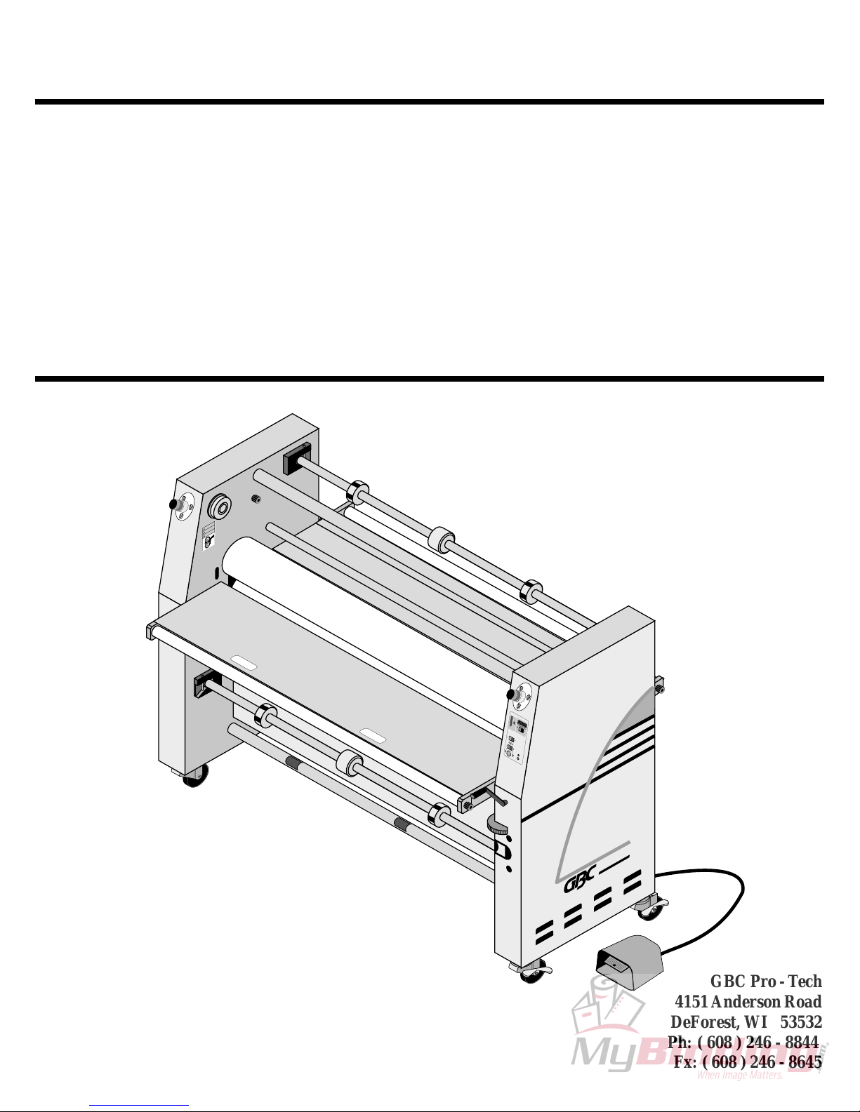
FALCON 60 H
OPERATION & MAINTENANCE
MANUAL
© APRIL 2001 GENERAL BINDING CORPORA TION. ALL RIGHTS RESERVED.
Do not duplicate without written permission.
ARNNG
W
HTUN
R
AC
A
N
S
M
F-60 H
PRO-TECH
GBC Pro - T ech
4151 Anderson Road
DeForest, WI 53532
Revision : A Ph: ( 608 ) 246 - 8844
Part number : 930 - 063
Fx: ( 608 ) 246 - 8645
Page 3
Read me fileF 60 H Operation and Maintenance Manual
Read Me File . . . . . . . . .
The information in this publication is provided for reference and is believed to be accurate and complete. General Binding Corporation is not liable for errors in this publication or for
incidental or consequential damage in connection with the furnishing or use of the information
in this publication, including, but not limited to, any implied warranty of fitness or merchantability for any particular use.
General Binding Corporation reserves the right to make changes to this publication and
to the products described in it without notice. All specifications and information concerning
products are subject to change without notice.
Reference in this publication to information or products protected by copyright or patent
does not convey any license under the rights of General Binding Corporation or others. General
Binding Corporation assumes no liability arising from infringements of patents or any other
rights of third parties.
This publication is copyrighted © 2001 by General Binding Corporation. All rights reserved. The information contained in this publication is proprietary and may not be reproduced, stored, transmitted, or transferred, in whole or in part, in any form without the prior and
express written permission of the Genral Binding Corporation.
The following information will explain how to move around within the electronic version
of this publication. The hand will change to a pointer finger identifying hyperlinked areas. When
moving from page to page, use
PAGE, use
from view to view, use
VIEW.
Should you find an error within this publication or would like to make a suggestion,
please utilize the fax correspondence sheet following this read me file and fax it to the number
provided. Your comments and help will ensure up to date information. Thank you.
to go back one PAGE and use to advance one PAGE. When moving
to return to a previous VIEW and use to advance to the next
to return to the first PAGE, use to advance to the last
© April 2001 General Binding Corporation
Page 4

Read me file F 60 H Operation and Maintenance Manual
This page intentionally left blank.
© April 2001 General Binding Corporation
Page 5

Fax Correspondence
Fax number : ( 608 ) 246 - 8645 Date :
To : Technical Coordinator at GBC Protech
4151 Anderson Road
DeForest, WI 53532
From :
Company :
Address :
Phone number : ( ) Fax number : ( )
Read me fileF 60 H Operation and Maintenance Manual
Re : F 60 H Operations and Maintenance Manual ( 930063A )
Section #: Page #:
Correction (s):
Additional comments:
© April 2001 General Binding Corporation
Page 6

Read me file F 60 H Operation and Maintenance Manual
This page intentionally left blank.
© April 2001 General Binding Corporation
Page 7

1.0 Safety
1.1 Symbols .......................................................................................................1 - 1
1.2 Safety precautions ......................................................................................1 - 2
1.3 Safety features ............................................................................................1 - 3
1.4 Installation ..................................................................................................1 - 4
T able of ContentsF 60 H Operation and Maintenance Manual
Table of Contents
1.5 Operations ..................................................................................................1 - 7
1.6 Applications ................................................................................................1 - 9
1.7 Troubleshooting .........................................................................................1 - 10
1.8 Maintenance ...............................................................................................1 - 10
1.9 Decal explanation .......................................................................................1 - 12
Figure 1.9.1 Safety label locations ............................................1 - 14
2.0 Warranty
2.1 Limited warranty information ....................................................................2 - 1
2.2 Exclusions to the warranty ........................................................................2 - 1
© April 2001 General Binding Corporation
Page I
Page 8

T able of Contents F 60 H Operation and Maintenance Manual
3.0 Specifications
3.1 General .......................................................................................................3 -1
3.2 Consumables ...............................................................................................3 - 2
3.3 Function ......................................................................................................3 - 3
3.4 Electrical ....................................................................................................3 - 4
3.5 Dimensions ................................................................................................3 - 5
Figure 3.5.1 Dimensions ...............................................................3 - 6
4.0 Installation
4.1 Pre-installation check list ...........................................................................4 - 1
Figure 4.1.1 Suggested floor layout .............................................4 - 3
4.2 Know your machine ...................................................................................4 - 4
4.3 Unpacking ..................................................................................................4 - 5
4.4 Shrink wrapped .........................................................................................4 - 5
4.5 Crated .........................................................................................................4 - 6
4.6 Accessory pack content ............................................................................4 - 8
Page II
© April 2001 General Binding Corporation
Page 9

4.7 Installing levelers .......................................................................................4 - 9
4.8 Leveling ......................................................................................................4 - 9
4.9 Connecting power ......................................................................................4 - 11
4.10 Safety check ............................................................................................4 - 13
5.0 Operations
5.1 Power ON/ OFF .........................................................................................5 - 2
T able of ContentsF 60 H Operation and Maintenance Manual
5.2 Control panel ..............................................................................................5 - 3
Figure 5.2.1 Front control panel ...................................................5 - 4
5.3 Set temperature ..........................................................................................5 - 5
5.4 Load/ unload film ........................................................................................5 - 6
5.5 Unwind brake tension .................................................................................5 - 9
5.6 Rewind brake tension .................................................................................5 - 9
5.7 Setting the nip ...........................................................................................5 - 10
5.8 Footswitch ..................................................................................................5 - 12
© April 2001 General Binding Corporation
Page III
Page 10

T able of Contents F 60 H Operation and Maintenance Manual
6.0 Applications
6.1 Helpful hints ...............................................................................................6 - 1
6.2 Temperature conversion chart ...................................................................6 - 3
6.3 Charts and diagrams ..................................................................................6 - 5
Blank chart .......................................................................................................6 - 6
Blank diagram ..................................................................................................6 - 7
Blank diagram w/ roll to roll option ................................................................6 - 9
Chart - Pre-coating substrates ........................................................................6 - 10
Diagram - Pre-coating substrates ...................................................................6 - 11
Chart - Mounting an image ............................................................................6 - 12
Diagram - Mounting an image .......................................................................6 - 13
Chart - PSA decaling ......................................................................................6 - 14
Diagram - PSA decaling .................................................................................6 - 15
Diagram - PSA decaling w/ roll to roll options ..............................................6 - 17
Chart - Lo-Melt decaling ................................................................................6 - 18
Page IV
© April 2001 General Binding Corporation
Page 11

T able of ContentsF 60 H Operation and Maintenance Manual
Diagram - Lo-Melt decaling ...........................................................................6 - 19
Diagram - Lo-Melt decaling w/ roll to roll options .........................................6 - 21
Chart - Mounting a decal ...............................................................................6 - 22
Diagram - Mounting a decal ..........................................................................6 - 23
Chart - PSA single sided lamination ( sled ) ...................................................6 - 24
Diagram - PSA single sided lamination ( sled ) ...............................................6 - 25
Chart - PSA single sided lamination ( craft paper ).........................................6 - 26
Diagram - PSA single sided lamination ( craft paper ) ...................................6 - 27
Diagram - PSA single sided lamination ( craft paper ) w/ roll to roll option ...6 - 29
Chart - PSA over-lamination of a mounted image .........................................6 - 30
Diagram - PSA over-lamination of a mounted image ....................................6 - 31
Chart - Lo-Melt over-lamination of a mounted image ...................................6 - 32
Diagram - Lo-Melt over-lamination of a mounted image ...............................6 - 33
© April 2001 General Binding Corporation
Page V
Page 12

T able of Contents F 60 H Operation and Maintenance Manual
7.0 Troubleshooting
7.1 Wave problems ..........................................................................................7 - 1
7.2 Film problems .............................................................................................7 - 3
7.3 Machine problems ......................................................................................7 - 4
7.4 Glossary .....................................................................................................7 - 5
8.0 Maintenance
8.1 Maintenance schedule ................................................................................8 - 1
8.2 Cleaning the rollers ...................................................................................8 - 2
8.3 Clean cabinets and covers ..........................................................................8 - 4
8.4 Clean the control panel ..............................................................................8 - 4
8.5 Chain tensioning .........................................................................................8 - 5
Page VI
© April 2001 General Binding Corporation
Page 13
F 60 H Operation and Maintenance Manual
Safety
1.0 Safety
CAUTIO N
Do n o t attempt to o p era te y ou r
Fa lco n 6 0 H lam in a tor u n til yo u
ha v e rea d th is s ectio n ca r efu lly !
Your safety, as well as the safety of others, is
important to GBC Films Group. This section contains
important safety information.
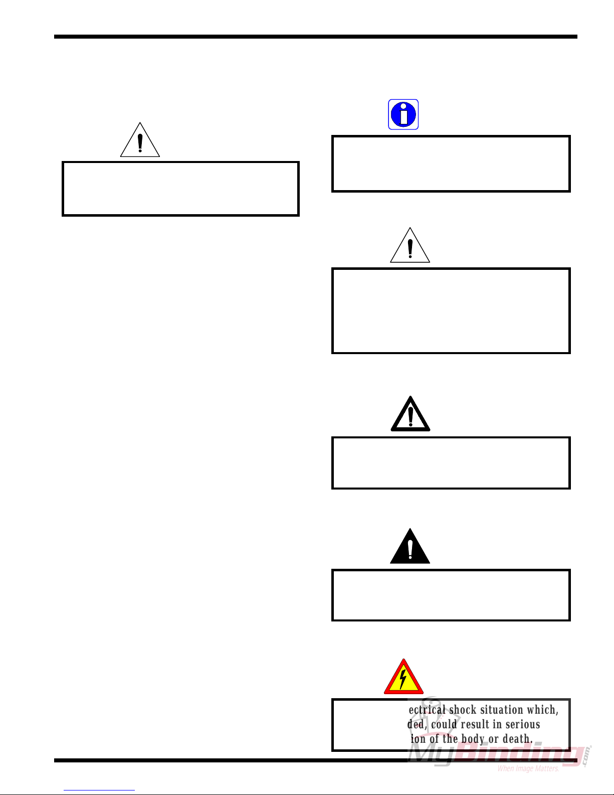
1.1 Symbols
INFORMATION
Indicates helpful information that should be
considered before, during, or after an
action, step or procedure is given.
CAUTION
Indicates a potentially hazardous situation
which, if not avoided, could result in minor
or moderate injury, or alerts against unsafe
practices or alerts against actions which
could damage the product.
The following symbols are used throughout this
manual to indicate Information, Caution, Warning,
Danger and Electrical Shock conditions.
WARNING
Indicates a potentially hazardous situation
which, if not avoided, could result in serious
injury.
DANGER
Indicates an imminently hazardous situation
which, if not avoided, could result in death
or serious injury.
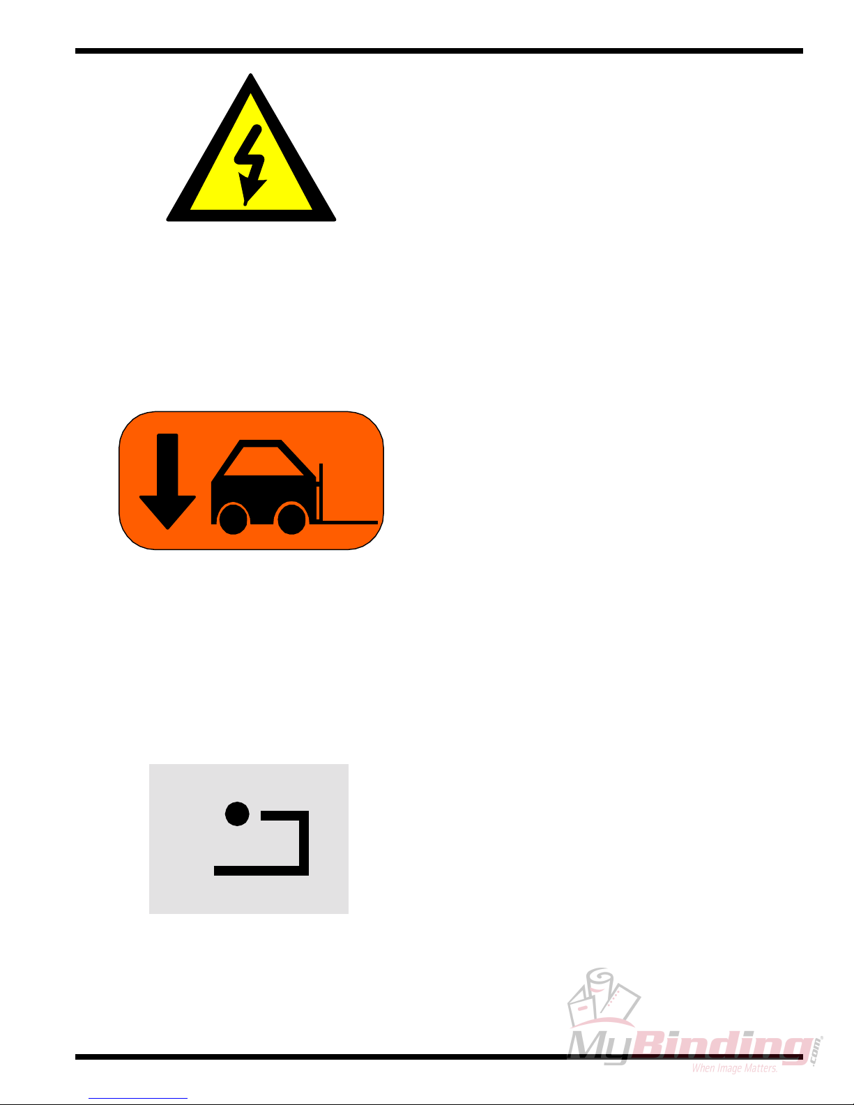
ELECTRICAL
SHOCK
© April 2001 General Binding Corporation
Indicates an electrical shock situation which,
if not avoided, could result in serious
paralyzation of the body or death.
Page 1 - 1
Page 14
Safety F 60 H Operation and Maintenance Manual
1.2 Safety precautions
DANGER
At these temperatures there is a danger of
severe burn if the rolls are touched during
The Falcon 60 H laminator has been designed
with safety as a primary consideration; however, you must
become thoroughly familiar with the controls, proper
operation, proper service procedures and safety features
of the laminator before using or servicing the unit.
The manual main roller lift mechanism used to
provide downward pressure on the upper main roller is
capable of producing forces greater than 400 pounds.
This force is applied to any object presented in the opening
( called the nip ) between the two rollers.
The word qualified is defined below;
Qualified;
setup, operation or servicing.
Use care in lowering the upper laminating roller
and know how to react quickly in an emergency. The
main laminator roll up / down control is located on the
right side of the machine within the front. Before turning
the crank handle to set the GAP down, ensure that nothing
is in the nip area.
WARNING
Keep h an d s an d fingers clear of the
laminator roller nip when adjusting nip.
You can be CRUSHED or BURNED!
• Any engineer that has experience with electrical
and mechanical design of lamination equipment. The
engineers should be fully aware of all aspects of safety
with regards to lamination equipment.
• Any commissioning or service engineer must be
of competent nature, trained and qualified to GBC Films
Group standards to fulfill that job. This person will have
completed and passed the full service training course from
GBC Pro-T ech.
• Any GBC T echnician, GBC Specialist, and / or
GBC Films Group T echnician that has been through the
GBC Pro-T ech service training course.
In addition, the main laminating rollers of the
Falcon 60 H can reach temperatures up to 200oF (100oC).
Page 1 - 2
© April 2001 General Binding Corporation
Page 15

F 60 H Operation and Maintenance Manual
1
/
4
t
u
r
n
POWER
Reset
ROT CH
F 60 H
PHOTO-EYE
Safety
1.3 Safety features
The laminator is equipped with four emergency
stops ( E-STOP ). Two are located at the front of the
cabinets and two are at the rear of the cabinets.
E-STOP
E-STOP
T o continue operation, all E-STOPs must be in
the unlatched position. T o reset, twist the E-STOP 1/4
turn counter clockwise.
Press RESET located on the control side cabinet
at the rear of the machine just above the main power on/
off.
T o engage an E-STOP, press down on any of the
four . Any E-STOP, when engaged, removes power to
the laminator .
INFORMATION
The machine will only operate if all four
E-STOPS are in the unlatched position.
© April 2001 General Binding Corporation
The nip area is protected by a electric photo-eye
which shoots a beam in front of the nip across the width
of the rollers. When this beam is broken, power to the
drive motor is removed. The objetc must be removed to
clear the photo-eye. The motor engage switch must be
pressed again to continue motor operation.
Page 1 - 3
Page 16
Safety F 60 H Operation and Maintenance Manual
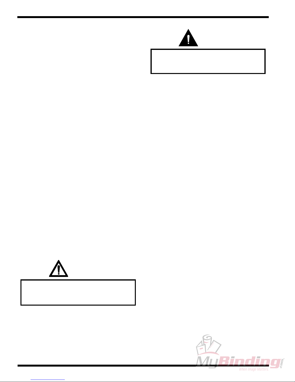
1.4 Installation
WARNING
The Fa lcon 60 H L am inator is a large and
The following symbols are positioned at various
points in Section 4 Installation.
CAUTION
Failure to follow the pre-installation check
list can result in damage to the laminator.
heavy piece of equipment. It is necessary to
employ LICENSED RIGGERS ONLY to
move the lam inator. The lam inator is not
de sig n e d to b e tip p e d u p or sidew a y s in a n y
way. Such action disturbs the exact
alignment of the rolling parts of the machine
and requ ires extensive realignm en t. You can
be crushed or seriously injured.
INFORMATION
ALL SHIPMENTS ARE EX-WORKS.
dock, title passes to the buyer. Please review
WARNING
The operating environment must be free of
dust, flammable liquids and vapors. You can
be injured by inhaling chemical vapors.
WARNING
Vapor build up or stored flammable
liquids can cause a fire. Excessive
dust can damage the laminator.
At our
your insurance coverage prior to shipment,
as you are responsible for all subsequent
freight charges and risks.
INFORMATION
Before signing the Bill of Lading, you
should be sure to inspect the crate
and / or pallet for signs of damage or
missing items; if applicable, make
note of this on the Bill of Lading.
CAUTIO N
Do n ot locate the Falcon 60 H w h ere air is
blowing directly on the machine. Th e air
flow can co ol the rolls un ev en ly an d resu lt
in poor output quality.
Page 1 - 4
WARNING
The unpacking process requires at least two
people. You can be severely injured, crushed
or cause damage to the laminator.
© April 2001 General Binding Corporation
Page 17
F 60 H Operation and Maintenance Manual
INFORMATION
Depending on the destination and customer
preference, your machine may be shipped in
various ways. The laminator may arrive
shrink wrapped or in a plywood crate on a
skid. Please follow the unpacking procedure
that pertains to your method of shipment.
Safety
CAUTION
Do not allow the top to fall into the crate. It
can damage the laminator.
INFORMATION
CAUTION
Do not use a knife or other sharp object to
remove the shrink wrap from around the
laminator. You can cause irreparable
damage to the rollers.
WARNING
Do not attempt to move the laminator across
anything other than a flat level surface
without trained and qualified riggers. You
can be crushed or seriously injured.
Do not put packing screws on the floor.
They can cause problems when trying to roll
the laminator into position or you can
become injured if stepped on.
CAUTION
A second person must support the side
labeled 5 in Figure 4.5.1 It can fall and
damage the laminator or cause harm to you
and others.
INFORMATION
GBC Film Group's warranty does not
cover malfunction of the equipment due to
mishandling and / or tipping. GBC Films
Group bears no responsibility for personal
injury or damage due to moving the
laminator improperly.
© April 2001 General Binding Corporation
WARNING
Do not attempt to use the ramps if they are
not secured to the pallet. Ensure the pallet is
on a flat even surface before attempting to
roll the machine off.
Page 1 - 5
Page 18
Safety F 60 H Operation and Maintenance Manual
IN F O RM A T ION
Ab out recycling: The crate compon ents can
be reused for shipping the laminator again
or can be disassembled and the wood and
screws recycled. Th e sh rink wrap is not
recyclable, so it must be d iscarded.
CAUTION
Do n o t m ove th e leveling nu t when securin g
the inside nut to the cabinet.
WARNING
Follow the correct wiring diagram when
supplying power to the laminator. If
improperly connected, you can be seriously
injured or cause damage to the laminator.
WARNING
Do not wear ties, loose fit clothing or
dangling jewelry while operating or
servicing the laminator. These items can get
caught in the nip and choke you or you can
be crushed or burned.
IN F OR MAT ION
Yo u will ne ed the con tr o l sid e ca b in e t co v e r
off to conn ect the electrical power.
ELECTRICAL
SHOCK
Only a qualified electrician should connect
power to the laminator. You can be severely
shocked, electrocuted or cause a fire if
power is improperly applied.
WARNING
If a safety feature is not working
properly, contact your local service
representative immediately.
CAUTIO N
Do not use a hard substrate or a substrate
with sharp edges. You may cause damage to
the lam inating rollers!
Page 1 - 6
© April 2001 General Binding Corporation
Page 19
F 60 H Operation and Maintenance Manual
1.5 Operations
The following symbols are positioned at various
points in Section 5 Operations.
WARNING
Do not w ear ties, loose fit clothing or
dangling jewelry while operating or
servicing the lam in ator. Th ese item s can g et
caught in the nip and choke you or you can
be crushed or burned.
Safety
WARNING
W h en the lam in ator ro llers are in
motion, keep hands and fingers
away from the nip of the rollers.
You may be CRUSHED or BURNED!
WARNING
When o p e ra tin g th e la minato r u sing the
footsw itch, keep h an d s an d fin gers
away from the nip of the rollers.
You may be CRUSHED or BURNED!
IN F OR MAT ION
The m ac h in e will only o p e ra te if a ll
four emergency stop s are u n latched an d
RESET has been pressed.
WARNING
It is u n sa fe to sh e et f eed with o u t the
pressu re plate pro p erly placed o n
the fron t feed tab le.
WARNING
Do n o t opera te the lam ina tor, except
during web set up, without the front
and rear feed tables in position.
CAUTIO N
En su re the roll of lam in ate is loaded
properly on the unwind shaft.
Exposed adhesive should be facing
away from the rollers.
Th is will pre v ent hou r s o f ro ll cle a n in g !
WARNING
Keep h an d s and fin gers clear of th e
lamina tor roller nip when ch an gin g G A P .
You can be CRUSHED or BURNED!
© April 2001 General Binding Corporation
IN F OR MAT ION
Th e P o ly -in / P o ly-o u t diagra ms refe r to th e
upper rolls of film only. The mount adhesive
and craft p ap ers are fo r referen ce on ly.
Page 1 - 7
Page 20
Safety F 60 H Operation and Maintenance Manual
WARNING
Never leave the unw ind shaft out of the
unwind support saddle unless loading
or unloading film.
CAUTIO N
W h en u sing tw o rolls on th e m ach ine,
ensur e the film w idth s are id entical.
Exposed adhesive can cause complications.
CAUTIO N
CAUTIO N
Excess pressure can damage the laminating
rollers. Alway s u se the m in imu m roll
pressure n ecessa ry to co m p lete the task.
CAUTIO N
Objects other than m edia, film or approved
substrates, will cause irreparable damage
to the rollers if caugh t in the n ip.
CAUTIO N
Never use an open blade near the laminating
rollers. You may cut the rollers or yo ur self.
IN F OR MAT ION
Always use the minimum amount
of bra ke fo r the job .
IN F OR MAT ION
If mo re bra ke is need ed, ad d an O-ring
to the brake side of the rewind.
Sharp edges on a substrate
should be filed smooth.
Sha rp edg es can C U T th e rollers!
IN F OR MAT ION
Ex c es siv e pressu r e will cause the
substrate to bow or flatten.
IN F OR MAT ION
De n s ity o f the substrate w ill determine th e
amoun t of pressure you may use.
Page 1 - 8
© April 2001 General Binding Corporation
Page 21

F 60 H Operation and Maintenance Manual
1.6 Applications
The following symbols are positioned at various
points in Section 6 Applications.
Safety
IN F OR MAT ION
Ex c es siv e pressu r e will cause the
substrate to bow or flatten.
WARNING
Do not wear ties, loose fit clothing or
dangling jewelry while operating or
servicing the laminator. These items can get
caught in the nip and choke you or you can
be crushed or burned.
IN F OR MAT ION
Use film brake tension to control the
separa tion po int of the r elease liner.
IN F OR MAT ION
Excessive brake tension may cause the
imag e to curl. A lw ays u se the minimum
amoun t of brake for the job.
CAUTIO N
Excess pressure can damage the laminating
rollers. Alway s u se the m in imu m roll
pressure n ecessa ry to co m p lete the task.
IN F OR MAT ION
Sp ee d s and tempera tu r es will affe ct th e
bond strength of Lo-Melt adhesives.
IN F OR MAT ION
Th e m o un t ad h esive m u st no t exceed 1 in.
the w idth of the substrate. If it does, you
w ill e xp e rie n ce c omplications with th is
application.
© April 2001 General Binding Corporation
IN F OR MAT ION
Never stop the lam inator when an im age is
within the n ip of th e rollers.
IN F OR MAT ION
Lam inates and papers should always be
stored in a co n trolled env irom en t.
Page 1 - 9
Page 22
Safety F 60 H Operation and Maintenance Manual
1.7 Troubleshooting
The following symbols are positioned at various
points in Section 7 T roubleshooting.
WARNING
Do not wear ties, loose fitting clothing or
dangling jewelry while operating or
servicing the laminator. These items can get
caught in the nip and choke you or you can
be crushed or burned.
1.8 Maintenance
The following symbols are positioned at various
points in Section 8 Maintenance.
WARNING
Do not wear ties, loose fit clothing or
dangling jewelry while operating or
servicing the laminator. These items can get
caught in the nip and choke you or you can
be crushed or burned.
INFORMATION
For optimal temperature settings of
various laminates, contact your
supplier or sales representative.
INFORMATION
Improper maintenance, can
result in poor output quality.
ELECTRICAL
SHOCK
Remove power from the laminator before
servicing. You can be severely shocked,
electrocuted or cause a fire.
IN F O RM A T ION
Page 1 - 10
Below is a recommended maintenance
schedule. Before performing any of the steps
listed, read through the procedures first.
Please follow the instructions pertaining to
the step you are perform ing.
© April 2001 General Binding Corporation
Page 23
F 60 H Operation and Maintenance Manual
CAUTION
Safety
ELECTRICAL
SHOCK
Excessive pressure can destroy the silicone
layer by pressing to hard or scrubbing
too long in one spot.
CAUTION
Exercise care when cleaning the laminating
rollers with 80% isopropyl alcohol:
Use only in a well ventilated area
Wear rubber gloves
Use only on cool rolls
CLEANING HEATED ROLLERS CAN
IGNITE THE FUMES!
Remove power from the laminator before
cleaning. You can be severely shocked,
electrocuted or cause a fire.
ELECTRICAL
SHOCK
Do not use liquid or aerosol cleaners on the
laminator. Do not spill liquid of any kind on
the laminator. You can be severely shocked,
electrocuted or cause a fire. Use only a damp
cloth for cleaning unless other wise
specified.
WARNING
CAUTION
Do NOT pick or pull heat activated adhesive
off the rolls when they are cold. You can
cause irreparable damage to the
laminating rolls.
Always practice lock out/ tag out procedures
WARNING
W h en op erating the laminator using the
footswitch, keep hands and fingers
away from the nip of the rollers.
You may be CRUSHED or BURNED!
Rem o ve ALL p ow er to th e lam in ator b efo re
remo ving an y ca bin et covers.
You may be shocked or electrocuted!
WARNING
wh en p erforming any ty pe o f service or
main tena nce work on the machine.
IN F OR MAT ION
Th e m o tor con trols the tension of th e bo th
cha ins. If on e c h ain is still too lo o se ,
a half link may be removed.
© April 2001 General Binding Corporation
Page 1 - 11
Page 24
Safety F 60 H Operation and Maintenance Manual
y
g
g
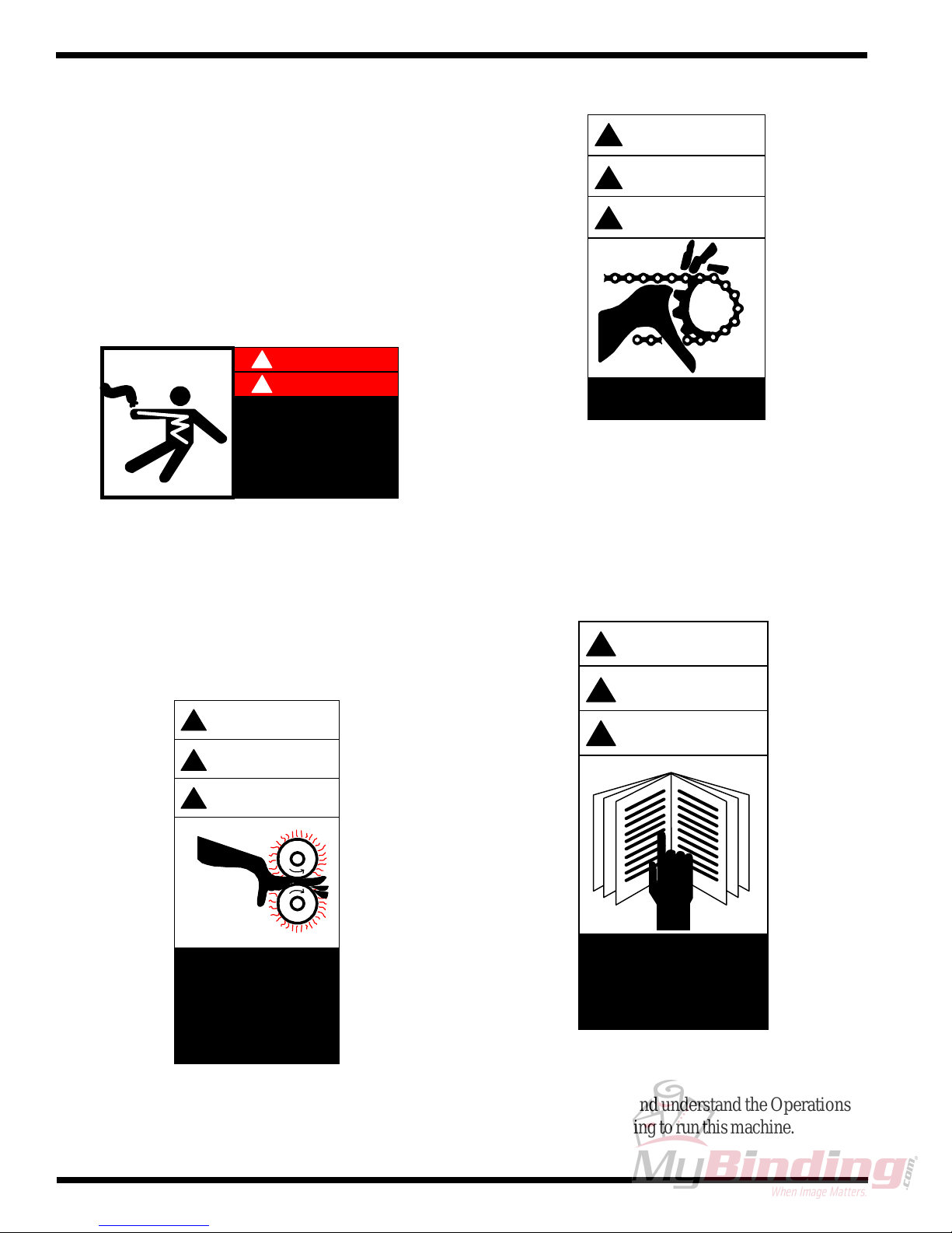
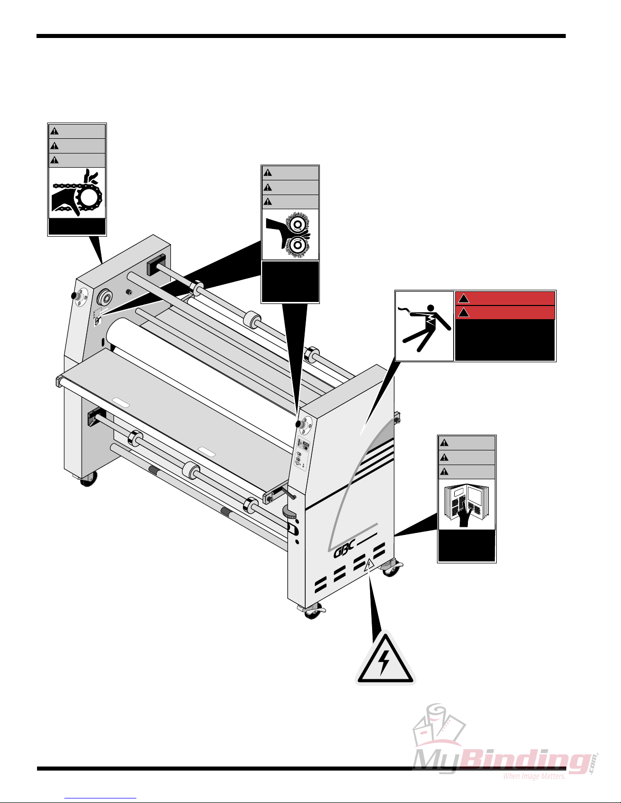
1.9 Label locations
WARNING
!
ACHT UNG
Posted at various locations on the Falcon 60 H
Laminator are important safety labels. Pay careful
attention to these labels at all times! Figure 1.12.1
illustrates the location of each of these labels.
!
DANGER
!
GEFAHR
HAZARDOUS
VOLTAGE
To be serviced only
by trained and
authorized personnel.
Lockout power b efore
servicing
Moving Parts: Keep hands and fingers away . Y ou
may be crushed and/ or cut.
!
M ISE EN GARDE
!
Moving parts can
crush and cut.
Hazardous V oltage: Do not open these cabinets. This
machine is to be serviced only by trained and authorized
personnel.
WARNING
!
ACHTUNG
!
MISE EN GARDE
!
Crush and burn
hazard. Sta
of movin
Stop m achine and
raise roll before
cleanin
clear
rollers.
.
WARNING
!
ACHTUNG
!
M ISE EN G ARDE
!
Carefully read Operator's
Manual before handling
this machine. Observe
instructions and safety
rules when operating.
Roller Pinch Point: Keep hands and fingers away.
Y ou may be crushed and/ or burned.
Page 1 - 12
Read Manual: Read and understand the Operations
Manual before attempting to run this machine.
© April 2001 General Binding Corporation
Page 25
F 60 H Operation and Maintenance Manual
Electrical Shock: Live voltage present. Exercise
extreme caution. Y ou may be electrocuted!
Safety
Refer to Figure 1.9.1 Label Placement illustrates
the location of each of these labels.
Lift Here: This point may be used as a lifting point. If
ignored, damage will occur to the laminator.
Reset: Machine reset. Press after initiating power to the
laminator or after an E-STOP or E-CABLE has been
engaged then reset.
© April 2001 General Binding Corporation
Page 1 - 13
Page 26
Safety F 60 H Operation and Maintenance Manual
Figure 1.9.1 Safety label locations
(Inside cabinet)
WARNING
ACHTUNG
MISE EN GARDE
WARNING
ACHTUNG
MISE EN GARDE
Moving parts can
cruch and cut.
Crush and burn
hazard. Stay clear
of moving rollers.
Stop machine and
raise roll before
cleaning.
ARNN
A HU
N
S
M
(Inside cabinet)
!
DANGER
!
GEFAHR
HAZARDOUS
VOLTAGE
To be serviced only
by trained and
authorized personnel.
Lockout power before
servicing
F-60 H
PRO-TECH
WARNING
ACHTUNG
MISE EN GARDE
Carefully read operator's
Manual before handling
this machine. Observe
instructions and safety
rules when operating.
Page 1 - 14
© April 2001 General Binding Corporation
Page 27

WarrantyF 60 H Operation and Maintenance Manual
2.0 Warranty
GBC Films Group warrants the equipment sold
is free from defects in material and workmanship for a
period of one ( 1 ) year parts ( excludes normal wear
items ) and 90 days labor from the date of installation.
This warranty is the only warranty made by GBC Films
Group and cannot be modified or amended.
GBC Films Group’s sole and exclusive
liability and the customer’s sole and exclusive
remedy under this warranty shall be, at GBC Films
Group’s option, to repair or replace any such
defective part or product. These remedies are only
available if GBC Films Group’s examination of the
product discloses to GBC Films Group’ s satisfaction
that such defects actually exist and were not caused
by misuse, neglect, attempt to repair , unauthorized
alteration or modification, incorrect line voltage, fire,
accident, flood, or other hazard.
THE WARRANTY MADE HEREIN IS IN
LIEU OF ALL OTHER WARRANTIES,
EXPRESS OR IMPLIED, INCLUDING
ANY WARRANTY OR
MERCHANTABILITY OR FITNESS
FOR A PARTICULAR PURPOSE. GBC
FILMS GROUP WILL NOT BE LIABLE
FOR PROPERTY DAMAGE OR
PERSONAL INJURY ( UNLESS
PRIMARILY CAUSED BY ITS
NEGLIGENCE ), LOSS OF PROFIT OR
OTHER INCIDENTAL OR
CONSEQUENTIAL DAMAGES
ARISING OUT OF THE USE OR
INABILITY TO USE THE EQUIPMENT.
2.2 Exclusions to the
2.1 Limited Warranty
This warranty specifically does not cover damage
to the laminating rollers caused by knives, razor blades,
other sharp objects, failure caused by adhesives or
improper use of the machine. Warranty repair or
replacement does not extend the warranty beyond the
initial one year period from the date of delivery .
CAUTION
Warranty
This warranty specifically does not
cover;
1. Damage to the laminating rollers caused by knives,
razor blades, other sharp objects or failure caused
by adhesives.
2. Damage to the machine caused by lifting, tilting and /
or any attempt to position the machine other than
rolling on the installed castors on even surfaces.
3. Improper use of the machine.
Unauthorized customer alterations will
void this warranty.
© April 2001 General Binding Corporation
4. Damage due from unqualified person(s) servicing the
machine.
Page 2 - 1
Page 28

Warranty F 60 H Operation and Maintenance Manual
Qualified
• Any engineer that has experience with electrical
and mechanical design of lamination equipment. The
engineers should be fully aware of all aspects of safety
with regards to lamination equipment.
• Any commissioning or service engineer must be
of competent nature, trained and qualified to GBC Films
Group standards to fulfill that job. This person will have
completed and passed the full service training course from
GBC Pro-T ech.
• Any GBC T echnician, GBC Specialist, and / or
GBC Films Group T echnician that has been through the
GBC Pro-T ech service training course.
Page 2 - 2
© April 2001 General Binding Corporation
Page 29

3.0 Specifications
Specifications provide all of the technical data for
the Falcon 60 H Laminator.
3.1 General
SpecificationsF 60 H Operation and Maintenance Manual
Description:
Features:
• Cost efficient, wide format color finisher for the sheet
fed ink jet market. The Falcon 60 H is a self standing,
bi-directional cold mounter and laminator with the abilty
to run Lo-Melt overlaminate.
• T wo unwinds ( 1 upper, 1 center/ front )
• One rewind ( upper front )
• Infeed and oufeed tables
• Footswitch
• Front and rear table idlers
• Bi-directional system
• Four E-STOPs
• Photo-eye nip protection
• Roll to roll capability ( option)
Applications:
© April 2001 General Binding Corporation
• Single sided lamination
• Mounting
• Decaling
• Low melt film
Page 3 - 1
Page 30

Specifications F 60 H Operation and Maintenance Manual
3.2 Consumable
Film types:
Film diameters:
Core size:
• Pressure sensitive laminates
• Pressure sensitive adhesives
• Low melt laminates
• Up to a 8 in. roll diameter ( 20.3 cm )
• 3 in. core standard ( 7.62 cm )
• 2-1/4 in. optional ( must have optional core adapters )
( 5.72 cm )
Film widths:
Paper widths:
Mounting thickness:
Safety:
• 62 in. Pressure sensitive ( 162.6 cm )
• 60 in. Low Melt ( 157.8 cm )
• 62 in. maximum paper width ( 157.8 cm )
• Up to 1 in. thick ( 2.54 cm ) either direction
• Designed to UL safety standards
Page 3 - 2
© April 2001 General Binding Corporation
Page 31

3.3 Function
SpecificationsF 60 H Operation and Maintenance Manual
Speed:
Motor:
Heating capabilities:
Controls:
• 0 - 16 ft / min ( 0 - 4.6 m / min )
• 2-1/4 horse power drive motor
• Bi-directional D.C. motor
o
• 68
F - 200oF ( 20oC - 93oC )
• Front control panel
• Footswitch
Roll design:
© April 2001 General Binding Corporation
• High release silicone rollers
Page 3 - 3
Page 32

Specifications F 60 H Operation and Maintenance Manual
3.4 Electrical
United Statesand Canada:
B.T .U. output:
Heater wattages:
Amperage draw:
• 230 ~ 240 VAC, 50/60 Hz, single phase, 40 amps
• 18,520 B.T.U. / hour
• 5429 watts per heater @ 240 vac
• No heat, motor only : 1 - 3 amps
• T op heat and motor : 25 - 30 amps
D/C voltage used:
A/C voltage used:
Page 3 - 4
• 24 vdc
• 230~ 240 vac ( minimum )
© April 2001 General Binding Corporation
Page 33

3.5 Dimensions
W eight:
SpecificationsF 60 H Operation and Maintenance Manual
Uncrated:
Crated:
Dimensions
Uncrated:
Crated
• 1350 lbs. ( 612 kg. )
• 1625 lbs. ( 737 kg. )
• 80 in. (L) x 38.5 in. (W) x 57 in. (H)
( 203 cm (H) x 98 cm (W) x 145 cm (L) )
Refer to Figure 3.5.1 Dimensions
• 90 in. (L) x 44 in. (W) x 68 in. (H)
( 229 cm (H) x 112 cm (W) x 173 cm (L) )
Nip Height:
© April 2001 General Binding Corporation
• 38 in. ( 96.5 cm )
Page 3 - 5
Page 34

Specifications F 60 H Operation and Maintenance Manual
Figure 3.5.1 Dimensions
80 in.
( 203 cm )
ARNING
W
HTUNG
AC
MS N AR
57 in.
( 145 cm )
F-60 H
PRO-TECH
38.5 in.
( 98 cm )
Page 3 - 6
© April 2001 General Binding Corporation
Page 35

InstallationF 60 H Operation and Maintenance Manual
4.0 Installation
GBC Films Group is committed to a program of
ongoing product improvement. As a result, we are
providing these instructions so you can insure that your
new Falcon 60 H Laminator is properly and securely
unpacked, moved, and installed. Installation should be
performed by a qualified technician.
Before a Falcon 60 H Laminator can be installed,
there are a few requirements that must be met. Make
certain that each of the requirements listed in the following
pre-installation checklist are met before beginning
installation.
CAUTION
Is the environment appropriate for the laminator?
The laminator requires a clean, dust and vapor
free environment to operate properly. Do not
locate it where there is air blowing directly on the
machine.
Have you contacted a certified electrician to both
wire the laminator and ensure that adequate power
is being supplied, having the appropriate capacity ,
over current protection and safety lockouts are
available?
WARNING
The operating environment must be free of
dust, flammable liquids and vapors. You can
be injured by inhaling chemical vapors.
Failure to follow the pre-installation check
list can result in damage to the laminator.
4.1 Pre-installation
Are doorways and hallways wide enough for the
laminator to be moved to the installation site?
Is there ample room for the laminator?
A work area must be established that allows for
operation in both the front and rear of the
laminator and provides space for efficient material
flow. Figur e 4.1.1 illustrates a typical machine
area layout.
WARNING
Vapor build up or stored flammable
liquids can cause a fire. Excessive
dust can damage the laminator.
CAUTIO N
Do n ot locate the Falcon 60 H w h ere air is
blowing directly on the machine. Th e air
flow can co ol the rolls un ev en ly an d resu lt
in poor output quality.
© April 2001 General Binding Corporation
Page 4 - 1
Page 36

Installation F 60 H Operation and Maintenance Manual
The Falcon 60 H requires single phase, 230 to
240 vac, 50/ 60 Hz, 40 amp service. No other
type of connection is permitted.
WARNING
The Fa lcon 60 H L am inator is a large and
heavy piece of equipment. It is necessary to
employ LICENSED RIGGERS ONLY to
move the lam inator. The lam inator is not
de sig n e d to b e tip p e d u p or sidew a y s in a n y
way. Such action disturbs the exact
alignment of the rolling parts of the machine
and requ ires extensive realignm en t. You can
be crushed or seriously injured.
For instructions on how to connect power,
proceed to 4.9 Connecting power in this section.
Page 4 - 2
© April 2001 General Binding Corporation
Page 37

Figure 4.1.1 Suggested Floor Layout
4 ft. x 6 ft. (1.22 m x 2 m )
Work table on wheels
InstallationF 60 H Operation and Maintenance Manual
20 ft.
( 6 m )
8.2 ft.
( 2.57 m )
38.5"
( .98 m )
Table height
37-3/4 in. (.95 - .96 m)
78 in.
( 2 m )
Electrical
supply
3 ft. ( 1 m )
Front operating position
8.2 ft.
( 2.57m )
© April 2001 General Binding Corporation
4 ft. x 6 ft. (1.22 m x 2 m )
Work table on wheels
Table height
37-3/4 in. (.95 - .96 m)
13' ( 4 m)
Page 4 - 3
Page 38

Installation F 60 H Operation and Maintenance Manual
4.2 Know your machine
Before performing any procedure within this
manual, it is recommended that you take time to know
the parts of your new machine.
Figure 4.2.1 The laminator
Drive side
( Left )
Rear
Figure 4.2.3 Idlers and unwinds
Upper unwind
Web idler
Rear table idler
Tie bars
F-60 H
Lower Unwind
PRO TECH
Front table idler
Figure 4.2.4 Misc.
Front
F-60 H
Control side
PRO TECH
( Right )
Figure 4.2.2 Safety and controls
Rewind drive
Main roller lift
Core grip
E-stop
Upper unwind brake
Photo-eye
Unwind saddle
Front table
Figure 4.2.5 Power
Run/ Stop
Main rollers
Rear table
F-60 H
PR -TECH
Castors
Core support
F-60 H
Foot switch
Lower unwind brake
Control panel
Page 4 - 4
POWER
H
C
-TE
O
R
P
On/ Off
© April 2001 General Binding Corporation
Reset
Page 39

InstallationF 60 H Operation and Maintenance Manual
4.3 Unpacking
INFORMATION
ALL SHIPMENTS ARE EX-WORKS.
dock, title passes to the buyer. Please review
your insurance coverage prior to shipment,
as you are responsible for all subsequent
freight charges and risks.
INFORMATION
Before signing the Bill of Lading, you
should be sure to inspect the crate
and / or pallet for signs of damage or
missing items; if applicable, make
note of this on the Bill of Lading.
At our
With regards to your shipping methods, use one
of the following procedure described to safely and
properly unwrap / uncrate your laminator .
4.4 Shrink Wrapped
a) Inspect the machine for any obvious shipping
damages upon receipt. Report any damage to
your carrier .
b) Carefully unwrap the shrink wrap from around
the laminator .
INFORMATION
Depending on the destination and customer
preference, your machine may be shipped in
various ways. The laminator may arrive
shrink wrapped or in a plywood crate on a
skid. Please follow the unpacking procedure
that pertains to your method of shipment.
WARNING
The unpacking process requires at least two
people. You can be severely injured, crushed
or cause damage to the laminator.
Do not attempt to move the laminator across
without trained and qualified riggers. You
CAUTION
Do not use a knife or other sharp object to
remove the shrink wrap from around the
laminator. You can cause irreparable
damage to the rollers.
c) Carefully wheel your Falcon 60 H Laminator
with a second person to the installation site.
WARNING
anything other than a flat level surface
can be crushed or seriously injured.
© April 2001 General Binding Corporation
Page 4 - 5
Page 40

Installation F 60 H Operation and Maintenance Manual
4.5 Crated
WARNING
The Fa lcon 60 H L am inator is a large and
heavy piece of equipment. It is necessary to
employ LICENSED RIGGERS ONLY to
move the lam inator. The lam inator is not
de sig n e d to b e tip p e d u p or sidew a y s in a n y
way. Such action disturbs the exact
alignment of the rolling parts of the machine
and requ ires extensive realignm en t. You can
be crushed or seriously injured.
To uncrate the laminator
a) Remove the top of the crate and then the sides
in the order shown in Figure 4.5.1
CAUTION
Do not allow the top to fall into the crate. It
can damage the laminator.
INFORMATION
GBC Film Group's warranty does not
cover malfunction of the equipment due to
mishandling and / or tipping. GBC Films
Group bears no responsibility for personal
injury or damage due to moving the
laminator improperly.
Tools required
• # 2 Phillips head screwdriver
• 7/8” open end wrench or adjustable wrench
• Crow bar
• A second person
INFORMATION
Do not put packing screws on the floor.
They can cause problems when trying to roll
the laminator into position or you can
become injured if stepped on.
CAUTION
A second person must support the side
labeled 5 in Figure 4.5.1 It can fall and
damage the laminator or cause harm to you
and others.
Page 4 - 6
© April 2001 General Binding Corporation
Page 41

InstallationF 60 H Operation and Maintenance Manual
Figure 4.5.1 Disassembling of the crate
3
A
U
A
1
5
4
F-60 H
R E
2
Removing the shrink wrap
Moving the laminator
a) Have the laminator rolled off the skid and placed
on the floor by licensed riggers. The ramps
included with the laminator can be secured utilizing
screws removed from the disassembled crate.
Figure 4.5.2 illustrates positioning of the ramps.
WARNING
Do not attempt to use the ramps if they are
not secured to the pallet. Ensure the pallet is
on a flat even surface before attempting to
roll the machine off.
a) Gently unwrap the shrink wrap from around the
laminator.
Figure 4.5.2 Positioning of the ramps
CAUTION
Do not use a knife or other sharp object to
remove the shrink wrap from around the
laminator. You can cause irreparable
damage to the rollers.
b) Move all packing materials to a safe distance.
b) Remove any plastic strapping and/or packing
paper taped to the rollers.
© April 2001 General Binding Corporation
Page 4 - 7
Page 42

Installation F 60 H Operation and Maintenance Manual
4.6 Accessory pack
CAUTION
Do not use a knife or other sharp object to
remove the shrink wrap from around the
laminator. You can cause irreparable
damage to the rollers.
unpacked and moved into final position, open the accessory
pack and verify the contents.
Once the Falcon 60 H Laminator has been
c) Remove all packing materials to a safe distance
from the laminator and dispose of properly .
d) Use two people to carefully roll the laminator to
the desired location.
INFORMATION
About recycling: The crate components can
be reused for shipping the laminator again
or can be disassembled and the wood and
screws recycled. The shrink wrap is not
recyclable, so it must be discarded.
contact your local service technician or sales
representative.
Accessory Pack contents
• One Fuse, 250 V, 20 amp ( 186 - 135 )
• T wo Fuses, 2,5 amp ( 186 - 220 )
• One fuse, 0.5 amp ( 186-016 )
• One Operators Manual ( 930 - 063 )
• One T owel ( 475 - 950 )
• One Zippy knife ( 475 - 620 )
• One strain relief for main power ( 175-201 )
• One rubber cement pad ( 930320 )
• One crank handle ( 629-018 )
• One O-ring ( 480 - 005 )
• Four leveling pads ( 470 - 101 )
• One T-handle, 1/4 in. ( 475 - 210 )
• One roll of masking tape ( 475 - 000 )
• One crank handle ( ??? - ??? )
• One BHCS ( floor stock item )
If you are missing any of the items listed above,
Page 4 - 8
Contacts:
GBC Parts ( 800 ) 790 - 7787
GBC Europe parts 33 - 45 - 535 - 7676
© April 2001 General Binding Corporation
Page 43

InstallationF 60 H Operation and Maintenance Manual
4.7 Installing levelers
Leveling of the machine is a customer option. If
you choose not to level the laminator and you encounter
output problems, please level the machine and try your
application again before calling for technical support.
Tools required
• ( 2 ) 3/4” open end wrenches
• Four leveling pads
( from the accessory pack )
4.8 Leveling
Leveling of the laminator is very important in the
way the machine performs. Leveling is crucial to the tram
( tracking ) of the materials through the machine.
Tools required
• ( 2 ) 3/4 in. open end wrenches
• 1/8 in. allen wrench
• Level
• A second person
a) V erify that the laminator has sufficient room
around it to load film, walk around and to be
serviced if necessary .
b) Place one leveling pad on each of the four
leveling bolts on the laminator.
Jam n uts
Leveling pads
a) W ith a 1/8 in. allen wrench, remove the drive
side and control side cabinet covers by;
1) Loosen the three screws along the
bottom.
2) Remove the seven screws along the
top and sides of the cover.
2
F-60 H
c) Use a 3/4 in. open end wrench to secure the
jam nut against the leveling pad.
© April 2001 General Binding Corporation
PRO-TECH
1
Page 4 - 9
Page 44

Installation F 60 H Operation and Maintenance Manual
b) Loosen the nut on the inside of both cabinets
securing the leveling bolt with a 3/4 in. wrench.
Inside nuts
c) Position the level on the top of the control side
cabinet.
e) Position the level on the top of the drive side
cabinet.
A
F-60 H
PRO-TECH
f) Level the drive side from front to back by
turning the leveling nut clockwise to raise or
counter clockwise to lower .
F-60 H
PRO TECH
d) Level the control side from front to back by
turning the leveling nut clockwise to raise or
counter clockwise to lower.
9
Leveling nuts
g) Position the level center of the upper tie bar.
F-60 H
PRO TECH
h) Level the laminator from drive side to control
side by turning the leveling nut clockwise to
raise or counter clockwise to lower.
Page 4 - 10
© April 2001 General Binding Corporation
Page 45

InstallationF 60 H Operation and Maintenance Manual
i) Verify that all three points are still leveled.
j) Hold the leveling nut in place with a 3/4 in. open
end wrench while you secure the inside nut to
the cabinet. Do this for both sides.
9
Inside nuts
4.9 Connecting power
ELECTRICAL
SHOCK
Only a qualified electrician should connect
power to the laminator. You can be severely
shocked, electrocuted or cause a fire if
power is improperly applied.
Tools required
CAUTIO N
Do n o t m ove th e leveling n ut when securin g
the inside nut to the cabinet.
k) Replace the drive side cabinet cover at this time.
IN F OR MAT ION
• 1/8 in. allen wrench
• # 2 phillips head screw driver
• Multi meter
a) Ensure the power at the junction box is in the
OFF position.
b) Feed the power cable through the main power
strain relief from the accessory pack, then
through the hole provided below the circuit
breaker on/ off.
Line Terminal Block
Yo u will ne ed the con tr o l sid e ca b in e t co v e r
off to conn ect the electrical power.
© April 2001 General Binding Corporation
Stra in r elie f
Power cable
Page 4 - 11
Page 46

Installation F 60 H Operation and Maintenance Manual
c) Connect the wires to the Line T erminal Block
(L TB) as illustrated below .
red wires blue wires
1
3
5
2
4
6
f) Verify line voltage with regards to the type of
power being supplied to the laminator at the line
terminal block.
1
3
5
2
4
6
hot leg
(A)
hot leg
(B)
ground
(C)
• (A) - (B) = 230 ~ 240 VAC
hot leg hot leg ground
WARNING
Follow the correct wiring diagram when
supplying power to the laminator. If
improperly connected, you can be seriously
injured or cause damage to the laminator.
d) Secure the main power strain relief to the
cabinet.
• (A) - (C) = 115 ~ 120 VAC
• (B) - (C) = 115 ~ 120 VAC
g) Replace the control side cabinet cover.
h) Turn the On/ Off to the “ON” position by
flipping the handle to the up position and press
reset.
Reset
POWER
e) Turn the junction box power to the ON
position.
Page 4 - 12
On/ Off
© April 2001 General Binding Corporation
Page 47

InstallationF 60 H Operation and Maintenance Manual
4.10 Safety check
The safety check will ensure that all safety devices
and interlocks are functioning properly .
This procedure describes how to check one
E-STOP and the PHOTO-EYE. Repeat the steps for
the remaining three E-STOPS. ALL SAFETY
FEA TURES MUST BE CHECKED!
WARNING
E-STOPs
a) Turn MAIN POWER to ON .
POWER
On
Off
b) Press RESET. The power indicator on the front
control panel will be illuminated.
Do not wear ties, loose fit clothing or
dangling jewelry while operating or
servicing the laminator. These items can get
caught in the nip and choke you or you can
be crushed or burned.
WARNING
If a safety feature is not working
properly, contact your local service
representative immediately.
Reset
POWER
c) Press the motor direction to FORWARD.
Contacts:
GBC National Service: ( 800 ) 790 - 7787
My service rep:_____________________
© April 2001 General Binding Corporation
(reverse) (forward)
Page 4 - 13
Page 48

Installation F 60 H Operation and Maintenance Manual
1
/
4
t
u
r
n
d) Rotate the speed dial to a setting greater than 1.
56
4
3
2
1
7
8
9
10
e) Press the motor engage/ disengage to ENGAGE.
(disengage) (engage)
h) The bottom main roller stops turning, the power
indicator light goes out, the display on the
temperature controller unit goes out.
i) T urn the E-STOP 1/4 turn counter clockwise to
unlatch.
f) Press the temperature on/off to ON.
(off) (on)
g) Press one of the four E-STOPs.
j) Repeat steps b) through i) for the remaining
three E-STOPs.
PHOTO-EYE
a) Cut a piece of 1/2 inch ( 1.3 cm ) thick foam
board to 4 inches x 6 inches. ( 10 cm x 15 cm )
This piece will be referred to as the “finger board”.
CAUTIO N
Page 4 - 14
Do not use a hard substrate or a substrate
with sharp edges. You may cause damge to
the lam inating ro llers.
© April 2001 General Binding Corporation
Page 49

InstallationF 60 H Operation and Maintenance Manual
b) Ensure all E-STOPs are in the unlatched position
and remove the pressure plate from the front feed
table.
c) If the power indicator on the control panel is not
illuminated, press Reset.
Reset
POWER
f) Press the motor engage/ disengage to ENGAGE.
(disengage) (engage)
g) Slide the “finger board” on the front feed table
towards the nip about 10 in. ( 25 cm ) from the
control side.
d) Set the motor direction to FWD.
(reverse) (forward)
e) Lower the main roller to initial contact ( one bar
on the pressure display is illuminated ).
finger board
h) The rollers should stop just before the finger
board can enter the roller nip.
i) Slide the finger board back away from the rollers
nip. Press the motor engage/ disengage to
ENGAGE.
© April 2001 General Binding Corporation
(disengage) (engage)
Page 4 - 15
Page 50

Installation F 60 H Operation and Maintenance Manual
j) If the finger board comes in contact with the
rollers while they are turning, contact your
service representative to adjust the PHOTO-
EYEs.
k) Slide the “finger board” towards the roller nip
about center of the front feed table.
finger board
o) Slide the “finger board” on the front feed table
towards the nip about ten in. ( 25 cm ) from the
control side.
finger board
p) The rollers should stop just before the finger
board can enter the roller nip.
l) The rollers should stop just before the finger
board can enter the roller nip.
m) Slide the finger board back away from the rollers
nip. Press the motor engage/ disengage to
ENGAGE.
(disengage) (engage)
q) Slide the finger board back away from the
rollers nip.
r) If the finger board comes in contact with the
rollers while they are turning, contact your
service representative to adjust the PHOTO-
EYEs.
s) Raise the main roller .
n) If the finger board comes in contact with the
rollers while they are turning, contact your
service representative to adjust the PHOTO-
EYEs.
Page 4 - 16
© April 2001 General Binding Corporation
Page 51

F 60 H Operation and Maintenance Manual
5.0 Operations
In this section you will find information on how to
properly turn your Falcon 60 H Laminator on, learn
functions of the control panel, increase and decrease
temperature, properly load and unload film, use of the
unwind brake tensioning system, rewind brake tensioning,
how to manually set the nip for mounting, and foot switch
function.
The following general rules should always be
adhered while operating this machine.
Operations
WARNING
W h en the lam in ator ro llers are in
motion, keep hands and fingers
away from the nip of the rollers.
You may be CRUSHED or BURNED!
WARNING
WARNING
Do not w ear ties, loose fit clothing or
dangling jewelry while operating or
servicing the lam in ator. Th ese item s can g et
caught in the nip and choke you or you can
be crushed or burned.
IN F OR MAT ION
The m ac h in e will only o p e ra te if a ll
four emergency stop s are u n latched an d
RESET has been pressed.
Keep h an d s an d fin gers clear o f the
lamina tor roller nip when cha n ging G A P .
You can be CRUSHED or BURNED!
WARNING
When o p e ra tin g th e la minato r u sing the
footsw itch, keep h an d s an d fin gers a w a y
from th e n ip o f the rollers.
You may be CRUSHED or BURNED!
WARNING
It is u n sa fe to sh e et f eed with o u t the
pressu re plate pro p erly placed o n
the fron t feed tab le.
© April 2001 General Binding Corporation
WARNING
Do n o t opera te the lam ina tor, except
during web set up, without the front
and rear feed tables in position.
Page 5 - 1
Page 52

Operations F 60 H Operation and Maintenance Manual
5.1 Power On/ Off
Power on
a) Ensure the laminator is plugged in and that all E-
STOPs are in the unlatched position.
1
/
4
t
u
r
n
d) Power indicator on the control panel should be
illuminated at this time.
00
4 7
2
9
Power indicator light
Power off
b) T urn the MAIN POWER to the up position.
POWER
On
Off
c) Press RESET located above the main power
on/off.
Reset
POWER
a) Ensure the rollers are in the up position.
b) T urn the MAIN POWER to the down position.
POWER
On
Page 5 - 2
Off
© April 2001 General Binding Corporation
Page 53

F 60 H Operation and Maintenance Manual
Operations
5.2 Control panel
The operator control panel for the Falcon 60 H
Laminator is located to the right of the front operating
position. For an illustration of the complete front control
panel, please refer to Figure 5.2.1 Falcon 60 H. The
names and functions of these controls are as follows:
( 1 ) NIP PRESSURE DISPLAY: When pressure at
the nip of the rollers is applied, bars on the nip pressure
display are illuminated in increments of 5% up to 100%.
( 3 ) FWD / REV : When pressed to the right, the motor
turns in a forward direction as illustrated by the image
above the switch. When pressed to the left, the motor
turns in a reverse direction.
(reverse) (forward)
( 4 ) SPEED DIAL: When turned clockwise, increases
the speed of the motor. T urning it counter clockwise will
decrease motor speed.
( 2 ) MOTOR ENGAGE/ DISENGAGE: When
pressed to the right, power to the motor is supplied and
the rollers will begin to turn. When pressed to the left,
power to the motor is removed and the rollers stop turning.
56
4
3
2
1
7
8
9
10
( 5 ) TEMP ON/ OFF: When pressed to the right,
supplies power to the temperature controller unit located
just above it. When pressed to the left, removes power to
the temperature controller unit.
(disengage) (engage)
© April 2001 General Binding Corporation
(off) (on)
Page 5 - 3
Page 54

Operations F 60 H Operation and Maintenance Manual
( 6 ) TEMPERATURE CONTROLLER UNIT :
Displays the current temperature of the upper roller . Allows
the operator to control the operating temperature of the
upper roller. T o set temperature refer to Section 5.3.
CAL 3200
Figure 5.2.1 Front control panel
( 7 ) POWER INDICATOR: When illuminated
represents power to the laminator is supplied. If not
illuminated, power to the laminator has been removed via
an E-STOP , no RESET , circuit breaker is the off position
or line voltage has been removed.
6
CAL 3200
1
5
2
3
56
4
3
4
2
1
7
8
9
10
7
Page 5 - 4
© April 2001 General Binding Corporation
Page 55

F 60 H Operation and Maintenance Manual
Operations
5.3 Set Temperature
The Falcon 60 H has upper roller heating
capabilities which enables the machine to run Lo-Melt
film. You can set a desired temperature from 32 OF
O
( 0
C ) up to 200 OF ( 93 OC ).
When power to the temperature controller unit is
supplied, the display indicates the current temperature of
the upper roller.
Increase set point
a) Press and hold ✽ key while pressing ▲ key to
increase the set point temperature. Single presses
of the ▲ key increases the set point by increments
of one while holding the key down will increase
by increments of ones then tens.
CAL 3 0
CAL 3200
(72 is an example of room temperature )
To display the current set point value of the
temperature controller unit, press and hold the star key
located just to the left just below the temperature display .
When the star key is released, the temperature display
reverts to the current temperature of the upper roller .
b) Release the ✽ key and ▲ key once desired set
point has been obtained.
Decrease set point
a) Press and hold ✽ key while pressing ▼ key to
decrease the set point temperature. The same
increments apply.
CAL 3
CAL 3
© April 2001 General Binding Corporation
b) Release the ✽ key and ▼ key once desired set
point has been obtained.
Page 5 - 5
Page 56

Operations F 60 H Operation and Maintenance Manual
5.4 Load/ Unload film
CAUTIO N
En su re the roll of lam in ate is loaded
properly on the unwind shaft.
Exposed adhesive should be facing
away from the rollers.
Th is will pre v ent hou r s o f ro ll cle a n in g !
Figure 5.4.1 Lo-Melt Poly-in/ Poly-out
The film supply shafts, commonly known as unwind
shafts, pivot out for ease of loading and unloading of film.
Always pay particular attention to which side is the
adhesive side and which side is the carrier side. The
adhesive side will always face away from the rollers. Refer
to Figure 5.4.1 and Figure 5.4.2.
IN F OR MAT ION
Th e P o ly -in / P o ly-o u t diagra ms refe r to th e
upper rolls of film only. The mount adhesive
and craft p ap ers are fo r referen ce on ly.
Figure 5.4.2 PSA Poly-in/ Poly-out
Craft
paper
Lo-Melt
Po ly - in
Lo-Melt
film
Lo-Melt
Lo-Melt
Po ly - o u t
film
Craft
paper
PSA
Po ly - in
PSA
film
PSA
Po ly - o u t
PSA
film
Mount
adhesive
Page 5 - 6
Mount
adhesive
© April 2001 General Binding Corporation
Page 57

F 60 H Operation and Maintenance Manual
Load film
a) Adjust the core grips so they are close to the edge
of the roll of film being used but remain inside the
core when the roll of film is positioned on the
unwind shaft.
Operations
WARNING
Never leave the unw ind shaft out of the
unwind support saddle unless loading
or unloading film.
Ro ll of film
Core chuck Core chuckCore support
b) Lift up on the clevis pin to the unwind shaft located
in the unwind support saddle.
Clevis pin
Unwind support saddle
d) Swing the unwind shaft completely back into the
unwind support saddle and push the clevis pin
down.
Clevis pin
Unwind support saddle
e) If using the lower unwind, center the upper roll of
film on the laminating rollers.
( A )
( C )
( B )
( C )
c) Swing the unwind shaft out far enough to slide the
roll of film completely on.
© April 2001 General Binding Corporation
( A ) - ( B ) / 2 = ( C )
CAUTIO N
W h en u sing tw o rolls on th e m ach ine,
ensur e the film w idth s are id entical.
Exposed adhesive can cause complications.
f) Repeat steps a) through c) to load film on the
lower unwind shaft.
Page 5 - 7
Page 58

Operations F 60 H Operation and Maintenance Manual
g) Measure the distance from the side frame to the
edge of the upper roll of film. Use this
measurement to evenly align the roll of mount
adhesive or craft paper.
Align
Center
b) Lift up on the clevis pin to the unwind shaft located
in the unwind support saddle.
Clevis pin
Unwind support saddle
c) Swing the unwind shaft out far enough to slide the
roll of film completely off.
Unload film
a) Cut the roll of film from the web using an enclosed
blade.
CAUTIO N
Never use an open blade near the laminating
rollers. You may cut the rollers or yo ur self.
Page 5 - 8
CAUTIO N
W h en u sing tw o rolls on th e m ach ine,
ensur e the film w idth s are id entical.
Exposed adhesive can cause complications.
d) Swing the unwind shaft completely back into the
unwind support saddle and push the clevis pin
down.
Clevis pin
Unwind support saddle
© April 2001 General Binding Corporation
Page 59

F 60 H Operation and Maintenance Manual
Operations
5.5 Unwind brake tension
The unwind brakes are uniquely designed to allow
you to change rolls of film without changing your current
brake setting. Brake tension may vary from roll to roll so
some adjustments may be required for optimal output.
IN F OR MAT ION
Always use the minimum amount
of bra ke fo r the job .
5.6 Rewind brake tension
The rewind brake controls the tension of the
rewind tubes. Rewind brakes along with the unwind brakes
allow for precise control of the release liner in PSA films.
If your Falcon 60 H is equipped with the roll to roll option,
the rewind brakes are helpful as the finished product
rewind becomes heavier by adding more friction to the
rewind tube.
a) Turn the brake dial counter clockwise to
increase rewind brake tension.
a) Turn the upper black brake knob ( shown below)
or the lower gray brake disc ( not shown )
clockwise to increase unwind brake tension.
Increase decrease
IN F OR MAT ION
If mo re bra ke is need ed, ad d an O-ring
to the brake side of the rewind.
Increase Decrease
b) Turn the upper black brake knob ( shown above)
or the lower gray brake disc ( not shown )
counter clockwise to decrease unwind brake
tension.
© April 2001 General Binding Corporation
b) Turn the brake dial clockwise to decrease
rewind brake tension.
Page 5 - 9
Page 60

Operations F 60 H Operation and Maintenance Manual
5.7 Setting the nip
Setting the nip is made easy when it comes to
performing a mounting application. Pressure will vary with
regards to the types of substrate being used. An incorrect
nip setting can cause complications with output quality .
For safe nip setting, always adhere to the following
rules listed below .
WARNING
a) Ensure all E-STOPs are unlatched, power is on
and RESET has been pressed.
Reset
1
/
4
t
u
r
n
POWER
On
b) Set the motor direction to REV.
Keep h an d s an d fingers clear of the
laminator roller nip when adjusting nip.
You can be CRUSHED or BURNED!
CAUTIO N
Excess pressure can damage the laminating
rollers. Alway s u se the m in imu m roll
pressure n ecessa ry to co m p lete the task.
CAUTIO N
Objects other than m edia, film or approved
substrates, will cause irreparable damage
to the rollers if caugh t in the n ip.
(reverse) (forward)
c) Set a comfortable speed for the application you
are performing.
56
4
3
2
1
7
8
9
10
Page 5 - 10
© April 2001 General Binding Corporation
Page 61

F 60 H Operation and Maintenance Manual
(disengage) engage)
Operations
CAUTIO N
Sharp edges on a substrate
should be filed smooth.
Sha rp edg es can C U T th e rollers!
d) Position the substrate center of the feed table
between the two rollers.
IN F OR MAT ION
Ex c es siv e pressu r e will cause the
substrate to bow or flatten.
Sufficient Excessive
IN F OR MAT ION
F-60 H
substrate
PR -TECH
e) Lower the upper main roller until it makes
contact with the substrate. Lower enough to
apply sufficient pressure without crushing the
substrate.
De n s ity o f the substrate w ill determine th e
amoun t of pressure you may use.
f) Press the motor engage/ disengage to engage or
step on the footswitch to back the board out
from the nip.
© April 2001 General Binding Corporation
f) The nip is now set for the substrate being used.
Remember to set the motor direction to FWD.
Page 5 - 11
Page 62

Operations F 60 H Operation and Maintenance Manual
5.8 Footswitch
WARNING
Th e va riable sp eed fo otswitch over-rides
WARNING
W h en op erating the lam in ator u sing th e
footswitch, keep hands and fingers
away from the nip of the rollers.
You may be CRUSHED or BURNED!
The footswitch operates differently based on the
motor direction setting.
the PH OTO -E YE safety circuit !
c) When the footswitch is pressed, roller speed is
dependent on what you have selected on the
speed dial.
d) You may adjust speed while the footswitch is
depressed.
Forward
a) Press the motor direction to FWD.
(reverse) (forward)
b) Set your speed dial to a comfortable operating
speed.
Reverse
a) Press the motor direction to REV.
56
4
3
2
1
7
8
9
10
Page 5 - 12
b) Press on the footswitch. The footswitch speed is
limited to 1 foot per minute ( 30 cm/ minute )
regardless of motor speed dial setting..
© April 2001 General Binding Corporation
Page 63

ApplicationsF 60 H Operation and Maintenance Manual
6.0 Applications
The Falcon 60 H can accommodate Poly-in or
Poly-out films. Poly-out means the adhesive is on the
outside of the roll.
The shiny side of clear film must contact the main
rollers with the dull sides ( adhesive side ) facing out. Use
caution when loading matte or de-luster film since both
sides appear dull.
The top and bottom rolls of laminating film must
be of the same width and be present simultaneously . If
performing a single sided lamination process, a craft paper
carrier or a substrate of the same width must be used in
place of the bottom laminate.
6.1 Helpful hints
Pressure sensitive materials
In most cases, a little heat ( 120 oF / 49 oC ) helps
the adhesive in pressure sensitive films flow smoothly to
prevent what we call “silvering” in the laminate.
The release liner on pressure sensitive films should
separate just above the main roller.
IN F OR MAT ION
Use film brake tension to control the
separa tion po int of the r elease liner.
WARNING
Do not wear ties, loose fit clothing or
dangling jewelry while operating or
servicing the laminator. These items can get
caught in the nip and choke you or you can
be crushed or burned.
The process control charts and web diagrams
illustrated in this section are reference points only .
Parameters will vary with regards to laminate
thickness, laminate widths, laminate types, print
types, ink or toner types, paper types, environment
conditions and operator experience.
© April 2001 General Binding Corporation
Lo-Melt film materials
Most Lo-Melt adhesives activate around 180OF
~ 200OF ( 82OC ~ 93OC ) which is below the boiling
point for water based inks. For thicker Lo-Melt films,
adjust the speed to allow for a longer dwell time in the
nip.
IN F OR MAT ION
Sp ee d s and tempera tu r es will affe ct th e
bond strength of Lo-Melt adhesives.
Page 6 - 1
Page 64

Applications
F 60 H Operation and Maintenance Manual
Mounting
Mounting on the Falcon 60 H is achieved from
the front operating position. Heat can also assist with
mounting, it follows the same hints as pressure sensitive
materials.
IN F OR MAT ION
Th e m o un t ad h esive m u st no t exceed 1 in.
the w idth of the substrate. If it does, you
w ill e xp e rie n ce c omplications with th is
application.
Pressure
Brake tension
Brake tension should always be minimal. Brake
tension should always be even from the top roll of film
to the lower roll of film. Never use excessive amount of
brake tension.
IN F OR MAT ION
Excessive brake tension may cause the
imag e to curl. A lw ays u se the minimum
amoun t of brake for the job.
General
Most lamination is performed at 50 ~ 70% of
pressure on the rollers. Once again, there are variables
that may require some adjustments of the above mentioned
pressures.
T ypically the thicker the paper, the more pressure
required and for thinner paper ( tissue paper/ light bond
paper ) you can use less pressure ( as little as 50 % ) on
the roller.
When it comes to mounting, the one general “rule”
is to not crush the substrate. Most substrates only require
about 20-50 % of pressure, but variables can effect how
much pressure is actually needed. ( width, thickness,
density , etc. )
IN F OR MAT ION
CAUTIO N
Excess pressure can damage the laminating
rollers. Alway s u se the m in imu m roll
pressure n ecessa ry to co m p lete the task.
IN F OR MAT ION
Never stop the lam inator when an im age is
within the n ip of th e rollers.
IN F OR MAT ION
Ex c es siv e pressu r e will cause the
substrate to bow or flatten.
Page 6 - 2 © April 2001 General Binding Corporation
Lam inates and papers should always be
stored in a co n trolled env irom en t.
Page 65

6.2 Temp conversion chart
A temperature conversion chart has been included for your convenience. Use the chart below for converting
o
temperatures from
Figure 6.2.1 Temperature conversion chart
F to oC and vice a versa.
ApplicationsF 60 H Operation and Maintenance Manual
o
F
68 20
69 20.6
70 21.1
71 21.7
72 22.2
73 22.7
74 23.3
75 23.9
76 24.4
77 25
78 25.6
79 26.1
80 26.7
81 27.2
82 27.8
83 28.3
84 28.9
85 29.4
86 30
87 30.6
88 31.1
89 31.7
90 32.2
91 32.8
92 33.3
93 33.9
94 34.4
95 35
96 35.6
97 36.1
98 36.7
99 37.2
100 37.8
101 38.3
o
C
=
=
=
=
=
=
=
=
=
=
=
=
=
=
=
=
=
=
=
=
=
=
=
=
=
=
=
=
=
=
=
=
=
=
o
F
102 38.9
103 39.4
104 40
105 40.6
106 41.1
107 41.7
108 42.2
109 42.8
110 43.3
111 43.9
112 44.4
113 45
114 45.6
115 46.1
116 46.7
117 47.2
118 47.8
119 48.3
120 48.9
121 49.4
122 50
123 50.6
124 51.1
125 51.7
126 52.2
127 52.8
128 53.3
129 53.9
130 54.4
131 55
132 55.6
133 56.1
134 56.7
135 57.2
o
C
=
=
=
=
=
=
=
=
=
=
=
=
=
=
=
=
=
=
=
=
=
=
=
=
=
=
=
=
=
=
=
=
=
=
o
F
136 57.8
137 58.3
138 58.9
139 59.4
140 60
141 60.6
142 61.1
143 61.7
144 62.2
145 62.8
146 63.3
147 63.9
148 64.4
149 65
150 65.6
151 66.1
152 66.7
153 67.2
154 67.8
155 68.3
156 68.9
157 69.4
158 70
159 70.6
160 71.1
161 71.7
162 72.2
163 72.8
164 73.3
165 73.9
166 74.4
167 75
168 75.6
169 76.1
o
C
=
=
=
=
=
=
=
=
=
=
=
=
=
=
=
=
=
=
=
=
=
=
=
=
=
=
=
=
=
=
=
=
=
=
o
F
170 76.7
171 77.2
172 77.8
173 78.3
174 78.9
175 79.4
176 80
177 80.6
178 81.1
179 81.7
180 82.2
181 82.8
182 83.3
183 83.9
184 84.4
185 85
186 85.6
187 86.1
188 86.7
189 87.2
190 87.8
191 88.3
192 88.9
193 89.4
194 90
195 90.6
196 91.1
197 91.7
198 92.2
199 92.8
200 93.3
o
C
=
=
=
=
=
=
=
=
=
=
=
=
=
=
=
=
=
=
=
=
=
=
=
=
=
=
=
=
=
=
=
© April 2001 General Binding Corporation
Page 6 - 3
Page 66

Applications
This page intentionally left blank.
F 60 H Operation and Maintenance Manual
Page 6 - 4 © April 2001 General Binding Corporation
Page 67

6.3 Charts and diagrams
Process control charts allow you to record the
way you thread film through the machine’ s rollers and idlers
(called webbing) and the control settings for each product and process. Process control charts are an excellent
tool for training new operators. They provide a “road
map” for correct machine setup and operation.
This section contains a blank process control chart
and diagram for the Falcon 60 H as well as completed
charts for the basic operations of the laminator. The process control charts should be kept in this manual or in a
book close to the laminator .
ApplicationsF 60 H Operation and Maintenance Manual
The Falcon 60 H laminator responds in a very
accurate and repeatable manner. The charts provide a
way to set up each time, every time for repeatable performance by assuring that all controls are set to optimum.
The completed process control charts included
in this section are based on GBC films, GBC boards and
typical prints. Charts and diagrams start on page 6-6. If
your machine is equipped with the roll to roll option, webbing diagrams for related applications are aslo incleded.
© April 2001 General Binding Corporation
Page 6 - 5
Page 68

Applications
Top material :
Bottom material :
Other material (s) :
F 60 H Operation and Maintenance Manual
PROCESS CONTROL CHART
Materials -
Motor Direction
Motor Speed
56
4
3
2
1
7
8
9
10
Heater
Upper Roller Temperature
CAL 3200
Roller Pressure
RANGE
Notes :
Page 6 - 6 © April 2001 General Binding Corporation
RANGE
CAL 3200
Page 69

Diagram - Blank
ApplicationsF 60 H Operation and Maintenance Manual
© April 2001 General Binding Corporation
Page 6 - 7
Page 70

Applications
This page intentionally left blank.
F 60 H Operation and Maintenance Manual
Page 6 - 8 © April 2001 General Binding Corporation
Page 71

Diagram - Blank w/ roll to roll options
ApplicationsF 60 H Operation and Maintenance Manual
© April 2001 General Binding Corporation
Page 6 - 9
Page 72

Applications
F 60 H Operation and Maintenance Manual
PROCESS CONTROL CHART
Materials - Pre-coating substrates
Top material : Roll of pressure sensitive mount adhesive
Bottom material : N/A
Other material (s) : Substrates, leader board and trailer board
Motor Direction
Motor Speed
range
56
4
3
2
1
7
8
9
10
Heater
Upper Roller Temperature
CAL 3200
Roller Pressure
RANGE
Notes : The roll of mount adhesive should not exceed the substrate by more than 1 in.
(2.5 cm). Speed will be determined by what is comfortable with the operator. Pressure
is dependent on the substrate. Do not crush the substrate. Use a leader board to start
the run and stop the run when the trailer board is in the nip of the rollers. Stopping on
a subtsrate will leave an impression on the board. Refer to helpful hints for pressure
sensitive materials and mounting.
Page 6 - 10 © April 2001 General Binding Corporation
RANGE
CAL 3200
Page 73

Diagram - Pre-coating substrates
Ro ll o f
mount
adhesive
Substrate
Leader board
ApplicationsF 60 H Operation and Maintenance Manual
© April 2001 General Binding Corporation
Page 6 - 11
Page 74

Applications
PROCESS CONTROL CHART
Materials - Mounting an image
Top material : N/A
Bottom material : N/A
Other material (s) : Image and a Pre-coated board
F 60 H Operation and Maintenance Manual
Motor Direction
Motor Speed
range
56
4
3
2
1
7
8
9
10
Heater
Upper Roller Temperature
CAL 3200
Roller Pressure
RANGE
Notes: The image shoud not exceed the pre-coated board by more than 1 in. ( 2.5 cm ). If
the image is smaller than the precoated board, trim the board or pre-trim the release liner
around the image. Speed for mounting should be comfortable for the operator. Use the
footswitch for this application. Pressure will be dependent on the type of subtrate. No
heat is required for this application. Do not crush the substrate. Do not stop in the middle
of the run. Refer to helpful hints for mounting.
Page 6 - 12 © April 2001 General Binding Corporation
RANGE
CAL 3200
Page 75

Diagram - Mounting an image
ApplicationsF 60 H Operation and Maintenance Manual
Hold image here
Liner
Pre-coated
board
Image
© April 2001 General Binding Corporation
Page 6 - 13
Page 76

Applications
F 60 H Operation and Maintenance Manual
PROCESS CONTROL CHART
Materials - PSA Decaling
Top material : Roll of pressure sensitive laminate
Bottom material : Roll of pressure sensitive mount adhesive
Other material (s) : prints
Motor Direction
Motor Speed
range
56
4
3
2
1
7
8
9
10
Heater
Upper Roller Temperature
CAL 3200
Roller Pressure
RANGE
Notes: Speed should be comfortable for the operator. Pressure will vary depending on the
weight and width of the image and laminate. Heat is optional. Some will assist the flow of
the adhesive in pressure sensitive films. Refer to helpful hints for pressure sensitive films.
Page 6 - 14 © April 2001 General Binding Corporation
RANGE
CAL 3200
Page 77

Diagram - PSA decaling
ApplicationsF 60 H Operation and Maintenance Manual
Image
Ro ll o f
mount
adhesive
Release liner
Ro ll o f
PSA film
Decal
© April 2001 General Binding Corporation
Page 6 - 15
Page 78

Applications
This page intentionally left blank.
F 60 H Operation and Maintenance Manual
Page 6 - 16 © April 2001 General Binding Corporation
Page 79

ApplicationsF 60 H Operation and Maintenance Manual
Diagram - PSA decaling w/ roll to roll options
Ro ll o f
mount
adhesive
Release liner
Ro ll o f
PSA film
© April 2001 General Binding Corporation
Rewind of decals
Ro ll o f
prints
Page 6 - 17
Page 80

Applications
PROCESS CONTROL CHART
Materials - Lo-Melt Decaling
Top material : Roll of Lo-Melt film
Bottom material : Roll of pressure sensitive adhesive
Other material (s) : prints
F 60 H Operation and Maintenance Manual
Motor Direction
Motor Speed
56
range
4
3
2
1
7
Heater
Upper Roller Temperature
8
9
10
CAL 3200
Roller Pressure
RANGE
Notes : Speed will be dependent on the activation of the Lo-Melt adhesive. If the output
appears cloudy or milky, reduce the speed. Pressure will vary depending on the weight
and width of the image and laminate. For thinner laminates, use the 180 oF ( 82 oC ) and
for thicker films, use the 200 oF ( 93 oC ).
Page 6 - 18 © April 2001 General Binding Corporation
RANGE
CAL 3200
Page 81

Image
ApplicationsF 60 H Operation and Maintenance Manual
Diagram - Lo-Melt decaling
Ro ll o f
Lo-Melt
film
Ro ll o f
mount
adhesive
Decal
© April 2001 General Binding Corporation
Page 6 - 19
Page 82

Applications
This page intentionally left blank.
F 60 H Operation and Maintenance Manual
Page 6 - 20 © April 2001 General Binding Corporation
Page 83

ApplicationsF 60 H Operation and Maintenance Manual
Diagram - Lo-Melt decaling w/ roll to roll options
Ro ll o f
Lo-Melt
film
Ro ll o f
mount
adhesive
Ro ll o f
prints
Rewind of decals
© April 2001 General Binding Corporation
Page 6 - 21
Page 84

Applications
PROCESS CONTROL CHART
Materials - Mounting a decal
Top material : N/A
Bottom material : N/A
Other material (s) : Decal and substrate
F 60 H Operation and Maintenance Manual
Motor Direction
Motor Speed
range
56
4
3
2
1
7
8
9
10
Heater
Upper Roller Temperature
CAL 3200
Roller Pressure
RANGE
Notes: Speed for mounting should be comfortable for the operator. Use the footswitch
for this application. Pressure will be dependent on the type of subtrate. No heat is
required for this application. Do not crush the substrate. Do not stop in the middle of
the run. Refer to helpful hints for mounting.
Page 6 - 22 © April 2001 General Binding Corporation
RANGE
CAL 3200
Page 85

Diagram - Mounting a decal
ApplicationsF 60 H Operation and Maintenance Manual
Hold decal here
Liner
Substrate
Decal
© April 2001 General Binding Corporation
Page 6 - 23
Page 86

Applications
F 60 H Operation and Maintenance Manual
PROCESS CONTROL CHART
Materials - PSA Single sided lamination ( sled method)
Top material : Roll of pressure sensitive laminate
Bottom material : N/A
Other material (s) : Images, leader board, trailer board and a pre-coated board
Motor Direction
Motor Speed
range
56
4
3
2
1
7
8
9
10
Heater
Upper Roller Temperature
CAL 3200
Roller Pressure
RANGE
Notes : The leader board and trailer board should be the same width as the pre-coated
board. The laminate should not exceed the pre-coated board by more than 1 in. ( 2.54 cm ).
Do not use excessive brake tension for this application. Pre-coated board is reusable
since the laminate does not bond with the release liner from the pressure sensitive
adhesive. Speed should be comfortable for the operator. Pressure will vary depending on
the type of substrate. Heat is optional. Some heat will assist the flow of adhesive. Refer to
helpful hints for pressure sensitive films.
Page 6 - 24 © April 2001 General Binding Corporation
RANGE
CAL 3200
Page 87

Diagram - PSA single sided lamination
( sled method )
ApplicationsF 60 H Operation and Maintenance Manual
Image
Pre-coated
board
Release liner
Leader board
Ro ll o f
PSA film
© April 2001 General Binding Corporation
Page 6 - 25
Page 88

Applications
PROCESS CONTROL CHART
Materials - PSA Single sided lamination ( craft paper method)
Top material : Roll of pressure sensitive laminate
Bottom material : Roll of craft paper
Other material (s) : Prints
F 60 H Operation and Maintenance Manual
Motor Direction
Motor Speed
range
56
4
3
2
1
7
8
9
10
Heater
Upper Roller Temperature
CAL 3200
Roller Pressure
RANGE
Notes: Top and bottom material should be of the same width. Do not use excessive brake
tension for this application. Speed should be comfortable for the operator. Pressure will
vary depending on the width and weight of the image and laminate. Heat is optional.
Some heat will assist the flow of adhesive. Refer to helpful hints for pressure sensitive
films.
Page 6 - 26 © April 2001 General Binding Corporation
RANGE
CAL 3200
Page 89

Diagram - PSA single sided lamination
( craft paper method )
ApplicationsF 60 H Operation and Maintenance Manual
Image
Ro ll o f
craft
paper
Release liner
Ro ll o f
PSA film
Finished
product
© April 2001 General Binding Corporation
Page 6 - 27
Page 90

Applications
This page intentionally left blank.
F 60 H Operation and Maintenance Manual
Page 6 - 28 © April 2001 General Binding Corporation
Page 91

Diagram - PSA single sided lamination
( craft paper method w/ roll to roll option )
ApplicationsF 60 H Operation and Maintenance Manual
Ro ll o f
craft
paper
Release liner
Ro ll o f
PSA film
© April 2001 General Binding Corporation
Rewind of
finished product
Ro ll o f
prints
Page 6 - 29
Page 92

Applications
F 60 H Operation and Maintenance Manual
PROCESS CONTROL CHART
Materials - PSA over-lamination of a mounted image
Top material : Roll of pressure sensitive laminate
Bottom material : N/A
Other material (s) : A pre-mounted image to a board, leader board and trailer board
Motor Direction
Motor Speed
range
56
4
3
2
1
7
8
9
10
Heater
Upper Roller Temperature
CAL 3200
Roller Pressure
RANGE
Notes : The laminate should not exceed the pre-mounted image by more than 3 in. (7.6 cm).
Speed will be determined by what is comfortable with the operator. Pressure is dependent
on the substrate. Do not crush the substrate. Use a leader board to start the process and
finish with a trailer board. Stopping on the image will aleave an impression on the board
or image. Heat is optional. Refer to helpful hints for pressure sensitive materials and
mountng.
Page 6 - 30 © April 2001 General Binding Corporation
RANGE
CAL 3200
Page 93

ApplicationsF 60 H Operation and Maintenance Manual
Diagram - PSA over-lamination of a mounted image
Mounted image
Release liner
Leader board
Ro ll o f
PSA film
© April 2001 General Binding Corporation
Page 6 - 31
Page 94

Applications
F 60 H Operation and Maintenance Manual
PROCESS CONTROL CHART
Materials - Lo-Melt over-lamination of a mounted image
Top material : Roll of Lo-Melt film
Bottom material : N/A
Other material (s) : A pre-mounted image to a board, leader board and trailer board
Motor Direction
Motor Speed
56
range
4
3
2
1
Heater
Upper Roller Temperature
7
8
9
10
CAL 3200
Roller Pressure
RANGE
Notes : The laminate should not exceed the pre-mounted image by more than 3 in. (7.6 cm).
Speed will be determined by what is comfortable with the operator. Pressure is dependent
on the substrate. Do not crush the substrate. Use a leader board to start the process and
finish with a trailer board. Stopping on the image will aleave an impression on the board
or image. Heat is dependent on the thickness of the film. Refer to helpful hints for Lo-Melt
films and mountng.
Page 6 - 32 © April 2001 General Binding Corporation
RANGE
CAL 3200
Page 95

ApplicationsF 60 H Operation and Maintenance Manual
Diagram - Lo-Melt over-lamination of a mounted image
Ro ll o f
Lo-Melt
film
Mounted image
Leader board
© April 2001 General Binding Corporation
Page 6 - 33
Page 96

Applications
This page intentionally left blank.
F 60 H Operation and Maintenance Manual
Page 6 - 34 © April 2001 General Binding Corporation
Page 97

TroubleshootingF 60 H Operation and Maintenance Manual
7.0 Troubleshooting
WARNING
Do not wear ties, loose fitting clothing or
dangling jewelry while operating or
servicing the laminator. These items can get
caught in the nip and choke you or you can
be crushed or burned.
As an operator, you can perform some simple
troubleshooting in attempt to correct your typical output
type problems. Use the easy to follow guide for assistance.
Problem: D waves in the image but not in the laminate
Hints: • Check paper tension
• Check relative moisture content of the paper
7.1 Wave problems
The following is a list of common output wave
problems you may encounter .
The arrow along the length of the output
represents the direction of feed ( travel ).
INFORMATION
For optimal temperature settings of
various laminates, contact your
supplier or sales representative.
Problem: D W aves in the laminate
Hints: • Check the roll pressure
• Check the main roll nip settings
© April 2001 General Binding Corporation
Page 7 - 1
Page 98

T roubleshooting F 60 H Operation and Maintenance Manual
Problem: Straight waves in the output
Hints: • Check operational settings for materials
being used.
Problem: Angled waves in the output on both sides
Hints: • Check for insufficient main roller pressure
• Check the main roller nip settings
Problem: W aves on only one side of the output
Hints: • Check the nip setting of main rolls
• Check for even paper tension
Problem: Indent waves in output after the pull rollers
Hints: • Output travel was hindered
• Allow output to cool before handling
• Check operating temperatures of material
Page 7 - 2
© April 2001 General Binding Corporation
Page 99

TroubleshootingF 60 H Operation and Maintenance Manual
7.2 Film problems
The following is a list of common film problems
you may encounter.
For definitions of terminologies, please refer to
7.4 Glossary of terminology.
Pressure sensitive
Problem : Silvering in the laminate
Lo-Melt laminates
Problem: Blistering within the image
Hints: • Increase the speed
• Decrease the operating temperature
• Allow a longer drying time for the image
Problem: Silvering in the laminate
Hints: • Decrease the speed
• Increase the operating temperature
Hints : • Add 100 - 120oF ( 37 - 49oC ) to the
temperature
• Increase pressure to laminating rolls
Problem : Tunneling
Hints : • Print should be wound image side out.
• Do not roll tightly
• Do not roll at all.
Problem: Delamination
Hints: • Check operating pressures
• Check operating speed
• Laminate compatibility with ink
• Ink compatibility with paper
Problem: Delamination
Hints: • Check operating temperatures
• Check operating speed
• Laminate compatibility with ink
• Ink compatibility with paper
Mounting
Problem : Image creases when mounting
Hints : • Press down on leading edge from center
outwards.
• Be sure image is conformed to the roll
• Use a speed you are comfortable with
• Be sure even tension is supplied to the image
© April 2001 General Binding Corporation
Page 7 - 3
Page 100

T roubleshooting F 60 H Operation and Maintenance Manual
7.3 Machine problems
Once the Hints are all checked, and your problem
still exists, a service call must be placed for a qualified
service personnel to fix the problem.
Y ou may do this by dialing 1 ( 800 ) 790 - 7787.
This will connect you with GBC National Service dispatch.
Y ou will be required to give the serial number of your
machine when placing a service call.
A space below has been provided to keep this
number readily available if and when needed.
Problem : No illumination to the control panel
Hints : • Ensure an E-STOP has not been pushed
down
• Press RESET.
• Confirm that the MAIN POWER is to the
on position.
• Be sure power is supplied to the laminator
Problem : I can only operate using the footswitch.
Hints : • Ensure the PHOTO-EYE is not blocked.
• Place a service call to calibrate sensors.
My Falcon 60 H Laminator serial # is :
At no time does GBC Films Group suggest or
recommend that you attempt to fix the machine by
removing the cabinets or leg covers yourself.
WARNING
Do not wear ties, loose fitting clothing or
dangling jewelry while operating or
servicing the laminator. These items can get
caught in the nip and choke you or you can
be crushed or burned.
Problem : I press ENGAGE, the rollers will not turn.
Hints : • Be sure a speed has been set.
• Make sure a motor direction has been
selected.
• Ensure the PHOTO-EYE is not blocked.
Problem : Jerking, stuttering, or excessive noise from
the laminator.
Hints : • Check for excessive brake tension
• Confirm that the rolls of laminate are on
correctly .
• Check for proper chain tension.
• Place a service call.
Page 7 - 4
© April 2001 General Binding Corporation
 Loading...