

Page 1
Page 2

Operations Manual
Orca 64
© 2003 General Binding Corporation
Page 2
Falcon 60+ (-1)
Falcon 60+ (-1)
Table of content
Cover 1
Table of Content 2
Important Safety Instructions 3
Important Safeguards 4
General 4
Electrical 4
Service 4
Warranty 5
Specifications 6
Pre-Installation 7
Installation 8
Features Guide 9
Power Switch 9
Control Panel Indicators 9
Control Panel Buttons 9
E-Stop 10
Safety Shield Interlock Latch 10
Safety Shield 11
Feed Table 11
Chill Idler 11
Film Shaft 11
Main Rollers 11
Idler Bar 11
Pull Rollers 11
Rewind Tube 11
Film Shaft Brake 12
Core Adapters 12
Center Core Support 12
Rewind Brake 12
Main Roller Crank Handle 12
Pull Roller Crank Handle 12
Cooling Fans 12
Clutch 12
Accelerator Footswitch 12
Rear Table Latches 13
Rear Table 13
Rear Run/ Stop Switch 13
Film Web 13
Nip Point 13
Rear Slitter 13
Separator Bar 13
Operating Instructions 14
Film Loading and Threading 14
Webbing Thermal Film 15
Webbing PSA Film 16
Start Laminating 17
Tacking New Film 18
Unweb the Laminator 19
Clearing a Film Jam 19
Applications 20
Mounting Pre-Coated Boards 20
Single Sided Lamination 20
Creating a Decal 21
Mounting a Decal 21
Thermal Encapsulation 21
Accushield 22
Custom Application #1 22
Custom Application #2 22
Speed / Temperature Guide 23
Chart °F 23
Chart °C 23
The Art Of Lamination 24
Basic Rules 24
Film Tension 24
Heat 25
Output 25
Maintenance 26
Caring for the Falcon 60+ (-1) 26
Troubleshooting Guide 27
Service Agreement 27
Page 3

Operations Manual
© 2003 General Binding Corporation
Page 27
Falcon 60+ (-1)
Falcon 60+ (-1)
CORRECTIVE ACTION
Insert attachment plug into receptacle.
Remove safety shield and properly replace it.
Tilt feed table and properly replace it.
Pull out on the E-STOP push button.
Disengage the footswitch mode.
Enable rear controls.
Remove the rear slitter and install the safety shield.
Adjust tension per section FILM TENSION.
Adjust tension per section FILM TENSION.
Make sure bottom roll of film is around idler bar
and the it is in the normal operating position.
Release heat and pull roller pressure, align
the rolls of film.
Adhesive (matte) side of laminate film may be
against the heat rollers. Unweb and reload
the film properly.
Lower speed setting by pressing SLOW
button to slower speed
Wait for “READY” indicator to appear in the
control panel display.
Adhesive side of film must be facing away
from the heat rollers.
Bottom roll of film not threaded behind the
idle bar.
Clean heat rollers per procedure in section
CARING FOR THE GBC FALCON 60+(-1)
LAMINATOR.
Item may be dirty or may have nonporous
surface that is extremely difficult to laminate.
Under section titled THE ART OF LAMINATION.
Place a service call for calibration check.
SERVICE AGREEMENT
GBC’s Equipment Maintenance Agreement will insure the quality perfor mance and long life built into your laminator.
A service charge for travel time, labor and parts may be incurred for each out of warranty service call. GBC’s Equipment Maintenance Agreement
decreases these expenses and protects your valuable investment. GBC offers several types of agreements to suit your needs and budget. To contact
GBC write to:
GBC NATIONAL SERVICE IN CANADA: GBC NATIONAL SERVICE
ONE GBC PLAZA 49 RAILSIDE ROAD
NORTHBROOK, IL 60062 U.S.A. DON MILLS, ONTARIO
1.847.272.3700 M3A 1B3 Part Number 930-099 Revision -
Troubleshooting Guide
SYMPTOM
• The control panel display does not
illuminate when POWER ON/OFF is
in the ON, marked “I”, position.
• Heat rollers do not turn when I
press the RUN ( ) button.
• Heat rollers only turn if I use
the“footswitch.
• Rear controls do not operate.
• Laminated items exhibit curling.
• Adhesive deposited on heat rollers.
• Unsatisfactory adhesion of laminate.
• Waves in my output
POSSIBLE CAUSE
Laminator not connected to
electrical supply.
Safety shield is not properly
installed.
Feed table not properly installed.
E-STOP is engaged
Laminator is in footswitch mode.
Rear controls are not enabled.
Safety shield is not is not installed
in rear position.
Tension between the top and bottom
film roll is unequal.
Tension on top or bottom roll offilm is too
film is too loose.
Bottom film roll may be improperly
loaded.
Top and bottom film webs not aligned.
Laminate improperly loaded.
Speed setting too fast for type of material
being laminated.
Insufficient heat.
Laminate improperly loaded.
Heat rollers require cleaning.
Laminated item unsuitable for adhesion.
See sub section OUTPUT.
Nips may be out of calibration.
Page 4
Falcon 60+ (-1)
Falcon 60+ (-1)
WARNING:THE SAFETY ALERT SYMBOL
PRECEDES EACH SAFETY MESSAGE IN
THIS INSTRUCTION MANUAL. THE
SYMBOL INDICATES A POTENTIAL PERSONAL
SAFETY HAZARD TO YOU OR OTHERS, AS
WELL AS PRODUCT OR PROPERTY DAMAGE.
WARNING: DO NOT ATTEMPT TO
SERVICE OR REPAIR THE FALCON 60+ (-
1) LAMINATOR.
WARNING: DO NOT CONNECT THE
LAMINATOR TO AN ELECTRICAL SUPPLY
OR ATTEMPT TO OPERATE THE
LAMINATOR UNTIL YOU HAVE COMPLETELY
READ THESE INSTRUCTIONS. MAINTAIN
THESE INSTRUCTIONS IN A CONVENIENT
LOCATION FOR FUTURE REFERENCE.
Operations Manual
© 2003 General Binding Corporation
Page 3
Important Safety Instructions
YOUR SAFETY AS WELL AS THE SAFETY OF
OTHERS IS IMPORTANT TO GBC. IN THIS
INSTRUCTION MANUAL AND ON THE
PRODUCT,YOU WILL FIND IMPORTANT SAFETY
MESSAGES REGARDING THE PRODUCT. READ
THESE MESSAGES CAREFULLY. READ ALL OF
THE INSTRUCTIONS AND SAVE THESE
INSTRUCTIONS FOR LATER USE.
THE SAFETY ALERT SYMBOL PRECEDES
EACH SAFETY MESSAGE IN THIS
INSTRUCTION MANUAL. THE SYMBOL
INDICATES A POTENTIAL PERSONAL SAFETY
HAZARD TO YOU OR OTHERS, AS WELL AS
PRODUCT OR PROPERTY DAMAGE.
THE FOLLOWING WARNINGS ARE FOUND
UPON THIS PRODUCT .
THIS SAFETY MESSAGE MEANS THAT YOU
COULD BE SERIOUSLY HURT OR KILLED IF
YOU OPEN THE PRODUCT AND EXPOSE
Y OURSELF TO HAZARDOUS VOL TA GE.
THIS SAFETY MESSAGE MEANS THAT YOU
COULD BE BURNED AND YOUR FINGERS AND
HANDS COULD BE TRAPPED AND CRUSHED IN
THE HOT ROLLERS.CLOTHING, JEWELRY AND
LONG HAIR COULD BE CAUGHT IN THE
ROLLERS AND PULL YOU INTO THEM.
THIS SAFETY MESSAGE MEANS THAT YOU
COULD CUT YOURSELF IF YOU ARE NOT
CAREFUL.
Page 5

Falcon 60+ (-1)
Falcon 60+ (-1)
Operations Manual
© 2003 General Binding Corporation
Page 4
Service
Perform only the routine maintenance procedures
referred to in these instructions.
W
ARNING: Do not attempt to service or
repair the laminator.
Disconnect the plug from the receptacle and contact
GBC’s Technical Department or your
dealer/distributor when one or more of the following
has occurred.
- The power supply cord or attachment plug is
damaged.
- Liquid has been spilled into the laminator.
- The laminator is malfunctioning after being
mishandled.
- The laminator does not operate as described in
these instructions.
Important Safeguards
WARNING: TO GUARD AGAINST INJURY,
THE FOLLOWING SAFETY PRECAUTIONS
MUST BE OBSERVED IN THE
INSTALLATION AND USE OF THE LAMINATOR.
General
Keep hands, long hair, loose clothing, and articles
such as necklaces or ties away from the front of the
heat and pull rollers to avoid entanglement and
entrapment.
The heat rollers can reach temperatures over 300˚
F. Avoid contact with the heat rollers during
operation or shortly after power has been removed
from the laminator.
Keep hands and fingers away from the path of the
sharp film cutter blade located at the film exit.
Do not use the laminator for other than its intended
purpose.
Avoid moving the laminator on uneven floor
surfaces.Never tilt the laminator.
Do not defeat or remove electr ical and mechanical
safety equipment such as interlocks, shields and
guards.
Do not insert objects unsuitable for lamination or
expose the equipment to liquids.
Electrical
The laminator should be connected only to a source
of power as indicated in these instructions and on
the serial plate located on the rear of the laminator.
Contact an electrician should the attachment plug
provided with the laminator not match the
receptacles at your location.
CA
UTION:
The receptacle must be located
near the equipment and easily accessible.
Do not operate the laminator with a damaged power
supply cord or attachment plug, upon occurrence of
a malfunction, or after the laminator has been
damaged. Contact GBC’s Technical Service
Department or your dealer/distributor for assistance.
Page 6

Falcon 60+ (-1)
Falcon 60+ (-1)
Operations Manual
© 2003 General Binding Corporation
Page 5
Limited 90-Day Warranty
GBC warrants to the original purchaser for a period
of one year parts and ninety days labor, after
installation that this laminator is free from defects in
workmanship and material under normal use and
service. GBC’s obligation under this limited
warranty is limited to replacement or repair, at
GBC’s option, of any par t found defective by GBC
without charge for material or labor.
THIS LIMITED WARRANTY IS IN LIEU OF ALL
OTHER WARRANTIES EXPRESSED OR
IMPLIED. WARRANTIES OF MERCHANTABILITY
OR FITNESS FOR A PARTICULAR PURPOSE
ARE EXPRESSLY EXCLUDED. ANY
REPRESENTATIONS OR PROMISES
INCONSISTENT WITH, OR IN ADDITION TO,THIS
LIMITED WARRANTY ARE UNAUTHORIZED AND
SHALL NOT BE BINDING UPON GBC. IN NO
EVENT SHALL GBC BE LIABLE FOR ANY
SPECIAL, INCIDENTAL, OR CONSEQUENTIAL
DAMAGES, WHETHER OR NOT FORESEEABLE.
This limited warranty shall be void if the laminator
has been misused; mishandled; damaged by
negligence, by accident, during shipment, or due to
exposure to extreme conditions; repaired, altered,
moved, or installed by anyone other than GBC or its
authorized agents; or if incompatible film was used.
GBC’s obligation under this limited warranty does
not include routine maintenance, cleaning,
adjustment, normal cosmetic or mechanical wear,
nor freight charges.
Without limiting the generality of the previous
paragraph, GBC’s obligation under this limited
warranty does not include:
1. Damage to the rollers caused by knives, razors,
or other sharp tools; by any foreign objects falling
into the working area of the laminator; or by cleaning
the laminator with solutions or materials that harm
its surfaces;
2. Damage caused by adhesives; nor
3. Damage caused by lifting, tilting or attempting to
position the laminator other than rolling it on its
castors across even surfaces.
FOR EUROPEAN UNION RESIDENTS ONLY:This
guarantee does not affect the legal rights which
consumers have under applicable national
legislation governing the sale of consumer goods.
Page 7
Falcon 60+ (-1)
Falcon 60+ (-1)
Operations Manual
© 2003 General Binding Corporation
Page 6
Fig 1
Specifications
Operating Speed:
0 fpm to 18 fpm (5 mpm)
Maximum Film Width:
60 in. (152 cm)
Maximum Mounting Gap:
3/4 in. (1.91 cm)
Maximum T emperature:
270 OF (132 OC)
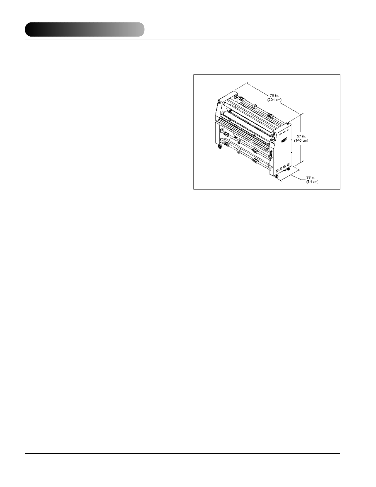
Dimensions (W x L x H):
Unit alone: (Figure 1)
79 in. x 33 in. x 57 in.
(201 cm x 84 cm x 145 cm)
Shipping:
85 in. x 44.5 in. x 78 in.
(216 cm x 113 cm x 198 cm)
Weight:
Unit alone: 1498 lb. (679 kg.)
Shipping: 1900 lb. (862 kg.)
Electrical Requirements:
Refer to the serial plate located on the rear of the
laminator for the specific electrical rating applicable
to the unit.
Voltage: 220V~60 Hz
Current: 24.5A
Power: 5500 W
Phase: Single
FCC NOTE: This equipment has been tested and
found to comply with the limits for a Class A digital
device, pursuant to part 15 of the FCC Rules.These
limits are designed to provide reasonable protection
against harmful interference when the equipment is
operated in a commercial environment. This
equipment generates, uses, and can radiate radio
frequency energy and, if not installed and used in
accordance with the instruction manual, may cause
harmful interference to radio communications.
Operation of this equipment in a residential area is
likely to cause harmful interference in which case
the user will be required to correct the interference
at his/ her own expense.
Changes or modifications not expressly approv ed by
General Binding Corporation could void the users
authority to operate the equipment.
This Class A digital apparatus complies with
Canadian ICES-003.
(Cet appareil numérique de las Classe A est
conforme a la norme NMB-003 du Canada)
Page 8

Falcon 60+ (-1)
Falcon 60+ (-1)
Operations Manual
© 2003 General Binding Corporation
Page 7
Pre- Installation
Before a Falcon 60+ (-1) Laminator can be installed,
ensure the following requirements are met;
1. Are door ways and hallways wide enough for the
laminator to be moved to the installation site?
2. Is there ample room for the laminator?
– A work area must be established that allows for
operation in both the front and rear of the laminator
and provides space for efficient material flow.
(Figure 2)
3. Is the environment appropriate for the laminator?
– The laminator requires a clean, dust and vapor
free environment to operate properly.
– Avoid locating the laminator near sources of heat
or cold. Avoid locating the laminator in the direct
path of forced, heated or cooled air.
CA
UTION: Air flow can cause uneven
heating/ cooling of the rollers and result in
poor output quality
4.Have you contacted a cer tified electrician to wire
the receptacle and ensure that adequate power is
being supplied, having the appropriate capacity,
over current protection and safety lockouts
available?
– 220V at 60hz with 25 amp service. Use the
receptacle supplied with your machine (Nema 630R).
Fig 2
Page 9
Falcon 60+ (-1)
Falcon 60+ (-1)
Fig 3
Installation
1. Shipping damage should be brought to the
immediate attention of the delivering carrier.
2. With assistance, carefully roll the laminator into
position over flat and even surfaces.
3. The laminator should be positioned to allow
exiting film to flow freely to the floor (Figure 3) or a
work table. Accumulation of laminate immediately
behind the laminator as it exits the equipment may
cause the film to wrap around the pull rollers,
resulting in a “jammed” condition.
4. Avoid locating the laminator near sources of heat
or cold. Avoid locating the laminator in the direct
path of forced, heated or cooled air.
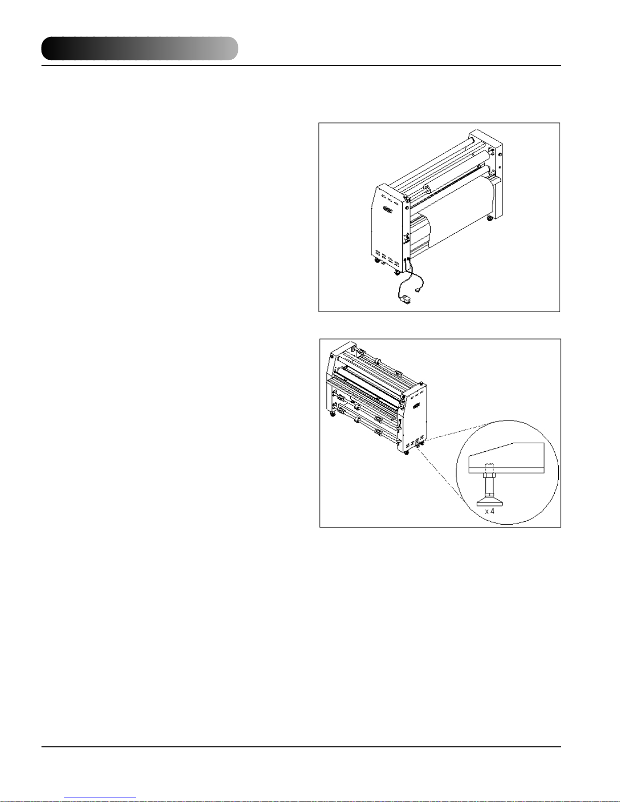
5. Leveling of the machine is a customer option. If
you choose not to level the laminator and encounter
output problems, please level the machine and try
your application again before calling for technical
support. Resting the laminator on the leveling pads
prevent the machine from rolling during set up,
operation or servicing. (Figure 4)
6. Connect the attachment plug provided with the
laminator to a suitably grounded outlet. Avoid
connecting other equipment to the same branch
circuit to which the laminator is connected, as this
may result in nuisance tripping of circuit breakers or
blowing fuses.
Operations Manual
© 2003 General Binding Corporation
Page 8
Fig 4
Page 10

Falcon 60+ (-1)
Falcon 60+ (-1)
Operations Manual
© 2003 General Binding Corporation
Page 9
Fig 5
Fig 6
Fig 7
Features Guide
A. POWER ON/ OFF:(Figure 5) Located at the back
left of the machine applies power to the laminator.
The control panel display will illuminate when
position marked “l” is pushed. The off position,
marked “O”, removes power from the laminator.
B. CONTROL PANEL INDICATORS: (Figure 6)
1. POWER INDICATOR : Illuminates when the
laminator is plugged in and POWER ON/ OFF is in
the on, (I), position.
2. PRESSURE INDICATOR : Illuminates in
increments to correspond with the amount of
pressure at the main roller nip. Pressure is
represented by percent from 0 (minimal) to 100
(maximum).
3. READY INDICATOR:“READY”Illuminates when
the actual temperature is equal to (+/- 5) set
temperature.
4. °C INDICATOR: “°C” Illuminates indicating the
displayed value is in degrees Celsius.
5. °F INDICATOR: “°F” Illuminates indicating the
displayed value is in degrees Fahrenheit.
6. ON INDICATORS : Located near the heater
and cooling fan on buttons. Illuminates when the
related on button is pressed.
7. SELECTION INDICATORS : Located near the
start/ stop and forward/ reverse buttons. Illuminates
when the selected button is pressed.
C. CONTROL PANEL BUTTONS: (Figure 7)
1. START : When pressed, indicator illuminates
and activates rollers for normal operation.
2. STOP : When pressed, indicator illuminates
and stops the movement of the rollers.
3. REVERSE : When pressed, indicator
illuminates and sets the motor direction for reverse
roller movement to clear film jams and wrap-ups.
4. FORWARD : When pressed, indicator
illuminates and sets the motor direction for forward
roller movement to run in normal operation mode.
For items 5 -13, refer to Figure 8.
Page 11

Falcon 60+ (-1)
Falcon 60+ (-1)
Operations Manual
© 2003 General Binding Corporation
Page 10
5. SPEED : This means machine roller speed.
Turn clockwise to increase speed or
counterclockwise to decrease speed. Speed range
is 1 - 10.
6. TEMPERATURE CONTROLS: The upper and
lower heaters have identical controls, on, off,
increase, decrease and measure. The top set of
controls relate to the upper heater ( ) and the lower
set of controls relate to the lower heater ( ).
7. TEMPERATURE CONTROL ON : When
pressed, indicator illuminates and turns power on to
the temperature controller unit.
8. TEMPERATURE CONTROL OFF : When
pressed, turns power off to the temperature
controller unit.
9. TEMPERATURE INCREASE : When
pressed, increases the temperature set point value.
10.TEMPERATURE DECREASE : When
pressed, decreases the temperature set point
value.
11. TEMPERATURE MEASURE: When pressed,
flashes the actual temperature of the roller.
12. COOLING ON : When pressed, indicator
illuminates and turns on the cooling fans.
13. COOLING OFF : When pressed, turns off
the cooling fans.
D. E-STOP: Four emergency stop buttons exist on
the laminator.Two located on the left and right front
and two on the left and right rear of the laminator.
(Figure 9)
To engage, push (1) any emergency stop push
button. Power to the motor is removed. To disengage, turn (2) the push button 1/4 turn
counterclockwise.
E. SAFETY SHIELD INTERLOCK LATCH: (Figure
10) Used to lock the safety shield into position and
activate an interlock switch. The interlock latch is
located on the left side of the safety shield. When
pushed to the full left (1), the safety shield is lock ed.
When pushed to the full right (2), the safety shield is
unlocked.
Fig 8
Fig 9
Fig 10
Page 12

Falcon 60+ (-1)
Falcon 60+ (-1)
Operations Manual
© 2003 General Binding Corporation
Page 11
F. SAFETY SHIELD: (Figure 11) Prevents
entanglement, entrapment and inadvertent contact
with the heat rollers. The laminator will operate
normally only when the Safety Shield is located
in the fully locked and closed position. When
shield is open, the laminator will only run at 1
mpm (approximately 3.25 ft/m).
To remove the saf ety shield, unlock the safety shield
interlock latch and lift the safety shield (1) up and
away from the safety shield mounting pins (2).
G. FEED TABLE: (Figure 12) The Feed Table is
used to position items for lamination. To pivot the
feed table, remove the safety shield, lift up on the
feed table, pull back, then carefully lower.The laminator will operate only when the Feed Table is
properly installed.
H. CHILL IDLER: (Figure 12) Assist in the cooling
process of the web material as it exits the heat
rollers.
To remove the chill idler, lift the chill idler straight up
and out from the chill idler brackets.
I. FILM SHAFT: (Figure 12) The film shaft holds the
film supply on the machine.
J. MAIN ROLLERS: (Figure 12) Silicone rubber
coated steel tubes heat the laminating film and
compress the heated film to the items being
laminated. Heat is provided by an internal heating
element. The heat rollers are motor dr iven for ease
of loading new film.
K. IDLER BAR: (Figure 13) The idler bars, located
near each heat roller, are used to direct the film to
the heat roller nip. The bottom Idler Bar is movable
to ease film loading.
L. PULL ROLLERS: (Figure 13) The pull rollers,
located at the back of the laminator, are motor
driven. They simultaneously pull the film and
improve the quality of the laminated item.
M. REWIND TUBE: (Figure 13) The front rewind
tube is used to rewind release liner while the rear
bottom rewind tube is used to rewind finished
product. To remove the rewind tube, push the tube
against the rewind brake and remove the tube from
the rewind support side.
Fig 11
Fig 12
Fig 13
Page 13

Falcon 60+ (-1)
Falcon 60+ (-1)
Operations Manual
© 2003 General Binding Corporation
Page 12
N. FILM SHAFT BRAKE: (Figure 14) Used to apply
resistance to the film shaft. One for the upper
unwind and one for each of the lower unwinds.
To increase film shaft brake, turn the film shaft brake
dial clockwise. Counter clockwise will decrease film
shaft brake tension.
O. CORE ADAPTERS: (Figure 14) Hold and lock
the rolls of film on the shafts to prevent side to side
shifting.
P. CENTER CORE SUPPORT: (Figure 14)
Supports the center of the film cores when placed
onto the unwind shafts.
Q. REWIND BRAKE: (Figure 15) Located on the
right side from the front operating position.
Turn in a forward roller direction to increase rewind
brake tension. Reverse roller direction will decrease
rewind brake tension.
R. MAIN ROLLER CRANK HANDLE: (Figure 15)
Used to raise or lower the upper main roller. Tur ning
the handle clockwise will lower the roller.
Counterclockwise will raise the roller.
NOTE:You can not raise or lower the main roller
if the feed table is in the tilted position.
S. PULL ROLLER CRANK HANDLE: (Figure 15)
Used to raise or lower the upper pull roller. Tur ning
the handle clockwise will raise the roller.
Counterclockwise will lower the roller.
T. COOLING FANS: Assist in the cooling process
by pushing unheated air onto the web material as it
exits the heated rollers. This feature can be
controlled from the control panel.
U. CLUTCH: (Figure 16) Used to increase or
decrease pull roller clutch tension. Clockwise
rotation will increase clutch tension while
counterclockwise rotation decreases clutch tension.
V. FOOTSWITCH: (Figure 16) When the Run/Stop
footswitch is pressed and all safety shields are in
place, the laminator will run at current speed setting.
With safety out, speed is reduced to 1 mpm
(approximately 3.25 ft/m).
Fig 14
Fig 15
Fig 16
Page 14

Falcon 60+ (-1)
Falcon 60+ (-1)
Operations Manual
© 2003 General Binding Corporation
Page 13
W. REAR TABLE LATCHES: (Figure 17) Located
under the left and right sides of the rear table.
X. REAR TABLE: (Figure 17) Provides a working
surface when operating the machine from the rear.
This table may also be lowered when webbing for
roll to roll applications.
To lower , pull the left and right side rear table latches
in and lower the rear table.
Y. REAR RUN/ STOP SWITCH: (Figure 18)
Located on the right side of the laminator from the
rear operating position.This switch permits run (1) /
stop (2) control of the motor from the rear operating
position.
Z. FILM WEB: Laminating film loaded into the
machine.
a. NIP POINT: The point at which the top and
bottom rollers come into contact. The Nip Point of
the heat rollers is the place at which the items for
lamination are introduced into the laminator.
b. REAR SLITTER: (Figure 19) Used to cut off the
laminated web. To use, push down on the blade
engage lever (1) and slide across the rear slitter rail
(2) to the opposite side.
c. SEPARATOR BAR: (Option) (Figure 19)
Required if running Accushield™ material.To install,
remove the rear slitter and position the separator bar
in it’s place.
(Falcon 60+ (-1) Part # 2020577)
Fig 17
Fig 18
Fig 19
Page 15

Falcon 60+ (-1)
Falcon 60+ (-1)
Operations Manual
© 2003 General Binding Corporation
Page 14
Operating Instructions
Film Loading & Threading
The top and bottom rolls of laminating film must be
of the same width and be present simultaneously. A
small amount of adhesive will “squeeze out” during
lamination. Hardened adhesive deposits can
damage the heat rollers. To avoid any damage,
select “Low-Prs LAMI.” for job mode ( ), rotate the
rollers at slowest speed with heat on. Refer to the
section entitled CARING FOR THE FALCON 60
+ (-1) LAMINATOR for instructions regarding
removal of the accumulated adhesive.
Adhesive will deposit on the rollers if:
- Only one roll is used.
- Different widths of rolls are loaded together.
- Either roll is loaded adhesive side against a heat
roller.
- One or both rolls of film are allowed to run
completely off its core.
The adhesive side of the film is on the inner side of
the web (Figure 20). The shiny side of clear film
must contact the heat rollers.The dull side of the film
contains the adhesive. Use extreme caution when
loading delustered (matte) film as both sides appear
dull.
Always change the top and bottom supply rolls at
the same time. Near the end of each roll of GBC
laminating film is a label stating “Warning-End of
Roll”.The appearance of this label on either the top
or bottom roll requires that new rolls of film be
installed as soon as the item presently being
laminated completely exits the rear of the laminator.
Do not introduce any additional items into the
laminator when the warning label is visible.
To load a roll of film; (Figure 21)
1. Pull the clevis pin up.
2. Swing shaft outward.
3. Slide the roll of film onto the film shaft ensuring
adhesive side is out.
4. Push the film shaft back into the film shaft
support saddle.
5. Push the clevis pin down.
6. Center the roll of film.
Fig 20
Fig 21
Page 16

Falcon 60+ (-1)
Falcon 60+ (-1)
Operations Manual
© 2003 General Binding Corporation
Page 15
Webbing Thermal Film Using
Threading Card
The following procedure uses the film threading card
provided with new rolls of GBC film. The laminator
rollers will be hot for this procedure. For pressure
sensitive film (PSA), refer to the section entitled
WEBBING USING FILM THREADING CARD FOR
PSA FILM.
1. Turn the Power ON/OFF to on (I).
2. Set top and bottom temperature with regards to
the film type used.
3. Ensure no brake tension is applied to the film
shafts.
4. Remove the safety shield and pivot the feed table
down.
5. Pull the top roll of film down under the upper idler
bar and allow to drape over the top heat roller
(Figure 22).
6. Pull the lower film behind the lower idler bar and
up towards the film draped over the top heat roller
(Figure 23).
7. Use a threading card to push the two materials
into the heat roller nip.
8. Pivot the table back to it’s feeding position while
ensuring the threading card is on top of the feed
table (Figure 24).
9. Use the main roller pressure handle to bring the
main roller to initial contact with the threading card.
10. Replace the safety shield.
11. Set speed to 3 or less.
12. Ensure forward ( ) is selected for motor
direction and press the start ( ) button.
13. From the rear of the machine, guide the web
over the chill idler, if installed, and through the pull
rollers.
14. Once the web has entered the pull roller nip, use
the pull roller pressure handle to close the pull roller
nip.
15. Once the threading card has completely exited
the pull rollers, press the stop ( ) button.
16. Open the main roller nip.
17. Now refer to the section entitled START
LAMINATING.
Fig 22
Fig 23
Fig 24
Page 17

Falcon 60+ (-1)
Falcon 60+ (-1)
Operations Manual
© 2003 General Binding Corporation
Page 16
Webbing PSA Film/Mount Adhesive
Using Threading Card
The laminator should be cool to the touch before
proceeding.
1. Turn the Power ON/OFF to on (I).
2. Load the rolls of film as illustrated in Figure 25.
Ensure no brake tension is applied to the film shafts.
3. Remove the safety shield and pivot the feed table
down.
4. Pull the top roll of film down under the idler bar
and up to the upper front rewind tube.
5. Place one piece of masking tape in the center of
the film and secure to the rewind tube.
6. Make two full wraps around the rewind tube, then
carefully score the laminate without cutting the
release liner. Pull the laminate down allowing it to
drape over the upper heat roller (Figure 25).
7. Pull the mount adhesive up towards the film
draped over the upper heat roller (Figure 26).
8. Use a threading card to push the two materials
through the heat roller nip.
9. Pivot the table back to it’s feeding position while
ensuring the threading card is on top of the feed
table (Figure 27).
10. Replace the safety shield.
11. Use the main roller pressure handle to bring the
main roller to initial contact with the threading card.
Set speed to 3 or less.
12. Set speed to 3 or less. Ensure forward ( ) is
selected and press the start ( ) button.
13. From the rear of the machine, guide the web
over the chill idler, if installed, and through the pull
rollers.
14. Once the web has entered the pull roller nip, use
the pull roller pressure handle to close the pull roller
nip.
15. Press the stop ( ) button Once the threading
card has completely exited the pull rollers,.
16. Open the main roller nip.
17. Now refer to the section entitled START
LAMINATING.
Fig 25
Fig 26
Fig 27
Page 18

Falcon 60+ (-1)
Falcon 60+ (-1)
Operations Manual
© 2003 General Binding Corporation
Page 17
Start Laminating
1. At this point you should have your laminator
webbed with the appropriate material for your
application.
2. The safety shield and feed table should be in the
normal operating position.
3. The main rollers should be open and the pull
rollers should be closed.
4. Speed is set to 3 or less and forward () motor
direction is selected .
5. Press the start () button.
6. Set main roller pressure between 40 - 50% for
laminating.
CA
UTION: If using PSA film, an air pocket
may result between the main rollers and pull
rollers. Raise the pull rollers to allow the air
pocket to pass.
7. Make any necessary film brake tension, pull/
main roller pressure, clutch and/ or rewind brake
tension adjustments. Refer to the section entitled
SPEED/ TEMPERA TURE GUIDE.
8. Position the item to be laminated on the feed
table.
9. Align the leading edge of the item square to the
heat roller nip (Figure 28).
10. With both hands and an outward force push the
image slower than the speed of the rollers into the
nip of the heat rollers (Figure 29).
CA
UTION:
Avoid forcing the image into the
main roller nip as this action will cause the
corners of the leading edge to buckle and
create a wave.
Fig 28
Fig 29
Page 19

Falcon 60+ (-1)
Falcon 60+ (-1)
Operations Manual
© 2003 General Binding Corporation
Page 18
Method For Tacking New Film To
Existing Film
The following describes a method for loading film
whereby the existing film present on the heat rollers
may be used in place of the threading card to draw
the new film through the laminator. The adhesive of
the existing film must be tacky or liquefied.Leading
edges of the new film will be overlapped onto the
tacky adhesive of the old film.The existing film and
the new film will be pulled through the laminator
together.
1. Cut (1) remaining top film web between the idler
bar and heat roller.Cut (2) the film web between the
lower film supply and the idler bar (Figure 30).
CA
UTION: Be careful not to cut any of the rollers!
2. Remove the safety shield and tilt the feed table
down.
3. Do not allow the adhesive side of the film to
contact the heat or pull rollers. Liquefied or tacky
adhesive deposited on heat rollers will require the
rollers to be cleaned per the section entitled
CARING FOR THE FALCON 60+(-1) LAMINATOR.
4. Replace both the top and bottom rolls of film with
new rolls.Ensure the adhesive side is facing out.
5. Pull the film around the idler bars, with the
exception of PSA mounting adhesives without a
release liner.
6. Tack the new film to the existing film on the heat
rollers. For PSA film, attach the release liner to the
rewind tube (Figure 31).
7. Use the footswitch to advance the film into the
heat roller nip.
8. Observe the film being pulled through the
laminator to assure that the remaining existing film
and the new film are advancing concurrently. Any
separation between the films will require stopping
the motor immediately and the situation corrected.
9. Press STOP ( ) once the newly threaded film
has completely exited the pull rollers.
Fig 30
Fig 31
Page 20

Falcon 60+ (-1)
Falcon 60+ (-1)
Operations Manual
© 2003 General Binding Corporation
Page 19
To Unwed the laminator
Unweb the laminator if you are changing film widths,
cleaning the rollers or have finished using the
machine for the day.
1. Using the rear slitter, cut (1) the output from the
web (Figure 32).
2. Cut (2) remaining top film web between the idler
bar and heat roller. PSA film, cut the release liner
too.
3. Cut (3) the film web between the lower film supply
and the idler bar (Figure 32).
CA
UTION: Be careful not to cut any of the rollers!
4. Remove the safety shield and tilt the feed table.
5. Gap the main rollers and pull rollers.
6. Carefully grab hold of the web (top and bottom
film), from the front operating position and pull
towards you (Figure 33).
7. Do not allow the adhesive side of the film to
contact the heat or pull rollers.
Clearing a Film Jam (Wrap-up)
Film jams (wrap-ups) may occur if the film is loaded
backwards or if the area at which film exits the
equipment is blocked. The film, when jammed,
wraps around the heat rollers during webbing if a
threading card is not used or pull rollers during
operation.
To clear a jam:
1. Immediately stop the laminator by pressing
STOP ( ).
2. Remove the safety shield and tilt the feed table.
3. Set motor direction to reverse.
4. Use the footswitch to reverse the web until the
wrap up is clear.
5. Raise the main roller and pull rollers.
6. Manually guide the web from the main rollers and
pull rollers.
7. Once the film jam has been cleared, lower the
main roller and pull rollers.
8. Refer to the section titled START LAMINATING.
Fig 32
Fig 33
Page 21

Falcon 60+ (-1)
Falcon 60+ (-1)
Operations Manual
© 2003 General Binding Corporation
Page 20
Applications
Tips For Pre Coating Boards
(Figure 34)
1. Load the laminator as illustrated in Figure 34.
Remove chill idler.
2. The width of the roll should not exceed the width
of the board by more than 1/2 in. (1.3 cm).
3. Use a leader board to set the main roller and pull
roller pressure prior to webbing.
4. Use a leader board to start the r un and a trailer
board to finish the run.
5. Using the pull rollers will allow you to leave gaps
between boards.
6. If not using the pull rollers, have the boards
nearby to butt end to end during feeding.
Tips For Mounting Pre Coated Boards
(Figure 35)
1. This application can also be performed from the
rear operating position. Reference Figure 38 for
illustration.
2. Use a leader board to set the main roller pressure
prior to mounting the image.
3. Ensure the chill idler is removed and the rear
slitter is to one side.
4. Heat, 125 OF (52 OC), may assist the process
and increase output quality.
5. Do not stop once you have started the mounting
process through the machine.
Tips For Single Sided lamination
(Figure 36)
1. Load the laminator as illustrated in Figure 36.
2. Use kraft paper for one-sided lamination
whenever the items to be laminated are narrower
than the film you are using.
3. If not using kraft paper, use a scrap piece to finish
the run or you will have adhesive on your rollers.
4. For high volume runs, use Kraft paper and the
lower rear rewind for roll to roll operation.
5. Running the web over the chill idler may improve
Fig 34
Fig 35
Fig 36
Page 22

Falcon 60+ (-1)
Falcon 60+ (-1)
Operations Manual
© 2003 General Binding Corporation
Page 21
Tips For Creating a Decal
(Figure 37)
1. Load the laminator as illustrated in Figure 37.
2. The over laminate may be PSA or thermal type.
3. If using thermal type, pay attention to the Poly-in/
Poly-out rule.
4. Run a test material prior to running the actual
image to ensure flat output.
5. Use minimal brake tension to achieve quality
output.
6. Do not web the PSA mount adhesive around the
lower web idler.
Tips for mounting a Decal
(Figure 38)
1. This application can also be performed from the
front operating position. Reference Figure 35 for
illustration.
2. Use a leader board to set the pull roller pressure
prior to mounting the image.
3. The image should not exceed the width of the
board by more than 1 in. (2.54 cm) per side.
4. Tack about 1 in. (2.54 cm) of the leading edge of
the decal to the leading edge of the board.
5. When tacking the leading edge, start in the center
and work to the sides.
6. Use a board that exceeds the size of the decal if
inexperienced in the mounting application.
Tips For Thermal Encapsulation
(Figure 39)
1. Load the laminator as illustrated in Figure 39.
Poly-in film is used for illustration purpose.
2. Refer to section entitled FILM LOADING &
THREADING for Poly-out film.
3. Always use two rolls of film the same width.
4. Use minimal brake tension to achieve flat output.
5. Increase speed gradually to maintain the
activating temperature required for the laminate you
are using.
6. Length and width of image, ink coverage and
paper type may effect the temperature and speed
recommended in the SPEED/ TEMPERATURE
GUIDE.
Fig 37
Fig 38
Fig 39
Page 23

Falcon 60+ (-1)
Falcon 60+ (-1)
Operations Manual
© 2003 General Binding Corporation
Page 22
Tips for ACCUSHIELD
(Figure 40)
1. Load the laminator as illustrated in Figure 40.
2. You must have the Separator bar option to
accurately run this material.
3. Set Top Temp. to 265 OF (129 OC) and a speed
setting no greater than 4.
4. Liner rewind tension will be greater than normal
operating standards.
5. To prevent some adhesive adhering to the rollers,
you may choose to use a roll of kraft paper for a
carrier.
Use the blank space below and blank diagrams to
note your tips and web paths for your special
applications.
TIPS FOR CUSTOM APPLICATION #1 (Figure 41)
1.
2.
3.
4.
TIPS FOR CUSTOM APPLICATION #2 (Figure 42)
1.
2.
3.
4.
5.
Fig 40
Fig 41
Fig 42
Page 24

Falcon 60+ (-1)
Falcon 60+ (-1)
Operations Manual
© 2003 General Binding Corporation
Page 23
Fig 43
Fig 44
Speed /Temperature Control
This is only a general reference guide. Different
settings may be suitable as the warm up time,
lamination time and materials change. (Figure 46
& 47)
Factors that may effect the speed and temperature
parameters;
1. Image length
2. Image width
3. Ink coverage
4. Paper type
5. Laminate thickness
6. Operating environment
7. Condition of the rollers
8. Line voltage (effects heaters)
9. Using cooling features.
You may have to adjust temperature
or speed depending on stock finish, thickness and
ink coverage.
*Turn heat off when not in use.
Stock
20#
Bond
80#
Bond
Film
Gauge
mil
1.5
3
5
10
1.5
3
5
10
Nap-Lam II
Settings
Temp (F) Speed SpeedTemp (F)
248
239
230
221
248
239
230
221
8
6
5
3
6
5
3
2
Nap-Lam I
Settings
290
270
250
295
275
250
*Vinyl
Settings
SpeedTemp (F) SpeedTemp (F)
7
5
3
7
5
2
230
230
5
3
Premium
Settings
225
220
210
230
225
215
SpeedTemp (F)
4
3
3
4
3
3
Hi-Tac
Settings
255
255
8
6
10 Pt.
Board
Stock
20#
Bond
80#
Bond
10 Pt.
Board
1.5
3
5
10
Film
Gauge
mic
38
75
125
250
38
75
125
250
38
75
125
250
248
239
230
221
Nap-Lam II
Settings
Temp (C) Speed SpeedTemp (C)
120
115
110
105
120
115
110
105
120
115
110
105
5
4
2
2
8
6
5
3
6
5
3
2
5
4
2
2
300
275
250
Nap-Lam I
Settings
143
132
121
146
135
121
149
135
121
6
4
2
7
5
3
7
5
2
6
4
2
230
*Vinyl
Settings
110
110
110
235
2
SpeedTemp (C) SpeedTemp (C)
5
3
2
230
220
Premium
Settings
107
104
99
110
107
107
112
110
104
4
3
2
SpeedTemp (C)
4
3
3
4
3
3
4
3
2
255
Hi-Tac
Settings
123
123
123
4
8
6
4
Page 25

Falcon 60+ (-1)
Falcon 60+ (-1)
Operations Manual
© 2003 General Binding Corporation
Page 24
The Art of lamination
Basic Rules
Do not attempt to laminate abrasive or metal
objects such as staples, paper clips and glitter,
as they may damage the heat or pull rollers.
Do not force items into the nip area of the heat
rollers. An item that is not easily drawn into the
laminator by the heat rollers is probably too
thick to laminate.
Wrinkles may result if an attempt is made to
reposition an item once it has been grasped by
the heat rollers.
Do not stop the laminator before an item has
completely exited the pull rollers. Even a
momentary stop will cause a mark (heat line) on
the laminated item.
Good, consistent lamination is a result of combining
proper heat, tension and dwell time. Dwell time is
controlled by the speed of the motor and is defined
as the amount of time the material to be laminated
is compressed between the heat rollers.
As a general rule, thicker items and film need to run
at slower speeds because they extract more heat
from the rollers at a quicker rate. Setting the speed
control at slower settings gives the laminator longer
dwell time thus allowing proper lamination of thick
items. Thinner items, such as standard copier paper
(20 lb.bond) and tissue paper , e xtract less heat from
the rollers and can be run at faster speeds.
FILM TENSION
Proper film tension, known as brake tension, is the
minimum amount required to eliminate wrinkles in
the finished item.The film should be taut.A properly
adjusted roll of film should not require excessive
force to turn by hand.
Film tension should be enough to introduce a minor
amount of drag as the film unrolls. Insufficient
tension causes wrinkles, while too much tension
causes stretching (necking). Uneven tension
between the top and bottom rolls create curl. Too
much upper tension creates upward curl while too
much bottom tension causes downward curl.
Adjustment of the pull roller clutch may be
necessary if after adjusting unwind and rewind
brake tensions do not improve your output quality.
Page 26

Falcon 60+ (-1)
Falcon 60+ (-1)
Operations Manual
© 2003 General Binding Corporation
Page 25
Heat
The “READY” indicator may extinguish if the speed
is set too fast for the material being laminated.
Either lower the speed setting or press STOP and
wait until the “READY” indicator illuminates.
Operation of the laminator for more than thirty
minutes at a time may necessitate a lower speed
setting. It is recommended that, during periods of
long runs, the items being laminated are alternated
between thick and thin. Do not combine thick and
thin items at the same time, as this will result in a
poor edge seal around the thinner material. If you
are unsure that the laminator is set at the proper
speed for the item to be laminated, run a test piece
(scrap) of the same or similar material through the
laminator. This procedure is recommended
because rotating the heat roller prior to lamination
will more evenly distribute the heat. Make speed
adjustments if necessary.
Output
1. “D” waves in the image (Figure 45 A).
– Check paper tension.
– Paper may be damp or not dr y.
2. “D” waves in the laminate (Figure 45 B).
– Check main roller pressure.
– Check pull roller pressure.
3. Straight waves in output (Figure 46 A).
– Check operational settings for materials
being used.
– Check clutch tension.
4. Indent waves in output after pull rollers
(Figure 46 B).
– Insufficient cooling time.
– Output was handled prior to cooling.
– Use cooling feature if not on.
– Machine was stopped on print.
5. Angled waves in the output
(Figure 47 A & B).
– Main air supply setting.
– Check main roller pressure.
– Check pull roller pressure.
– Check for even paper tension. (Figure 49 A only)
Fig 45
Fig 46
Fig 47
Page 27

Falcon 60+ (-1)
Falcon 60+ (-1)
Operations Manual
© 2003 General Binding Corporation
Page 26
Maintenance
Caring For The GBC Falcon 60+ (-1)
Laminator
GBC offers Cleaning kits as well as Extended
Maintenance Agreements.
Contact your local GBC Service Representative or
your dealer/distributor for additional information.
The only maintenance required by the operator is to
periodically clean the heat rollers and schedule semi
annual maintenance checks.
The following procedure will help keep the heat
rollers free of adhesive that has been deposited
along the edge of the laminating film. Proper
alignment of the rolls of film reduces the amount of
“squeeze out”.
W
ARNING: Do not attempt to laminate
adhesives marked “Flammable”.
• Do not laminate glitter and/ or metallic items.
Damage to the rollers may result.
W
ARNING: Do not apply any cleaning fluids
or solvents to the rollers. Some solvents and
fluids could ignite on heated rollers.
• Never clean rollers with sharp or pointed objects.
• Hardened adhesive deposits on the rollers can
cause damage to the rollers.Rotate the rollers at the
lowest speed setting on the control panel.
CAUTION:THE FOLLOWING PROCEDURE
IS PERFORMED WHILE THE LAMINATOR
IS HOT. USE EXTREME CAUTION.
1. Remove the film from the laminator following the
procedure outlined in steps 1 through 6 of the
section entitled TO UNWEB THE LAMINATOR.
2. Preheat the laminator until the “READY ”indicator
illuminates.
3. Remove the safety shield and tilt the feed table.
4. Rub the top and bottom heat rollers with a 3M™
Scotch-Brite™ pad . DO NOT USE METAL
SCOURING PADS!
5. Use the footswitch to rotate the lower heat/ pull
roller to an unclean portion. The upper heat/ pull
roller are free spinning. Continue this process until
the complete surface of both rollers are clean.
6. Refer to the beginning of the section entitled
OPERATING INSTRUCTIONS to web your
laminator.
*NOTE: Do not use metal scouring pads to clean
the rollers.
 Loading...