

Page 1
F - 160 OPERATION AND
MAINTENANCE MANUAL
© November 1999 GBC Pro-Tech
Do not duplicate without written permission.
Plane4
Plane4
Plane4
GBC Pro - Tech
4151 Anderson Road
DeForest, WI 53532
Revision : B Ph: ( 608 ) 246 - 8844
Part number : 930 - 031
Fx: ( 608 ) 246 - 8645
Page 2

F - 160 Operation and Maintenance Manual Read me file
Read Me File . . . . . . . . .
The information in this publication is provided for reference and is believed to be
accurate and complete. GBC Pro - Tech is not liable for errors in this publication or for
incidental or consequential damage in connection with the furnishing or use of the information
in this publication, including, but not limited to, any implied warranty of fitness or merchantability for any particular use.
GBC Pro - Tech reserves the right to make changes to this publication and to the products described in it without notice. All specifications and information concerning products are
subject to change without notice.
Reference in this publication to information or products protected by copyright or
patent does not convey any license under the rights of GBC Pro - Tech or others. GBC Pro T ech assumes no liability arising from infringements of patents or any other rights of third
parties.
This publication is copyrighted © 1999 by GBC Pro - Tech. All rights reserved. The
information contained in this publication is proprietary and may not be reproduced, stored,
transmitted, or transferred, in whole or in part, in any form without the prior and express
written permission of GBC Pro - Tech.
In the electronic version of this publication, the hand will change to a pointer finger
identifying hyperlinked. When moving from page to page, use
P AGE, use
to advance one PAGE. When moving from view to view, use to return to a previous
VIEW and use
Should you find an error within this publication or would like to make a suggestion,
please utilize the fax correspondence sheet following this read me file and fax it to the number
provided. Your comments and help will ensure up to date information. Thank you.
to advance to the last PAGE, use to go back one PAGE and use
to advance to the next VIEW.
to return to the first
© GBC Pro - Tech August 1999
Page 3

This page intentionally left blank.
F - 160 Operation and Maintenance ManualRead me file
© GBC Pro - Tech August 1999
Page 4

F - 160 Operation and Maintenance Manual Read me file
Fax Correspondence
Fax number : ( 608 ) 246 - 8645 Date :
To : Sean Flood @ GBC Pro - Tech
4151 Anderson Road
DeForest, WI 53532
From :
Company :
Address :
Phone number : ( ) Fax number : ( )
Re : Falcon 160 Operations and Maintenance Manual ( Rev. A )
What section ? What Page # ?
What needs correcting ?
Additional comments:
© GBC Pro - Tech August 1999
Page 5

This page intentionally left blank.
F - 160 Operation and Maintenance ManualRead me file
© GBC Pro - Tech August 1999
Page 6

F - 160 Operation and Maintenance Manual
Table of Contents
Section 1: Safety
1.1 Symbols ......................................................................................................1 - 1
1.2 Safety features ...........................................................................................1 - 1
1.3 Installation .................................................................................................1 - 4
1.4 Operations ..................................................................................................1 - 8
T able of Contents
1.5 Applications ..............................................................................................1 - 12
1.6 Troubleshooting .......................................................................................1 - 16
1.7 Maintenance .............................................................................................1 - 16
1.8 Decal Explanation ....................................................................................1 - 19
Figure 1 - 6 Decal Location .......................................................1 - 20
Section 2: Warranty
2.1 Limited warranty information ...................................................................2 - 1
2.2 Exclusions to the warranty .......................................................................2 - 1
© GBC Pro - Tech August 1999 Page I
Page 7

T able of Contents
Section 3: Specifications
3.1 General .......................................................................................................3 -1
3.2 Consumables ..............................................................................................3 - 1
3.3 Function .....................................................................................................3 - 2
3.4 Electrical ...................................................................................................3 - 2
F - 160 Operation and Maintenance Manual
3.5 Dimensions ................................................................................................3 - 3
Figure 3.5.1 Dimensions ...............................................................3 - 3
Section 4: Installation
4.1 Preinstallation check list ...........................................................................4 - 1
Figure 4.1.1 Suggested floor layout .............................................4 - 3
Figure 4.1.2 Single phase ( U.S. ) ................................................4 - 4
Figure 4.1.3 Three phase ( Europe ) ...........................................4 - 4
4.2 Unpacking .................................................................................................4 - 5
© GBC Pro - Tech August 1999Page II
Page 8

F - 160 Operation and Maintenance Manual
4.3 Shrink wrapped ........................................................................................4 - 5
4.4 Crated ........................................................................................................4 - 6
4.5 Accessory pack content ............................................................................4 - 8
4.6 Leveling .....................................................................................................4 - 8
4.7 Safety check ............................................................................................4 - 11
T able of Contents
4.7.1 Front and rear infeed tables ................................................................4 - 12
4.7.2 Front and rear safety shields ...............................................................4 - 14
4.7.3 Emergency stops ..................................................................................4 - 15
4.8 Function check ........................................................................................4 - 17
4.8.1 Control panel .......................................................................................4 - 18
Figure 4.8.1 Default settings ......................................................4 - 21
4.8.2 Variable speed footswitch ....................................................................4 - 22
4.8.3 Unwind shafts and unwind brakes .......................................................4 - 22
© GBC Pro - Tech August 1999 Page III
Page 9

T able of Contents
Section 5: Operations
5.1 Control panel .............................................................................................5 - 1
Figure 5.1.1 Front control panel ................................................5 - 9
5.2 Emergency ...............................................................................................5 - 10
5.3 Set up .......................................................................................................5 - 11
F - 160 Operation and Maintenance Manual
5.3.1 Power ....................................................................................................5 - 11
5.3.2 Film loading ..........................................................................................5 - 12
Figure 5.3.4 Measurement chart ................................................5 - 13
5.3.5 Heating .................................................................................................5 - 13
5.4 Job programming ...................................................................................5 - 15
Figure 5.4.1 Job save chart ......................................................5 - 17
5.5 Manual nip adjustment ...........................................................................5 - 17
5.5.1 Main roller manual nip adjustment .....................................................5 - 17
5.5.2 Pull roller manual nip adjustment ........................................................5 - 20
© GBC Pro - Tech August 1999Page IV
Page 10

F - 160 Operation and Maintenance Manual
5.6 Infeed tables ............................................................................................5 - 23
5.6.1 Removing the infeed tables ..................................................................5 - 23
5.6.2 Replacing the infeed tables ..................................................................5 - 23
Section 6: Applications
T able of Contents
Group 1: No heat
6.1 Precoating substrates ...............................................................................6 - 1
6.2 Mounting only .........................................................................................6 - 10
6.3 Single sided lamination ( Sled method ) ..................................................6 - 17
6.4 Single sided lamination ( Craft paper method ) ......................................6 - 25
6.5 Decal and mount .....................................................................................6 - 34
Pass 1 Decal ........................................................................................6 - 34
Pass 2 Mount .......................................................................................6 - 43
© GBC Pro - Tech August 1999 Page V
Page 11

T able of Contents
6.6 Precoating substrates ..............................................................................6 - 51
6.7 One pass mount and laminate .................................................................6 - 60
6.8 Thermal decal and mount .......................................................................6 - 69
Pass 1 Thermal decal ...........................................................................6 - 70
F - 160 Operation and Maintenance Manual
Group 2: Top heat only
Pass 2 Mount ........................................................................................6 - 78
Group 3: Top and bottom heat
6.9 Encapsulation ...........................................................................................6 - 85
6.10 Parameter charts and diagrams
Figure 6.10.1 Temperature conversion chart ...................6 - 95
Blank chart ....................................................................................................6 - 96
Blank diagram ...............................................................................................6 - 97
Chart 1 - Precoating substrates .....................................................................6 - 98
© GBC Pro - Tech August 1999Page VI
Page 12

F - 160 Operation and Maintenance Manual
Diagram 1 - Precoating subtrates .................................................................6 - 99
Chart 2 - Mounting only ...............................................................................6 - 100
Diagram 2 - Mounting only .........................................................................6 - 101
Chart 3 - Single sided ( Sled ) ......................................................................6 - 102
Diagram 3 - Single sided ( Sled ) .................................................................6 - 103
T able of Contents
Chart 4 - Single sided ( Craft paper ) ..........................................................6 - 104
Diagram 4 - Single sided ( Craft paper ) .....................................................6 - 105
Chart 5 - Decal and mount ( Decal ) ...........................................................6 - 106
Diagram 5 - Decal and mount ( Decal ) ......................................................6 - 107
Chart 6 - Decal and mount ( Mount ) .........................................................6 - 108
Diagram 6 - Decal and mount ( Mount ) ....................................................6 - 109
Chart 7 - Precoating subtrates ....................................................................6 - 110
Diagram 7 - Precoating subtrates ................................................................6 - 111
Chart 8 - One pass mount ............................................................................6 - 112
© GBC Pro - Tech August 1999 Page VII
Page 13

T able of Contents
Diagram 8 - One pass mount .......................................................................6 - 113
Chart 9 - Thermal decal and mount ( Decal ) .............................................6 - 114
Diagram 9 - Thermal decal and mount ( Decal ) ........................................6 - 115
Chart 10 - Thermal decal and mount ( Mount ) ..........................................6 - 116
Diagram 10 - Thermal decal and mount ( Mount ) .....................................6 - 117
F - 160 Operation and Maintenance Manual
Chart 11 - Encapsulation .............................................................................6 - 118
Diagram 11 - Encapsulation ........................................................................6 - 119
Section 7: Troubleshooting
7.1 Wave problems .........................................................................................7 - 1
7.2 Film problems ...........................................................................................7 - 3
7.2.1 Thermal laminates .................................................................................7 - 3
7.2.2 Pressure senstive ....................................................................................7 - 3
7.3 Machine problems .....................................................................................7 - 4
© GBC Pro - Tech August 1999Page VIII
Page 14

F - 160 Operation and Maintenance Manual
7.4 Glossary ....................................................................................................7 - 5
Section 8: Maintenance
8.1 Maintenance schedule ...............................................................................8 - 1
8.2 Cleaning the rollers ..................................................................................8 - 2
8.2.1 Cabinets and covers ...............................................................................8 - 6
T able of Contents
8.2.2 Touch screen control panel ....................................................................8 - 6
© GBC Pro - Tech August 1999 Page IX
Page 15

T able of Contents
This page is intentionally left blank
F - 160 Operation and Maintenance Manual
© GBC Pro - Tech August 1999Page X
Page 16
F - 160 Operation and Maintenance Manual
Section 1 Safety
CAUTION
Do not attempt to operate your Falcon 160
laminator until you have read this section
carefully!
Safety
WARNING
Indicates a potentially hazardous situation
which, if not avoided, could result in serious
injury.
Y our safety , as well as the safety of others, is
important to GBC Pro - T ech. This section contains
important safety information.
The following symbols are used throughout this
manual to indicate Information, Caution, W arning,
Danger and Electrical Shock conditions.
1.1 Symbols
INFORMATION
DANGER
Indicates an imminently hazardous situation
which, if not avoided, could result in death
or serious injury.
ELECTRICAL
SHOCK
Indicates an electrical shock situation which,
if not avoided, could result in serious
paralyzation of the body or death.
Indicates helpful information that should be
considered before, during, or after an
action, step or procedure is given.
1.2 Safety features
CAUTION
The F-160 laminator has been designed with
Indicates a potentially hazardous situation
which, if not avoided, could result in minor
or moderate injury, or alerts against unsafe
practices or alerts against actions which
could damage the product.
© GBC Pro - Tech August 1999 Page 1 - 1
safety as a primary consideration; however, you
must become thoroughly familiar with the controls,
proper operation, proper service procedures and safety
features of the laminator before using or servicing the
unit.
Page 17
Safety F - 160 Operation and Maintenance Manual
Cabi
GBC Pro - T ech laminators are powerful
machines that are designed to mount, laminate, and
encapsulate. The forces required to accomplish these
tasks can vary from negligible to very large.
The motorized main roll lift mechanism used to
provide downward pressure on the top roll is capable
of producing forces greater than 400 pounds. This force
is applied to any object presented in the opening (
called the nip ) between the two rolls.
Use care in lowering the top laminating roll and
know how to react quickly in an emergency . The main
laminator roll up / down control is located on the right
side of the machine within the front control panel. The
GAP up / down arrows controls the motion of the top
main laminating roll. Before pressing the GAP down
arrow , ensure that nothing is in the nip area.
The word qualified is defined below;
Qualified ;
• Any engineer that has experience with
electrical and mechanical design of lamination
equipment.The engineers should be fully aware of all
aspects of safety with regards to lamination equipment.
• Any commissioning or service engineer must
be of competent nature, trained and qualified to GBC
Pro-T ech standards to fulfill that job. This person will
have completed and passed the full service training
course from GBC Pro-T ech.
• Any GBC T echnician, GBC Specialist, and /
or GBC Pro-T ech Technician that has been through the
GBC Pro-T ech service training course.
In addition, the main laminating rolls of the F160 can reach temperatures of over 200oF
( 100oC ).
DANGER
At these temperatures there is a danger of
severe burn if the rolls are touched during
setup, operation or servicing.
INFORMATION
The F-160 laminator has steel cabinets and leg
panels that are bolted close to isolate the electrical and
drive system components for the safety of the operator.
Figure 1.2.1 illustrates placement of the cabinets and
covers.
Figure 1.2.1 Cabinets and covers
nets
Plane4
Plane4
Only a qualified service technician should
perform any procedure in Part B of this
manual.
Covers
© GBC Pro - Tech August 1999Page 1 - 2
Page 18
F - 160 Operation and Maintenance Manual
Safety
An important feature of the F-160 laminator are
the safety shields, when raised, the auto run is disabled
and drive control is transferred to the footswitch.
Figure 1.2.2 illustrates the safety shields in the up
position.
WARNING
Caution should always be exercised
when using the laminator with
the safety shields raised.
You can be seriously HURT or INJURED!
Figure 1.2.3 Emergency stops
Emergency stop
buttons
Plane4
Plane4
Plane4
Figure 1.2.2 Safety shields raised
Rear safety
shield
Front safety
shield
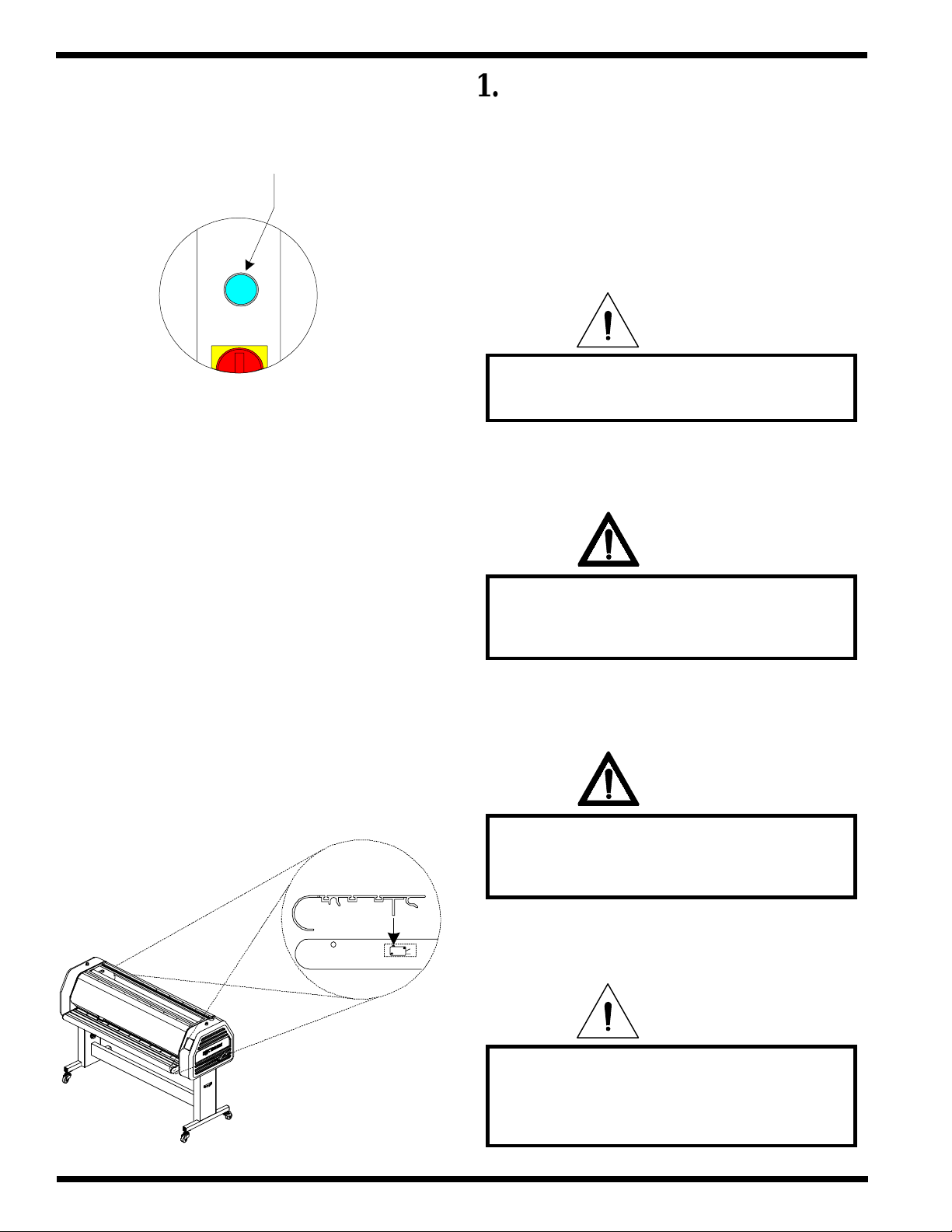
T o continue operation, both EMERGENCY
STOPS ( E-STOPS ) must be in the up position. T o
reset the E-STOP , twist the button 1/4 turn clockwise.
Refer to Figure 1.2.4 for illustration.
Figure 1.2.4 Reset E-Stop buttons
Unlatch
The laminator is equipped with two
EMERGENCY STOPS located on the top of either
side of the laminator. T o engage the EMERGENCY
STOP feature, press down on either one. Either of
these, when engaged, stops the laminator. Refer to
Figure 1.2.3 for illustration.
© GBC Pro - Tech August 1999 Page 1 - 3
Page 19
Safety F - 160 Operation and Maintenance Manual
Press RESET located on the left leg at the rear
of the machine.
Reset
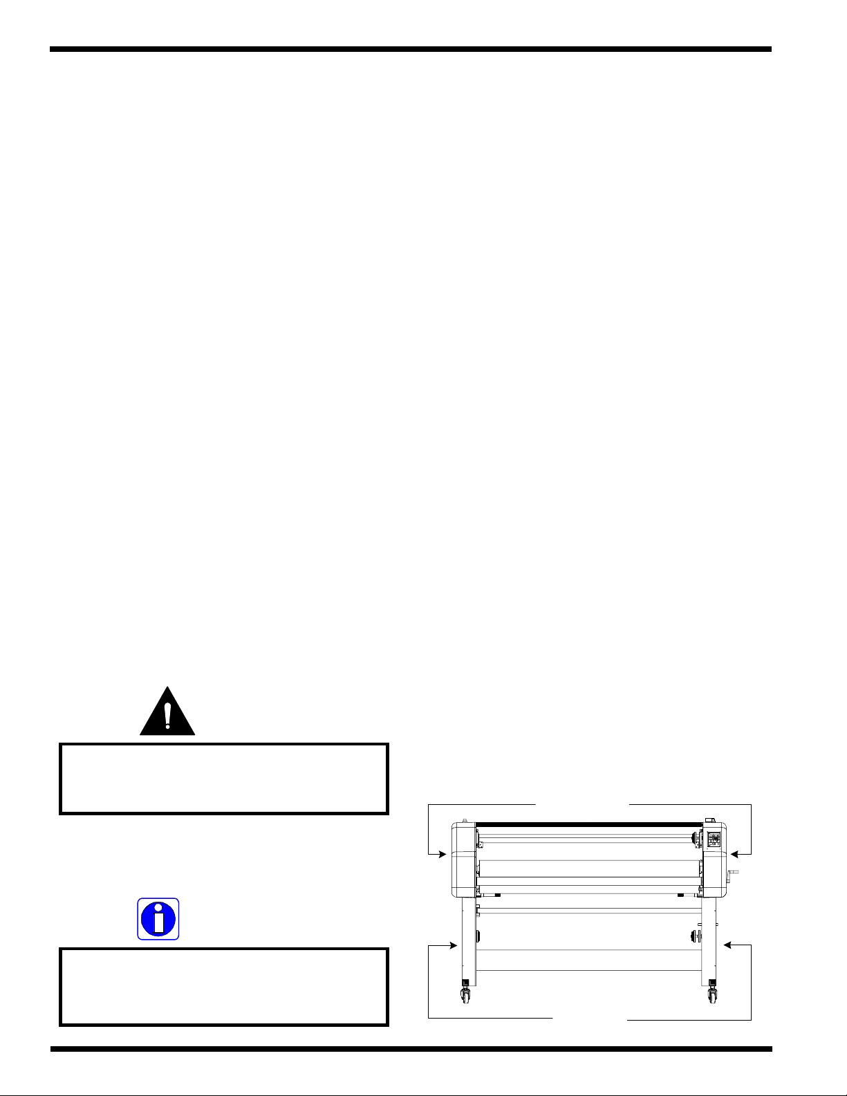
The front and rear tables must be in proper
position for the laminator to operate under normal
condition. Figure 1.2.5 illustrates the tables and keys.
1.3 Installation
The following symbols are positioned at
various points in Section 4 Installation.
CAUTION
Failure to follow the pre-installation check
list can result in damage to the laminator.
If these tables are removed, you may operate
the laminator using the variable speed footswitch. The
speed is controlled through a “accelerator pedal” style
footswitch. Please see footswitch in section 3 of this
manual.
Figure 1.2.5 Tables and keys
WARNING
The operating environment must be free of
dust, flammable liquids and vapors. You can
be injured by inhaling chemical vapors.
WARNING
Vapor build up or stored flammable liquids
can cause a fire. Excessive dust can damage
the laminator.
CAUTION
Do not locate the laminator where air is
blowing directly on the machine. The air
flow can cool the rolls unevenly and result in
poor quality output.
© GBC Pro - Tech August 1999Page 1 - 4
Page 20
F - 160 Operation and Maintenance Manual
Safety
WARNING
Be sure to follow the correct wiring diagram
when supplying power to the laminator. If
improperly connected, you can be seriously
injured or cause damage to the laminator.
INFORMATION
ALL SHIPMENTS ARE EX-WORKS.
dock, title passes to the buyer. Please review
your insurance coverage prior to shipment,
as you are responsible for all subsequent
freight charges and risks.
At our
people. You can be severely injured, crushed
WARNING
The unpacking process requires at least two
or cause damage to the laminator.
CAUTION
Do not use a knife or other sharp object to
remove the shrink wrap from around the
laminator. You can cause irreparable
damage to the rollers.
INFORMATION
Before signing the Bill of Lading, you should
be sure to inspect the crate and / or pallet
for signs of damage or missing items; if
applicable, make note of this on the Bill of
Lading.
INFORMATION
Depending on the destination and customer
preference, the Falcon 160 may be shipped
in various ways. The laminator may arrive
shrink wrapped or in a plywood crate on a
skid. Please follow the unpacking procedure
that pertains to your method of shipment.
Do not attempt to move the laminator across
Do not allow the top to fall into the crate. It
WARNING
anything other than a flat level surface
without trained and qualified riggers. You
can be crushed or seriously injured.
CAUTION
can damage the laminator.
© GBC Pro - Tech August 1999 Page 1 - 5
Page 21
Safety F - 160 Operation and Maintenance Manual
INFORMATION
Do not put packing screws on the floor.
They can cause problems when trying to roll
the laminator into position or you can
become injured if stepped on.
CAUTION
A second person must support the side
labeled 5 in Figure 4.4.1 It can fall and
damage the laminator or cause harm to you
and others.
CAUTION
Do not allow the top to fall into the crate. It
can damage the laminator.
WARNING
Do not attempt to use the ramps if they are
not secured to the pallet. Make sure you
have the pallet on a flat even surface before
attempting to roll the machine off using the
ramps.
WARNING
The Falcon 160 Laminator is a large and
heavy piece of equipment. It is necessary to
employ LICENSED RIGGERS ONLY to
move the laminator. The laminator is not
designed to be tipped up or sideways in any
way. Such action disturbs the exact
alignment of the rolling parts of the machine
and requires extensive realignment. You can
be crushed or seriously injured.
INFORMATION
GBC Pro-Tech's warranty does not cover
malfunction of the equipment due to
mishandling and / or tipping. GBC Pro-
Tech bears no responsibility for personal
injury or damage due to moving the
laminator improperly.
INFORMATION
About recycling: The crate components can
be reused for shipping the laminator again
or can be disassembled and the wood and
screws recycled. The shrink wrap is not
recyclable, so it must be discarded.
INFORMATION
Improper leveling, will result in poor
output quality.
© GBC Pro - Tech August 1999Page 1 - 6
Page 22
F - 160 Operation and Maintenance Manual
Safety
INFORMATION
The side frame provides a more accurate
reading than the cabinet.
servicing the laminator. These items can get
caught in the nip and choke you or you can
INFORMATION
A second person can read the level while you
make the appropriate adjustments.
WARNING
Do not wear ties, loose fitting clothing or
dangling jewelry while operating or
be crushed or burned.
WARNING
If you find a safety feature not working
properly, you should contact your local
service representative immediately
WARNING
Caution should always be exercised
when using the laminator with
the safety shields raised.
You can be seriously HURT or INJURED!
WARNING
Keep hands and fingers clear of the
laminator roller nip when changing GAP.
You can be CRUSHED or BURNED!
INFORMATION
Do not put packing screws on the floor.
They can cause problems when trying to roll
the laminator into position.
INFORMATION
The SAFETY indicator should not be
flashing when the tables are properly
seated and the safety shields are in
the closed position..
© GBC Pro - Tech August 1999 Page 1 - 7
Page 23
Safety F - 160 Operation and Maintenance Manual
INFORMATION
Notice that the footswitch speed is not
indicated in the SPEED DISPLAY on the
front control panel.
1.4 Operations
The following symbols are positioned at
various points in Section 5 Operations.
WARNING
Keep hands and fingers clear of
the laminator roller nip when
adjusting PRESSURE.
You can be CRUSHED or BURNED!
INFORMATION
When the safety shield is in the lowered
position and "Footswitch" mode is engaged,
speed is controlled through the control
panel.
INFORMATION
Read the following warnings and cautions
before attempting to operate or service the
Falcon 160 Laminator.
INFORMATION
When any command is pressed on the
control panel, a "beep" will sound. If the
command is held down, the panel will
"beep" only once.
INFORMATION
If the variable speed footswitch is not
close to the speed of the control panel,
output quality may be affected by the
speed difference.
WARNING
INFORMATION
When adjusting the pressure, the gap
will be affected as well.
When operating the laminator using the
variable speed footswitch, keep hands and
fingers away from the nip of the rollers.
You may be CRUSHED or BURNED!
© GBC Pro - Tech August 1999Page 1 - 8
Page 24
F - 160 Operation and Maintenance Manual
Safety
CAUTION
Speed is controlled through the variable
speed footswitch when the safety shield
is in the raised position.
WARNING
Caution should always be exercised
when using the laminator with
the safety shields raised.
You can be seriously HURT or INJURED!
INFORMATION
Footswitch speed is not indicated in the
SPEED DISPLAY on the control panel.
INFORMATION
When the safety shield is lowered, speed
reverts to the panel speed setting.
WARNING
INFORMATION
When a safety shield is raised while pressing
on the variable speed footswitch, the speed
may be faster or slower than the indicated
panel speed.
INFORMATION
When the safety shield is raised, the
laminator will only run while the variable
speed footswitch is depressed.
At these temperatures there is a danger
ofsevere burn if the rolls are touched
duringsetup, operation or servicing.
INFORMATION
When an EMERGENCY STOP is engaged,
all motion stops. The nip will not change
from the operating setting.
INFORMATION
Twisting the roll of film while sliding
makes loading the film onto the
unwind shaft easier.
© GBC Pro - Tech August 1999 Page 1 - 9
Page 25
Safety F - 160 Operation and Maintenance Manual
INFORMATION
CAUTION
Ensure the roll of laminate is loaded
properly on the unwind shaft.
Exposed adhesive should be facing
away from the rollers.
This will prevent hours of roll cleaning!
INFORMATION
For the lower unwind shaft, add 1/4 in. to
the measurement.
Slow speed will assists with heat up times
and distributes heat evenly.
INFORMATION
When the laminator is first turned on, the
front control panel will go into the default
mode.
Default mode; TOP TEMP. = 68
o
F ( 20 oC ),
BOT. TEMP. = 68 oF ( 20 oC ), GAP = 1 in.,
PRESSURE = no bars are solid, JOB = 0, no
motion direction selected, SPEED = 00.0 and
SLEEP = flashing
INFORMATION
When requiring top and bottom heat, it is
recommended to set both temperatures to
the same set point.
INFORMATION
Do not add PRESSURE when heating the
laminating rollers, this allows the high
release silicone to expand with minimum
restrictions.
WARNING
Keep hands and fingers clear of the
laminator roller nip when changing GAP.
You can be CRUSHED or BURNED!
INFORMATION
When storing parameters within the JOB
SAVE feature of the laminator, PRESSURE
is not a storable setting.
© GBC Pro - Tech August 1999Page 1 - 10
Page 26
F - 160 Operation and Maintenance Manual
Safety
CAUTION
If you accidentally press SAVE at any time,
the old parameters will be replaced with the
new parameters.
INFORMATION
You should store each job location with its
parameters on the chart provided in
Figure 5.4.1
INFORMATION
Density of the substrate will determine the
amount of pressure you may use.
INFORMATION
If the main laminating rollers are heated,
mounting application may be run from the
rear operating position of the machine.
CAUTION
Sharp edges on a substrate should be filed
smooth and GAP manually adjusted.
Sharp edges can CUT the rollers!
CAUTION
Excess pressure can damage the laminating
rollers. Always use the minimum roll
pressure necessary to complete the task.
WARNING
Keep hands and fingers clear of the pull
roller nip when changing the gap.
You can be CRUSHED!
CAUTION
Excess pressure can damage the laminating
rollers. Always use the minimum roll
pressure necessary to complete the task.
INFORMATION
Excessive pressure will cause the
substrate to bow or flatten.
Excessive pressure will cause the
substrate to bow or flatten.
INFORMATION
© GBC Pro - Tech August 1999 Page 1 - 11
Page 27
Safety F - 160 Operation and Maintenance Manual
CAUTION
If not installed properly, you can be injured
or cause damage to the table or laminator.
1.5 Applications
The following symbols are positioned at
various points in Section 6 Applications.
CAUTION
Sharp edges on a substrate should be filed
smooth and GAP manually adjusted.
Sharp edges can CUT the rollers!
WARNING
Caution should always be exercised
when using the laminator with
the safety shields raised.
You can be seriously HURT or INJURED!
WARNING
Do not wear ties, loose fitting clothing or
dangling jewelry while operating or
servicing the laminator. These items can get
caught in the nip and choke you or you can
be crushed or burned.
INFORMATION
The mount adhesive must not exceed 1 in.
the width of the substrate. If it does, you
will experience complications with this
application.
INFORMATION
Twisting the roll of craft paper while
sliding makes loading the film onto
the unwind shaft easier.
CAUTION
Ensure the roll of laminate is loaded
properly on the unwind shaft.
Exposed adhesive should be facing
away from the rollers.
This will prevent hours of roll cleaning!
© GBC Pro - Tech August 1999Page 1 - 12
Page 28
F - 160 Operation and Maintenance Manual
Safety
CAUTION
Ensure the roll of mount adhesive is
loaded properly on the unwind shaft.
Exposed adhesive should be
facing away from the rollers.
This will prevent hours of roll cleaning!
WARNING
Keep hands and fingers clear of the
laminator roller nip when changing GAP.
You can be CRUSHED or BURNED!
WARNING
When operating the laminator using the
variable speed footswitch, keep hands and
fingers away from the nip of the rollers.
You may be CRUSHED or BURNED!
CAUTION
Speed is controlled through the variable
speed footswitch when the safety shield
is in the raised position.
INFORMATION
If the thickness of the substrate is not
known, follow the procedure to manually
set the nip in Section 5.5.1 Manually nip
adjustment.
WARNING
Keep hands and fingers clear of
the laminator roller nip when
adjusting PRESSURE.
You can be CRUSHED or BURNED!
INFORMATION
Excessive pressure will cause the
substrate to bow or flatten.
CAUTION
Excess pressure can damage the laminating
rollers. Always use the minimum roll
pressure necessary to complete the task.
© GBC Pro - Tech August 1999 Page 1 - 13
Page 29
Safety F - 160 Operation and Maintenance Manual
INFORMATION
PRESSURE will vary with the thickness
and width of the laminate you are using.
Adjust as necessary.
INFORMATION
The leading edge is the first part of the
board or image that enters the nip
of the rollers.
INFORMATION
When requiring top and bottom heat, it is
recommended to set both temperatures to
the same set point.
INFORMATION
If the main laminating rollers are heated,
mounting application may be run from the
rear operating position of the machine.
INFORMATION
Position the leader board squarely
onto the mount adhesive.
CAUTION
Prolonged contact can form flat spots on the
rollers.
CAUTION
INFORMATION
Do not add PRESSURE when heating the
laminating rollers, this allows the high
release silicone to expand with minimum
restrictions.
INFORMATION
Slow speed will assists with heat up times
and distributes heat evenly.
When manually setting the main roll nip,
observe the substrate to prevent crushing.
© GBC Pro - Tech August 1999Page 1 - 14
Page 30
F - 160 Operation and Maintenance Manual
Safety
INFORMATION
Avoid tacking at the ends first and pressing
towards the center, you may create a tunnel
once you have reached the center. This will
make for a difficult mounting application.
INFORMATION
If the board is not squarely positioned,
you may experience difficulties with
this application.
WARNING
Keep hands and fingers clear of the pull
roller nip when changing the gap.
You can be CRUSHED!
INFORMATION
Do not lower the pull roller so that the
substrate is crushed when passing through.
This will prevent the boards from bowing.
INFORMATION
If the image is not conformed to the roller,
you may experience difficulties with
this application.
INFORMATION
Use a slow speed. If the tack point enters
the rollers nip, you will not be able to
pull the release liner.
CAUTION
Caution should always be exercised when
using a utility knife near the rollers.
You can put cuts into the rollers!
INFORMATION
Stopping the rollers on the print will leave a
pressure line on the image.
© GBC Pro - Tech August 1999 Page 1 - 15
Page 31

Safety F - 160 Operation and Maintenance Manual
1.6 Troubleshooting
CAUTION
The following symbols are positioned at
various points in Section 7 Troubleshooting.
WARNING
Do not wear ties, loose fitting clothing or
dangling jewelry while operating or
servicing the laminator. These items can get
caught in the nip and choke you or you can
be crushed or burned.
INFORMATION
Prolonged contact can form flat spots on the
rollers.
CAUTION
If silicone adhesive contacts the laminating
rollers, remove it IMMEDIATELY using
80% isopropyl alcohol. It can harden within
an hour and bond to the rollers.
For optimal temperature settings of
various laminates, contact your
supplier or sales representative.
1.7 Maintenance
various points in Section 7 Troubleshooting.
CAUTION
Exercise care when cleaning the laminating
rollers with 80% isopropyl alcohol:
Use only in a well ventilated area
Wear rubber gloves
Use only on cool rolls
CLEANING HEATED ROLLERS CAN
IGNITE THE FUMES!
The following symbols are positioned at
WARNING
Do not wear ties, loose fitting clothing or
dangling jewelry while operating or
servicing the laminator. These items can get
caught in the nip and choke you or you can
be crushed or burned.
© GBC Pro - Tech August 1999Page 1 - 16
Page 32

F - 160 Operation and Maintenance Manual
Safety
INFORMATION
Below is a recommended maintenance
schedule. Before performing any of the steps
listed, read through the procedures first.
Please follow the instructions pertaining to
the step you are performing.
ELECTRICAL
SHOCK
Remove power from the laminator before
servicing. You can be severely shocked,
electrocuted or cause a fire.
Do NOT pick or pull heat activated adhesive
CAUTION
Excessive pressure can destroy the silicone
layer by pressing to hard or scrubbing
too long in one spot.
CAUTION
off the rolls when they are cold. You can
cause irreparable damage to the
laminating rolls.
INFORMATION
If improperly performed, you may
encounter other problems with the output
quality.
WARNING
Caution should always be exercised
when using the laminator with
the safety shields raised.
You can be seriously HURT or INJURED!
INFORMATION
When cleaning the bottom main roller,
switch the motion direction to reverse.
When cleaning the bottom pull roller,
switch the motion direction to forward.
This will prevent anything from
being pulled into the nip.
WARNING
When operating the laminator using the
variable speed footswitch, keep hands and
fingers away from the nip of the rollers.
You may be CRUSHED or BURNED!
© GBC Pro - Tech August 1999 Page 1 - 17
Page 33

Safety F - 160 Operation and Maintenance Manual
CAUTION
Speed is controlled through the variable
speed footswitch when the safety shield
is in the raised position.
CAUTION
Use only isopropyl alcohol or rubber cement
eraser to clean the rollers. Harsh chemicals
like toluene, acetone, or MEK can destroy
the silicone covering of the rolls.
WARNING
Keep hands and fingers clear of
the laminator roller nip when
adjusting PRESSURE.
You can be CRUSHED or BURNED!
ELECTRICAL
SHOCK
Remove power from the laminator before
cleaning. You can be severely shocked,
electrocuted or cause a fire.
CAUTION
Exercise care when cleaning the laminating
rollers with 80% isopropyl alcohol:
Use only in a well ventilated area
Wear rubber gloves
Use only on cool rolls
CLEANING HEATED ROLLERS CAN
IGNITE THE FUMES!
WARNING
ELECTRICAL
SHOCK
Do not use liquid or aerosol cleaners on the
laminator. Do not spill liquid of any kind on
the laminator. You can be severely shocked,
electrocuted or cause a fire. Use only a damp
cloth for cleaning unless other wise
specified.
Keep hands and fingers clear of the
laminator roller nip when changing GAP.
You can be CRUSHED or BURNED!
© GBC Pro - Tech August 1999Page 1 - 18
Page 34

F - 160 Operation and Maintenance Manual
1.8 Label locations
!
WARNING
ACHTUNG
!
Safety
Cautions / Warning Label Locations
Posted at various locations on the Falcon 160
Laminator are important safety labels. Pay careful
attention to these labels at all times! Figure 1.8.1
illustrates the location of each of these labels.
!
WARNING
ACHTUNG
!
MISE EN GARDE
!
MISE EN GARDE
!
Chain Pinch Point: Exercise extreme caution when
working around this area. Moving chains and sprockets
are present.
Read Manual: Read the operations manual before
attempting to operate this machine.
!
WARNING
ACHTUNG
!
MISE EN GARDE
!
Roller Pinch Point: Keep hands and fingers away.
Y ou may be crushed and/ or burned.
Electrical Shock: Live voltage present. Exercise
extreme caution. Y ou may be electrocuted!
Danger V oltage: High voltage wires. Y ou may be
shocked, electrocuted, paralyzed or die!
© GBC Pro - Tech August 1999 Page 1 - 19
Page 35

Safety F - 160 Operation and Maintenance Manual
Figure 1.8.1 Label locations
!
!
WARNING
ACHTUNG
!
MISE EN GARDE
!
WARNING
ACHTUNG
!
MISE EN GARDE
!
Inside cabinet
!
WARNING
ACHTUNG
!
MISE EN GARDE
!
Behind Cover
Behind Cover
!
WARNING
ACHTUNG
!
MISE EN GARDE
!
!
WARNING
ACHTUNG
!
MISE EN GARDE
!
Behind cabinet
!
WARNING
ACHTUNG
!
MISE EN GARDE
!
!
WARNING
ACHTUNG
!
MISE EN GARDE
!
Rear location
© GBC Pro - Tech August 1999Page 1 - 20
Page 36

WarrantyF - 160 Operation and Maintenance Manual
Section 2 Warranty
GBC Pro-T ech warrants the equipment sold is
free from defects in material and workmanship for a
period of one ( 1 ) year parts and 90 days labor
from the date of installation. This warranty is the only
warranty made by GBC Pro-T ech and connot be
modified or amended.
GBC Pro-T ech’ s sole and exclusive liability
and the customer’s sole and exclusive remedy
under this warranty shall be, at GBC Pro-T ech’ s
option, to repair or replace any such defective part
or product. These remedies are only available if
GBC Pro-T ech’ s examination of the product
discloses to GBC Pro-T ech’ s satisfaction that such
defects actually exist and were not caused by
misuse, neglect, attempt to repair , unauthorized
alteration or modification, incorrect line voltage,
fire, accident, flood, or other hazard.
THE WARRANTY MADE HEREIN IS
IN LIEU OF ALL OTHER
WARRANTIES, EXPRESS OR
IMPLIED, INCLUDING ANY
WARRANTY OR
MERCHANTABILITY OR FITNESS
FOR A PARTICULAR PURPOSE. GBC
PRO-TECH WILL NOT BE LIABLE
FOR PROPERTY DAMAGE OR
PERSONAL INJURY ( UNLESS
PRIMARILY CAUSED BY ITS
NEGLIGENCE ), LOSS OF PROFIT OR
OTHER INCIDENTAL OR
CONSEQUENTIAL DAMAGES
ARISING OUT OF THE USE OR
INABILITY TO USE THE
EQUIPMENT.
2.2 Exclusions to the
2.1 Limited Warranty
This warranty specifically does not cover
damage to the laminating rollers caused by knives,
razor blades, other sharp objects, failure caused by
adhesives or improper use of the machine. Warranty
repair or replacement does not extend the warranty
beyond the initial one year period from the date of
delivery .
CAUTION
Warranty
This warranty specifically does not
cover;
1. Damage to the laminating rolls caused by
knives, razor blades, other sharp objects or
failure caused by adhesives.
2. Damage to the machine caused by lifting, tilting
and/or any attempt to position the machine other
than rolling on the installed castors on even
surfaces.
3. Improper use of the machine.
Unauthorized customer alterations will
void this warranty.
© GBC Pro - Tech August 1999 Page 2 - 1
4. Damage due from unqualified person(s) servicing the
machine.
Page 37

Warranty F - 160 Operation and Maintenance Manual
Qualified
• Any engineer that has experience with
electrical and mechanical design of lamination
equipment.The engineers should be fully aware of all
aspects of safety with regards to lamination equipment.
• Any commissioning or service engineer must
be of competent nature, trained and qualified to GBC
Pro-T ech standards to fulfill that job. This person will
have completed and passed the full service training
course from GBC Pro-T ech.
• Any GBC T echnician, GBC Specialist, and /
or GBC Pro-T ech Technician that has been through the
GBC Pro-T ech service training course.
© GBC Pro - Tech August 1999Page 2 - 2
Page 38

F - 160 Operation and Maintenance Manual
Section 3.1 General
Specifications
Description :
Features :
Applications :
• Mid level, wide format color finisher for the sheet fed
ink jet market. The Falcon 160 is a self standing, bi
directional laminator..
• T wo unwinds ( 1 upper, 1 lower )
• T wo rewinds ( 1 upper front, 1 lower center )
• Safety shielded
• Infeed and oufeed tables
• Accelerator footswitch
• Job programmable
• Bi-directional system
• Single sided lamination
• Encapsulation
• Mounting
• Decaling
Section 3.2 Consumables
Film T ypes :
Film Diameters :
Core Size :
Film Widths :
• Pressure sensitive laminates
• Pressure sensitive adhesives
• Low melt laminates
• Thermal laminates
• Thermal adhesives
• Up to a 8” roll diameter ( 20.3 cm )
• 3” core standard ( 7.62 cm )
• 2-1/4” optional ( must have optional core adapters )
( 5.72 cm )
• 64” Pressure sensitive ( 162.6 cm )
• 62” Thermal ( 157.8 cm )
Paper Widths :
Mounting Thickness :
• 62” maximum paper width ( 157.8 cm )
• Up to 1” inch thick ( 2.54 cm ) either direction
© GBC Pro - Tech August 1999 Page 3 - 1
Page 39

Specifications F - 160 Operation and Maintenance Manual
Section 3.3 Function
Speed :
Motor :
Heating Capabilities :
Controls :
Job Save :
Roll Design :
• 0 - 15 ft / min ( 0 - 4.6 m / min )
• 2-1/4 horse power drive motor
• Bi-directional D.C. motor
• 68oF - 290oF ( 20oC - 143oC )
• Front control panel
• V ariable speed footswitch
• Save up to 9 job parameters
• High release silicone rolls
Section 3.4 Electrical
United States :
Europe :
B.T .U. output :
Heater W attages :
Amperage Draw :
D/C V oltage used :
Requirements
• 230 - 240 VAC, 50/60 Hz, single phase, 55 amps.
• 230 - 240 VAC, W ye 3 phase, 32 amps/ phase
• 31,732 B.T .U. / hour
• 4650 watts per heater
• No heat, motor only : 1 - 3 amps
• T op heat and motor : 20 - 23 amps
• Both heat and motor : 40 - 43 amps
• 24 vdc
• 12 vdc isolated x 2
• 24 vdc isolated
A/C V oltage used:
• 230 vac ( minimum )
© GBC Pro - Tech August 1999Page 3 - 2
Page 40

F - 160 Operation and Maintenance Manual
Section 3.5 Dimensions
Specifications
W eight :
Dimensions :
Nip Height :
Safety Shield Raised Height :
Figure 3.5.1 Dimensions
• Crated : 1568 lbs. ( 711 kg. )
• Uncrated : 1200 lbs. ( 544 kg. )
• Crated : 90 in. (H) x 46 in. (W) x 72 in. (L)
( 229 cm (H) x 117 cm (W) x 183 cm (L) )
• Uncrated : 54 in. (H) x 38 in. (W) x 82.5 in. (L)
( 137 cm (H) x 96 cm (W) x 209 cm (L) )
Refer to Figure 3.5.1
• 37 3/16 in. ( 95 cm )
• 66 5/8 in. ( 169 cm)
54"
82.5"
Plane4
Plane4
Plane4
38"
© GBC Pro - Tech August 1999 Page 3 - 3
Page 41

Specifications F - 160 Operation and Maintenance Manual
This page intentionally left blank.
© GBC Pro - Tech August 1999Page 3 - 4
Page 42

F - 160 Operation and Maintenance Manual
Installation
Section 4 Installation
GBC Pro-T ech is committed to a program of
ongoing product improvement. As a result, we are
providing these instructions so that you can insure that
your new Falcon 160 Laminator is properly and
securely unpacked, moved, and installed.
Before a Falcon 160 Laminator can be
installed, there are a few requirements that must be
met. Make certain that each of the requirements
listed in the following pre-installation checklist are met
before beginning installation.
Is the environment appropriate for the
laminator? The laminator requires a clean, dust
and vapor free environment to operate
properly. It must not be located where there is
air blowing directly on the machine.
Have you contacted a certified electrician to
both wire the laminator and ensure that
adequate power is being supplied, having the
appropriate capacity, over current protection
and safety lockouts are available.
WARNING
CAUTION
Failure to follow the pre-installation check
list can result in damage to the laminator.
4.1 Pre-installation
Are doorways and hallways wide eneough for
the laminator to be moved to the installation
site?
Is there ample room for the laminator?
The operating environment must be free of
dust, flammable liquids and vapors. You can
be injured by inhaling chemical vapors.
WARNING
Vapor build up or stored flammable liquids
can cause a fire. Excessive dust can damage
the laminator.
CAUTION
A work area must be established that allows
for operation in both the front and rear of the
laminator and provides space for efficient
material flow.
machine area layout.
Figure 4.1.1
illustrates a typical
Do not locate the laminator where air is
blowing directly on the machine. The air
flow can cool the rolls unevenly and result in
poor quality output.
© GBC Pro - Tech August 1999 Page 4 - 1
Page 43

Installation
The laminator requires 230 to 240 vac, 50/60
Hz, 55 amps. Or, in Europe only, 3-N phase,
220 vac, 32 amps per phase.
WARNING
Be sure to follow the correct wiring diagram
when supplying power to the laminator. If
improperly connected, you can be seriously
injured or cause damage to the laminator.
F - 160 Operation and Maintenance Manual
Figure 4.1.2 illustrates proper wiring for single phase
for the U.S..
Figure 4.1.3 illustrates proper wiring for W ye 3 phase
for Europe.
WARNING
The Falcon 160 Laminator is a large and
heavy piece of equipment. It is necessary to
employ LICENSED RIGGERS ONLY to
move the laminator. The laminator is not
designed to be tipped up or sideways in any
way. Such action disturbs the exact
alignment of the rolling parts of the machine
and requires extensive realignment. You can
be crushed or seriously injured.
© GBC Pro - Tech August 1999Page 4 - 2
Page 44

F - 160 Operation and Maintenance Manual
Figure 4.1.1 Suggested Floor Layout
4' x 6' ( 1.22 m x 2m )
Work table on wheels
8.4'
( 2.57 m )
Table height
35-3/4" ( .94 - .95m )
Installation
82.5"
( 209 cm )
20'
( 6 m )
38"
( 96 cm )
8.4'
( 2.57m )
3' ( 1 m)
4' x 6' ( 1.22 m x 2m )
Work table on wheels
Table height
35-3/4" ( .94 - .95m )
13' ( 4 m)
© GBC Pro - Tech August 1999 Page 4 - 3
Page 45

Installation
Figure 4.1. 2 Single phase, U.S.
TB 1
F - 160 Operation and Maintenance Manual
TB 2
G
L1
L2
Incoming line voltage
Figure 4.1.3 Wye 3 phase, Europe only
TB 1
TB 2
G
N
L1
L2
L3
Incoming line voltage
N 2
L 3 - 2
Correct Configuration
© GBC Pro - Tech August 1999Page 4 - 4
Page 46

F - 160 Operation and Maintenance Manual
Installation
4.2 Unpacking
INFORMATION
ALL SHIPMENTS ARE EX-WORKS.
dock, title passes to the buyer. Please review
your insurance coverage prior to shipment,
as you are responsible for all subsequent
freight charges and risks.
INFORMATION
Before signing the Bill of Lading, you should
be sure to inspect the crate and / or pallet
for signs of damage or missing items; if
applicable, make note of this on the Bill of
Lading.
At our
With regards to your shipping methods, use one
of the following procedure described to safely and
properly unwrap / uncrate your laminator .
4.3 Shrink Wrapped
a) Inspect the machine for any obvious shipping
damages upon receipt.
b) Carefully unwrap the shrink wrap from around
the laminator .
CAUTION
INFORMATION
Depending on the destination and customer
preference, the Falcon 160 may be shipped
in various ways. The laminator may arrive
shrink wrapped or in a plywood crate on a
skid. Please follow the unpacking procedure
that pertains to your method of shipment.
WARNING
The unpacking process requires at least two
people. You can be severely injured, crushed
or cause damage to the laminator.
Do not attempt to move the laminator across
Do not use a knife or other sharp object to
remove the shrink wrap from around the
laminator. You can cause irreparable
damage to the rollers.
c) With another person, carefully wheel your
F - 160 Laminator to the installation site.
WARNING
anything other than a flat level surface
without trained and qualified riggers. You
can be crushed or seriously injured.
© GBC Pro - Tech August 1999 Page 4 - 5
Page 47

Installation
F - 160 Operation and Maintenance Manual
4.4 Crated
Tools required
• # 2 Phillips head screwdriver
• 7/8” open end wrench or adjustable wrench
• Crow bar
• A second person
To uncrate the laminator
a) Remove the top of the crate and then the sides
in the order shown in Figure 4.4.1
Figure 4.4.1 Disassembling of the crate
1
P
l
a
n
e
3
4
P
l
a
n
e
4
P
l
a
n
e
4
4
2
5
CAUTION
Do not allow the top to fall into the crate. It
can damage the laminator.
Removing the shrink wrap
INFORMATION
Do not put packing screws on the floor.
They can cause problems when trying to roll
the laminator into position or you can
become injured if stepped on.
CAUTION
A second person must support the side
labeled 5 in Figure 4.4.1 It can fall and
damage the laminator or cause harm to you
and others.
a) Gently unwrap the shrink wrap from around the
laminator.
CAUTION
Do not use a knife or other sharp object to
remove the shrink wrap from around the
laminator. You can cause irreparable
damage to the rollers.
© GBC Pro - Tech August 1999Page 4 - 6
Page 48

F - 160 Operation and Maintenance Manual
Moving the laminator
a) Have the laminator rolled off the skid and
placed on the floor by licensed riggers. The
ramps included with the laminator can be
secured utilizing screws removed from the
disassembled crate. Figure 4.4.2 illustrates
positioning of the ramps.
WARNING
Do not attempt to move the laminator across
anything other than a flat level surface
without trained and qualified riggers. You
can be crushed or seriously injured.
Installation
WARNING
The Falcon 160 Laminator is a large and
heavy piece of equipment. It is necessary to
employ LICENSED RIGGERS ONLY to
move the laminator. The laminator is not
designed to be tipped up or sideways in any
way. Such action disturbs the exact
alignment of the rolling parts of the machine
and requires extensive realignment. You can
be crushed or seriously injured.
INFORMATION
Figure 4.4.2 Positioning of the ramps
WARNING
GBC Pro-Tech's warranty does not cover
malfunction of the equipment due to
mishandling and / or tipping. GBC Pro-
Tech bears no responsibility for personal
injury or damage due to moving the
laminator improperly.
b) Remove any plastic strapping and/or packing
paper taped to the rolls.
CAUTION
Do not attempt to use the ramps if they are
not secured to the pallet. Make sure you
have the pallet on a flat even surface before
attempting to roll the machine off using the
ramps.
Do not use a knife or other sharp object to
remove the shrink wrap from around the
laminator. You can cause irreparable
damage to the rollers.
© GBC Pro - Tech August 1999 Page 4 - 7
Page 49

Installation
F - 160 Operation and Maintenance Manual
c) Remove all packing materials to a safe distance
from the laminator and dispose of properly .
d) Use two people to carefully roll the laminator to
the desired location.
contact your local service technician or sales
representative.
4.6 Leveling
INFORMATION
About recycling: The crate components can
be reused for shipping the laminator again
or can be disassembled and the wood and
screws recycled. The shrink wrap is not
recyclable, so it must be discarded.
way the machine performs. Leveling is crucial to the
tram ( tracking ) of the materials through the machine.
If you are missing any of the itemslisted above,
Leveling of the laminator is very important in the
4.5 Accessory pack
Once the Falcon 160 Laminator has been
unpacked and moved into final position, open the
accessory pack and verify the contents.
Accessory Pack contents
• One T-handle allen wrench ( 475-200 )
• One Zippy knife ( 475-620 )
• One T erry clothe towel ( 475-950 )
• One Operators manual ( 930-031 )
• One roll masking tape ( 475-000 )
• T wo Polyurethane O-rings ( 480-005 )
• One strain relief for main power ( 175-201 )
• One rubber cement pad ( 930320 )
• One crankhandle ( 629-018 )
• One fuse, 0.5A ( 186-022 )
• T wo fuses, 2.5A ( 186-220 )
INFORMATION
Improper leveling, will result in poor
output quality.
Tools required
• T orpedo level
• ( 2 ) 3/4” open end wrenches
• Four leveling pads
( from the accessory pack )
• Second person
Preparation
a) V erify that the laminator has sufficient room
around it to load film, walk around and
serviced if necessary .
© GBC Pro - Tech August 1999Page 4 - 8
Page 50

F - 160 Operation and Maintenance Manual
g
Installation
b) Attach one leveling pad to each one of the four
foot bolts near the castors. Refer to Figure
4.6.1
Figure 4.6.1 Foot bolts
Foot bolts
b) Level the control side from front to back.
INFORMATION
A second person can read the level while you
make the appropriate adjustments.
c) Position the level on the top of the drive side
frame. Not on the cabinet.
d) Level the drive side from front to back.
Levelin
s
t
pads
c) Lock the castors in place to prevent the
laminator from rolling while leveling.
Leveling
a) Position the level on the top of the control side
frame. Not on the cabinet. Refer to Figure
4.6.2
Figure 4.6.2 Front to back
Level
INFORMATION
The side frame provides a more accurate
reading than the cabinet.
© GBC Pro - Tech August 1999 Page 4 - 9
Page 51
Installation
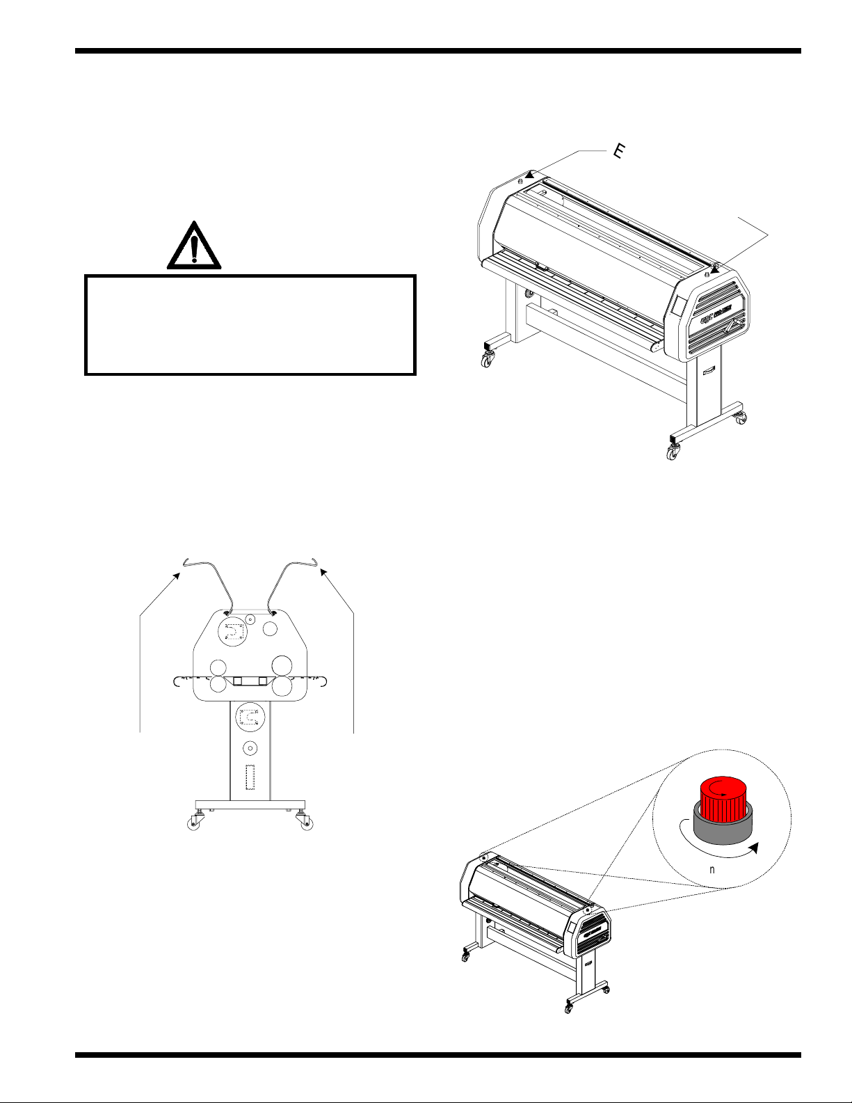
e) Ensure that nothing is in the path of the main roll
nip.
f) Confirm that power is supplied to the laminator.
F - 160 Operation and Maintenance Manual
WARNING
Caution should always be exercised
when using the laminator with
the safety shields raised.
You can be seriously HURT or INJURED!
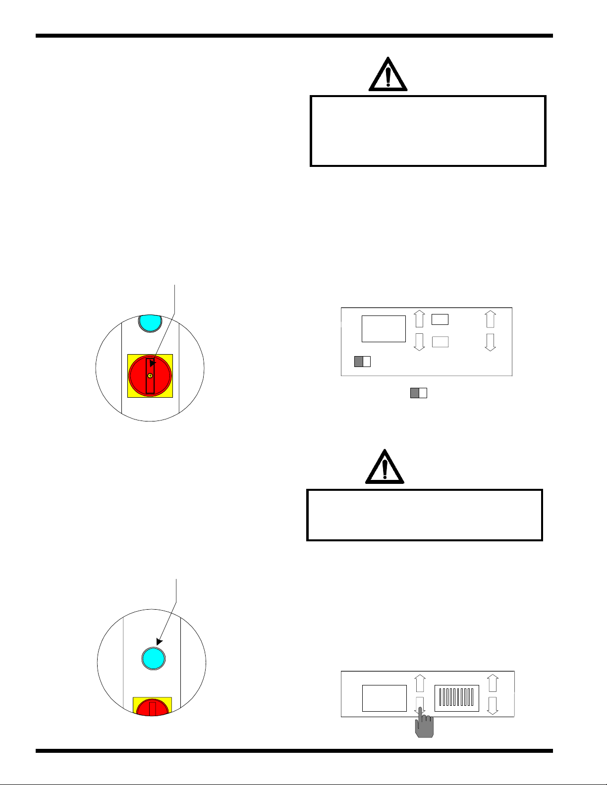
g) Turn the MAIN POWER to “ON” position.
Main Power
h) Press RESET. The front control panel should
be illuminated at this point.
i) Raise the front safety shield. The SAFETY
indicator will begin flashing.
FWR
REV.
00.0
SPEED
SAFETY
GO
STOP
= Flashing
WARNING
Keep hands and fingers clear of the
laminator roller nip when changing GAP.
You can be CRUSHED or BURNED!
Reset
j) Press GAP t to “0”.
GAP PRESSURE
0
© GBC Pro - Tech August 1999Page 4 - 10
Page 52

F - 160 Operation and Maintenance Manual
Installation
k) Place the level across the top of the upper main
roll in the center . Refer to Figure 4.6.4
Figure 4.6.4 Left to right
Level
Plane4
o) Remove the level.
p) Lower the front safety shield.
q) Turn MAIN POWER to “OFF “.
Plane4
4.7 Safety check
l) Level the machine from left to right.
m) V erify your adjustments when finished.
n) Press GAP
ss
s to 1 in. setting.
ss
The safety check will ensure that all safety
devices and interlock switches are functioning properly .
WARNING
Do not wear ties, loose fitting clothing or
dangling jewelry while operating or
servicing the laminator. These items can get
caught in the nip and choke you or you can
be crushed or burned.
WARNING
GAP
1
PRESSURE
properly, you should contact your local
service representative immediately
© GBC Pro - Tech August 1999 Page 4 - 11
If you find a safety feature not working
Page 53

Installation
F - 160 Operation and Maintenance Manual
4.7.1 Front and rear infeed
tables
a) Turn MAIN POWER to “ON” .
Main power
d) Press FWD s to set a forward motor
direction.
FWR
REV.
00.0
SPEED
SAFETY
GO
STOP
e) Press SPEED s to set a speed of 6 ft/min.
b) Press RESET. The front control panel will be
illuminated.
Reset
c) Press SEL. The SEL key should stop flashing.
FWR
REV.
6.0
SPEED
SAFETY
GO
STOP
f) Press GO. The bottom rollers will begin to turn.
JOB
0
SEL
SHUT DOWN
SAV
6.0
SPEED
SAFETY
© GBC Pro - Tech August 1999Page 4 - 12
GO
FWR
REV.
STOP
Page 54
F - 160 Operation and Maintenance Manual
Installation
g) Slightly lift the front infeed table. SAFETY
indicator and GO begin flashing and the
bottom rollers stop.
FWR
REV.
6.0
SPEED
SAFETY
GO
STOP
= Flashing
h) Lower the front infeed table.SAFETY
indicator reverts to white and GO remains
flashing.
j) Press GO. The bottom rollers begin turning.
FWR
REV.
6.0
SPEED
SAFETY
GO
STOP
k) Slighly lift the rear infeed table. SAFETY
indicator and GO begin flashing and the bottom
rollers stop.
FWR
REV.
6.0
SPEED
SAFETY
GO
STOP
= Flashing
i) Press STOP. GO stops flashing.
FWR
REV.
6.0
SPEED
SAFETY
GO
STOP
FWR
REV.
6.0
SPEED
SAFETY
GO
STOP
= Flashing
l) Lower the rear infeed table. SAFETY indicator
reverts to white and GO remains flashing.
FWR
REV.
6.0
SPEED
SAFETY
GO
STOP
= Flashing
© GBC Pro - Tech August 1999 Page 4 - 13
Page 55

Installation
F - 160 Operation and Maintenance Manual
m) Press STOP. GO stops flashing.
FWR
REV.
6.0
SPEED
SAFETY
GO
STOP
4.7.2 Front and rear safety
shields
b) Raise the front safety shield. SAFETY indicator
and GO begin flashing and the bottom rollers
stop.
FWR
REV.
6.0
SPEED
SAFETY
GO
STOP
= Flashing
h) Lower the front safety shield. SAFETY
indicator reverts to white and GO remains
flashing.
a) Press GO. The bottom rollers begin turning.
FWR
REV.
6.0
SPEED
SAFETY
GO
STOP
WARNING
Caution should always be exercised
when using the laminator with
the safety shields raised.
You can be seriously HURT or INJURED!
FWR
REV.
6.0
SPEED
SAFETY
GO
STOP
= Flashing
i) Press STOP .GO stops flashing.
FWR
REV.
6.0
SPEED
SAFETY
GO
STOP
© GBC Pro - Tech August 1999Page 4 - 14
Page 56

F - 160 Operation and Maintenance Manual
Installation
j) Press GO. The bottom rollers begin turning.
FWR
REV.
6.0
SPEED
SAFETY
GO
STOP
WARNING
Caution should always be exercised
when using the laminator with
the safety shields raised.
You can be seriously HURT or INJURED!
l) Lower the rear safety shield. SAFETY indicator
reverts to white and GO remains flashing.
FWR
REV.
6.0
SPEED
SAFETY
GO
STOP
= Flashing
m) Press STOP. GO stops flashing.
FWR
REV.
6.0
SPEED
SAFETY
GO
STOP
k) Raise the rear safety shield. SAFETY indicator
and GO begin flashing and the bottom rollers
stop.
FWR
REV.
6.0
SPEED
SAFETY
GO
STOP
= Flashing
4.7.3 EMERGENCY STOPS
( E-STOP )
a) Press GO. The bottom rollers begin turning.
FWR
REV.
6.0
SPEED
SAFETY
GO
STOP
© GBC Pro - Tech August 1999 Page 4 - 15
Page 57

Installation
Push
Unl
h
F - 160 Operation and Maintenance Manual
b) Press down on the control side E-STOP. The
E-STOP latches in the down position, bottom
rollers stop, and the control panel is blank
c) Unlatch the E-STOP as illustrated below .
e) Press SEL. SEL stops flashing.
JOB
SEL
0
SHUT DOWN
SAV
f) Press FWD s for a forward motor direction.
atc
d) Press RESET. The front control panel is
illuminated.
RESET
FWR
REV.
00.0
SPEED
SAFETY
GO
STOP
g) Press SPEED s to a speed of 6 ft/min.
FWR
REV.
6.0
SPEED
SAFETY
GO
STOP
© GBC Pro - Tech August 1999Page 4 - 16
Page 58
F - 160 Operation and Maintenance Manual
Push
Unl
h
Installation
h) Press GO. The bottom rollers will begin to
turn.
6.0
SPEED
SAFETY
i) Press down on the drive side E-STOP. The E-
STOP latches in the down position, bottom
rollers stop, and the control panel is blank.
GO
STOP
FWR
REV.
k) Press RESET. The front control panel is
illuminated.
RESET
4.8 Function check
j) Unlatch the E-STOP as illustrated below .
atc
The function check ensures that the laminator
functions properly when operating. This check is
recommended before performing any applications.
If you find a step that does not react according
to the description, call your local area service
representative immediately .
WARNING
Do not wear ties, loose fitting clothing or
dangling jewelry while operating or
servicing the laminator. These items can get
caught in the nip and choke you or you can
be crushed or burned.
© GBC Pro - Tech August 1999 Page 4 - 17
Page 59

Installation
F - 160 Operation and Maintenance Manual
4.8.1 Control panel
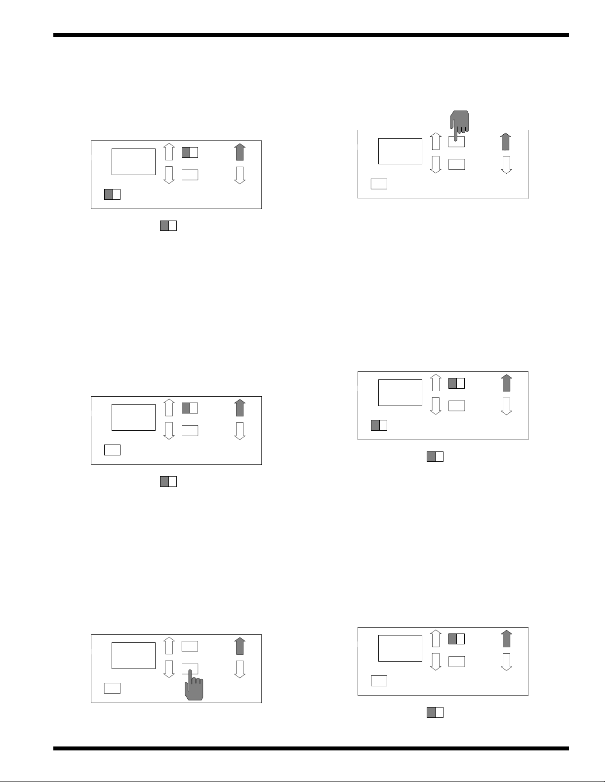
a) Press TOP TEMP . s to a value of 120oF
( 48 oC ). TOP TEMP DISPLAY begins
flashing.
SLEEP
TOP TEMP.
120
b) Press BOT TEMP s to a value of 120oF
( 48 oC ). BOT TEMP DISPLAY begins
flashing.
BOT. TEMP
68
d) Press GAP s. GAP DISPLAY increases
1/16th of an inch per press. The upper main roll
moves accordingly . Once to “1”, the upper
main roller stops.
GAP
PRESSURE
0 - 1
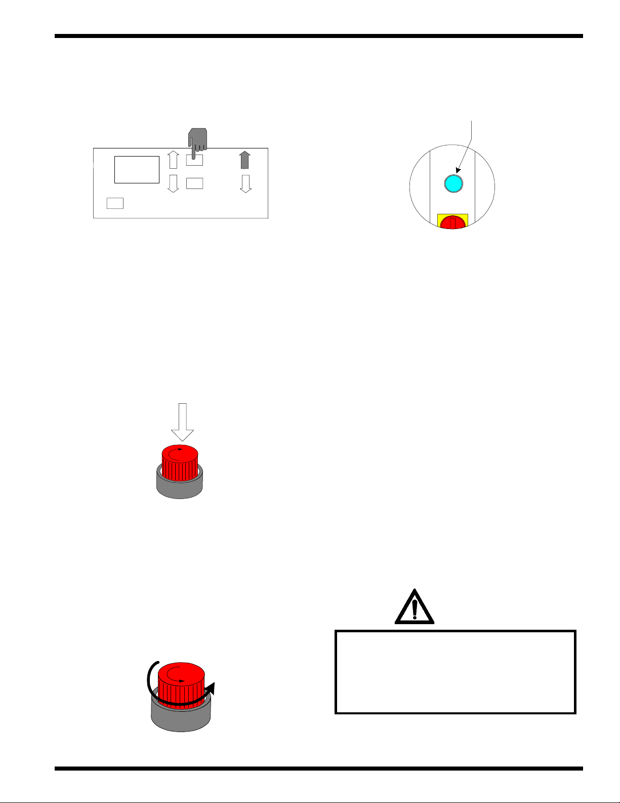
e) Press and hold PRESSURE t. The upper
main roller travels in a constant downward
motion. Once making contact with the lower
main roller, the bars turn solid one at a time until
all 10 bars are solid.
SLEEP
TOP TEMP.
120
c) Press GAP t once. GAP DISPLAY
decreases 1/16th of an inch per press. The
upper main roller moves accordingly . Once to
“0”, the upper main roller is contacting the
lower main roller.
GAP PRESSURE
BOT. TEMP
120
1 - 0
GAP PRESSURE
0
f) Press and hold PRESSURE s. The upper main
roller travels in a constant upward motion. The
pressure bars turn hollow one at a time until no
bars are solid and GAP DISPLAY changes to
“1” then stops.
GAP PRESSURE
1
© GBC Pro - Tech August 1999Page 4 - 18
Page 60

F - 160 Operation and Maintenance Manual
g) Press JOB s. The JOB DISPLAY should
increases in increments of 1 to 9.
Installation
INFORMATION
To continue with the function checks, you
must press SEL so that it discontinues
flashing.
JOB
SEL
9
SHUT DOWN
SAV
h) Press JOB t . The JOB DISPLAY should
decreases in increments of 1 from 9 to 0.
JOB
SEL
0
SHUT DOWN
SAV
j) Press SPEED s once. SPEED DISPLAY
increases in increments of .5 per press up to 15.
FWR
REV.
15
SPEED
SAFETY
GO
STOP
k) Press FWD s. FWD is solid.
i) SEL can not be tested until you have saved
parameters within a JOB location. Refer to
Section 5.4 Job programming for SEL and
SAV.
FWR
REV.
JOB
0
SEL
SHUT DOWN
= Flashing
SAV
15
SPEED
SAFETY
GO
STOP
© GBC Pro - Tech August 1999 Page 4 - 19
Page 61

Installation
F - 160 Operation and Maintenance Manual
l) Press GO. The bottom rollers turn in a forward
motion at a speed of 15 ft./min.
( 4.57 m / min. ).
FWR
REV.
15
SPEED
SAFETY
GO
STOP
m) Press STOP. The bottom rollers stop turning.
o) Press GO. The bottom rollers turn in a reverse
motion at a speed of 15 ft./min.
( 4.57 m / min. ).
FWR
REV.
15
SPEED
SAFETY
GO
STOP
p) Press STOP. The bottom rollers stop turning.
FWR
REV.
15
SPEED
SAFETY
GO
STOP
n) Press REV t . REV is solid and FWD
reverts to hollow .
FWR
REV.
15
SPEED
SAFETY
GO
STOP
FWR
REV.
15
SPEED
SAFETY
GO
STOP
q) Press SPEED t once. SPEED DISPLAY
decreases in increments of .5 per press down to
00.0.
FWR
REV.
00.0
SPEED
SAFETY
GO
STOP
© GBC Pro - Tech August 1999Page 4 - 20
Page 62

F - 160 Operation and Maintenance Manual
Installation
r) The TOP TEMP DISPLA Y and BOT TEMP
DISPLA Y are solid indicating the actual
temperature is within a +/- 10oF of the set point
temperature.
SLEEP
TOP TEMP.
120
BOT. TEMP
120
Figure 4.8.1 Default settings
WARNING
Caution should always be exercised
when using the laminator with
the safety shields raised.
You can be seriously HURT or INJURED!
u) Press SHUTDOWN. The laminator reverts to
the default settings and SLEEP is solid. Refer
to Figure 4.8.1
JOB
0
SLEEP
SEL
SHUT DOWN
SAV
s) Raise the front safety shield, remove the front
infeed table and touch the two main rollers.
They should feel warm to the touch.
t) Replace the front infeed table and lower the
front safety shield.
INFORMATION
TOP TEMP
68
GAP
1
0
00.0
SPEED
SAFETY
BOT TEMP
68
PRESSURE
SEL
SHUT DOWN
FWD
GO
REV
STOP
SAV
The SAFETY indicator should not be
flashing when the tables are properly
seated and the safety shields are in
the closed position..
= Flashing
© GBC Pro - Tech August 1999 Page 4 - 21
Page 63
Installation
g
F - 160 Operation and Maintenance Manual
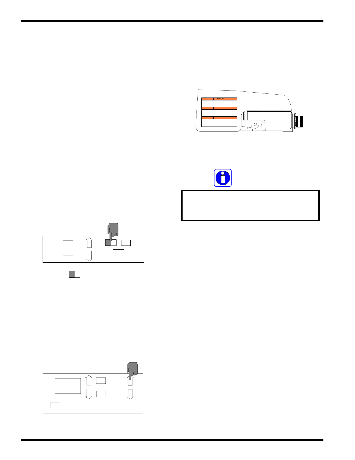
4.8.2 Variable speed
footswitch
This check is to ensure that the footswitch
works. For complete instructions on the footswitch and
its relation to “Footswitch” mode to “ Panel” mode,
refer to Section 5.1 Controls / ( 28 ) Footswitch.
a) Press SEL on the front control panel to “wake”
the laminator from SLEEP mode. SLEEP
indicator reverts to hollow .
c) Press down on the variable speed footswitch.
GO begins flashing and the bottom rollers are
turning.
ATTUNG
WARNING
ADVERTENCIA
INFORMATION
Notice that the footswitch speed is not
indicated in the SPEED DISPLAY on the
front control panel.
JOB
SEL
0
SHUT DOWN
=
Flashin
SAV
b) Press FWD s for a forward motor direction.
FWD is solid.
FWR
REV.
00.0
SPEED
SAFETY
GO
STOP
4.8.3 Unwind shafts and
unwind brakes
The unwind shafts swing out and the unwind
brakes tension the turning of the shaft from no tension to
complete stop tension.
Should you detect or experience complications
with the unwind shaft movement or the unwind brake
tension, call you local area service representative.
© GBC Pro - Tech August 1999Page 4 - 22
Page 64

F - 160 Operation and Maintenance Manual
Installation
WARNING
Caution should always be exercised
when using the laminator with
the safety shields raised.
You can be seriously HURT or INJURED!
a) Raise the rear safety shield.
b) Lift the clevis pin up from the saddle of the
upper unwind shaft.
INFORMATION
Steps " e" and " f" will be performed
simultaneously.
e) W ith one hand, slowly turn the upper unwind
shaft in either direction.
f) With the other hand, slowly turn the upper
unwind brake adjustment knob clockwise.
Saddle
Clevis pin
c) Swing the upper unwind shaft to its fully
extended position. Swing back and reseat the
shaft in the saddle. The swing movement should
be smooth and easy .
d) Ensure that the upper unwind brake adjustment
knob is backed off completly . The counter
clockwise turn should be easy .
Upper unwind brake
adjustment knob
g) You should feel an increase in resistance on the
turning of the upper unwind shaft as you turn the
upper unwind brake adjustment knob
clockwise.
© GBC Pro - Tech August 1999 Page 4 - 23
Page 65

Installation
h) Slowly turn the upper unwind brake adjustment
knob counter clockwise.
i) Y ou should feel a decrease in resistance on the
turning of the upper unwind shaft as you turn the
upper unwind brake adjustment knob counter
clockwise.
j) Lower the rear safety shield.
F - 160 Operation and Maintenance Manual
k) Now perform steps “b” through “h” again for
the lower unwind shaft.
Lower unwind
brake adjustment dial
© GBC Pro - Tech August 1999Page 4 - 24
Page 66

F - 160 Operation and Maintenance Manual
Operations
Section 5 Operations
The operator control panel for the Falcon 160
Laminator is located on the front of the machine, to the
right of the front operating position.
For an illustration of the complete front control
panel, please refer to Figure 5.1.1. The names and
functions of these controls are as follows:
INFORMATION
When any command is pressed on the
control panel, a "beep" will sound. If the
command is held down, the panel will
"beep" only once.
( 2 ) TOP TEMP DISPLA Y : The display will show
the set point temperature of the top main roller as the
default display . When the top roller temperature has
reached in the +/- 10oF range of the set point, the
display will be solid. When outside of this range, the
display will flash.
SLEEP
TOP TEMP.
32
2
( 3 ) TOP TEMP s : When pressed, will increase the
set point value of the top main roller in increments of 2
degrees. If held down, it will only increase to the
maximum temperature setting of 290oF ( 143oC ).
BOT. TEMP
32
3
5.1 Control Panel
( 1 ) SLEEP: If flashing, the machine is in sleep mode.
This will occur after 3 hours of no activity . T o wake the
laminator from sleep mode, press any command.
1
SLEEP
TOP TEMP.
32
BOT. TEMP
32
SLEEP
TOP TEMP.
32
( 4 ) TOP TEMP t : When pressed, will decrease the
set point value of the top main roller in increments of 2
degrees. If held down, it will only decrease to the
minimum temperature setting of 68oF ( 20oC ).
SLEEP
TOP TEMP.
32
BOT. TEMP
32
BOT. TEMP
32
4
© GBC Pro - Tech August 1999 Page 5 - 1
Page 67

Operations
F - 160 Operation and Maintenance Manual
( 5 ) BOT . TEMP . DISPLA Y : The display will show
the set point temperature of the bottom main roller as
the default display . When the bottom roller temperature
has reached in the +/- 10oF range of the set point, the
display will be solid. When outside of this range, the
display will flash.
SLEEP
TOP TEMP.
32
BOT. TEMP
32
5
( 6 ) BOT . TEMP . s : When pressed, will increase
the set point value of the bottom main roller in
increments of 2 degrees. If this key is held down, it will
only increase to the maximum temperature setting of
290oF ( 143oC ).
( 8 ) GAP DISPLA Y : Displays the current main roller
nip opening. The nip has a range of 0 to 1” gap.
GAP
PRESSURE
1/4
8
( 9 ) GAP s : When pressed, will increase the gap by
1/16 in. increments. If held down, it will automatically
increase the gap by 1/16 in. increments until it has
reached a maximum opening of 1 in. on the GAP
DISPLA Y.
6
SLEEP
TOP TEMP.
68
BOT. TEMP
68
( 7 ) BOT . TEMP . t : When pressed, will decrease
the set point value of the bottom main roller in
increments of 2 degrees. If held down, it will decrease
to the minimum temperature setting of 68oF ( 20oC ).
SLEEP
TOP TEMP.
BOT. TEMP
9
GAP
PRESSURE
1/4
( 10 ) GAP t : When pressed, will decrease the gap
by 1/16 in. increments. If held down, it will
automatically decrease the gap by 1/16 in. increments
until it has reached a minimum opening of 0 in. on the
GAP DISPLA Y.
GAP
PRESSURE
1/4
68
68
10
7
© GBC Pro - Tech August 1999Page 5 - 2
Page 68

F - 160 Operation and Maintenance Manual
Operations
( 1 1 ) PRESSURE DISPLA Y : Displays the amount
of pressure being used. Each bar represents 10% of the
maximum allowable pressure. All ten bars illuminated
equals 100% of the maximum allowable pressure.
GAP PRESSURE
1/4
11
INFORMATION
When adjusting the pressure, the gap
will be affected as well.
( 13 ) PRESSURE t : When pressed once, will
increase the pressure by 5%. If held down, it will
increase from 0% of the minimum allowed pressure to
100% at which point all bars will be illuminated.
GAP PRESSURE
1/4
13
( 14 ) JOB DISPLA Y : Displays the job number
selected and will set the operating parameters saved for
that number once SEL has been pressed.
( 12 ) PRESSURE s : When pressed once, will
decrease the pressure by 5%. If held down, it will
decrease from 100% of the maximum allowed pressure
to 0% at which point no bars will be illuminated.
12
GAP
PRESSURE
1/4
WARNING
Keep hands and fingers clear of
the laminator roller nip when
adjusting PRESSURE.
You can be CRUSHED or BURNED!
14
JOB
SEL
5
SHUT DOWN
SAV
INFORMATION
Job programming is explained in
Section 5.4
© GBC Pro - Tech August 1999 Page 5 - 3
Page 69

Operations
F - 160 Operation and Maintenance Manual
( 15 ) JOB s : When pressed once will increase the
job number in JOB DISPLA Y by increments of 1. If
pressed and held, the JOB DISPLA Y will increase to
9 at which point it will stop.
15
JOB
SEL
5
SHUT DOWN
SAV
( 16 ) JOB t : When pressed once will decrease the
job number in JOB DISPLA Y by increments of 1. If
pressed and held, the JOB DISPLA Y will decrease to
0 at which point it will stop.
( 18 ) SAVE : When pressed, will save the current
settings for the number showing in the JOB DISPLA Y.
For more information, refer to Section 5.4 Job
Programming on how to save parameters.
18
JOB
SEL
5
SHUT DOWN
SAV
( 19 ) SHUTDOWN : When pressed, automatically
raises the main roller gap setting to 1 in., turns the top
and bottom temperature controller units off and stops
the drive motor. The LCD on the control panel remains
illuminated and the SLEEP indicator will be solid.
JOB
SEL
5
SHUT DOWN
16
SAV
( 17 )SEL : When pressed will send the operating
parameters for the stored job number selected to the
correct devices. Any time JOB s or JOB t is
pressed, SEL will flash indicating a change in job
number .
17
JOB
SEL
5
SHUT DOWN
SAV
JOB
SEL
5
SHUT DOWN
SAV
19
( 20 ) SPEED DISPLA Y : Displays the current speed
setting of the laminator .
20
FWR
REV.
6.5
SPEED
SAFETY
GO
STOP
© GBC Pro - Tech August 1999Page 5 - 4
Page 70

F - 160 Operation and Maintenance Manual
Operations
( 21 ) SPEED s: When pressed, increases the speed
of the laminator in increments of 0.5 ft/min. When
pressed and held, speed will automatically increase by
0.5 ft/min increments until it has reached the maximum
allowed speed of 15 ft/min.
21
FWR
REV.
6.5
SPEED
SAFETY
GO
STOP
( 22 ) SPEED t: When pressed, decreases the speed
of the laminator in increments of 0.5 ft/min. When
pressed and held, speed will automatically decrease by
0.5 ft/min increments until it has reached 0 ft/min.
( 24 ) STOP : When pressed, stops the rollers and GO
becomes white.
FWR
REV.
6.5
SPEED
SAFETY
GO
STOP
24
( 25 ) FORWARD s : When pressed, signals the
laminator to run in a forward motion and FORW ARD
s becomes solid.
FWR
REV.
22
6.5
SPEED
SAFETY
GO
STOP
( 23 ) GO: When pressed, starts the rollers in motion.
GO is solid. This solid indication is referred to as the
“panel mode”. If a safety shield is raised during “panel
mode”, GO and SAFETY ( refer to ( 27 ) SAFETY
for explanation ) begin flashing enabling “footswitch”
mode. ( refer to ( 28 ) FOOTSWITCH for
explanation )
23
FWR
REV.
6.5
SPEED
SAFETY
GO
STOP
25
FWR
REV.
6.5
SPEED
SAFETY
GO
STOP
( 26 ) REVERSE t : When pressed, signals the
laminator to run in a reverse motion and REVERSE t
becomes solid.
FWR
REV.
26
6.5
SPEED
SAFETY
GO
STOP
© GBC Pro - Tech August 1999 Page 5 - 5
Page 71

Operations
F - 160 Operation and Maintenance Manual
( 27 ) SAFETY : Begins flashing anytime the front or
the rear safety shield is in the raised position. This is an
indication for the operator to be very careful when
operating the laminator in the “Footswitch” mode.
FWR
REV.
6.5
SPEED
SAFETY
GO
STOP
27
( 28 ) V ariable Speed Footswitch : The variable
speed footswitch, operates the laminator in
“Footswitch” mode. Within this mode, if the safety
shield is up, speed is determined by the variable speed
footswitch. If the safety shield is down, the speed is
controlled through the control panel.
Panel to Footswitch
1. T o switch from “Panel” mode ( GO is solid ) to
“Footswitch” mode ( GO is flashing ) with the safety
shields in the down position. Perform the following
steps;
• Press on the variable speed footswitch. GO
begins flashing identifying “Footswitch” mode.
• Once the variable speed footswitch is released,
the rollers will stop.
• T o make the rollers turn, simply press on the
variable speed footswitch.
ATTUNG
WARNING
ADVERTENCIA
28
INFORMATION
When the safety shield is in the lowered
position and "Footswitch" mode is
engaged, speed is controlled through
the control panel
Footswitch to Panel
2. T o switch from “Footswitch” mode ( GO is flashing )
to “Panel” mode ( GO is solid ) with the safety
shields in the down position. Perform the following
steps;
© GBC Pro - Tech August 1999Page 5 - 6
Page 72

F - 160 Operation and Maintenance Manual
Operations
• Press and hold the variable speed footswitch
down.
• Press and hold GO for 3 -4 seconds before
releasing the variable speed footswitch.
• Release the variable speed footswitch.
• Release GO. GO should be solid.
3. In the event that the safety shield must be raised
while the laminator is running, Perform the following
steps;
• Press and hold on the variable speed footswitch.
( approximately 1/2 the travel distance of the
variable speed footswitch )
CAUTION
Speed is controlled through the variable
speed footswitch when the safety shield
is in the raised position.
WARNING
Caution should always be exercised
when using the laminator with
the safety shields raised.
You can be seriously HURT or INJURED!
INFORMATION
If the variable speed footswitch is not
close to the speed of the control panel,
output quality may be affected by the
speed difference.
To raise the safety shield
WARNING
When operating the laminator using the
variable speed footswitch, keep hands and
fingers away from the nip of the rollers.
You may be CRUSHED or BURNED!
• Raise the safety shield.
INFORMATION
When a safety shield is raised while pressing
on the variable speed footswitch, the speed
may be faster or slower than the indicated
panel speed.
INFORMATION
When the safety shield is raised, the
laminator will only run while the variable
speed footswitch is depressed.
© GBC Pro - Tech August 1999 Page 5 - 7
Page 73

Operations
• Adjust for desired speed using the variable
speed footswitch.
INFORMATION
Footswitch speed is not indicated in the
SPEED DISPLAY on the control panel.
To lower the safety shield
F - 160 Operation and Maintenance Manual
• Lower the safety shield.
INFORMATION
When the safety shield is lowered, speed
reverts to the panel speed setting.
• Press and hold GO for 3 -4 seconds before
releasing the variable speed footswitch.
• Release the variable speed footswitch.
• Release GO. GO reverts to solid.
© GBC Pro - Tech August 1999Page 5 - 8
Page 74

F - 160 Operation and Maintenance Manual
Figure 5.1.1 Front control panel
Operations
1
2
9
8
10
3 4
SLEEP
TOP TEMP.
68
GAP
1
5
BOT. TEMP
11
68
PRESSURE
6
7
12
13
17
14
16
21
20
27
JOB
00.0
SPEED
0
SAFETY
22
SEL
GO
STOP
SAV
SHUT DOWN
FWR
REV.
2324
26
18
19
15
25
© GBC Pro - Tech August 1999 Page 5 - 9
Page 75

Operations
F - 160 Operation and Maintenance Manual
5.2 Emergency
The F-160 laminator has been designed with
safety as a primary consideration; however, you must
become thoroughly familiar with the controls, proper
operation, proper service procedures, and safety
features of the laminator before using or servicing the
unit.
GBC Pro - T ech laminators are powerful
machines that are designed to mount, laminate, and
encapsulate. The forces required to accomplish these
tasks can vary from negligible to very large.
The motorized main roll lift mechanism used to
provide downward pressure on the top roll is capable
of producing forces greater than 400 pounds. This force
is applied to any object presented in the opening
( called the nip ) between the two rolls.
Reacting to an emergency
situation
a) In the event of an emergency , press one of the
two E-STOP located on the top of the drive
side and control side cabinets. The control panel
display will go blank.
INFORMATION
When an EMERGENCY STOP is engaged,
all motion stops. The nip will not change
from the operating setting.
b) Resolve the emergency situation.
Use care in lowering the top laminating roll and
know how to react quickly in an emergency . The main
laminator roll up down keys are located on the right
side of the machine within the front control panel. These
keys control the up / down ( gap ) motion of the top
main laminating roller. Before pressing the down arrow
key , ensure that nothing is in the nip area.
In addition, the main laminating rolls of the F160 can reach temperatures over 200oF
( 93oC ).
WARNING
At these temperatures there is a danger
ofsevere burn if the rolls are touched
duringsetup, operation or servicing.
c) Reset the E-STOP by rotating 1/4 turn counter
clockwise. The E-STOP will unlatch. Refer to
Figure 5.2.1
Figure 5.2.1 Emergency stop
Unlatch
© GBC Pro - Tech August 1999Page 5 - 10
Page 76

F - 160 Operation and Maintenance Manual
Operations
d) Press RESET at the rear of the machine on the
drive side Please refer to Figure 5.2.2
Figure 5.2.2 RESET
Reset
Rear of the laminator
5.3 Set up
Initial set up of the Falcon 160 laminator is
easily attained when instructions are followed exactly . It
is suggested and helpful if you take the time to read this
section thoroughly before attempting to do any of the
steps.A complete understanding of this section will
enable you to follow the procedures descibed in
Section 6.1 Application.
5.3.1 Power
INFORMATION
Once RESET has been engaged, power will
be restored, Laminating rollers will reset to
1 in. GAP and the display will return to it's
default settings.
Default mode; TOP TEMP. = 68
BOT. TEMP. = 68 oF ( 20 oC ), GAP = 1 in.,
PRESSURE = no bars are solid, JOB = 0, no
motion direction selected, SPEED = 00.0 and
SLEEP = flashing
o
F ( 20 oC ),
a) Clear the area around the laminating rollers and
pull rollers nip..
b) Make sure the laminator is plugged in.
c) Turn the MAIN POWER to the “ON”
position.
Power
e) Enter the desired operating parameters or
select the job number prior to the emergency
stop situation.
f) Y ou may now resume operating the laminator .
© GBC Pro - Tech August 1999 Page 5 - 11
Page 77

Operations
F - 160 Operation and Maintenance Manual
d) Press RESET. The front control panel will
illuminated.
Reset
5.3.2 Film loading
c) Swing the unwind shaft out enough to slide the
roll of laminate over the core chucks and onto
the unwind shaft. Refer to Figure 5.3.2
INFORMATION
Twisting the roll of film while sliding
makes loading the film onto the
unwind shaft easier.
Figure 5.3.2 Unwind shaft
Brake adjust knob
Saddle
Core support
WARNING
Caution should always be exercised
when using the laminator with
the safety shields raised.
You can be seriously HURT or INJURED!
a) Raise the rear safety shield if placing a roll of
laminate onto the upper unwind shaft.
b) Lift the clevis pin located in the saddle of the
upper unwind shaft.
Roll of laminate
Core chucks
d) Onceloaded, swing the unwind shaft back into
the saddle.
CAUTION
Ensure the roll of laminate is loaded
properly on the unwind shaft.
Exposed adhesive should be facing
away from the rollers.
This will prevent hours of roll cleaning!
Clevis pin
© GBC Pro - Tech August 1999Page 5 - 12
Page 78

F - 160 Operation and Maintenance Manual
Operations
e) Push the clevis pin back down to secure the
unwind shaft its saddle.
f) Now you must center the roll of laminate on the
unwind shaft. Refer to Figure 5.3.3 for
measurements. For centering measurements,
refer to Figure 5.5.4.
g) For the lower unwind shaft, repeat steps “b”
through “f” again.
Figure 5.3.3 Centering the roll
Figure 5.3.4 Measurement chart
Common film widths
Film width Measurement
12 " 28 "
24 " 22 "
31 " 18.5 "
37 " 15.5 "
38 "
41 "
47 "
49 "
51 "
55 "
58 "
15 "
13.5 "
10.5 "
9.5 "
8.5 "
6.5 "
5 "
Make sure
the laminate
is flush with
the core.
Measure from
the side frame
to the edge of
the roll of
laminate.
60 "
62 "
4 "
3 "
INFORMATION
For the lower unwind shaft, add 1/4 in. to
the measurement.
5.3.5 Heating
Perform the following steps.if the application
requires heat. Allow the rolls to heat up while rotating
h) Close the rear safety shield when finished.
for even heat disbursement.
© GBC Pro - Tech August 1999 Page 5 - 13
Page 79

Operations
a) Press TOP TEMP . s to set your upper roller
temperature.
SLEEP
TOP TEMP.
BOT. TEMP
F - 160 Operation and Maintenance Manual
INFORMATION
Do not add PRESSURE when heating the
laminating rollers, this allows the high
release silicone to expand with minimum
restrictions.
68
68
b) If required, press BOT . TEMP . s to set your
lower roller temperature.
SLEEP
TOP TEMP.
68
BOT. TEMP
68
d) Press FWD s to set a forward motion
direction.
FWR
REV.
0
SPEED
SAFETY
GO
STOP
e) Press SPEED s to set a speed of 2 ft/min
( .61 m / min. ).
INFORMATION
When requiring top and bottom heat, it is
recommended to set both temperatures to
the same set point.
c) Press GAP t to set the gap to “0”.
GAP
PRESSURE
0
FWR
REV.
2.0
SPEED
SAFETY
GO
STOP
INFORMATION
Slow speed will assists with heat up times
and distributes heat evenly.
© GBC Pro - Tech August 1999Page 5 - 14
Page 80

F - 160 Operation and Maintenance Manual
Operations
f) Press SEL to engage the parameters.
JOB
SEL
0
SHUT DOWN
SAV
g) Press GO to engage the motor drive system.
FWR
REV.
2.0
SPEED
SAFETY
GO
STOP
h) When the rollers are close to it’s set point value,
the temperature displays stop flashing,
pressSTOP and raise the gap to 1 in. by
pressing GAP s
5.4 Job programming
The job save feature is very convenient if the
same parameters are required to perform various
applications. This procedure will guide you step by step
through this feature.
a) Follow the prcedure in Section 5.3.1 Power.
INFORMATION
When the laminator is first turned on, the
front control panel will go into the default
mode.
Default mode; TOP TEMP. = 68
BOT. TEMP. = 68 oF ( 20 oC ), GAP = 1 in.,
PRESSURE = no bars are solid, JOB = 0, no
motion direction selected, SPEED = 00.0 and
SLEEP = flashing
o
F ( 20 oC ),
b) Press JOB s to enter the desired job number
for the parameters you require to be stored.
GAP
PRESSURE
1
JOB
1
SEL
SHUT DOWN
© GBC Pro - Tech August 1999 Page 5 - 15
SAV
Page 81

Operations
F - 160 Operation and Maintenance Manual
c) If heat is required, press T OP TEMP . s and
BOT . TEMP . s to desired settings. If no heat
is required, leave the settings at 68 oF ( 20 oC ).
SLEEP
TOP TEMP.
68
BOT. TEMP
68
WARNING
Keep hands and fingers clear of the
laminator roller nip when changing GAP.
You can be CRUSHED or BURNED!
e) Enter a desired speed by pressing SPEED s.
FWR
REV.
3.5
SPEED
SAFETY
GO
STOP
f) Press SAVE to store the parameters in the job
location selected.
SEL
SAV
1
SHUT DOWN
d) Enter in the GAP setting desired by pressing
GAP t.
GAP
PRESSURE
1/4
INFORMATION
When storing parameters within the JOB
SAVE feature of the laminator, PRESSURE
is not a storable setting.
h) Repeat steps “b” through “f” to save other
parameters in job location numbers.
CAUTION
If you accidentally press SAVE at any time,
the old parameters will be replaced with the
new parameters.
INFORMATION
You should store each job location with its
parameters on the chart provided in
Figure 5.4.1
© GBC Pro - Tech August 1999Page 5 - 16
Page 82

F - 160 Operation and Maintenance Manual
Operations
Figure 5.4.1 Job save chart
BOT. TEMP.JOB # TOP TEMP. GAP SPEED
1
2
3
4
5
6
7
8
9
5.5.1 Main roller manual
nip adjustment
a) Turn the MAIN POWER to the “ON”
position.
Power
5.5 Manual nip adjustment
If the substrate does not fall with in the preset
GAP settings available, a manual nip setting must be
performed.
If you are unsure of a substrate thickness, it is
recommended that you use the manual nip setting
procedure.
b) Press RESET. The front control panel will
illuminated.
Reset
WARNING
If you are performing a mounting application
from the rear of the machine, the pull rollers must be set
manually . Refer to Section 5.5.2 Pull roller nip
adjustment procedure.
Caution should always be exercised
when using the laminator with
the safety shields raised.
You can be seriously HURT or INJURED!
© GBC Pro - Tech August 1999 Page 5 - 17
Page 83

Operations
g
F - 160 Operation and Maintenance Manual
c) Raise the front safety shield.
d) Press SEL.
JOB
0
SEL
SHUT DOWN
=
Flashin
f) At eye level with the main rollers, press
PRESSURE t until you see the upper main
roller make contact with the substrate.
GAP PRESSURE
0
SAV
CAUTION
Excess pressure can damage the laminating
rollers. Always use the minimum roll
pressure necessary to complete the task.
e) Position the leader board in the center of the
main rollers between the nip.
CAUTION
Sharp edges on a substrate should be filed
smooth and GAP manually adjusted.
Sharp edges can CUT the rollers!
WARNING
Keep hands and fingers clear of the
laminator roller nip when changing GAP.
You can be CRUSHED or BURNED!
INFORMATION
Excessive pressure will cause the
substrate to bow or flatten.
INFORMATION
Density of the substrate will determine the
amount of pressure you may use.
INFORMATION
Refer to Figure 5.5.1 for proper roller
pressure.
© GBC Pro - Tech August 1999Page 5 - 18
Page 84

F - 160 Operation and Maintenance Manual
Operations
Figure 5.5.1 Main roller pressure
Leader board
Proper
pressure
Leader board
Excessive
pressure
h) Step on the variable speed footswitch to back
the leader board out.
CAUTION
Speed is controlled through the variable
speed footswitch when the safety shield
is in the raised position.
i) The main roller nip has now been manually set.
j) Press STOP .
g) Press REV t for a reverse motor direction.
FWR
REV.
00.0
SPEED
SAFETY
GO
STOP
WARNING
When operating the laminator using the
variable speed footswitch, keep hands and
fingers away from the nip of the rollers.
You may be CRUSHED or BURNED!
FWR
REV.
0.00
SPEED
SAFETY
GO
STOP
k) On the control panel press FWD s for a
forward motor direction.
FWR
REV.
00.0
SPEED
SAFETY
GO
STOP
© GBC Pro - Tech August 1999 Page 5 - 19
Page 85
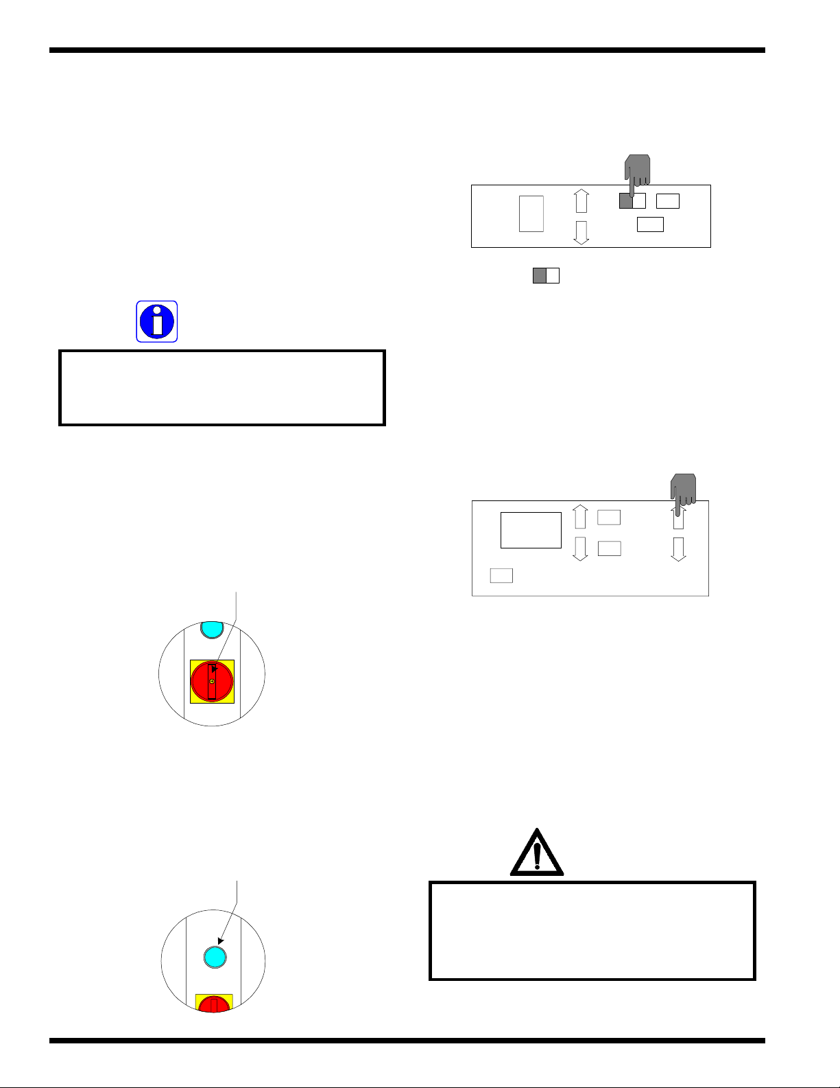
Operations
g
F - 160 Operation and Maintenance Manual
k) Y ou may now begin mounting from the front
operating position.
5.5.2 Pull roller manual nip
adjustment
INFORMATION
If the main laminating rollers are heated,
mounting application may be run from the
rear operating position of the machine.
c) Press SEL.
JOB
SEL
0
SHUT DOWN
=
Flashin
SAV
d) Press FWD s for a forward motor direction.
a) T urn the MAIN POWER to the “ON”
position.
Power
b) Press RESET. The front control panel will
illuminated.
Reset
FWR
REV.
00.0
SPEED
SAFETY
GO
STOP
e) Bring the footswitch around to the rear of the
laminator.
WARNING
Caution should always be exercised
when using the laminator with
the safety shields raised.
You can be seriously HURT or INJURED!
© GBC Pro - Tech August 1999Page 5 - 20
Page 86

F - 160 Operation and Maintenance Manual
f) Raise the rear safety shield.
g) Position the leader board in the center of the
pull rollers between the nip.
CAUTION
Operations
CAUTION
Excess pressure can damage the laminating
rollers. Always use the minimum roll
pressure necessary to complete the task.
Sharp edges on a substrate should be filed
smooth and GAP manually adjusted.
Sharp edges can CUT the rollers!
WARNING
Keep hands and fingers clear of the pull
roller nip when changing the gap.
You can be CRUSHED!
g) At eye level with the pull rollers, turn the pull
roll crank handle clockwise until you see the
upper pull roller make contact with the
substrate.
INFORMATION
Excessive pressure will cause the
substrate to bow or flatten.
INFORMATION
Density of the substrate will determine the
amount of pressure you may use.
INFORMATION
Refer to Figure 5.5.2 for proper roller
pressure.
DOWN
© GBC Pro - Tech August 1999 Page 5 - 21
Page 87

Operations
Figure 5.5.2 Pull roller pressure
F - 160 Operation and Maintenance Manual
CAUTION
Leader board
Leader board
Proper
pressure
Excessive
pressure
Speed is controlled through the variable
speed footswitch when the safety shield
is in the raised position.
h) The pull roller nip has now been manually set.
i) Press STOP .
FWR
REV.
0.00
SPEED
SAFETY
GO
STOP
WARNING
When operating the laminator using the
variable speed footswitch, keep hands and
fingers away from the nip of the rollers.
You may be CRUSHED or BURNED!
g) Step on the variable speed footswitch to back
the leader board out.
j) Press REV t for a reverse motor direction.
FWR
REV.
00.0
SPEED
SAFETY
GO
STOP
k) Y ou may now begin mounting from the rear
operating position.
© GBC Pro - Tech August 1999Page 5 - 22
Page 88

F - 160 Operation and Maintenance Manual
Operations
5.6 Infeed tables
These tables are part of the Falcon 160 safety
features. It is neccessary to have the two infeed tables
properly positioned before running the laminator.
CAUTION
If not installed properly, you can be injured
or cause damage to the table or laminator.
Figure 5.6.1 Front edge
Front edge
5.6.2 Replacing the infeed
table
5.6.1 Removing the table
WARNING
Caution should always be exercised
when using the laminator with
the safety shields raised.
You can be seriously HURT or INJURED!
a) Raise the safety shield.
a) Ensure the safety shiled is in the raised
position.
b) With both hands, grip the front edge of the
infeed table and align the back edge with the
support bolts. Refer to Figure 5.6.2
Figure 5.6.2 Back edge
Front
support bolt
b) With both hands, grip the front edge of the
infeed table and lift up and then out. Refer to
Figure 5.6.1
© GBC Pro - Tech August 1999 Page 5 - 23
Page 89

Operations
c) Now lower the front edge while ensuring that
the pin aligns with the safety roller switch and
the back support bolt. Refer to Figure 5.6.3
INFORMATION
If the tables are not properly seated, the
laminator will not operate in
"Panel" mode.
Figure 5.6.3 Safety roller switch
F - 160 Operation and Maintenance Manual
Safety
roller switch
Back
support bolt
© GBC Pro - Tech August 1999Page 5 - 24
Page 90

F - 160 Operation and Maintenance Manual
Section 6 Applications
T o assist you with a variety of web ups, please
refer to the process control charts and diagrams.
Process control charts allow you to record the
way you thread film through the machine’s rollers
( called webbing ) and the control settings for each
application with regards to your products.
This section contains a blank process control
chart and diagram for the Falcon 160 as well as
completed charts and diagrams for the basic operations
of the laminator. It is recommended that you make
copies of the blanks and fill them in as needed.
WARNING
Do not wear ties, loose fitting clothing or
dangling jewelry while operating or
servicing the laminator. These items can get
caught in the nip and choke you or you can
be crushed or burned.
Applications
6.1 Precoating substrates
This application may be performed from the
front of the laminator using the main rollers or from the
rear of the laminator using the pull rollers in the event
the main rollers are heated. This application is explained
in detail using the main rollers at the front operating
position of the laminator. Use Chart 1 and Diagram 1
for assistance.
Materials needed
• Roll of Pro Mount or Premium Mount adhesive
( or comparable material )
• Substrates to precoat
( Foamcore, Gator Board, etc....)
• Leader board
• Trailer board
• Second person
• Utility knife
• Cutting blade with an enclosed casing.
INFORMATION
The procedures and parameters described
in this section are reference points only .
Parameters will vary with regards to laminate
thickness, laminate widths, laminate types, print
types, ink or toner types, environment conditions,
operator experience and various substrates.
The mount adhesive must not exceed 1 in.
the width of the substrate. If it does, you
may experience complications with this
application.
Set up
Group 1 : No heat
a) Cut two leader boards 6 inch in length of the
No heat applications do not require heat to
activate the adhesive.
© GBC Pro - Tech August 1999 Page 6 - 1
material you are about to precoat.
Page 91

Applications
CAUTION
Sharp edges on a substrate should be filed
smooth and GAP manually adjusted.
Sharp edges can CUT the rollers!
b) Place these two pieces by the laminator for
future use.
INFORMATION
F - 160 Operation and Maintenance Manual
Figure 6.1.1 MAIN POWER / RESET
RESET
MAIN POWER
Rear of the laminator
The two pieces cut in step "a" will be
used as the leader board and trailer
board. These two pieces can be saved
and reused for other applications.
c) Turn MAIN POWER to “ON”. Refer to
Figure 6.1.1
d) Press RESET. Refer to Figure 6.1.1
e) Be sure the front and rear tables are in position
and the pull rollers are in the up position.
f) Raise the rear safety shield.
g) Lift the clevis pin located in the saddle of the
upper unwind shaft.
Saddle
Clevis pin
h) Swing the upper unwind shaft out enough to
slide the roll of mount adhesive over the core
chucks and onto the upper unwind shaft. Refer
to Figure 6.1.2.
WARNING
Caution should always be exercised
when using the laminator with
the safety shields raised.
You can be seriously HURT or INJURED!
INFORMATION
Twisting the roll of laminate while sliding
makes loading the film onto the unwind
shaft easier.
© GBC Pro - Tech August 1999Page 6 - 2
Page 92

F - 160 Operation and Maintenance Manual
Figure 6.1.2 Unwind shaft
Applications
WARNING
Saddle
Core support
Brake adjust
knob
Clevis pin
Roll of
adhesive
Core chucks
i) Once loaded, swing the upper unwind shaft back
into the saddle.
Caution should always be exercised
when using the laminator with
the safety shields raised.
You can be seriously HURT or INJURED!
INFORMATION
If you have the parameters stored as a
JOB number enter it now then press
SEL and skip to step " o", other wise
continue with step " l".
CAUTION
Ensure the roll of laminate is loaded
properly on the unwind shaft.
Exposed adhesive should be facing
away from the rollers.
This will prevent hours of roll cleaning!
j) Push the clevis pin back down to secure the
unwind shaft in its saddle.
l) Press SEL. SEL will stop flashing.
JOB
SEL
0
SHUT DOWN
SAV
WARNING
Keep hands and fingers clear of the
laminator roller nip when changing GAP.
You can CRUSHED or BURNED!
k) Raise the front safety shield.
© GBC Pro - Tech August 1999 Page 6 - 3
Page 93

Applications
F - 160 Operation and Maintenance Manual
CAUTION
Sharp edges on a substrate should be filed
smooth and GAP manually adjusted.
Sharp edges can CUT the rollers!
m) Press GAP
tt
t to the required gap setting for
tt
the substrate being used. The GAP DISPLA Y
should reflect your desired setting.
GAP
PRESSURE
1/4
WARNING
When operating the laminator using the
variable speed footswitch, keep hands and
fingers away from the nip of the rollers.
You may be CRUSHED or BURNED!
o) Press on the variable speed footswitch while
guiding the leader board into the nip to confirm
that the board is secure.
CAUTION
Speed is controlled through the variable
speed footswitch when the safety shield
is in the raised position.
INFORMATION
If the thickness of the substrate is not
known, follow the procedure to manually
set the nip in Section 5.5.1 Manual nip
adjustment.
n) Press FWD
ss
s.
ss
00.0
SPEED
SAFETY
GO
FWR
REV.
STOP
WARNING
Keep hands and fingers clear of
the laminator roller nip when
adjusting PRESSURE.
You can be CRUSHED or BURNED!
p) If the board is loose, press PRESSURE
tt
t to
tt
adjust the gap between the main rollers.
GAP
PRESSURE
1/4
© GBC Pro - Tech August 1999Page 6 - 4
Page 94

F - 160 Operation and Maintenance Manual
Applications
INFORMATION
Excessive pressure will cause the
substrate to bow or flatten.
q) Press STOP.
FWR
REV.
00.0
SPEED
SAFETY
GO
STOP
CAUTION
Speed is controlled through the variable
speed footswitch when the safety shield
is in the raised position.
Process
a) Pull the roll of mount adhesive straight down
toward the front infeed table so that
approximately 6 in. is resting on the front infeed
table. Refer to Figure 6.1.3
r) Press REV
tt
t to reverse the direction of the
tt
Figure 6.1.3 Leader board
motor.
FWR
REV.
00.0
SPEED
SAFETY
GO
STOP
WARNING
When operating the laminator through the
variable speed footswitch, keep your hands
away from the nip of the rollers. You may
be crushed or burned.
Mount
adhesive
Leader
board
b) Position the leader board so that half is adhered
to the mount adhesive. Refer to Figure 6.1.3
INFORMATION
s) Press on the variable speed footswitch to back
the board out of the main rollers.
Position the leader board squarely
onto the mount adhesive.
© GBC Pro - Tech August 1999 Page 6 - 5
Page 95

Applications
F - 160 Operation and Maintenance Manual
c) Press ST OP.
00.0
SPEED
SAFETY
d) Press FWD
ss
s.
ss
GO
STOP
FWR
REV.
e) Push the leader board into the main roller nip
while stepping on the variable speed footswitch.
CAUTION
Speed is controlled through the variable
speed footswitch when the safety shield
is in the raised position.
f) Apply the minimum amount of brake tension on
the roll of mount adhesive to prevent it from
free spinning.
FWR
REV.
00.0
SPEED
SAFETY
GO
STOP
INFORMATION
Steps " e" and " f" will be performed
simultaneously.
INFORMATION
Excessive tension will cause the
substrate to bow.
g) Have the second person stand at the rear of the
laminator.
WARNING
When operating the laminator using the
variable speed footswitch, keep hands and
fingers away from the nip of the rollers.
You may be CRUSHED or BURNED!
INFORMATION
Steps " h" and "i" will be performed
simultaneously.
© GBC Pro - Tech August 1999Page 6 - 6
Page 96

F - 160 Operation and Maintenance Manual
Applications
WARNING
When operating the laminator using the
variable speed footswitch, keep hands and
fingers away from the nip of the rollers.
You may be CRUSHED or BURNED!
h) W ith the stack of substrates within reach of the
first person, step on the variable speed
footswitch while sliding one board in after the
leader board with a 1/2 in. gap between the
two. Refer to Figure 6.1.4
INFORMATION
The 1/2 in. gap between boards will allow
for easier separation of the boards by
the second person.
WARNING
Keep hands and fingers clear of the pull
roller nip when changing the gap.
You can be CRUSHED!
CAUTION
Speed is controlled through the variable
speed footswitch when the safety shield
is in the raised position.
Figure 6.1.4 ( 1/2 in. ) Gap
Substrate
1/2" Gap
i) The person at the rear of the laminator will guide
and lower the upper pull roller onto the leader
board as it passes through the nip opening.
INFORMATION
Do not lower the pull roller so that the
substrate is crushed when passing through.
This will prevent the boards from bowing.
j) As the boards come through, the person at the
rear of the machine will use the utility knife to
Precoated board
separate the boards.
© GBC Pro - Tech August 1999 Page 6 - 7
Page 97

Applications
Caution should always be exercised
F - 160 Operation and Maintenance Manual
Figure 6.1.5 Trailer board
CAUTION
when using a knife .
Sharp knife can cut you!
CAUTION
Caution should always be exercised when
using a utility knife near the rollers.
You can put cuts into the rollers!
k) Inform the second person of the last board to
be precoated before feeding the trailer board
into the main roller nip. Refer to Figure 6.1.5
Precoated
board
Trailer
board
m) Stop the laminator when the trailer board is in
the main roller nip. Refer to Figure 6.1.5
INFORMATION
Do not stop in the middle of a board, an
impression of the roller footprint will be
evident on the board. This can cause a
tunnel effect in the mounting process.
INFORMATION
Before stopping the rollers, position the pull
rollers up. This will prevent an impression
in the last pre-coated board.
l) The second person will raise the rear pull roller
by turning the crank handle counterclockwise
until separated.
n) Trim any excess mount adhesive from the
boards.
CAUTION
Caution should always be exercised
when using a knife .
Sharp knife can cut you!
© GBC Pro - Tech August 1999Page 6 - 8
Page 98

F - 160 Operation and Maintenance Manual
Applications
Finishing
a) Cut the web of mount adhesive at the upper
unwind shaft with an enclosed blade.
CAUTION
Do not use an open blade to cut
the web near the rollers.
You can put cuts into the rollers!
b) Pull the precoated board and trailer board out
from the laminator.
d) Remove the roll of material from the upper
unwind shaft.
e) Press STOP.
FWR
REV.
00.0
SPEED
SAFETY
GO
STOP
f) Clean the rollers as described in the maintenance
section. ( Section 8.2 Cleaning the rollers )
INFORMATION
This will prevent any exposed adhesive from
contacting the rollers.
c) Raise the main rollers to a 1 in. gap by pressing
ss
GAP
s.
ss
GAP
PRESSURE
1
g) Lower the front and rear safety shields and
press SHUTDOWN if finished with the
laminator.
JOB
SEL
0
SHUT DOWN
SAV
End of application
© GBC Pro - Tech August 1999 Page 6 - 9
Page 99

Applications
6.2 Mounting only
F - 160 Operation and Maintenance Manual
Figure 6.2.1 MAIN POWER / RESET
This application may be performed from the
front of the laminator using the main rollers or from the
rear of the laminator using the pull rollers in the event
the main rollers are heated. This application is explained
in detail using the main rollers from the front of the
laminator . Use Chart 2 and Diagram 2 for assistance.
WARNING
Do not wear ties, loose fitting clothing or
dangling jewelry while operating or
servicing the laminator. These items can get
caught in the nip and choke you or you can
be crushed or burned.
RESET
MAIN POWER
Rear of the laminator
c) Be sure the front and rear tables are in position
and the rear pull rollers are in the up position.
d) Raise the front and rear safety shields.
Materials needed
• Prints
• P .S.A. mount boards
• Utility knife
• Leader board
Set up
a) Turn MAIN POWER to “ON”. Refer to
Figure 6.2.1
b) Press RESET. Refer to Figure 6.2.1
WARNING
Caution should always be exercised
when using the laminator with
the safety shields raised.
You can be seriously HURT or INJURED!
INFORMATION
If you have the parameters stored as a
JOB number enter it now then press
SEL and skip to step " h", other wise
continue with step " e".
© GBC Pro - Tech August 1999Page 6 - 10
Page 100

F - 160 Operation and Maintenance Manual
e) Press SEL. SEL will stop flashing.
JOB
0
SEL
SHUT DOWN
WARNING
Keep hands and fingers clear of the
laminator roller nip when changing GAP.
You can be CRUSHED or BURNED!
SAV
Applications
WARNING
When operating the laminator using the
variable speed footswitch, keep hands and
fingers away from the nip of the rollers.
You may be CRUSHED or BURNED!
h) Press on the variable speed footswitch while
guiding the leader board into the nip to confirm
that the board is secure.
f) Press GAP
tt
t to the required gap setting for
tt
the substrate being used. The GAP DISPLA Y
should reflect your desired setting.
GAP
PRESSURE
1/4
g) Press FWD
ss
s.
ss
CAUTION
Speed is controlled through the variable
speed footswitch when the safety shield
is in the raised position.
WARNING
Keep hands and fingers clear of
the laminator roller nip when
adjusting PRESSURE.
You can be CRUSHED or BURNED!
i) If the board is loose, press PRESSURE
tt
t to
tt
adjust the gap between the main rollers.
00.0
SPEED
SAFETY
GO
STOP
FWR
REV.
GAP
1/4
PRESSURE
© GBC Pro - Tech August 1999 Page 6 - 11
 Loading...