

Page 1
Instruction Manual
쮕
Bedienungsanleitung
Manuale d’istruzioni
Page 2

English 4
Deutsch 8
Italiano 12
Page 3
Wire No. Diameters Document Width
3 3/16” (4.8mm) 1/8” (2.5mm)
4 1/4” (6.4mm) 3/16: (4.8mm)
5 5/16” (7.9mm) 1/4” (6.4mm)
6 3/8” (9.5mm) 5/16” (7.9mm)
7 7/16” (11.1mm) 3/8” (9.5mm)
8 1/2” (12.7mm) 7/16” (11.1mm)
9 9/16” (14.3mm) 1/2” (12.7mm)
10 5/8” (15.9mm) 9/16” (14.3mm)
12 3/4” (19mm) 5/8” (15.9mm)
14 7/8” (22.2mm) 3/4” (19mm)
16 1” (25.4mm) 7/8” (22.2mm)
20 1-1/4” (31.8mm) 1” (25.4mm)
Wire 3:1 pitch
A4 : 34 holes
A5 : 24 holes
Wire 2:1 pitch
A4 : 23 holes
A5 : 16 holes
11
22
33
44
55
66
77
88
99
1100
1111
1122
1133
1144
1155
1166
1177
1188
Page 4
4
21
3
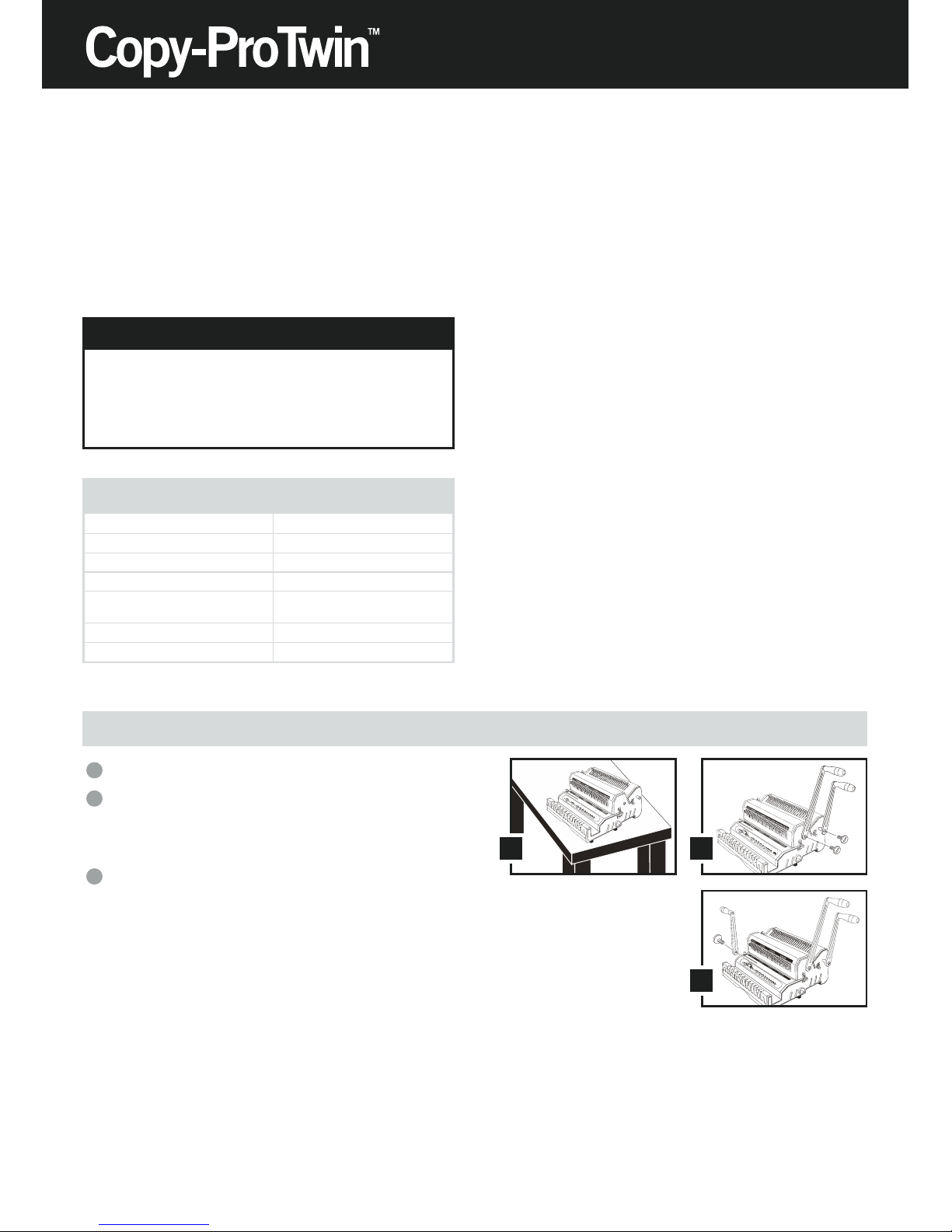
Assembly
Place your new Copy-ProTwin on top of a sturdy working table.
Remove the Screw from Punching Axle clockwise as indicated,
connect 2 Punch Handles, the longer one for 3:1 and the shorter
one for 2:1 in a vertical position onto the Punch Axle. Tightenback the Screws counter-clockwise.
Repeat the same for Closing Handle (the shorter one).
3
2
1
CONGRATULATIONS ON THE PURCHASE OF YOUR
COPY-PRO TWIN, A PROFESSIONAL AND HEAVY
DUTY WIRE PUNCH AND BINDING MACHINE. YOUR
COPY-PRO TWIN WAS DESIGNED WITH A FULL
RANGE OF FUNCTIONS AND PREMIUM QUALITY
COMPONENTS TO GUARANTEE YOU AN
EFFORTLESS AND PROFESSIONAL BIND, AS WELL
AS MANY YEARS OF TROUBLE-FREE SERVICE.
Important
WE RECOMMEND THAT YOU TAKE A FEW MINUTES TO
FAMILIARISE YOURSELF WITH THE FUNCTIONS OF YOUR
NEW COPY-PRO TWIN. YOU WILL FIND THAT WITH JUST A
LITTLE PRACTICE, ANY PERSON CAN ACHIEVE
PROFESSIONAL RESULTS.
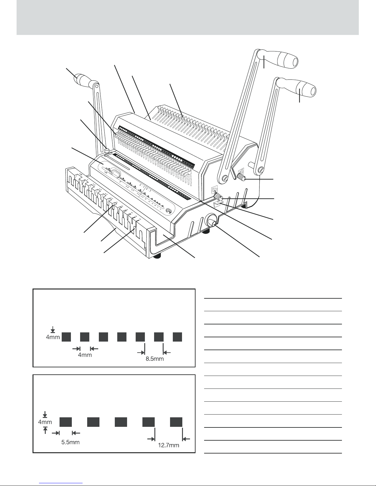
Master Selector:
- Pitch
- Wire Size
- Wire CLosure
- Depth Margin
Side Margin Control for 3:1
Die Disengagement Pins 3:1
Closer Handle
Side Margin Control for 2:1
Punch Throat & Ruler for 2:1
Die Disengagement Pins 2:1
Punch Handle for 3:1
Punch Handle for 2:1
Depth Margin Control for 2:1
Depth Margin Control for 3:1
Continuous Punch Guide
Punch Throat & Ruler for 3:1
Wire Closer Control
Wire Closer
Wire Snatch
Waste Drawer
Diameter Scale
Specifications
Dimensions (HxWxD)
Weight
Punch Capacity
Bind Capacity
Maximum Sheet Width
Dis-engagable Pins
Copy-ProTwin
521 x 711 x 413mm
24kg
Max. 20 sheets (80gsm)
3:1: 125 sheets (14mm)
2:1: 280 sheets (32mm)
14” (356mm)
28 (2:1), 40 (3:1)
Page 5
5
21
43
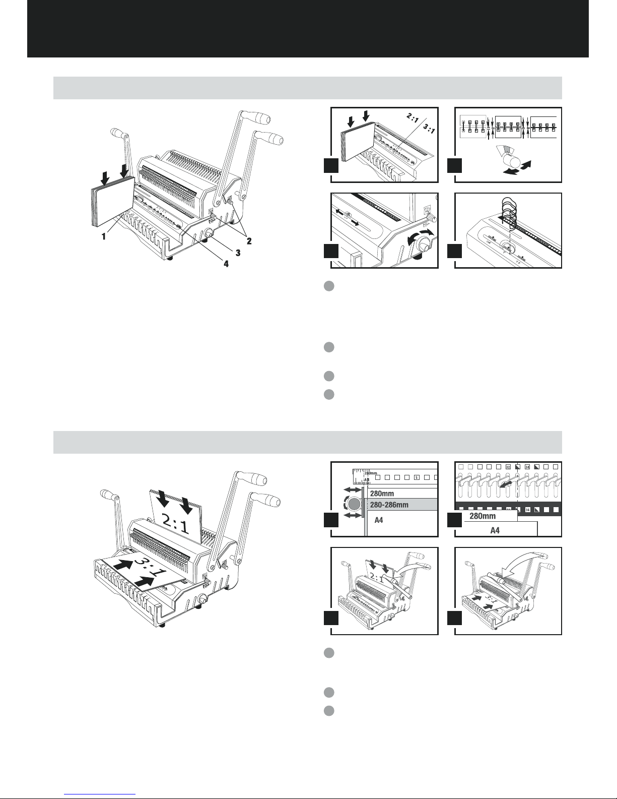
Set-up
Read the Selector to determine the correct:
• Pitch (3:1 or 2:1)
• Depth Margin
• Wire Size
• Wire Closure
Set Depth Control to the colour determined depth margin. Colour
indicated on Depth Control should match colour on Selector.
Set Wire Closer Control to the determined wire closure size.
Read the determined wire size and set aside.
4
3
2
1
Insert a full unbound document into Paper Scale.
TIPS: There may be a different size of 3:1 or 2:1 on some wire
diameters than the standard, please make sure your on-hand
wire is adapted before punching 3:1 or 2:1.
21
3b3a
Punching
Move Side Margin Control to proper sheet and cover size.
Note: There are different side margins for 11” sheets and their
11
1
⁄4” Covers.
Pull out disengagement pins for partially covered holes.
Insert sheets and pull handle forward to punch.
3
2
1
TIPS: Maximum single punching:
20 sheets of 20lbs / 70-80g/m paper.
Comfortable single punching:
12-15 sheets of 20lbs / 70-80g/m paper.
Punch inner sheets and cover separately as side margin
may vary.
Re-Align (Centre) margins for oversize covers.
Page 6
6
2
3
1
3
/
1
6
"
1
/
4
"
5
/
16
"
3/
8
"
7
/
1
6
"
1/2
"
1
1
/
4
"
1
"
7
/
8
"
3
/4
"
5
/
8
"
9
/
1
6
"
7/
8
"
1
"
1
1
/
4
"
3
/
4
"
5
/8
"
9
/
16
"
1
/
2
"
7
/
1
6
"
3
/
8
"
5
/
1
6
"
1
/
4
"
3
/
16
"
2
:
1
3
:
1
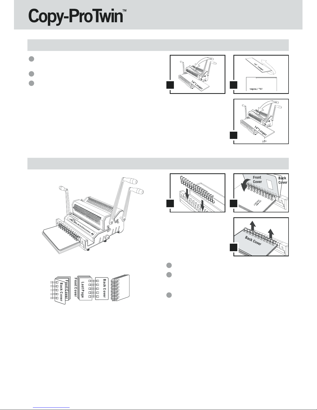
Inserting
Insert pre-selected wire into wire snatch.
Insert document from last pages to first pages then insert
front cover. The back cover should be inserted last with inside
facing up.
Take out inserted document from wire snatch to close the wire.
3
2
1
TIPS: The seam of closed wire should be inside the book. Follow step
No.2 instruction for best results.
21
3
For punching documents larger than 14” (356mm)
Align Sheets as indicated on Punch Throat Ruler. Insert sheets
and pull handle forward to punch the left part first.
Remove sheets and flip them over as illustrated.
Insert sheet from right-hand side. Pull the handle forward and
punch.
IMPORTANT: Document must be inserted in such a way as to place
one of the already perforated holes onto the Continuous
Punch Guide.
3
2
1
Page 7

7
2
3
1
Closing
Put inserted document into wire closer. The wire element must
stand horizontally at the bottom of closer.
Pull closer handle forward to close.
Take out document and turn back cover over. The binding is
ready.
3
2
1
TIPS: The seam of closed wire should be just touching. Slightly adjust
the Closer Control a little left or right for the under-closed or
over-closed seam.
Warranty Policy
GBC Europe (Document Finishing Group) offer the following
warranty.
GBC Europe warrants all new equipment to be free of defects, poor
workmanship or faulty materials for the period of 12 calendar months
effective from the date of delivery.
This warranty does not cover equipment, parts or accessories that have
failed due to wear and tear incurred in the normal use of the equipment.
GBC Europe will support this warranty on site for the first 90 days following
the date of delivery.
Warranty response after this period will be supported on a return to base
system, whereby the customer will be responsible for all costs incurred
transporting the equipment to GBC’s nominated return address.
GBC reserve the right to refuse to accept a ‘return to base’ request
and may alternatively at its discretion attend the customers' premises
to carry out any warranty investigation and subsequent repairs that may
be required.
If a customer requires an on-site visit for a warranty claim or makes a
‘return to base’ warranty claim that proves to be unfounded or inadmissible
under the terms of the warranty, the customer will be charged at the
prevailing callout rate. Parts that are required for a product failure that
does not meet warranty criteria will be charge at the list price in force at
this time.
GBC Europe at its absolute discretion reserve the right to repair the unit or
replace with a unit of similar age.
Please note that GBC’s standard Conditions of Contract and Sale apply in
all aspects of any warranty claim.
Register this product online at www.gbceurope.com
Page 8

8
21
3
Montage
Stellen Sie Ihre neue COPY-PRO TWIN auf einen stabilen
Arbeitstisch.
Drehen Sie die Schrauben auf der rechten Seite des Gerätes wie
angegeben im Uhrzeigersinn aus der Stanzachse heraus, bringen
Sie die 2 Stanzhebel in senkrechter Position auf der Stanzachse
an, den längeren Heble für 3:1 und den kürzeren Hebel für 2:1.
Ziehen Sie die Schraube entgegen dem Uhrzeigersinn wieder fest.
Wiederholen Sie den Vorgang für den Bindehebel auf der linken
Hebel (den kürzeren).
3
2
1
HERZLICHEN GLÜCKWUNSCH ZUM KAUF IHRER
COPY-PRO TWIN, EINEM PROFESSIONELLEN UND
HOCHLEISTUNGSFÄHIGEN STANZ- UND
DRAHTBINDEGERÄT. IHRE COPY-PRO TWIN
VERFÜGT ÜBER EIN UMFANGREICHES
FUNKTIONSSPEKTRUM UND IST MIT
HOCHWERTIGEN KOMPONENTEN VERSEHEN, UM
IHNEN EIN MÜHELOSES UND PROFESSIONELLES
BINDEN UND EINEN STÖRUNGSFREIEN BETRIEB
ÜBER VIELE JAHRE HINWEG ZU ERMÖGLICHEN.
Wichtig
WIR EMPFEHLEN IHNEN, SICH EIN PAAR MINUTEN ZEIT
ZU NEHMEN, UM SICH MIT DEN FUNKTIONEN IHRER
NEUEN COPY-PRO TWIN VERTRAUT ZU MACHEN. SIE
WERDEN FESTSTELLEN, DASS SIE MIT ETWAS ÜBUNG,
PROFESSIONELLE ERGEBNISSE ERZIELEN WERDEN.
Auswahlvorrichtung:
- Teilung 3:1 oder 2:1
- Drahtgröße
- Binde-Durchmesser
- Stanztiefe
Seitenrandeinstellung für 3:1
Herausziehbare Stanzstifte 3:1
Bindehebel
Seitenrandeinstellung für 2:1
Stanzschacht und Mess-Skala für 2:1
Herausziehbare Stanzstifte 2:1
Stanzhebel für 3:1
Stanzhebel für 2:1
Stanztiefeneinstellung für 2:1
Stanztiefeneinstellung für 3:1
Dauerstanzführung
Stanzschacht und Mess-Skala für 3:1
Schließleisteneinstellung
Schließleiste
Drahteinführung
Abfall-Schublade
Auswahlhilfe Drahtgröße
Technische Daten
Abmessungen
Gewicht
Stanzleistung
Bindekapazität
Max. Bogenbreite
Stanztiefe
Copy-ProTwin
521 x 711 x 413 mm
24 kg
Max. 20 Blatt (80 g/m
2
)
3:1: 125 Blatt (14 mm)
2:1: 280 Blatt (32 mm)
14” (356 mm)
28 (2:1), 40 (3:1)
Page 9

쮕
9
21
43
Einrichten
Legen Sie ein vollständiges, ungebundenes Dokument in die
Auswahlhilfe Drahtgröße ein.
TIPPS: Bei einigen Drahtdurchmessern kann die Größe von 3:1 oder
2:1 unter Umständen vom Standard abweichen. Vergewissern
Sie sich bitte vor dem Stanzen von 3:1 oder 2:1 Teilungen,
dass der Ihnen zur Verfügung stehende Draht geeignet ist.
21
3b3a
Lochen
Bewegen Sie den Seitenrandeinsteller in die richtige Position für
die Blatt- und Deckblattgröße.
Hinweis: Die Seitenränder für 11 Zoll Blätter (280 mm) und ihre
11
1
⁄4 Zoll Deckblätter (286 mm) sind verschieden.
Ziehen Sie die Stanzstifte für teilweise verdeckte Löcher heraus.
Legen Sie Blätter ein und ziehen Sie den Hebel nach vorne, um
die Löcher zu stanzen.
3
2
1
TIPPS: Maximale Stanzkapazität:
20 Blatt (70-80g/m
2
)
Bequemes Stanzen:
12-15 Blatt (70-80g/m
2
)
Stanzen Sie die Innenblätter und das Deckblatt getrennt
voneinander, da der Seitenrand abweichen kann.
Richten Sie die Seitenränder für übergroße Deckblätter neu
aus (zentrieren).
Bestimmen Sie durch Ablesen von der Auswahlvorrichtung die
korrekten Werte für:
• Stanzteilung 3:1 oder 2:1
• Stanztiefe
• Drahtgröße
• Binde-Durchmesser
Stellen Sie den Stanztiefeneinsteller auf die farblich bedingte
Stanztiefe ein. Die Farbe auf dem Tiefeneinsteller muss der Farbe
auf der Auswahlhilfe entsprechen.
Stellen Sie die Stanztiefeneinstellung auf den ermittelten BindeDurchmesser ein.
Lesen Sie die ermittelte Drahtgröße ab und halten Sie den
benötigten Draht bereit.
4
3
2
1
Page 10

10
2
3
1
3
/
1
6
"
1
/
4
"
5
/
16
"
3/
8
"
7
/
1
6
"
1/2
"
1
1
/
4
"
1
"
7
/
8
"
3
/4
"
5
/
8
"
9
/
1
6
"
7/
8
"
1
"
1
1
/
4
"
3
/
4
"
5
/8
"
9
/
1
6
"
1
/
2
"
7
/
1
6
"
3
/
8
"
5
/
1
6
"
1
/
4
"
3
/
16
"
2
:1
3
:
1
Einlegen
Führen Sie den zuvor ausgewählten Draht in die Drahteinführung
ein.
Legen Sie das Dokument, beginnend mit der letzten Seite, und
anschließend das Deckblatt ein. Das hintere Deckblatt ist zuletzt
und mit der Innenseite nach oben einzulegen.
Entnehmen Sie das eingelegte Dokument aus der
Drahteinführung, um den Draht zu schließen.
3
2
1
TIPPS: Die Nahtstelle des geschlossenen Drahts sollte sich im Innern
des Buchs befinden. Befolgen Sie Schritt Nr. 2 der Anleitung,
um optimale Ergebnisse zu erzielen.
21
3
Stanzen von Dokumenten über 14 Zoll (356mm)
Legen Sie die Blätter wie angegeben am Lineal der Stanzkehle an
und ziehen Sie den Hebel nach vorne, um zunächst den linken Teil
zu stanzen. Siehe Bild 1.
Entnehmen Sie die Blätter und schlagen Sie sie um, wie auf dem
Bild gezeigt. Siehe Bild 2.
Legen Sie das Blatt von der rechten Seite ein. Ziehen Sie den
Hebel nach vorne und stanzen Sie. Siehe Bild 3.
WICHTIG: Das Dokument ist so einzulegen, dass es mit einem der
bereits gestanzten Löcher auf der Dauerstanzführung liegt.
3
2
1
Page 11

쮕
11
2
3
1
Drahtschleissung
Legen Sie das eingelegte Dokument in die Schließleiste. Das
Drahtelement muss waagerecht am Boden der Schließleiste
stehen.
Ziehen Sie den Bindehebel nach vorne und schließen Sie die
Bindung.
Nehmen Sie das Dokument heraus und schlagen Sie das hintere
Deckblatt um. Die Bindung ist nun fertig.
3
2
1
TIPPS: Die Nahtstellen des geschlossenen Drahts sollten sich gerade
eben berühren. Verstellen Sie die Schließleistensteuerung ganz
leicht nach links oder rechts bei einer zu weit geöffneten bzw.
zu eng geschlossenen Nahtstelle.
Garantieerklärung
GBC Europe (ein Unternehmen der Acco Brands Corporation)
gewährt folgende Garantie.
GBC Europe garantiert die Freiheit von Mängeln, Verarbeitungs- oder
Materialfehlern für alle Neugeräte für die Dauer von 12 Monaten ab
Liefertermin.
Nicht unter diese Garantie fallen Geräte, Teile oder Zubehör, deren
Versagen auf Verschleiß im Zuge des normalen Gebrauchs des Gerätes
zurückzuführen ist.
GBC Europe gewährt diese Garantie in den ersten 90 Tagen nach
Liefertermin vor Ort.
Anschließend erfolgt die Garantiebearbeitung auf der Basis eines
Rücksendesystems, bei dem der Kunde sämtliche anfallenden Kosten für
den Transport zu der von GBC benannten Rücksendeanschrift trägt.
GBC behält sich das Recht vor, die Annahme eines Rücksendeanfrage
abzulehnen und statt dessen nach eigenem Ermessen die Räumlichkeiten
des Kunden aufzusuchen, um Garantieuntersuchungen und unter
Umständen erforderliche Reparaturen durchzuführen.
Sollte im Zuge eines Garantieanspruchs eine Vorort beim Kunden
erforderlich sein oder sollte ein Kunde auf dem Wege der Rücksendung
einen gemäß den Garantiebedingungen unbegründeten oder unzulässigen
Garantieanspruch geltend machen, wird dem Kunden der übliche
Anfahrtbetrag in Rechnung gestellt. Teile, die im Zuge eines
Produktausfalls, der die Kriterien der Garantie nicht erfüllt, benötigt werden,
werden mit dem zu diesem Zeitpunkt geltenden Listenpreis berechnet.
GBC Europe behält sich das Recht vor, die Einheit nach eigenem freien
Ermessen entweder zu reparieren oder gegen eine gleich alte Einheit
auszutauschen.
Bitte beachten Sie, dass die Standardvertrags- und verkaufsbedingungen
von GBC für Garantieansprüche in jeder Hinsicht gelten.
Registrieren Sie dieses Produkt online unter www.gbceurope.com
Page 12

12
21
3
Assemblaggio
Posizionare la nuova COPY-PRO TWIN su un tavolo di lavoro
robusto.
Rimuovere le viti dai cilindri di perforazione ruotandole in senso
orario come in figura e innestare le 2 maniglie per la perforazione
(la più lunga per il passo 3:1 e la più corta per il passo 2:1)
posizionandole verticalmente sui cilindri. Riposizionare le viti e
avvitarle in senso antiorario.
Ripetere la stessa operazione per la maniglia del pressore per
chiusura della spirale metallica (maniglia corta).
3
2
1
CONGRATULAZIONI PER L’ACQUISTO DI COPY-PRO
TWIN, LA MACCHINA PERFORATRICE E
RILEGRATRICE A SPIRALE METALLICA
PROFESSIONALE. COPY-PRO TWIN È STATA
PROGETTATA CON UNA GAMMA COMPLETA DI
FUNZIONI E COMPONENTI DI QUALITÀ SUPERIORE
PER GARANTIRE UNA RILEGATURA FACILE E
PROFESSIONALE, PER MOLTI ANNI DI SERVIZIO
ININTERROTTO.
Importante
SI CONSIGLIA DI DEDICARE ALCUNI MINUTI ALLA
CONOSCENZA DELLE FUNZIONI DELLA NUOVA COPY-PRO
TWIN. CON POCHI ESERCIZI PRATICI OGNI UTENTE PUO’
OTTENERE RISULTATI PROFESSIONALI.
Selettore principale:
- Passo
- Dimensioni spirale metallica
- Chiusura spirale metallica
- Profondità del margine
Controllo del margine laterale per 3:1
Leva per disinserimento punzone stampo 3:1
Maniglia del pressore per chiusura
Controllo del margine laterale per 2:1
Spessore e righello di perforazione per 2:1
Leva per disinserimento punzone stampo 2:1
Maniglia perforazione per 3:1
Maniglia perforazione per 2:1
Controllo di profondità del margine per 2:1
Controllo di profondità del margine per 3:1
Guida continua di perforazione
Spessore e righello di perforazione per 3:1
Controllo di chiusura spirale metallica
Pressore per chiusura spirale metallica
Fermo spirale metallica
Cassetto per i residui della carta
Scala diametro
Caratteristiche tecniche
Dimensioni
Peso
Capacità foratura
Capacità rilegatura
Larghezza massima foglio
Margine foratura
Copy-ProTwin
521 x 711 x 413 mm
24 kg
Max. 20 fogli (80gr)
3:1: 125 fogli (14 mm)
2:1: 280 fogli (32 mm)
14” (356 mm)
28 (2:1), 40 (3:1)
Page 13

13
21
43
Preparazione
Inserire un documento non rilegato nel selettore della carta.
SUGGERIMENTI: Il diametro di alcune spirali metalliche per il passo
3:1 o 2:1 potrebbe essere diverso da quello
standard. Accertarsi che il filo metallico sia adatto
prima di eseguire perforazioni con passo 3:1 o 2:1.
21
3b3a
Perforazione
Spostare il controllo del margine laterale sulla dimensione
appropriata per il foglio e la copertina.
Nota: esistono margini laterali diversi per i fogli da 280 mm e le
rispettive copertine da 286 mm.
Estrarre i pettini di disinserimento per i fori parzialmente coperti.
Inserire i fogli e tirare la maniglia in avanti per la perforazione.
3
2
1
SUGGERIMENTI: Numero massimo di fogli per perforazione:
20 fogli di carta da 70-80 g/m.
Numero ideale di fogli per perforazione:
12-15 fogli di carta da 70-80 g/m.
Perforare separatamente i fogli interni e la
copertina, in quanto il margine laterale può variare.
Riallineare (centrare) i margini per le copertine di
dimensioni maggiori.
Leggere il selettore per determinare i seguenti valori appropriati:
• Passo di perforazione (3:1 o 2:1)
• Profondità del margine
• Dimensioni della spirale metallica
• Chiusura della spirale metallica
Regolare la profondita’ del margine sul colore determinato dalla
lettura fatta precedentemente sul selettore.
Impostare il controllo di chiusura della spirale metallica sulla
dimensione di chiusura determinata dalla lettura fatta
precedentemente sul selettore.
Leggere tale dimensione e annotarla.
4
3
2
1
Page 14

14
2
3
1
3
/
1
6
"
1
/
4
"
5
/
16
"
3/
8
"
7
/
1
6
"
1/2
"
1
1
/
4
"
1
"
7
/
8
"
3
/4
"
5
/
8
"
9
/
1
6
"
7/
8
"
1
"
1
1
/
4
"
3
/
4
"
5
/8
"
9
/
1
6
"
1
/
2
"
7
/
1
6
"
3
/
8
"
5
/
1
6
"
1
/
4
"
3
/
16
"
2
:1
3
:
1
Inserimento
Inserire la spirale metallica preselezionata nel fermo spirale
metallica.
Inserire il documento a partire dall'ultima pagina e fino alla prima,
quindi inserire la copertina anteriore. La copertina posteriore
dovrà essere inserita per ultima con la parte interna rivolta verso
l'alto.
Tirare fuori dal fermo spirale metallica il documento inserito per
chiudere la spirale metallica.
3
2
1
SUGGERIMENTI: Le estremita’ di chiusura della spirale metallica
devono trovarsi all'interno del documento rilegato.
Per risultati ottimali, seguire le istruzioni del
passaggio 2.
21
3
Perforazione di documenti di dimensioni maggiori di 356 mm
Allineare i fogli come in figura sul righello e spessore di
perforazione. Inserire i fogli e tirare la maniglia in avanti per
perforare prima la parte sinistra. Vedere figura 1.
Rimuovere i fogli e capovolgerli come in figura. Vedere figura 2.
Inserire i fogli dal lato destro. Tirare la maniglia in avanti e
perforare. Vedere figura 3.
IMPORTANTE: il documento deve essere inserito in modo da
posizionare uno dei fori già praticati sulla guida
continua di perforazione.
3
2
1
Page 15

15
2
3
1
Chiusura
Posizionare il documento inserito nel pressore per chiusura della
spirale metallica. L'elemento della spirale deve essere posizionato
orizzontalmente nella parte inferiore del pressore per chiusura.
Tirare in avanti la maniglia del pressore per chiudere la spirale.
Tirare fuori il documento e capovolgere la copertina posteriore.
La rilegatura è pronta.
3
2
1
SUGGERIMENTI: Le estremita’ di chiusura della spirale metallica
devono toccarsi leggermente. Spostare leggermente
il controllo di chiusura verso sinistra o destra per
raggiungere il posizionamento ottimale.
Dichiarazione di garanzia
GBC Italia (società del gruppo Acco Brands Corporation) offre la
seguente garanzia:
Il prodotto e’ garantito contro vizi e difetti di materiali e/o di fabbricazione
per un periodo di un anno dalla data di acquisto. La garanzia consiste nella
sostituzione o nella riparazione delle parti componenti il prodotto che
risultino difettose.
Sono altresi’ esclusi dalla garanzia i difetti che derivino da uso errato o
improprio , o non conforme alle avvertenze riportate sul libretto di istruzioni,
dall’utilizzo di accessori non originali o comunque causati da fenomeni
estranei al normale funzionamento del prodotto stesso.
In caso di rottura entro 15 giorni lavorativi il trasporto per e da il centro di
riparazione sara’ a completo carico di GBC se il prodotto e’ restituito nel
suo imballo originale.
In caso di rottura dopo i primi 15 giorni lavorativi , il trasporto verso GBC
avra’ luogo a cura, spese e rischio del cliente. Il reso sara’ a carico di GBC.
Allo scopo di evitare che si verifichino danni nel corso del trasporto, e’
indispensabile che il prodotto viaggi esclusivamente nel suo imballo
originale.
La garanzia decade qualora il prodotto sia stato manomesso o riparato da
personale non autorizzato.
GBC e’ in grado di offrire un servizio di Contratti di Assistenza Tecnica per
la riparazione presso la sede del cliente o presso la propria sede.Per
informazioni contattare il numero verde 800-848616.
In caso di intervento presso la sede del cliente , sra’ dovuto a GBC un
diritto fisso di chiamata in vigore alla data dell’intervento.
IN caso il prodotto venga sostituito ad insindacabile giudizio di GBC, sara’
ritenuto valido il periodo di garanzia originale del prodotto sostituito.
Per la registrazione online di questo prodotto, visitare il sito Web all'indirizzo www.gbceurope.com
Page 16

Page 17

Page 18

ACCO Brands Europe
Oxford House, Oxford Road
Aylesbury HP21 8SZ
United Kingdom
www.gbceurope.com
 Loading...