

Page 1
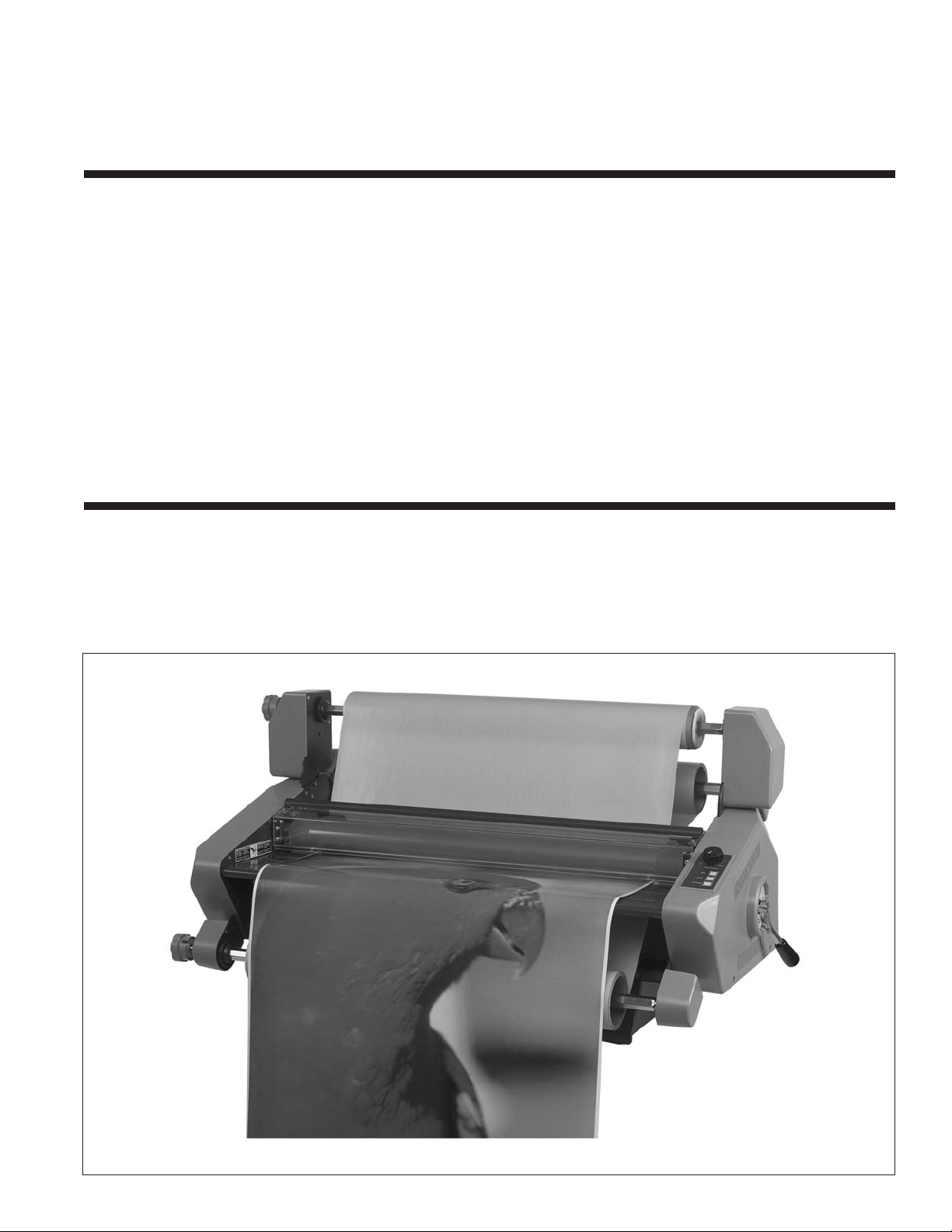
27C Laminator
INSTALLATION &
OPERATION MANUAL
Document Number: 930-121 REV: - REV DATE: 11-24-04
Do not duplicate without written permission.
Page 2

27C
Operating Instructions
Page 2
Page 3

Operating Instructions
TABLE OF CONTENTS
27C
1. Safety
Warnings .................................................................1-1
General ....................................................................1-1
Electrical ..................................................................1-2
2. Warranty
Limited 90-Day Warranty ........................................2-1
3. Specifications
FCC Note ................................................................ 3-2
4. Installation
Prior to Installation ................................................. 4-1
Installation .............................................................. 4-1
5. Feature guide
Top Film Supply Shaft ............................................ 5-1
Release Liner Take-up .......................................... 5-1
Idler Bar .................................................................. 5-1
Pressure Rollers ..................................................... 5-1
Nip Point ................................................................ 5-1
Safety Shield .......................................................... 5-1
Feed Table .............................................................. 5-2
Table Interlock Latch ......................................... 5-2
Bottom Film Supply Shaft ................................ 5-2
Film Web ................................................................ 5-2
Core Adaptors .................................................. 5-2
Roller Pressure Handle ......................................... 5-2
Film and Take-up Tension Adjustment Knobs ... 5-3
Control Panel ..................................................... 5-3
POWER SWITCH .................................................... 5-4
Film Tension ...................................................... 6-11
Testing the Web ............................................6-11
Clearing a Film Jam (Wrap-up) .........................6-12
Lamination Guide .................................................6-1
7. Operator Maintenance
Caring for the 27C Laminator ..................................7-1
Cleaning The Rollers ...........................................7-1
Troubleshooting ......................................................7-2
2
6. Operation
General Operation .................................................. 6-1
Loading Film ........................................................... 6-2
Removing and Installing the Safety Shield ........ 6-3
Removing and Installing the Feed Table ........... 6-3
Loading Film Onto the Supply Shafts ................ 6-4
Loading Film with a Threading Card ................. 6-6
Loading Film by Tacking New Film to Existing Film
6-7
Decaling in Two Passes ......................................... 6-8
Mounting ...............................................................6-10
Tips For Threading Pressure Sensitive Adhesive
(PSA) Film .........................................................6-10
Pre-Treating Boards ..........................................6-10
Mounting Only ..................................................6-10
Film Alignment and Tension ..................................6-10
Film Alignment ..................................................6-10
Page i
Page 4

27C
Operating Instructions
Page ii
Page 5
Operating Instructions
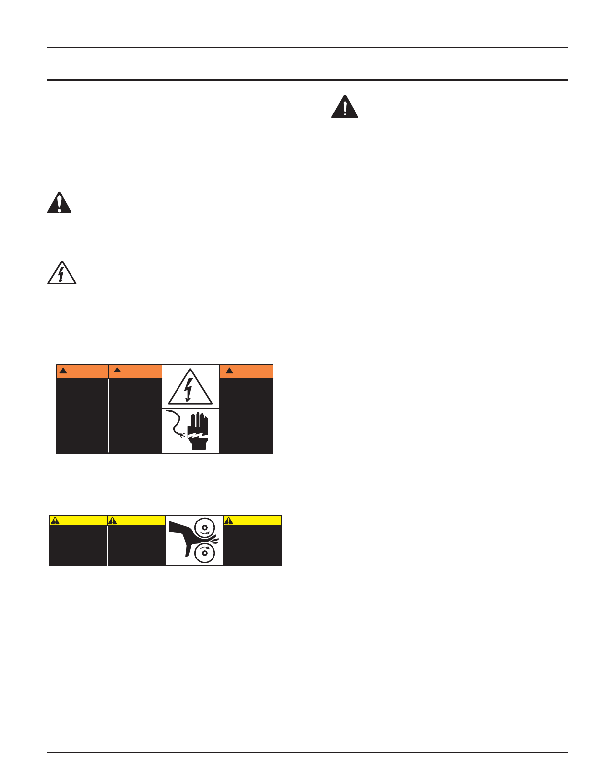
ADVERTENCIA
!
Riesgo de choque
eléctrico
No abra:
Adentro no hay
piezas reparables
por el usuario.
Mantenimiento
solamente por
personal calificado.
ATTENTION
!
Risque de
secousse
électrique.
Ne pas ouvrir:
Pas de pièces
réparables par
l'utilisateur.
Entretien
seulement par
personnel qualifié.
WARNING
!
Electrical shock
hazard.
Do not open.
No user
serviceable
parts inside.
Refer servicing to
qualified service
personnel.
CAUTION
ATTENTION
CUIDADO
PUNTO DE
PINCHAMIENTO
Keep hands and
fingers away
.
Mantener manos
y
dedos a distancia.
Tenir mains et
doigts a l'écar
t.
PINCH POIN
T
between rollers.
POINT DE
PINCEMENT
entre les rouleaux.
entre rodillos.
1. SAFETY
27C
Your safety, as well as the safety of others is
important. Before you install or use the machine,
read and follow all the safety notices carefully in
this chapter. In this instruction manual, and on the
laminator, you will find important safety notices
regarding the laminator. Read all of the instructions
and save these instructions for further use.
The safety alert symbol precedes each
safety notice in this manual. The symbol indicates a
potential personal safety hazard to you or others, as
well as laminator or property damage.
This safety alert symbol indicates a potential
electrical shock. It warns you to not open the
laminator and expose yourself to hazardous voltage.
The following warnings are found on the 27C
laminator.
WARNINGS
Do not attempt to service or repair the
•
laminator.
Do not connect the laminator to an electrical
•
supply or attempt to operate the laminator
until you have completely read these
instructions. Maintain these instructions in a
convenient location for future reference.
To guard against injury, the following safety
•
precautions must be observed when installing
and using the laminator.
Failure to observe these warnings could result in
severe bodily damage or death.
GENERAL
Keep hands, long hair, loose clothing, and
•
articles such as necklaces or ties, away from
the front of the rollers to avoid entanglement
and entrapment
This safety notice means that you could be seriously
hurt or killed if you open the laminator and expose
yourself to hazardous voltage.
This safety notice means that your fingers and
hands could be trapped and crushed in the rollers.
Clothing, jewelry and long hair could be caught in the
rollers and pull you into them.
Do not use the laminator for other than its
•
intended purpose.
Do not place the laminator on an unstable
•
cart, stand or table. An unstable surface may
cause the laminator to fall resulting in serious
bodily injury. Avoid quick stops, excessive
force and uneven floor surfaces when moving
the laminator on a cart or stand.
Do not defeat or remove electrical and
•
mechanical safety equipment such as
interlocks, shields and guards.
Do not insert objects unsuitable for lamination
•
or expose the equipment to liquids.
Page 1-1
Page 6

27C
ELECTRICAL
The laminator should be connected only to a source
of power as indicated in these instructions and on
the serial plate located on the rear of the laminator.
Contact an electrician should the attachment
plug provided with the laminator not match the
receptacles at your location.
WARNING: Do not attempt to service or repair
the laminator. Failure to observe this warning could
result severe personal injury or death.
Disconnect the plug from the receptacle and contact
your dealer/distributor when one or more of the
following has occurred.
The power supply cord or attachment plug is
•
damaged.
Operating Instructions
Liquid has been spilled into the laminator.
•
The laminator is malfunctioning after being
•
mishandled.
The laminator does not operate as described
•
in these instructions.
CAUTION: The receptacle must be located
near the equipment and easily accessible.
Disconnect the attachment plug from the receptacle
to which it is connected and keep the power supply
cord in your possession while moving the laminator.
Page 1-2
Page 7
Page 8

27C
Operating Instructions
Page 2-2
Page 9
Operating Instructions
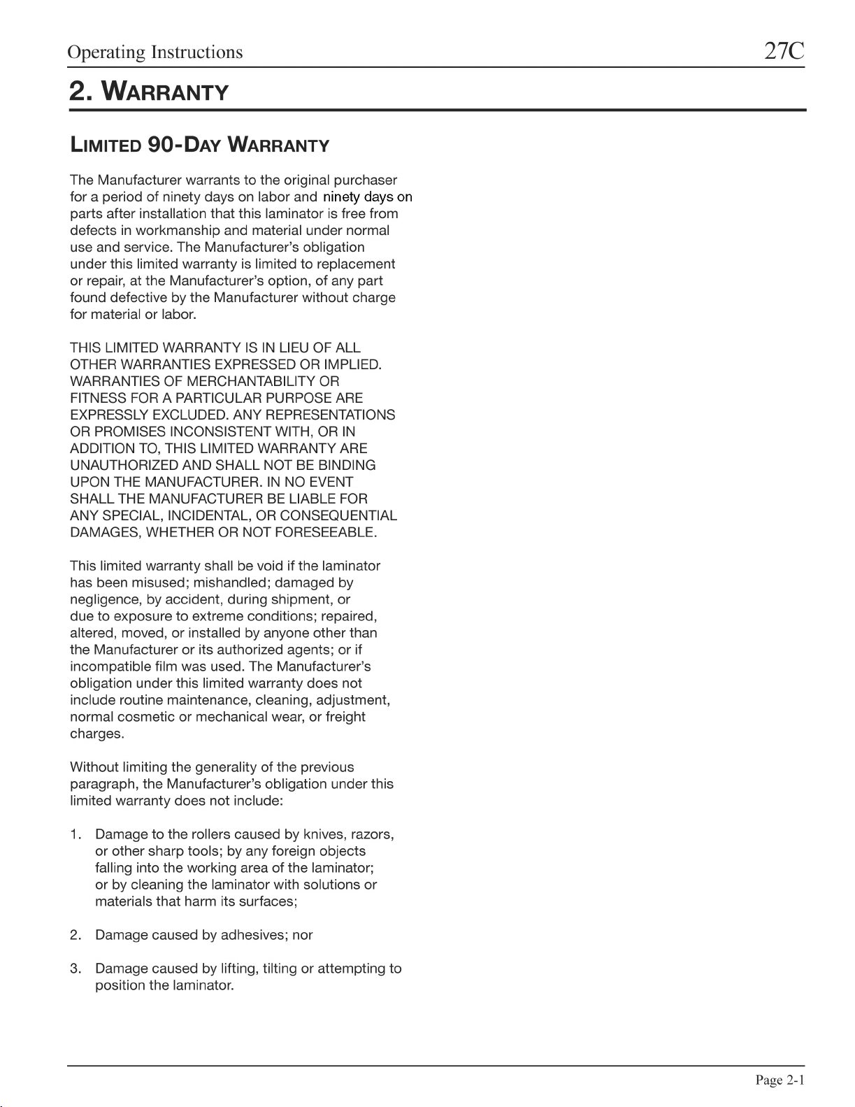
3. SPECIFICATIONS
Operating Speed
Variable
•
Fixed – Safety shield removed
•
Dimensions
Width
•
Height
•
Depth
•
Weight
•
Electrical Requirements
Voltage
•
Current
•
Power
•
U.S. Receptacle
•
27C
2.5 to 15 fpm (0.8 to 4 m)
3 fpm (0.9 m)
39 in (99 cm)
20 in (50.8 cm)
21 in (53 cm)
140 lbs. (64 kg))
120 V 60 Hz
0.6 Amps
50 W
NEMA 5-15R
39 (99 )
Fig. 3-1. 27C Dimensions (Shown in Inches (cm).)
20 (50.8 )
21 (53)
Page 3-1
Page 10

27C
FCC NOTE
This equipment has been tested and found to
comply with the limits for a Class A digital device,
pursuant to part 15 of the FCC Rules. These limits
are designed to provide reasonable protection
against harmful interference when the equipment
is operated in a commercial environment. This
equipment generates, uses, and can radiate radio
frequency energy and, if not installed and used in
accordance with the instruction manual, may cause
harmful interference to radio communications.
Operation of this equipment in a residential area is
likely to cause harmful interference in which case the
user will be required to correct the interference at
his/her own expense.
Changes or modifications not expressly approved by
the manufacturer could void the user’s authority to
operate the equipment.
Operating Instructions
This Class A digital apparatus complies with
Canadian ICES-003.
(Cet appareil numérique de las Classe A est
conforme a la norme NMB-003 du Canada.
Page 3-2
Page 11

Operating Instructions
4. INSTALLATION
27C
This chapter describes how to install the machine.
There are no operator serviceable parts to the
machine other than periodic cleaning. Refer to the
Operator Maintenance chapter.
WARNING: Do not attempt to service or repair
the laminator. Failure to observe this warning could
result severe personal injury or death.
Disconnect the plug from the receptacle and contact
your dealer/distributor when one or more of the
following has occurred.
The power supply cord or attachment plug is
•
damaged.
Liquid has been spilled into the laminator.
•
The laminator is malfunctioning after being
•
mishandled.
The laminator does not operate as described
•
in these instructions.
INSTALLATION
To set up the laminator for the first time:
Place the laminator on a stable flat surface
1.
capable of supporting the weight of the machine
and any materials. The surface should be at least
30 inches (0.76 m) high to assure comfortable
positioning during operation. All four rubber
support feet should be positioned completely on
the supporting surface. The supporting surface
may also be large enough to hold the material to
be laminated.
The laminator should be located so that exiting
2.
film drops freely to the floor or to a table that
is lower than the exit point of the laminator.
Accumulation of laminate immediately behind the
laminator as it exits the equipment may cause
the film to wrap around the rollers, jamming the
machine.
Avoid locating the laminator near sources of heat
3.
or cold. The laminator should not be in the direct
path of forced heated or cooled air.
PRIOR TO INSTALLATION
Inspect the package for damage. Shipping damage
should be brought to the immediate attention of the
delivering carrier.
Connect the attachment plug provided with the
4.
laminator to a suitably grounded outlet only.
Page 4-1
Page 12

27C
Operating Instructions
Page 4-2
Page 13

Operating Instructions
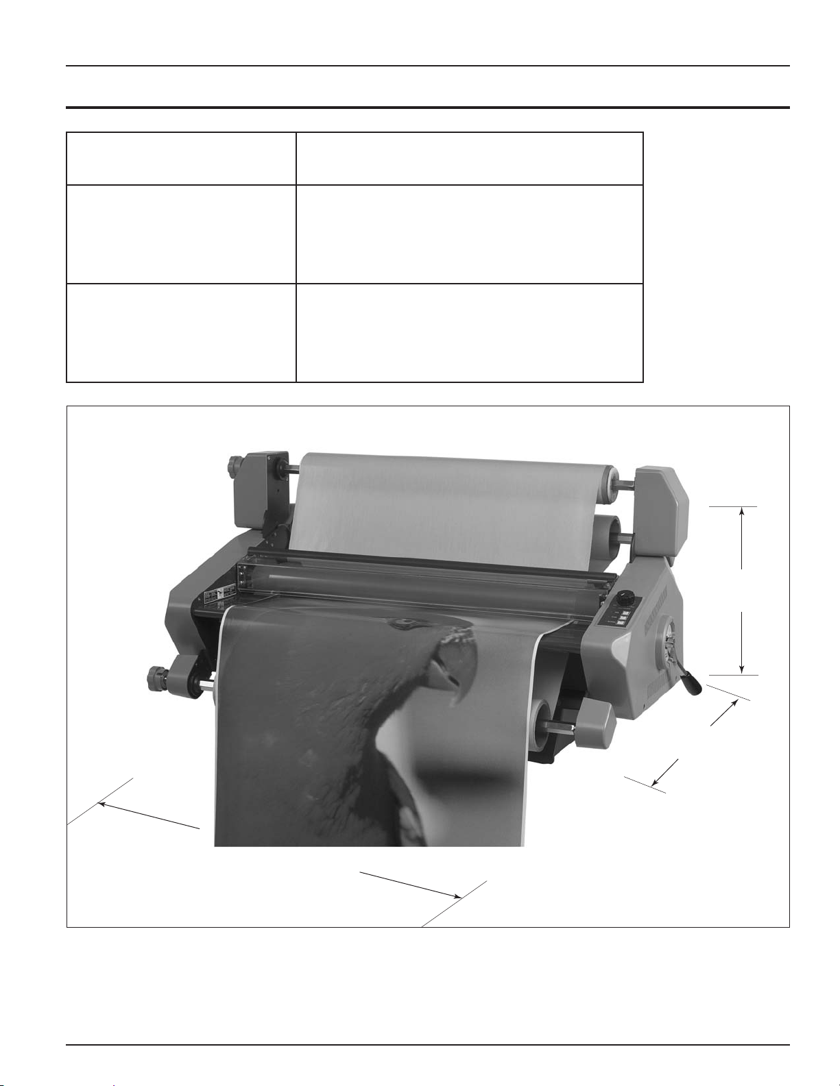
5. FEATURE GUIDE
This chapter helps you identify the main components of the laminator.
27C
Pressure roller
Safety shield
Feed table
Feed table
interlock latch
(under table)
Release liner take-up
Top film supply shaft
Roller pressure
handle
Control panel
Bottom supply shaft
Fig. 5-1. 27C Laminator Identification.
TOP FILM SUPPLY SHAFT
Holds the film supply on the laminator.
RELEASE LINER TAKE-UP
Rewinds the release liner of pressure sensitive films.
IDLER BAR
(Not shown.) The idler bar directs the film to the
roller.
PRESSURE ROLLERS
Two pressure rollers apply pressure to the film and
the print being laminated or mounted. They pull the
print and films into the laminator.
NIP POINT
(Not shown.) The point at which the top and bottom
rollers come into contact and the point at which the
items for lamination are introduced into the laminator.
SAFETY SHIELD
The safety shield prevents entanglement,
entrapment, and inadvertent contact with the rollers.
When the safety shield is removed, the laminator
runs at 3 fpm (0.9 m) when you press the RUN
button. The safety shield is removed only when you
load films.
WARNING: Keep your fingers and hands away
from the nip point. Failure to observe this warning
could result in severe personal injury.
Page 5-1
Page 14
27C
Operating Instructions
FEED TABLE
The feed table is used to position items for
laminating and mounting. When the feed table is
removed, the laminator runs at 3 fpm ( 0.9 m)
when you press the RUN button. The feed table is
removed only when you load film.
TABLE INTERLOCK LATCH
Table interlock latch
Fig. 5-2. Table Interlock Latch Under the Table.
The interlock latch locks the feed table into position
and activates an interlock switch. The latch is located
on the left, underside of the feed table. Move the
latch to the right to release the table. Then lift the
table upwards and away from the laminator.
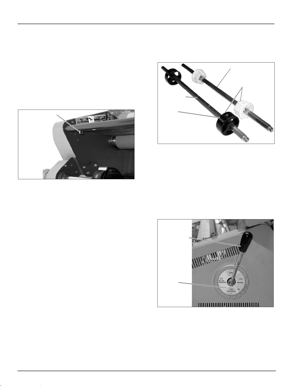
CORE ADAPTORS
Take-up shaft
Core adaptor
Supply shaft
Gripper
Fig. 5-3. Core Adaptors on the Shafts.
The core adaptors hold and lock the rolls of film
and release liner on the shafts to prevent side to
side shifting. Grippers on the supply shafts ensures
proper tension on the film. The supply shaft core
adaptors lock in place with a set screw. The release
liner take-up core adaptors are held in place by
friction.
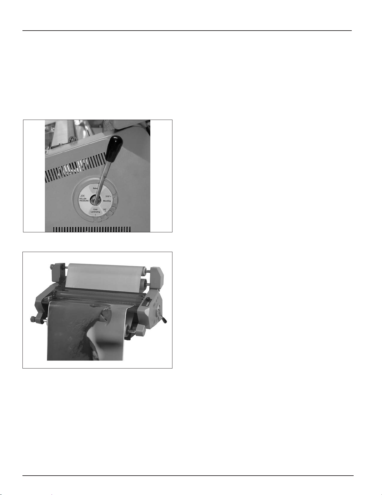
ROLLER PRESSURE HANDLE
BOTTOM FILM SUPPLY SHAFT
Holds the film or kraft paper on the machine.
FILM WEB
(Not shown.) The path the laminating film and/or
mounting film mounted on the machine takes
through the machine.
Page 5-2
Roller pressure
handle
Settings
Fig. 5-4. Roller Pressure Handle.
The roller pressure handle adjusts the amount of
roller pressure needed for various laminating and
mounting applications. Pull the handle out of a
position, rotate it to the desired pressure, and press
it into the slot. Three main function settings are
provided.
Page 15

Operating Instructions
RUN
STOP
REVERSE
min. max.
27C
IMPORTANT: Use a pressure setting that is
appropriate for the material you are laminating or
mounting.
Release – Provides the widest opening between the
pressure rollers and takes pressure off the rollers.
This is used when installing new rolls of film. When
the machine is not in use, put the handle in this
position.
Mounting – Used when bonding to a rigid substrate
such as mounting boards. Thickness range is 1/8 to
3/16 in. (3.2 to 4.8 mm).
Laminating – Used to adhere materials in multiple
substrates. The two positions are low (right) and high
(left) pressure.
FILM AND TAKE-UP TENSION ADJUSTMENT
K
NOBS
Tension adjustment
knobs
CONTROL PANEL
Speed
adjustment
RUN
button
LED
Fig. 5-6. Control Panel.
Speed adjustment – Turn the speed adjustment
knob to set the desired speed. It is adjustable from
2.5 (min.) to 15 (max.) feet per minute (fpm) (0.8 to 4
m).
STOP
button
REVERSE
button
Fig. 5-5. Tension Adjustment Knobs.
Allows the operator to increase or decrease film web
and release liner tension as needed to reduce curl
and wrinkles.
RUN button – Press and release the RUN button for
continuous running. The green LED illuminates. For
normal operation, the safety shield must be installed.
WARNING: Keep your fingers and hands
away from the nip point (the point where the upper
and lower rollers meet). Failure to observe this
warning could result in severe personal injury.
STOP button – Press the STOP button to stop the
machine.
REVERSE button – Press and hold the REVERSE
button to reverse the direction of the rollers. Release
the button to stop. The green LED illuminates while
the button is pressed.
Page 5-3
Page 16

27C
POWER SWITCH
The power switch is located at the back of the
machine. Press the “I” on the switch to turn it on. An
orange LED will illuminate next to the stop button.
The off position, marked “0”, turns the machine off.
Operating Instructions
Page 5-4
Page 17

Operating Instructions
RUN
STOP
REVERSE
min. max.
6. OPERATION
27C
This chapter describes how to use the laminator to:
Operate the machine
•
Load films (web the machine)
•
Laminate items
•
Mount items
•
GENERAL OPERATION
These instructions assume that the films have been
loaded. For information about loading films, see the
Loading Film section in this chapter.
Speed
adjustment
Set the roller pressure handle for the thickness of
2.
the item that is to be laminated or mounted.
Fig. 6-2. Roller Pressure Handle.
Set the desired speed on the control panel.
3.
Press the RUN button.
4.
The rollers will begin to turn.
RUN
button
LED
Fig. 6-1. Control Panel.
STOP
button
REVERSE
button
To run the laminator:
Turn the laminator On (I) with the power switch
1.
located at the back of the machine.
WARNING: Make sure the safety shield and
feed tray are in their proper positions. Your fingers
and hands could be trapped and crushed in the
rollers. Clothing, jewelry, and long hair could be
caught in the rollers and pull you into them.
Position the item(s) to be laminated or mounted
5.
on the feed table.
Push the item(s) squarely into the roller nip point
6.
(where the two rollers meet). Additional items
can be laminated or mounted without stopping
and starting the machine.
Press the STOP button to stop the laminator
7.
when all of the items have completely exited the
rear of the machine.
Page 6-1
Page 18

27C
Operating Instructions
LOADING FILM
The 27C laminator runs poly-in and poly-out
pressure sensitive adhesive (PSA) films. Poly-in
means the adhesive side of the film is on the inside
of the web. Poly-out means the adhesive is on the
outside of the web.
The machine can perform three functions:
Decaling (laminating and applying an adhesive
•
to the back of the item).
Mounting, using one film.
•
Mounting, using no film.
•
Poly-in
IMPORTANT: The top and bottom rolls of laminating
film must be the same width.
Always change the top and bottom supply rolls at
the same time. Near the end of each roll of most
laminating film is a label stating, Warning – End
of Roll. The appearance of this label on either the
top or bottom roll requires that new rolls of film
be installed as soon as the item presently being
laminated completely exits the rear of the laminator.
Do not introduce any additional items into the
laminator when the warning label is visible.
Adhesive will deposit on the rollers if:
One or both rolls of film are allowed to run
•
completely off its core.
Only one roll is used.
•
Different widths of rolls are loaded together.
•
Either roll is loaded with the adhesive side
•
against a roller.
Adhesive surface
Poly-out
Adhesive surface
Fig. 6-3. Poly-in and Poly-out Films.
Polyester surface
Polyester surface
There are two methods of loading film.
Using a threading card.
•
Tacking new film to existing film.
•
Prior to loading film, the safety shield and feed table
need to be removed.
Page 6-2
Page 19

Operating Instructions
27C
REMOVING AND INSTALLING THE SAFETY
S
HIELD
The safety shield should not be removed except to
install films and when cleaning the rollers. When the
shield is off, the laminator runs at a fixed speed of 3
fpm (0.9 m).
WARNING: Keep fingers and hands away from
the rollers when the machine is running. They could
be trapped and crushed in the rollers. Clothing,
jewelry, and long hair could be caught in the rollers
and pull you into them.
Safety shield
Feed table
Interlock latch
(under table)
REMOVING AND INSTALLING THE FEED
T
ABLE
The feed table should not be removed except to
install films. When the table is off, the laminator runs
at a fixed speed of 3 fpm (0.9 m). Refer to Fig. 6-4 for
the following instructions.
To remove the feed table :
Slide the feed table latch to the right.
1.
Lift the table upwards and away from the
2.
laminator.
To install the feed table:
Place the table on the machine.
1.
Slide the feed table latch to the left.
2.
Fig. 6-4. Safety Shield and Feed Table.
To remove the shield:
Lift the front edge of the shield.
1.
Lift and slide the back of the shield towards the
2.
back of the machine and lift the shield off.
To install the shield:
Place the pins at the back of the shield in the
1.
slots on the machine.
Lower the front edge of the shield, making sure
2.
that the front guides engage the safety switches.
Page 6-3
Page 20
27C
Operating Instructions
LOADING FILM ONTO THE SUPPLY SHAFTS
If you are replacing existing films, perform the
following first set of instructions,
films
. If you are loading film for the first time,
skip these instructions and start with the next
instructions,
To load films
Fig. 6-5. Roller Pressure Handle.
.
To remove existing
To remove existing films:
Put the roller pressure handle to Release.
1.
Cut the remaining top and bottom films just
2.
ahead of the pressure rollers. Do not allow the
remaining film to pass through the laminator
if there is any exposed adhesive. Pull the
remaining film out the front of the machine.
CAUTION: Be careful to not cut the pressure rollers.
Failure to observe this notice can result in damage to
the rollers.
Remove the release liner from the take-up core
3.
by doing the following.
Grasp the take-up shaft and push it to
a.
the left and lift the right end upward and
out of the support.
Unwind or cut the liner from the core. Do
b.
not damage or throw away the core.
Fig. 6-6. Release Liner Take-up and Supply Films on the
Machine.
Put the shaft, with the core, back on the
c.
machine by inserting the left end (hex
end) in the left side of the drive and, while
pushing to the left, lower the bearing into
the right side of the machine.
To remove the film core shaft, grasp the supply
4.
shaft, press it to the right until the left end of the
hex shaft clears the brake hub, and raise the left
end of the shaft out of the machine. Do this for
the top and bottom supply shafts.
Slide the core off the shaft and core adaptors.
5.
Tip: Twist the shaft while pulling to remove the
core easier.
Clean the pressure rollers if needed. See the
6.
Operator Maintenance
chapter in this manual.
Page 6-4
Page 21

Operating Instructions
27C
To load films onto the supply shafts:
If the supply shaft is on the machine, remove it
1.
by grasping it, pressing it to the right until the left
end of the hex shaft clears the brake hub, and lift
the left end out of the machine. This applies to
the top and bottom supply shafts.
Slide the new roll on to the shaft and core
2.
adaptors, referring to Fig. 6-3. to determine how
the film unwinds from the roll. Use the set screws
in the core adaptors to move the adaptors if
needed. The grippers on the core adaptors
should be pointing in the opposite direction that
the film unwinds from the roll.
Take-up shaft
Core adaptor
Supply shaft
Gripper
Insert the bearing end of the shaft into its
3.
support on the right side of the machine, press
to the right, and then insert the left end of the
hex shaft into the brake hub.
Center each supply roll on the shafts by doing
4.
the following.
Use a ruler to measure from the left edge of
a.
the roll to the left side frame.
Do the same on the right side.
b.
Shift the roll side to side so that both
c.
measurements are equal. It is important that
the edges of the films are aligned so that
adhesive does not get on the rollers.
Center the take-up core on its shaft.
5.
Fig. 6-7. Core Adaptors on the Shafts.
Gripper
Fig. 6-8. Direction of Core Adaptor Gripper on Poly-in Film.
Fig. 6-9. Films Loaded on the Laminator.
Page 6-5
Page 22

27C
LOADING FILM WITH A
T
HREADING CARD
The following procedure uses a film threading card
that is sometimes provided with new rolls of film. If
one is not provided, a scrap piece of cardboard or
poster board with a straight edge is suitable. Either
can be reused. Prior to loading film, remove the
safety shield and feed table.
Note: These instructions are for loading laminating
and mounting films for decaling. The top supply
shaft is used for laminating films and the bottom
supply shaft is used for mounting film or kraft paper.
If you are not applying mounting film to a laminate,
kraft paper should be used on the bottom supply
shaft to prevent adhesive from sticking to the rollers.
For more information about loading films for other
processes, refer to the appropriate section in this
chapter.
Operating Instructions
Fig. 6-10. Top Film Draped Over the Pressure Rollers and
Release Liner Attached to Take-up.
Pull the mounting film (or kraft paper) up to
6.
about even with the top of the top pressure roller
without touching the sticky laminating film.
To web (load the films) the machine:
Remove the safety shield and feed tray. Refer
1.
to
Safety Shield Removal and Installation
Table Removal and Installation
Pull the top film down, thread it under the idler
2.
bar, and pull the film back up to the take-up core.
Lightly tape both corners of the film to the take-
3.
up core.
Ensure that the film is pulled evenly and that no
bulges exist at either end of the idler bar.
Using a very sharp utility knife, lightly score the
4.
laminating film approximately 4 in (10 cm) above
the upper pressure roller.
Be careful to not cut through the release liner.
Pull the laminating film away from the liner and
5.
drape it over the front of the pressure rollers so
that it extends to a little past the bottom of the
top pressure roller.
in this section.
and
Feed
While pulling evenly, carefully align the edges of
7.
the mounting film with the laminating film, and
press the two together. It is important that the
tension is even from one end of the supply rolls
to the other.
Fig. 6-11. Bottom Film Stuck to Top Film.
Press the straight edge of the threading card into
8.
the two films at the nip (the point between the
two pressure rollers) until the card and films are
slightly past the nip.
Page 6-6
Page 23

Operating Instructions
Fig. 6-12. Threading Card Inserted Between Films.
27C
LOADING FILM BY TACKING NEW FILM TO
E
XISTING FILM
The following describes a method for loading film
whereby the existing film on the rollers may be used
in place of the threading card to draw the new film
through the laminator. Leading edges of the new
film will be overlapped onto the adhesive of the old
film. The existing film and the new film will be pulled
through the laminator together.
Remove the safety shield and feed tray. Refer
1.
to
Safety Shield Removal and Installation
Table Removal and Installation
in this section.
and
Feed
Move the roller pressure handle to where it
9.
applies pressure to the threading card.
Press the RUN button on the control panel and
10.
guide the threading card into the machine until
the rollers pull the card on its own.
WARNING: Keep your fingers and hands away
from the nip point while the machine is running.
They could be trapped and crushed in the rollers.
Clothing, jewelry, and long hair could be caught in
the rollers and pull you into them.
Release the card and ensure that both films and
11.
card are being pulled into the laminator.
The card will guide the film webs into the rollers.
Replace the safety shield and feed table.
12.
Refer to Safety
Feed Table Removal and Installation
Check the film alignment and adjust the tension
13.
if needed.
See the
Film Alignment
Shield Removal and Installation
section in this chapter.
in this section.
and
Cut remaining bottom film web between the
2.
supply roll and rollers.
Remove the existing bottom supply roll and
3.
replace with new film. Refer to the
Onto the Supply Shafts
Unroll enough film from the bottom roll of film
4.
to tack to the existing bottom film. Make sure
to carefully align the edges of the films before
tacking them together.
Cut remaining top film web between the supply
5.
roll and rollers. Do not allow the adhesive to stick
to the rollers or the bottom film.
Remove the existing top supply roll and replace
6.
with new film.
Unroll enough film from the top supply roll
7.
shaft to tack to the existing top film. Make sure
to carefully align the edges of the films before
tacking them together.
section in this chapter.
Loading Film
Page 6-7
Page 24

27C
Operating Instructions
DECALING IN TWO PASSES
Decaling is where you laminate items and then
mount them on other materials such as Foam Core
or mounting board. It is performed in two passes.
The first pass laminates and applies the mounting
adhesive, encapsulating the item. The second pass
mounts it on rigid material.
This two pass operation requires pressure sensitive
laminating film on the top supply shaft and pressure
sensitive mounting film on the bottom supply shaft.
Refer to Fig. 6-15 for the proper configuration of
Poly-in or Poly-out film.
Fig. 6-13. New Films Tacked to Old Films.
Install the feed table and safety shield.
8.
Set the speed for the slowest speed setting and
9.
press RUN
Watch the film being pulled through the laminator
10.
to ensure that the remaining existing film and the
new film are advancing concurrently and evenly.
Any separation between the films will require
stopping the motor immediately and the situation
corrected.
Press STOP once the newly threaded film
11.
completely exits the laminator.
Check the film alignment and adjust the tension
12.
if needed.
See the
.
Film Alignment
section in this chapter.
Take-up
PSA Film
Release liner
PSA mounting film
Fig. 6-14. Laminator Loaded for Decaling the First Pass
with Film (Poly-in Shown).
Poly-in
Poly-out
Page 6-8
Fig. 6-15. Configurations for Poly-in and Poly-out Films.
Page 25

Operating Instructions
27C
To run the first pass:
Load the laminator as shown in Fig. 16.
1.
Adjust the roller pressure handle to the proper
2.
laminating setting.
Place the item to be laminated on the feed table,
3.
then press RUN
Guide the item into the rollers.
4.
Once the item has cleared the back of the
5.
machine, press STOP
Remove the web and trim out the encapsulated
6.
item.
To run the second pass:
Unweb (unload the films) the laminator before
running the second pass.
.
.
Butt the leading edge of the board up against the
6.
rollers.
Drape the encapsulated item over the safety
7.
shield.
Do not allow the print to flop backwards.
Press RUN and immediately grasp the release
8.
liner for separation as the board is pulled into the
rollers. Do not allow the release liner to be pulled
into the rollers.
After the board has cleared the rollers press
9.
STOP
.
Print over safety shield
Release liner
Fig. 6-16. Laminator Ready for Mounting.
Adjust the roller pressure handle to the proper
1.
mounting setting.
Set the motor speed to min.
2.
Peel back the leading edge of the release liner
3.
of the laminated item approximately 4 inches (10
cm).
Place the item on the mount board.
4.
Tack the exposed adhesive edge of the item,
5.
from the center out, to the leading edge of the
board.
Be sure to not introduce wrinkles or air bubbles.
Page 6-9
Page 26

27C
Operating Instructions
MOUNTING
TIPS FOR THREADING PRESSURE
S
ENSITIVE ADHESIVE (PSA) FILM
Use kraft paper for one-sided lamination.
•
Refer to
•
configuration.
Whenever possible, pull the remaining web
•
of film out the front of the laminator after the
finished item has been removed.
PRE-TREATING BOARDS
You may wish to pre-coat mounting boards ahead of
time with PSA mounting film.
Fig. 6-15.
for the proper film
PSA mounting film
MOUNTING ONLY
This process requires a decalled item with PSA
mounting adhesive. Refer to the
pass instructions
of this chapter. An alternative method is to use a
PSA pre-treated board, which is described in the
Mounting and Overlamination
in the
Decaling In Two Passes
To run the second
section
section.
FILM ALIGNMENT AND TENSION
FILM ALIGNMENT
The top and bottom supply rolls must be aligned
as closely as possible. Misalignment can cause
adhesives to be deposited on the rollers.
Measure here
Board
Fig. 6-17. Laminator Ready for Pre-treating Boards.
To pre-treat boards:
Load the laminator as shown in Fig 5-17.
1.
Adjust the roller pressure handle to the proper
2.
mounting setting.
Start a leader board into the rollers.
3.
Press RUN
4.
Continue feeding one board after another.
5.
Tip: Butt the leading edge of the next board to
the trailing edge of the previous one to ensure an
even application of film.
.
Fig. 6-18. Measuring Points.
To align the supply rolls:
Use a ruler to measure the distance between the
1.
left edge of the roll to the side frame.
Measure the distance between the right side of
2.
the roll to the side frame.
Shift the roll side to side to ensue that the two
3.
measurements are equal.
Press STOP when the last board exits the
6.
machine.
Page 6-10
Page 27

Operating Instructions
FILM TENSION
27C
Proper film tension, known as brake tension, is the
minimum amount required to eliminate wrinkles in the
finished item. Tension adjustments are not necessary
if you are using 1.5 or 3 mil (38 or 75 mic) film unless
the lamination is curling up or down. Generally, 5 and
10 mil (125 and 250 mic) films require more tension.
As the film roll becomes smaller, tension increases,
thus the adjustment needs to be loosened. Film
tension should be checked occasionally to assure
that the adjustment is correct.
The film should be taut with no gaps between the
film and pressure rollers. A properly adjusted roll
of film should not require excessive force to turn by
hand. Film tension should be enough to introduce a
minor amount of drag as the film unrolls. Insufficient
tension causes wrinkles, while too much tension
causes stretching (necking). Uneven tension
between the top and bottom rolls create curl. Too
much upper tension creates upward curl. Too much
lower tension bottom causes downward curl.
Tension adjustment
knobs
Fig. 6-19. Tension Adjustment Knobs.
The machine is equipped with external tension knobs
located on the left side. Turning the knobs clockwise
increases the tension while counterclockwise
decreases the tension.
Testing the Web
After webbing the machine, it is important that the
films run straight and evenly.
To test the web:
Set the roller pressure handle to an appropriate
1.
position.
Press the RUN button and run approximately
2.
6 in. (10 cm) of laminate.
Press the STOP button.
3.
Visually inspect the top and bottom films where
4.
they enter the nip.
The films should be tight against the rollers
at both ends. If they are not, use the tension
adjustment knobs to tighten the loose supply film
brake and run another test.
Ensure that the release liner take-up is keeping
5.
the liner tight against the idler bar.
If it is loose, use the tension adjustment knob to
increase the tension.
Run test materials before laminating good
6.
materials.
Page 6-11
Page 28

27C
Operating Instructions
CLEARING A FILM JAM (WRAP-UP)
Film jams (wrap-ups) may occur if the film is loaded
backwards or if the area at which film exits the
equipment is blocked. The film, when jammed, wraps
around the rollers. Jams also occur if something is
too large to pass through the rollers.
Determine the best course of action to clear the
jam. It may be necessary to rotate the rollers in the
reverse direction. Set the speed to min. Press and
hold the REVERSE button on the control panel.
CAUTION: Be careful to not cut the pressure rollers
when cutting the film. Failure to observe this notice
can result in damage to the rollers.
To clear a jam:
Immediately press the STOP button to stop the
1.
machine.
Remove the safety shield and feed tray.
2.
Do one of the following.
3.
Pull one of the webs while running the
a.
laminator in reverse.
Cut the film near the rollers, set the
b.
pressure adjustment to Release, and pull
the film out the back of the machine.
Cut the film near the rollers, set the
c.
pressure adjustment to Release, grasp
the loose ends of the web, and pull
straight out the front of the machine.
Replace the safety shield and feed tray.
4.
Re-load the film if necessary. See the
5.
Film
section in this chapter.
Loading
LAMINATION GUIDE
Do not attempt to laminate abrasive or metal objects
such as staples, paper clips and glitter, as they may
damage the rollers.
Do not force items into the nip area of the rollers. An
item that is not easily drawn into the laminator by the
rollers is probably too thick to laminate.
Wrinkles may result if an attempt is made to
reposition an item once it has been grasped by the
rollers.
Do not stop the laminator before an item has
completely exited the pull rollers. Even a momentary
stop may cause a mark on the laminated item.
Good, consistent lamination is a result of combining
proper tension and dwell time. Dwell time is
controlled by the speed of the motor and is defined
as the amount of time the material to be laminated is
compressed between the rollers.
As a general rule, thicker items and film need to run
at slower speeds. Setting the speed control at slower
settings gives the laminator longer dwell time thus
allowing proper lamination of thick items. Thinner
items, such as standard copier paper (20 Ib. bond)
and tissue paper can be run at faster speeds.
Do not combine thick and thin items at the same
time, as this will result in a poor edge seal around
the thinner material. If you are unsure that the
laminator is set at the proper speed for the item to
be laminated, run a test piece (scrap) of the same or
similar material through the laminator. Make speed
adjustments if necessary.
This manual provides general guidelines and is only
a general reference guide. Different settings may be
suitable as the lamination time and materials change.
Test materials before running good materials through
the machine.
Page 6-12
Page 29

Operating Instructions
7. OPERATOR MAINTENANCE
27C
CARING FOR THE 27C LAMINATOR
The only maintenance required by the operator
is to periodically clean the rollers. The following
procedure will help keep them free of dirt and
adhesive, which has been deposited along the edge
of the laminating film. Proper alignment of the rolls of
film reduces the amount of adhesive on the rollers.
Perform only the routine maintenance procedures
referred to in these instructions.
WARNINGS:
Do not attempt to service or repair the laminator.
•
Do not apply any cleaning fluids or solvents to the
•
rollers. Some solvents and fluids could damage
the rollers.
Keep fingers and hands away from the rollers
•
when the machine is running. They could be
trapped and crushed in the rollers. Clothing,
jewelry, and long hair could be caught in the
rollers and pull you into them.
Failure to observe these warnings could result in
severe personal injury or death or damage the
machine.
To clean the rollers and idler bar:
Remove the safety shield and feed table. Refer
1.
to
Removing and Installing the Safety Shield
Removing and Installing the Feed Table
Operation
Remove the film from the laminator. Refer
2.
to
Loading Film Onto the Supply Shafts
Operation
Gently rub the top and bottom rollers with a
3.
3M Scotch-Brite pad. DO NOT USE METAL
SCOURING PADS! Do not use any abrasives to
clean the rollers.
Use the dampened rag to remove any dust, dirt,
4.
and other foreign materials from the rollers.
Press and release the RUN button to rotate the
5.
rollers to an unclean portion.
Keep your hands, fingers, pad, and rag away
while running the machine. Be sure to remove all
adhesive and dirt.
Install the feed table and safety shield.
6.
chapter.
chapter.
in the
in the
and
CLEANING THE ROLLERS
Keeping the rollers clean ensures that your finished
items will not be damaged by dirt and adhesives.
You will a 3M™ Scotch-Brite™ pad and a clean rag
moistened with water and dish soap.
Never clean rollers with abrasive, sharp, or
•
pointed objects.
Do not use any other cleaning agents other
•
than those listed above.
Accumulated adhesive deposits on the rollers
•
can cause damage to the rollers. Rotate the
rollers at the lowest speed setting on the
control panel.
Page 7-1
Page 30

27C
TROUBLESHOOTING
Symptom Possible Cause Corrective Action
Operating Instructions
Power lamp does not
illuminate (next to the stop
button when the
ON/OFF switch is in the
ON position.
Rollers do not turn. Safety shield not seated properly. Lower safety shield.
Laminated items are
curling.
Adhesive deposited on
rollers.
Laminator not connected to electrical
supply.
Fuse blown out. Replace fuse or contact your dealer/
Feed tray interlock latch not in place. Slide interlock latch all the way to the left
Tension between the top and bottom film
roll is unequal.
Tension on top or bottom roll of film is too
loose.
Grippers on core adaptors pointing in the
wrong direction.
Speed setting too slow. Slightly speed up laminator.
Top and bottom film webs not aligned. Align film webs per
Laminate improperly loaded. Load film per
Insert attachment plug into receptacle.
distributor for assistance.
into the side frame.
Adjust tension per
Adjust tension per
Load film per
Shafts
section.
Loading Film Onto the Supply
Loading Film
Film Tension
Film Tension
Film Alignment
section.
section.
section.
section.
Unsatisfactory laminate
adhesion.
Speed setting too fast for type of material
being laminated.
Laminate improperly loaded. Load film per procedure outlined per
Rollers require cleaning. Clean rollers per
Laminated item unsuitable for adhesion. Item may be dirty or may have non-
Lower speed setting by turning the speed
knob to slower Speed.
Loading Film
section.
porous surface that is extremely difficult
to laminate.
section
Cleaning the Rollers
Page 7-2
Page 31

Operating Instructions
27C
Page 7-3
Page 32

 Loading...