

Page 1
© 2002 IBICO. ALL RIGHTS RESERVED.
Do not duplicate without written permission.
Part number : 930 - 076B
Page 2

The information in this publication is provided for reference and is believed to be
accurate and complete. Ibico is not liable for errors in this publication or for incidental or
consequential damage in connection with the furnishing or use of the information in this
publication, including, but not limited to, any implied warranty of fitness or
merchantability for any particular use.
Ibico reserves the right to make changes to this publication and to the products
described in it without notice. All specifications and information concerning products are
subject to change without notice.
Reference in this publication to information or products protected by copyright or
patent does not convey any license under the rights of Ibico or others. Ibico assumes no
liability arising from infringements of patents or any other rights of third parties.
This publication is copyrighted © 2002 by Ibico. All rights reserved. The
information contained in this publication is proprietary and may not be reproduced,
stored, transmitted, or transferred, in whole or in part, in any form without the prior and
express written permission of Ibico. Ibico a company of GBC.
Page 3

Operations Manual Patriot 25E
Table of contents
1.0 Safety
1.1 Explanation of symbols 1-1
1.2 General Rules of safety 1-1
1.3 Labels 1-2
Figure 1.3.1 Safety label placement 1-3
2.0 Warranty
2.1 Limited warranty 2.1
2.2 Exclusions to the warranty 2-1
3.0 Specifications
3.1 Film capacity 3-1
3.2 Operating speed 3-1
3.3 Weight 3-1
3.4 Electrical requirements 3-1
3.5 Dimensions 3-1
Figure 3.5.1 Patriot 25E 3-2
4.0 Installation
4.1 Setting up the laminator 4-1
4.2 Know your laminator 4-2
5.0 Operations
5.1 Components on the laminator 5-1
5.2 Control panel 5-3
Figure 5.2.1 Control panel 5-3
5.3 Feed table 5-4
5.4 Supply shaft 5-4
5.5 Film alignment 5-4
5.6 Adjusting film tension 5-5
6.0 Applications
6.1 Film loading and threading 6-1
6.2 Starting an application 6-2
6.3 Speed guide 6-4
Figure 6.3.1 Speed guide 6-4
6.4 Helpful hints 6-5
6.5 Important points to remember 6-5
7.0 Maintenance and troubleshooting
7.1 Cabinets, cover and stand 7-1
7.2 Clean the rollers 7-1
7.3 T roubleshooting 7-2
Figure 7.3.1 T roubleshooting guide 7-3
Page I © 2002 IBICO
Page 4

8.0 Recommended spares
8.1 Spare parts list 8-1
9.0 Illustrated parts
9.1 Parts list 9-1
9.2 Illustrations 9-4
P25E-001 Slitter assembly 9-4
P25E-002 Covers and table assembly 9-5
P25E-003Control panel assembly 9-6
P25E-004 Cover and film shaft assembly 9-7
P25E-005 Frame assembly 9-8
P25E-006 Control side assembly 9-9
P25E-007 Rollers and heater assembly 9-10
P25E-008 Drive side assembly 9-1 1
P25E-009 Latch assembly 9-12
P25E-010 Electrical Schematic 9-13
Operations ManualPatriot 25E
Page II © 2002 IBICO
Page 5

Operations Manual Patriot 25E
1.0 Safety
ELECTRICAL HAZARD: [This symbol is used prior
to a step. The information following this symbol is
CAUTION: Do not attempt to operate your Patriot
25E Laminator until you completely read and
understand this Operations Manual.
to prevent an electrical shock condition that may be
caused by an operators action or machine function.]
Your safety, as well as the safety of others, is important to
Ibico. This section contains important safety information
which must be adhered to while operating, cleaning and
performing basic maintenance in and around the machine.
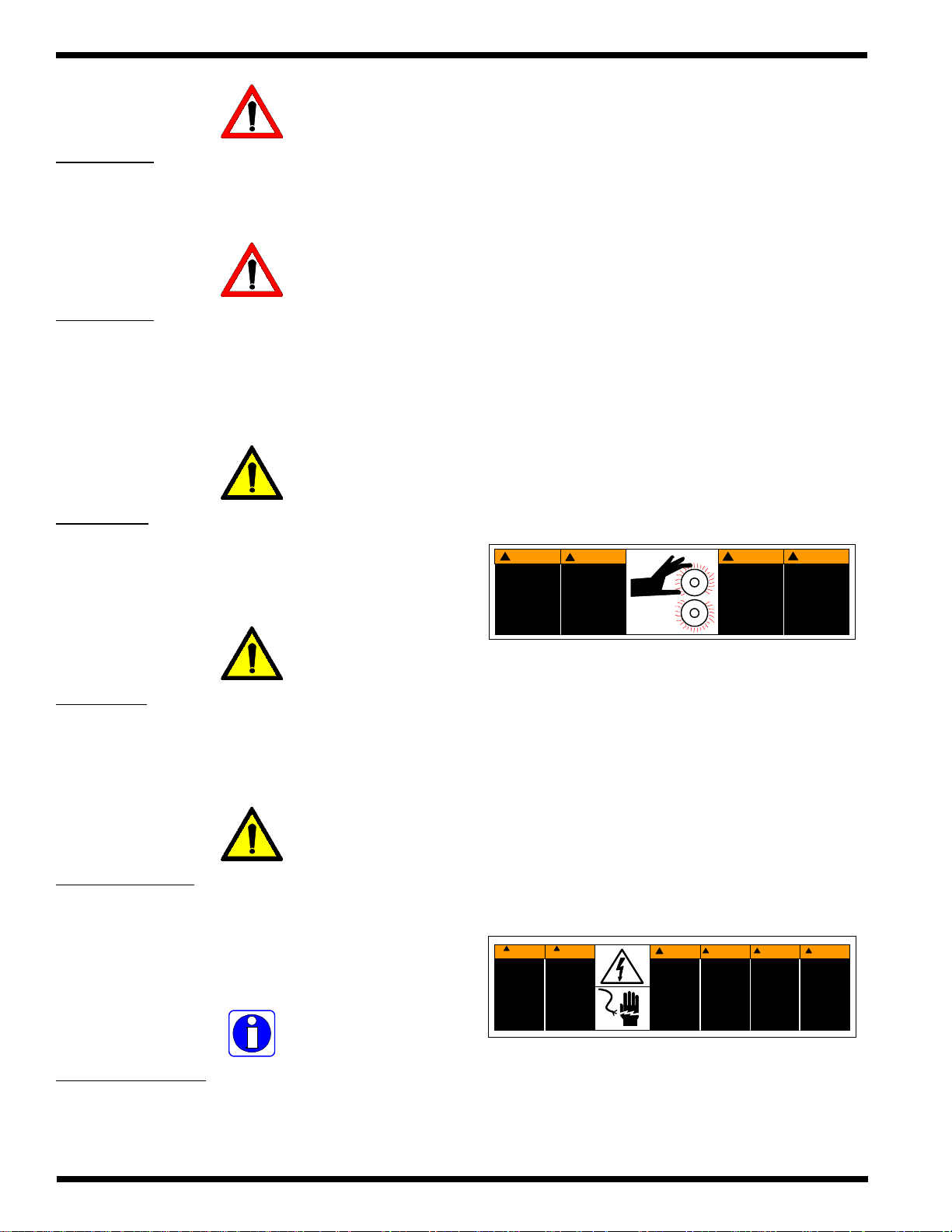
1.1 Explanation of symbols
INFORMATION: [This symbol is used prior to,
during and/ or after a step. Following this symbol is
important information pertaining to current
subject.]
1.2 General rules of safety
ELECTRICAL HAZARD: Do not operate the
laminator if power cord is damaged or frayed. Y ou
can be severely shocked, electrocuted or cause a
fire.
WARNING: Do not operate this laminator if you
are not physically , psychologically or emotionally fit.
Do not operate this machine until you have been
trained and read this manual in it’ s entirety .
CAUTION: [This symbol is used prior to a step. The
information following this symbol is to inform you
of how to avoid harm to you, others around you or
to the equipment.]
WARNING: [This symbol is used prior to a step.
The information following this symbol is to inform
you of how to avoid a dangerous situation.]
WARNING: Do not wear ties, loose fitting clothes
or dangling jewelry while operating or servicing the
laminator . These items can get caught in the nip and
choke you or you can be crushed or burned.
WARNING: Never tamper with the safety devices
to increase the laminator’s production capacity . In
the event a safety device should fail, never attempt
to bypass it for operation. Consult a service
representative immediately .
© 2002 IBICO Page 1-1
Page 6
Patriot 25E
Operations Manual
1.3 Labels
WARNING: Never use this machine for any other
purpose than its intended design and function.
WARNING: Do not make any modifications to this
laminator. Unauthorized changes will void your
warranty and may cause extensive repairs or create
poor output quality.
CAUTION: Only use acceptable materials through
this laminator. Unacceptable materials may cause
damage to the rollers or cause poor output quality .
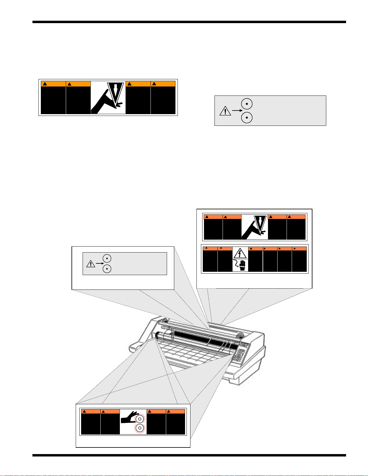
Refer to Figure 1.3.1 Label locations
Safety warning labels are placed at various locations on
the laminator. Do not remove any of these labels. They
are place for your safety as well as the safety of those
working around you.
Below are illustrations of the safety labels and a
description of thier meanings.
Hot rollers
– The safety label below means that you could be burned
and your fingers and hands could be trapped and crushed
in the heat rollers. Jewelry and long hair could be caught
in the rollers and you could be pulled into them.
!
CUIDADO
RODILLOS
CALIENTES.
PUNTO DE
PINCHAMIENTO.
Mantener m anos y
ropa a dis tancia.
!
ATTENTION
ROULEAUX
CHAUDS.
POINT DE
PINCEMENT.
Tenir mains et
vetements a l'ecant.
CAUTION
!
HOT ROLLS.
PINCH POINT.
Keep hands and
clothi ng away.
WARNUNG
!
HEISSE
ROLLEN
Klemmgef ahr
zwischen Rollen
Hande und
Kleidung ferhalten
CAUTION: Exercise extreme caution when working
around or replacing the film cutter blade. This blade
is sharp and cut you.
INFORMA TION: Always observe all warning labels
placed at various points on the laminator . If you do
not completely understand a label, contact your local
service representative for further explanation.
INFORMATION: Any concerns for safety or
operation should be brought to the attention of your
local service representative immediately .
One label is placed on each side from the front operating
position just in front of the heat rollers nip.
Electrical hazard
– The safety label below means that you could be seriously
hurt or killed if you open the product and expose yourself
to hazardous voltage.
!
Riesgo de
choque
electrico
No abra
Adentro, no hay
piezas
reparables
para el usuario.
Mantenimiento
solamente para
personal
calificado
This label is located on the rear panel in the center of the
laminator just below the rear slitter.
MUCHO
CUIDADO
!
MUCHO
CUIDADO
Risque de
secousse
electrique.
Ne pas ouvrir.
Pas de pieces
reparables par
l'utilisateur.
Entretien par
personnel
qualifie.
WARNING!WAARSCHUWING!ATTENZIONE!WARNUNG
Electrical shock
hazard.
Do not open.
No user
serviceable
parts inside.
Refer servicing to
qualified service
personnel.
Kans op
elektrische
schok.
Niet openen
Bevatgeen door
gebruik te
repareren
onderdelen.
Door bevoegd
service personeel
laten repareren
Pericolo di
scarica
elettrica.
Nessuna parte
riparabile
dall' utente.
Chiamare un
servizio
di riparazioni
qualificato.
!
SpannungsfUhr end
e
Teile.
Nicht offnen.
Enthalt keine vom
Enduerbrauc her zu
wartende Tei le.
Fur service bitte an
qualifizier tes
Service-Personal
wenden.
© 2002 IBICOPage 1-2
Page 7
Operations Manual Patriot 25E
Sharp knife
– The safety label below means that you could cut yourself
if you are not careful.
!
CUIDADO
NAVAJA FILOSA.
Mantener m anos y
dedos a distancia.
!
ATTENTION
LAME COUPANTE.
Tenir mains et
doigts a l'ecant.
CAUTION!WARNUNG
SHARP BLADE.
Keep hands and
clothi ng away.
!
SCHAREE KLINGE
Hande und finger
ferhalten.
This label is located on the rear panel in the center of the
laminator just above the Electrical hazard safety label and
below the rear slitter.
Figure 1.3.1 Safety label placement
Pinch point
– The safety label below means use extreme caution when
placing your hands in the proximity of the pull rollers nip.
You should never place your fingers or other items in this
area while the machine is running.
Use caution in proximity of
pull rollers.
This label is located between the pull rollers and the rear
slitter guide center of the rollers.
Use caution in proximity of
pull rollers.
(1) Between pull rollers and slitter guide
!
CUIDADO
NAVAJA F ILOSA.
Mantener manos y
dedos a distancia.
!
MUCHO
CUIDADO
Riesgo de
choque
electrico
No abra
Adentro, no hay
piezas
reparables
para el usuario.
Mantenimiento
solament e para
personal
calificado
LAME COUPANTE.
Tenir mains et
doigts a l'ec ant.
!
MUCHO
CUIDADO
Risque de
secousse
electrique.
Ne pas ouvrir.
Pas de pieces
reparables par
l'utilisateur.
Entretien pa r
personnel
qualifie.
!
ATTENTION
SHARP BLADE.
Keep hands and
clothing away.
WARNING!WAARSCHUWING!ATTENZIONE!WARNUNG
Kans op
Electrical shock
elektrische
hazard.
schok.
Do not open.
Niet openen
No user
Bevatgeen door
serviceable
gebruik te
parts inside.
repareren
Refer servicing to
onderdelen.
qualified service
Door bevoegd
personnel.
service personeel
laten repareren
!
CAUTION!WARNUNG
SCHAREE KLINGE
Hande und finger
ferhalten.
!
Pericolo di
SpannungsfUhrend
e
scarica
elettrica.
Teile.
Nessuna parte
Nicht offnen.
riparabile
Enthalt keine vom
dall' utente.
Enduerbraucher zu
Chiamare un
wartende Te ile.
servizio
Fur service bitte an
di riparazioni
qualifizierte s
qualificato.
Service-P erson al
wenden .
(1 ea.) Center rear panel below pull rollers
CAUTION!WARNUNG
!
CUIDADO
RODILLOS
CALIENTES.
PUNTO DE
PINCHAMIENTO.
Mantener manos y
ropa a dist ancia.
!
ATTENTION
ROULEAUX
CHAUDS.
POINT DE
PINCEMENT .
Tenir mains et
vetements a l'ecant .
HOT ROLLS.
PINCH POINT.
Keep hands and
clothing away.
!
HEISSE
ROLLEN
Klemmgefahr
zwischen R ollen
Hande und
Kleidung ferhalten
(2) One on each side of the laminator
© 2002 IBICO Page 1-3
Page 8

Patriot 25E
This page intentionally left blank.
Operations Manual
© 2002 IBICOPage 1-4
Page 9

Operations Manual Patriot 25E
2.0 Warranty
IBICO warrants the equipment to be free from defects in
material and workmanship for a period of 90 days for
parts and labor from the date of installation. This warranty
is the only warranty made by IBICO and cannot be
modified or amended.
IBICO’s sole and exclusive liability and the
customer’s sole and exclusive remedy under this
warranty shall be, at IBICO’s option, to r epair or
replace any such defective part or product. These
remedies are only available if IBICO’s examination
of the product discloses to IBICO’s satisfaction that
such defects actually exist and were not caused by
misuse, neglect, attempt to repair, unauthorized
alteration or modification, incorrect line voltage, fire,
accident, flood or other hazard.
DAMAGE OR PERSONAL INJURY (UNLESS
PRIMARIL Y CAUSED BY ITS NEGLIGENCE),
LOSS OF PROFIT OR OTHER INCIDENT AL OR
CONSEQUENTIAL DAMAGES ARISING OUT
OF THE USE OR INABILITY TO USE THE
EQUIPMENT.
2.2 Exclusions to the Warranty
This warranty specifically does not cover;
1.
Damage to the laminating rolls caused by knives, razor
blades, other sharp objects or failure caused by adhesives.
2. Damage to the machine caused by lifting, tilting and/
or any attempt to position the machine other than rolling
on the installed castors on even surfaces.
2.1 Limited Warranty
This warranty specifically does not cover damage to the
laminating rollers caused by knives, razor blades, other
sharp objects, failure caused by adhesives or improper
use of the machine. Warranty repair or replacement does
not extend the warranty beyond the initial 90 day period
from the date of installation.
CAUTION: Unauthorized customer alterations will
void this warranty.
THE WARRANTY MADE HEREIN IS IN LIEU
OF ALL OTHER WARRANTIES, EXPRESSED
OR IMPLIED, INCLUDING ANY WARRANTY
OR MERCHANT ABILITY OR FITNESS FOR A
P ARTICULAR PURPOSE. GBC FILMS GROUP
WILL NOT BE LIABLE FOR PROPERTY
3. Improper use of the machine.
4. Damage due from unqualified person(s) servicing the
machine.
Qualified;
• Any engineer that has experience with electrical
and mechanical design of lamination equipment. The
engineer should be fully aware of all aspects of safety
with regards to lamination equipment.
• Any commissioning or service engineer must be
of competent nature, trained and qualified to IBICO
standards to fulfill that job. This person will have
completed and passed the full service training course from
IBICO.
• Any IBICO Technician and/ or IBICO
Specialist that has been through the IBICO service training
course.
© 2002 IBICO
Page 2-1
Page 10

Patriot 25E
This page intentionally left blank.
Operations Manual
Page 2-2
© 2002 IBICO
Page 11
Operations Manual Patriot 25E
3.0 Specifications
This section provides specific information regarding the
laminator. Any specification not provided must be
requested from Ibico.
3.1 Film capacity
Width -27 inches (68 cm)
Gauge - 1.5, & 3 mil
Core - 1 in & 2-1/4 in. (2.54 & 5.72 cm)
3.2 Operating speed
1.5 - 10 fpm (45.7 cm - 3 m)
Voltage- 120V ~ 60Hz (230V ~ 50Hz)
Current- 13.4 A (7.8A)
Power- 1610W (1800W)
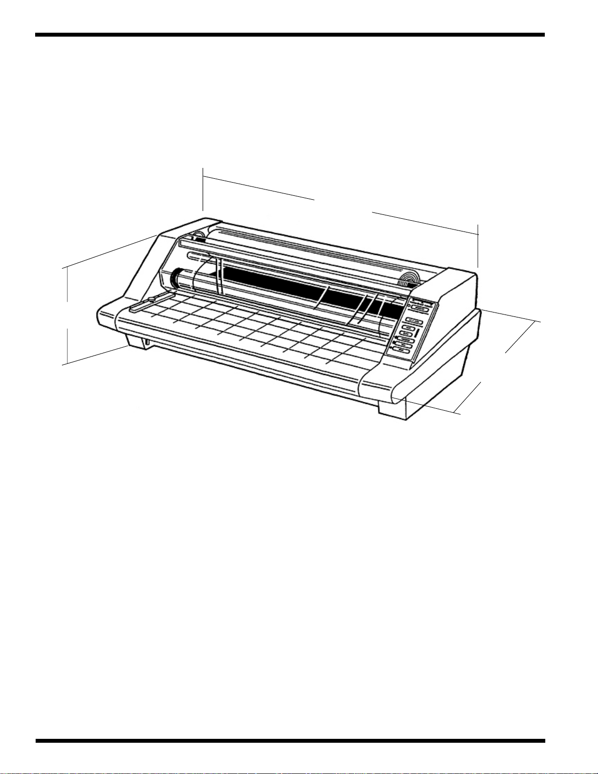
3.5 Dimensions (L x W x H)
Refer to Figure 3.5.1 Patriot 25E for an illustration.
21 x 32.5 x 12 inches
(53 x 83 x 31 cm)
3.3 Weight
Unpacked- 85 pounds (39 kg)
packed- 90 pounds (41 kg)
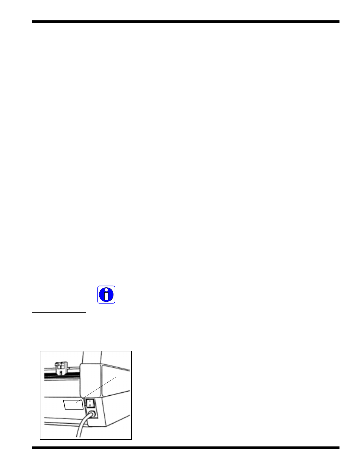
3.4 Electrical requirements
INFORMATION: Refer to the serial plate located
on the rear of the laminator for specific electrical
ratings applicable to the unit.
Serial
plate
© 2002 IBICO Page 3-1
Page 12
Patriot 25E
Figure 3.5.1 Patriot 25E
Operations Manual
32.5 in.
(83 cm)
12 in.
(31 cm)
21 in.
(53 cm)
© 2002 IBICOPage 3-2
Page 13

Operations Manual Patriot 25E
4.0 Installation
This section will guide you through the installation process
of the laminator.
INFORMATION: Shipping damage should be
brought to the immediate attention of the delivering
carrier.
4.1 Setting up the laminator
1.
Place the Patriot 25E on a stable flat surface capable
of supporting at least 95 lbs. (45kgs).
The surface should be at least 30 inches high to assure
comfortable positioning during operation.
2. The laminator should be positioned to allow exiting
film to drop freely to the floor.
CAUTION: Accumulation of laminate immediately
behind the laminator as it exits the equipment may
cause the film to wrap around the pull rollers,
resulting in a “jammed” condition.
3. Avoid locating the laminator near sources of heat or
cold. Avoid positioning the laminator in the direct path of
forced heated or cooling air.
INFORMATION: This effects the performance of
the heating system and could result in poor output
quality.
4. Connect the attachment plug provided with the
laminator to a suitably grounded outlet only.
CAUTION: Too high or too low of an operating
position can lead to serious bodily injury.
All four rubber support feet should be positioned
completely on the supporting surface.
CAUTION: The laminator is a heavy piece of
equipment and may cause injury if it falls and/ or
require extensive repair work.
The supporting surface may also be large enough to hold
the material being laminating.
Refer to Section 3.4 Electrical requirements
CAUTION: A void connecting other equipment to the
same branch circuit to which the laminator is
connected. This may result in sporadic tripping of
circuit breaker or blowing fuses.
© 2002 IBICO Page 4-1
Page 14
Patriot 25E
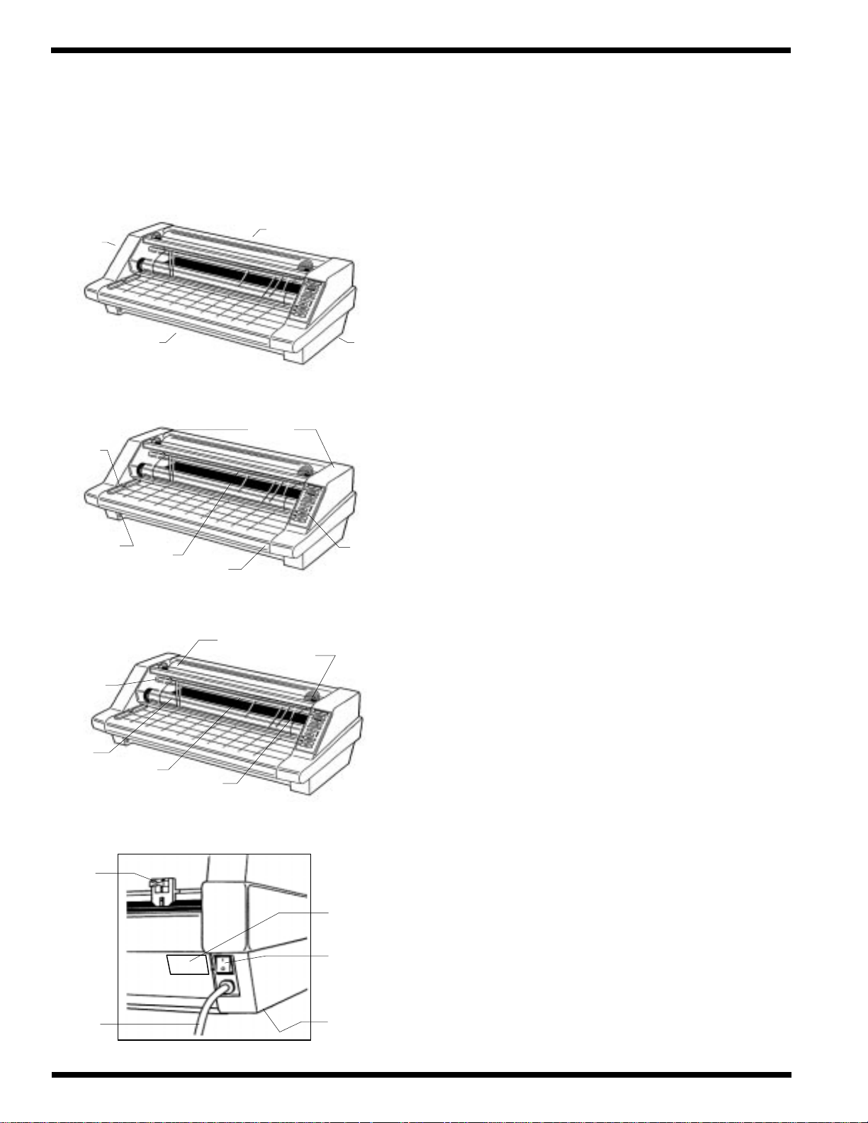
4.2 Know your laminator
This section will assist you in understanding what and
where items are when referred to in this manual.
Operations Manual
Drive
side
Feed
guide
Table
interlock
latch
Idler
Front
Safety
shield
Feed
table
Film
supply
Rear
Cabinets
Core
grips
Control
side
Control
panel
Heat
rollers
Rear
slitter
Power
cord
Pull
rollers
Film
web
Serial
plate
On/ Off
switch
Circuit
breaker
(under)
© 2002 IBICOPage 4-2
Page 15
Operations Manual Patriot 25E
5.0 Operation
This section covers the components of the
laminator, the control panel, the feed table, supply shaft,
film alignment, film loading and threading, film tension,
starting an application, speed guide, helpful hints and
important points to remember.
5.1 Components on the laminator
Refer to Section 4.2 Know your laminator
(1) POWER ON/ OFF: Located at the back of the left
side cabinet. When set to the “I” position, applies power
to the laminator. When set to the “O” position, removes
power to the laminator.
(5) FEED GUIDE: The feed guide permits alignment of
the item(s) to be laminated and is used to keep longer
items straight.
The feed guide may also be used to feed smaller items
side by side by positioning the guide towards the center
of the feed table and placing the smaller items against each
side of the feed guide as they are being introduced to the
nip point of the heat rollers.
To position the adjustable guide, loosen the knob on the
top of the guide, slide it to the desired position and tighten
the knob to secure in place.
(6) HEAT ROLLERS: Silicone rubber coated steel
tubes. Used to heat the laminating film and compress the
film to the items being laminated. Heat is provided by an
internal infrared element. The heat rollers are motor driven
for ease of loading new film.
(2) SAFETY SHIELD: Prevents entanglement,
entrapment and inadvertent contact with the heat rollers.
INFORMATION: The laminator will operate only
when the safety shield is located in the fully down
position. Power to the motor is removed when the
safety shield is in the raised position.
(3) FEED T ABLE: The feed table is used to position
items for lamination.
INFORMATION: The laminator will operate only
when the feed table is installed and the table
interlock latch is properly engaged.
WARNING: Avoid contact with the heat rollers.
Direct contact with the heat rollers can burn you.
(7) IDLER BAR: The idler bars, located near each
supply roll, are used to direct the film to the heat rollers.
The bottom idler is movable to ease film loading.
(4) T ABLE INTERLOCK LA TCH: Used to lock the
feed table into position and activate an interlock switch.
This interlock latch is located on the underside of the feed
table on the drive side from the front operating position.
The table can not be removed without retracting the latch
© 2002 IBICO Page 5-1
Page 16

Patriot 25 E Operations Manual
(8) PULL ROLLERS: The pull rollers, located at the
back of the laminator, are motor driven. They
simultaneously pull the film and improve the quality of the
laminated item.
(9) REAR SLITTER: Used to cut the film web where it
exits the rear of the laminator. To make a cut, press and
hold down the blade lever and slide across the rear of the
laminator.
(1 1) CORE ADAPTERS: The film shaft holds the supply
roll while the core adapters hold the rolls of film on the
shaft.
Thumb screws
Core adapters
(12) FILM WEB: Laminating film loaded into the machine
Film web
WARNING: Never reach over the laminator to
operate the film cutter . Reaching over can make you
unstable and may cause serious bodily injury.
CAUTION: Exercise extreme caution when working
around or replacing the film cutter blade. This blade
is sharp and can cut you.
(10) CIRCUIT BREAKER: Electrical safety device,
located under the drive side cabinet cover, can be reset
by the operator if tripped.
(13) NIP POINT : The point at which the top and bottom
rollers come into contact. The nip point of the heat rollers
is the place at which the items for lamination are introduced
into the laminator.
CAUTION: Only feed acceptable materials through
the nip of the rollers. Unacceptable materials may
cause damage to the rollers.
Nip point
CAUTION: If the circuit breaker trips a second time
after being reset, contact your service representative
for assistance.
© 2002 IBICOPage 5-2
Page 17

Operations Manual Patriot 25E
5.2 Control panel
Refer to Figure 5.2.1
(1) POWER: This light illuminates when power to the
laminator is “ON”. If this lamp is not lit, no power to the
laminator is being supplied.
(2) HEA T : Illuminates when the laminator is first turned
on and when the laminator calls for more heat.
(3) READY : Indicates when the laminator has sufficient
heat for the selected film gauge.
(4) ST ANDBY : Illuminates indicating the laminator is in
“STANDBY” mode. In standby mode, the temperature
is reduced. Press this button to revert to operating mode.
The temperature will restore itself to the predetermined
film gauge setting.
Figure 5.2.1 Control panel
(2)
(1)
(4)
(5)
(6)
(7)
POWER HEAT READY
STAND BY
FILM GUAGE
1.5 & 3 MIL
FAST
SLOW
REVERSE
RUN
(3)
(8)
(9)
(5) 1.5 & 3 MIL: This button must be pressed to set
temperature and speed settings required to for these
thicker gauge films.
(6) FAST: When pressed, increases the speed of the
laminator by overriding the preset condition.
(7) SLOW : When pressed, decreases the speed of the
laminator by overriding the preset condition.
(8) REVERSE: When pressed, reverses the roller
direction. Use this button to clear film jams and wrapups.
(9) RUN: When pressed, activates rollers for normal
operation.
STOP
IBICO
(10)
(10) STOP: When pressed, stops the movement of the
rollers.
© 2002 IBICO Page 5-3
Page 18

Patriot 25 E Operations Manual
y
5.3 Feed table
To remove
1.
Lift the safety shield to its full upright position.
2. Slide the feed table interlock latch to the right.
3. Lift the rear of the table (the rounded side) upwards
and then away from the laminator.
Raise safet
shield
5.4 Supply shaft
To remove
1.
Slide the upper shaft to the right from the front operating
position.
2. While pushing in on the supply shaft to the right, remove
the left side of the shaft from the brake assembly.
3. Raise the safety shield and remove the table and repeat
the steps above for the lower supply shaft.
To replace
Align the rounded end of the supply shaft into the supply
1.
shaft hole located on the right side of the laminator from
the front operating position.
Lift up the table and out
To replace
1.
Set the front of the feed table (the side that is not
rounded) into the table brackets first.
2. Lower the rear of the feed table onto the table support
bar.
3. Slide the table interlock latch to the left.
2. Push the supply shaft in while aligning the hex end of
the supply shaft with the brake assembly.
5.5 Film alignment
The film supply shafts come with pre alignment holes on
the right side for 9 in. (21 cm), 12 in. (31 cm), 18 in. (46
cm) , 25 in. (64 cm) and 27 in. (69 cm) film widths. Loosen
the locking screw on the right side core adapter and move
the to the corresponding hole to match the width of your
roll of film. Tighten the locking screw in the pre drilled
hole.
Thumb screws
4. Lower the safety shield to its fully closed position.
Core adapters
© 2002 IBICOPage 5-4
Page 19

Operations Manual Patriot 25E
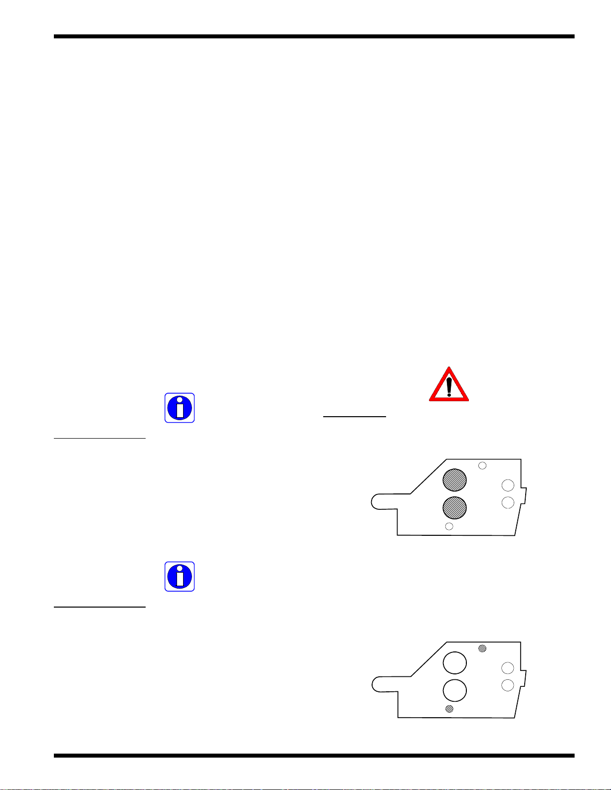
5.6 Adjusting film tension
Proper film tension, known as brake tension, is the
minimum amount of tension required to eliminate wrinkles
in the finished item.
The film tension is set at the factory. Periodic adjustments
should not be necessary unless other than 1.0, 1.5 or 3
mil film is being used or the lamination is curling up or
down.
The film should be taut. A properly adjusted roll of film
should not require excessive force to turn by hand. Film
tension should be enough to introduce a minor amount of
drag as the film unrolls.
Insufficient tension causes wrinkles while too much tension
between the top and bottom rolls creates curl. Too much
upper tension causes upward curl while too much bottom
tension causes a downward curl.
2. Rotate the roll of film until the lever engages the internal
mechanism.
3. Rotate the roll of film clockwise to increase tension
and counter clockwise to decrease tension.
Increase
Decrease
4. Release the brake lever and check the tension by
rotating the roll of film. Resistance should be slight, not
forced.
Follow the procedure described below to adjust film
tension.
1. To adjust the bottom brake, push and hold the brake
lever located on the left side frame by the roll of film.
Brake lever
5. Repeat steps above to adjust the top brake.
6. Run some test samples to verify proper brake tension.
Adjust if necessary.
© 2002 IBICO Page 5-5
Page 20

Patriot 25 E Operations Manual
This page intentionally left blank.
© 2002 IBICOPage 5-6
Page 21

Operations Manual Patriot 25E
6.0 Applications
The Patriot 25E will accommodate rolls of film on a 1 in.
(2.54 cm) and 2-1/4 in (5.72 cm) cores. This section
covers how to load and thread film and start an application.
A speed guide, helpful hints and important points to
remember are provided.
6.1 Film loading and threading
CAUTION: The laminator should be cool to the touch
before proceeding performing this procedure.
4. Slide the rolls of laminating film onto the unwind shafts
so the adhesive is facing away from the heat rollers when
replaced into the laminator.
CAUTION: The dull side of the film contains the
adhesive. Use extreme caution when loading
delustered (matte) film as both sides appear dull.
Adhesive side
Polyester side
CAUTION: The top and bottom rolls of film must
be of the same width and be present simultaneously .
Do not allow one roll of film to run out before the
opposite roll of laminating film.
1. Remove the feed table.
2. Remove the unwind shafts from the laminator. Remove
the core adapters from the unwind shafts.
3. Move the lower idler out of the locked position.
5. Align the film and secure the rolls of laminating film in
place by tightening the thumb screws located on the core
adapters.
INFORMA TION: If using standard rolls of film, use
the pre-aligned holes on the supply shaft.
6. Pull the lower roll of laminating film around the lower
idler and back towards the front of the laminator. Pull
enough film to allow it to drape over the roll.
© 2002 IBICO Page 6-1
Page 22

Patriot 25E
Operations Manual
7. Move the lower idler into the locked position.
8. Pull the upper laminating film down over the upper
idler and drape over the heat rollers.
10. Slide the threading card ( a piece of heavy stock
paper, card board or similar product) between the feed
table and the film resting on the feed table. Push the
threading card into the nip of the heat rollers.
11. Tun power to ON and press RUN.
9. Slide the feed table under the draped film from the
lower supply roll and replace the feed table ensuring the
film stays on top of the feed table. Lower the safety shield
into the fully closed position.
12. Once the threading card has completely exited the
rear of the laminator, press STOP.
13. Trim the threading card off using the rear slitter.
© 2002 IBICOPage 6-2
Page 23

Operations Manual Patriot 25E
6.2 Starting an application
CAUTION: Ensure the safety shield is in the fully
closed position and the feed table is properly installed
with the table interlock latch in position.
1. Turn the laminator on by pushing ON/OFF to the “I”
position.
2. The laminator will automatically default to the 1.5 & 3
MIL setting.
3. The laminator will set the speed and temperature for
the respective film and 20 lb. bond paper (copier paper).
5. Position the item(s) on the feed table to be laminated.
6. Ensure the rear slitter is completely to one side on the
laminator.
CAUTION: Anything obstructing the path of the film
exiting the rear of the laminator may cause a film
jam (wrap-up).
7. Press RUN. The rollers will begin to turn.
8. Wait for the heat line (dwell line) to disappear, then
push the items into the nip point of the heat rollers.
Additional items can be laminated without stopping and
starting the laminator.
INFORMATION: Decrease speed by pressing
SLOW if laminating heavier stock. Increase speed
by pressing F AST if you are laminating lighter stock.
Refer to Section 4.6 Speed guide and helpful hints
INFORMATION: HEAT may illuminate if
increasing speed to high. If the adhesive is not
activating (becomes tacky), slow the speed down to
achieve quality lamination.
9. Once the last item laminated has completely exited the
rear of the laminator, press the STOP.
10. Use the rear slitter to trim the laminated items from
the web.
WARNING: Never reach over the laminator to
operate the film cutter . Reaching over can make you
unstable and may cause serious bodily injury .
11. Turn the laminator off by pushing the On/Off switch
to the “O” position.
4. Adjust the feed guide while you wait for READY to
illuminate. Do not run any material through the laminator
until READY has illuminated.
INFORMATION: You do not need to un-web the
laminator after turning power off except to clean the
rollers. Refer to Section 7.2 Clean the rollers.
© 2002 IBICO Page 6-3
Page 24

Patriot 25E
6.3 Speed guide
The following chart provides general guidelines for proper
speed settings to use on certain materials and laminating
film combinations.
INFORMATION: Different settings may become
necessary as the warm up time, lamination time and
materials change.
Figure 6.3.1 Speed guide
Operations Manual
Material
Newspaper
20 lb. copier paper
Magazine stock
Tissue stock
Construction paper
Posters
Index cards
File folders
Poster boards
1.5 mil
(0.0015")
5
4
3
Film thickness
3.0 mil
(0.0030")
3
2
1
© 2002 IBICOPage 6-4
Page 25

Operations Manual Patriot 25E
6.4 Helpful hints
Good consistent lamination is a result of combining proper
heat, speed, tension and dwell time. Dwell time is the
amount of time the material to be laminated is compressed
between the heat rollers and is controlled by the speed of
the laminator.
As a general rule, thicker items and films as well as items
with dark or full ink coverage, need to run at a slower
speeds because they extract more heat from the rollers at
a quicker rate.
Thinner items, such as standard copier paper (20lb.bond)
and tissue stock, extract less heat from the rollers and can
be run at faster speeds.
Operation of the laminator for more than thirty minutes at
a time may necessitate a lower speed setting. It is
recommended that during periods of long runs the items
being laminated are alternated between thick and thin.
6.5 Important points to remember
WARNING: Do not press RUN until READY has
illuminated.
WARNING: To cut film or web, only use the rear
slitter or an enclosed blade around the laminator .
WARNING: Do not force items into the laminator .
An item that is not easily drawn into the laminator is
probably to thick to laminate.
If you are ever unsure that your laminator is set at proper
speed, run a test piece (scrap) of the same or similar
material through the laminator. Rotating the heat rollers
prior to laminating distributes the heat evenly throughout
the heat rollers.
Always change the top and bottom supply rolls at the
same time. This will prevent adhesive from getting on the
rollers. Adhesive will deposit on the rollers if:
– Only one roll of film is used.
– Different widths of rolls are loaded together.
– Either roll is loaded adhesive side against a heat
roller.
– One or both rolls of film are allowed to run
completely off the cores.
Always use the minimum brake tension necessary to
achieve the desired results. Using the maximum amount
will yield unwanted results after close inspection. You may
see stretching, waves in the laminate, distortion of the image
and/ or curling.
WARNING: Do not attempt to laminate abrasive
or metal objects such as staples, paper clips and
glitter as they may damage the heat rollers.
WARNING: Do not attempt to laminate adhesives
marked “FLAMMABLE”.
CAUTION: A void direct contact with the heat rollers
when changing the supply rolls after the laminator
has been running.
© 2002 IBICO Page 6-5
Page 26

Patriot 25E
CAUTION: Do not stop the laminator before an item
has completely exited the pull rollers. Even a
momentary stop will cause a dwell line (heat line) on
the laminated item.
INFORMA TION: W rinkles may result if an attempt
is made to reposition an item once it has entered
the nip of the heat rollers.
Operations Manual
INFORMATION: When feeding long items,
skewing may occur if the item is not fed into the
laminator straight. Use the feed guide to help prevent
this from happening.
INFORMATION: When feeding two items into the
laminator , do not mix thin and thick items together
as this will create a poor edge seal.
INFORMATION: If the machine is not working,
always check that the safety shield is properly
closed, the feed table is properly installed and the
circuit breaker has not tripped before placing a
service call.
© 2002 IBICOPage 6-6
Page 27

Operations Manual Patriot 25E
7.0 Maintenance &
Troubleshooting
IBICO laminators require minimal maintenance. However,
regular maintenance is essential to keep any piece of
precision machinery at peak performance. A maintenance
schedule and a section of procedures are included in this
section.
WARNING: Do not wear ties, loose fitting clothes
or dangling jewelry while operating or servicing the
laminator . These items can get caught in the nip and
choke you or you can be crushed or burned.
7.1 Cabinets, cover and stand
ELECTRICAL HAZARD: Remove power from the
laminator before cleaning. You can be severely
shocked, killed or cause a fire.
1. Use a damp ( use water only to dampen the cloth )
white terry cloth towel to wipe dust from the cabinets,
cover and stand.
7.2 Clean the rollers
INFORMA TION: Impr oper maintenance can result
in poor output quality.
IBICO offers Cleaning kits ( P/N 1711515 ) as well as
Extended Maintenance Agreements.
The only maintenance required by the operator is to
maintain clean and adhesive free nip rollers and overall
cleanliness of the laminator itself.
ELECTRICAL HAZARD: Do not use liquid or
aerosol cleaners on the laminator . Do not spill liquid
of any kind on the laminator. You can be severely
shocked, killed or cause a fire. Use only a damp cloth
for cleaning unless other wise specified.
CAUTION: This procedure is performed while the
laminator is HOT! Use extreme caution. Direct
contact with the rollers can burn you!
CAUTION: Hardened adhesive deposits on the
rollers can cause damage to the rollers. Rotate the
rollers at the lowest speed setting on the control
panel.
WARNING: Do not apply cleaning fluids or solvents
to the rollers! Fluids and solvents will have a direct
effect on the rubber coated rollers and will require
replacement.
WARNING: Do not use metal scouring pads to clean
the rollers! Scouring pads will damage the rollers
and require replacement.
© 2002 IBICO
Page 7-1
Page 28

Patriot 25E
Operations Manual
7.3 Troubleshooting
WARNING: Never clean the rollers with sharp or
pointed objects.
1. Remove the film from the laminator.
2. Preheat the laminator until the READY indicator
illuminates.
3. Rub the top and bottom heat rollers with a 3M
TM
Brite
pad.
TM
Scotch-
4. Install the feed table and lower the safety shield.
5. Press RUN to rotate the heat rollers to a new area for
cleaning. Press STOP. Continue this process until the
complete surface of both rollers are clean.
As an operator, you can perform some basic
troubleshooting before contacting your local service
representative.
WARNING: Never remove the cabinets in attempt
to troubleshoot the laminator . Y ou may cause damge
to other components or injury to yourself.
ELECTRICAL HAZARD: Do not remove the
cabinets. Y ou will be exposed to danger ous voltage
which can shock or paralyze you.
6. Follow the procedure in Section 4.6 Film loading and
threading to reload the laminator.
CAUTION: Only trained technicians should perform
service related work on the laminator .
Refer to Figure 7.3.1 T roubleshooting Guide on page
7-3.
Page 7-2
© 2002 IBICO
Page 29

Operations Manual Patriot 25E
Figure 7.3.1 Troubleshooting guide
Symptom
POWER lamp does
•
not illuminate when ON/ OFF
isin the ON position.
• Heat rollers do not turn.
• Laminated items exhibit
wrinkles.
• Adhesive deposited on the
heat rollers.
Possible cause
Laminator not connected to the
electrical supply.
Circuit breaker open.
Safety shield in upright position.
Feed tray interlock pin not in place.
Tension on top or bottom roll of
film is too loose.
Bottom film roll may be improperly
loaded.
Top and bottom film webs not
aligned.
Corrective action
Insert attachment plug into receptacle.
Reset circuit breaker.
Lower safety shield.
Slide interlock lever all the way into the left side
frame.
Adjust tension per section Film Tension
Adjustment.
Makesure the bottom roll of film is around the
idler bar.
Align film webs per section Film Alignment.
• Unsatisfactory adhesion of
laminate.
Laminate improperly loaded.
Speed setting too fast for type of
material being laminated.
Insufficient heat.
Laminate improperly loaded.
Heat rollers require cleaning.
Laminated item unsuitable for
adhesion.
Adhesive (matte) side of laminate film may be
against the heat rollers. Load film per procedure
outlined in section Film Loading and
Threading.
Lower speed setting by pressing SLOW.
READY must be illuminated.
Adhesive side of film must be facing away from
the heat rollers. Bottom roll of film not threaded
behind the idler bar.
Clean heat rollers per section T o Clean The
Rollers.
Item may be dirty or may have non-porous
surface that is extremely difficult to laminate.
© 2002 IBICO
Page 7-3
Page 30

Patriot 25E
This page intentionally left blank.
Operations Manual
Page 7-4
© 2002 IBICO
Page 31

Operations Manual Patriot 25E
8.0 Recommended spares
8.1 Spare parts list
Part # Item Description Quantity Drawing ref.
613050221 Rear slitter blade 1 P25E-001
604022032 T able guide knob 2 P25E-002
706011113 Control panel board 1 P25E-003
705200201 Infrared sensor 1 P25E-005
610010211 120V T ransformer 1 P25E-005
70601 11 14 Main PCB 1 P25E-006
704090102 Power ON/ OFF switch 1 P25E-006
704091045 Circuit breaker 1 P25E-006
704090415 Table micro-switch 1 P25E-006
704090414 Safety micro-switch 2 P25E-006
607040561 Pul l roller 2 P25E-007
706025028 Heater 2 P25E-007
704150107 Thermostat 1 P25E-007
607040556 Main roller 2 P25E-007
701080233 1/4 in. chain gear 1 P25E-007
6090202 DC motor 1 P25E-008
701070150 Roller chain 1 P25E-008
© 2002 IBICO
Page 8-1
Page 32

Patriot 25E
This page intentionally left blank.
Operations Manual
Page 8-2
© 2002 IBICO
Page 33

Operations Manual Patriot 25E
9.0 Illustrated Parts
WARNING: Illustrated parts drawings are to be
used only for ordering parts. They should not be used
to perform repair work yourself. Contact your local
service representative for service.
The parts list is in muneric order. The parts illustration are
in assembly order. If a part you rquire does not exist in
the parts list or in the parts illustration section, contact
you local service representative for assistance.
INFORMATION: The numeric value in the ( ),
represent quanity per machine, not per assembly .
9.1 Parts list
Part # Item Description QTY Unit
601230453 Roller cover 1 EA
601230521 Infrared heater support 2 EA
601230702 Inner tension panel 2 EA
601230802 Film shaft support panel 2 EA
601230804 Idler housing 1 EA
601250121 Side plate (L) 1 EA
601250122 Side plate (R) 1 EA
601250123 Film tension lever 2 EA
601250124 Power panel 1 EA
601250125 Circuit breaker support 1 EA
601250126 Sensor bracket 1 EA
601310501 Infrared heater inner support (N) 2 EA
601310504 Idler gear support 1 EA
601310508 Micro-switch support bracket 1 EA
601310509 P/R tension lever (L) 1 EA
601310510 P/R tension lever (R) 1 EA
601310511 Front lever fixing panel 1 EA
601310512 Tension adjustment panel 2 EA
601310521 Infrared heater outer support (N) 2 EA
604022032 Paper guide knob 2 EA
604022106 Paper guide 1 EA
604022111 Side cover (L) 1 EA
604022112 Side cover (R) 1 EA
604036131 Film guide screen (UP) 1 EA
604036133 Front base plate 1 EA
© 2002 IBICO
Page 9-1
Page 34

Patriot 25E
Operations Manual
Part # Item Description QTY Unit
604036135 Rear cover (UP) 1 EA
604036136 Rear cover (LOW) 1 EA
604036137 Roller cover cap 1 EA
604036138 Front table 1 EA
604037011 H/R roller hook 2 EA
604037021 1 in. core grippers 4 EA
607040556 H/ roller 2 EA
607040561 P/ roller 2 EA
6090202 DC geared motor (DM010) 1 EA
610010211 Transformer GM6635A-12 1 EA
613030151 Tie bar (PL) 1 EA
613030161 Upper idler roller (PL) 1 EA
613030162 Lower idler roller (PL) 1 EA
613030211 Hex film shaft (PL) 2 EA
613030301 Film Shaft Bushing (PL) 2 EA
613030527 Core bushing bolt (PL) 4 EA
613030537 Film tension bolt (PL) 2 EA
613030538 P/R tension bolt (PL) 2 EA
613030539 P/R support pin (PL) 2 EA
613030540 Auxiliary gear support pin (PL) 3 EA
613030541 Feed table hook support pin (PL) 2 EA
613030612 Roller cover support pin (PL) 1 EA
613030613 Feed table safety lever (PL) 1 EA
613040131 Column bushing (PL) 4 EA
701020209 Drawn needle bearing 4 EA
701050234 Flange bushing 6 EA
701050240 Flange bushing 4 EA
701070150 Roller chain 1 EA
701080233 Steel 1/4 chain gear 1 EA
701080265 Steel 1/4 chain gear 1 EA
701080271 Steel 1/4 chain gear 1 EA
701090115 Roller spring 2 EA
701090142 Film pipe spring 2 EA
701090157 Pull spring 2 EA
701090158 Compressed coil spring 2 EA
701090160 Feed table coil spring 1 EA
701090606 Spring ring 2 EA
701090832 Spring ring 2 EA
701090844 Spring ring 1 EA
701091201 R pin 2 EA
Page 9-2
© 2002 IBICO
Page 35

Operations Manual Patriot 25E
Part # Item Description QTY Unit
701104803 T/S truss head 2 class T3.0 TH 6 EA
701106603 Set screw hexagon socket 2 EA
701110101 Nut 2 EA
701110104 Nut 2 EA
703010111 Rubber foot 4 EA
703010211 Wire protection ring 2 EA
703010332 Holder 4 EA
703020243 Control panel 1 EA
703020581 PC control key 1 EA
703020582 PC control key 1 EA
703020583 PC control key 1 EA
703020584 PC control key 1 EA
703020585 PC control key 1 EA
703020586 PC control key 1 EA
703020587 PC control key 1 EA
703070101 Friction panel (Leather) 4 EA
704030316 Cord plug 125 V UL 1 EA
704090102 Power S/W rocker 1 EA
704090313 Rubber key S/W 1 EA
704090414 Table micro-switch 3 EA
704090415 Safety micro-switch 1 EA
704091045 Circuit breaker 1 EA
704140403 Cord stopper 1 EA
704150107 Bi-metal thermostat 1 EA
705200201 Infrared sensor 1 EA
706011113 PCB display 1 EA
706011114 PCB main 1 EA
706025028 Infrared heater 2 EA
706111121 Back trimmer assembly 1 EA
802034301 PATRIOT decal (FRONT) 1 EA
802105042 Control panel decal 1 EA
803040379 Speed guide line decal 1 EA
© 2002 IBICO
Page 9-3
Page 36

Page 9-4
MATERIAL DISCLOSED ON THIS DR AWING. IT IS ISSUED IN CONFIDENCE
FOR ENGINEERING INFORMAT ION ONLY AND SHALL NOT BE REPROD UCED,
MANUFACTURE OR FOR ANY OTHER PURPOSE WITHOUT WRITTEN
PROPRIETARY
GBC PRO-TECH CLAIMS PROPRIETARY RIGHTS TO THE
COPIED OR DISCLOSED IN WHOL E OR IN PART, OR USED FOR
PERMISSION FROM GBC PRO-TECH
(2) 701110101
Patriot 25E
C
(1) 604022108
Knife Lever
Nut M3
(1) 613050221
Knife Blade
© 2002 IBICO
(1) 604022107
Knife Block
(1) 701090159
Spring
(2) 701104803
Truss Head Screw
UNLESS OTHERW I SE SPECIFIED
DIM. AS
SHOWN
X/X
X
REVISION
XX
XXX
XXXX
CHECKED BY : GBC FILMS G ROUP
This print is the property of GBC Films Group. The information thereon is remitted in confidence.
TOLERANCE
TOL.
+ 1/64
+ .050
+ .010
+ .020
+ .005
FINISH
TO BE
125
ANGLES
+ 1D
GBC Films Group
4151 Anderson Road, DeForest, WI 53532
TITLE :
Assembly, Slitter
Patriot 25E
DRAWN BY :
DATE :
DWG SCALE :
Operations Manual
DWG :
P25E-001N/ANSG07/01/02
Page 37

© 2002 IBICO
PROPRIETARY
GBC PRO-TECH CLAIMS PROPRIETARY RIGHTS TO THE
MATERIAL DISCLOSED ON THIS DRA WING. IT IS ISSUED IN CONFIDENCE
FOR ENGINEERING INFORMATION ONLY AND SHALL NOT BE REPRODUCED,
COPIED OR DISCLOSED IN WHOLE OR IN PART, OR USED FOR
MANUFACTURE OR FOR ANY OTHER PURPOSE WITHOUT WRITTEN
PERMISSION FROM GBC PRO-TECH
Operations Manual Patriot 25E
C
(1) 802034301
Patriot Nme Sticker
(1) 803040379
S
T
IN
O
P
SPEED
3 MIL
G
IN
T
1
R
FILM THICKNESS
TA
S
GUIDELINES
D
TE
S
E
G
R
G
E
U
T
S
A
M
osters
P
onstru
C
2
1.5 MIL
L
3
IA
ctio
aper
P
20# B
C
3
4
n
5
nod
per
a
er
aper
opler P
ap
sp
e P
ew
N
issu
T
(1) 604022112
Side Cover
Serial Tag
Page 9-5
(1) 604022111
Side Cover (L)
(2) 604022032
Guide Knob
(1) 604022106
Paper Guide
(1) 604036138
Front Table
UNLESS OTHERWI SE SPECIFIED
DIM. AS
SHOWN
X/X
REVISION
XX
XXX
XXXX
CHECKED BY : GBC FILMS GRO UP
This print is the property of GBC Films Group. The information thereon is remitted in confidence.
TOLERANCE
FINISH
TOL.
TO BE
+ 1/64
125
+ .050
X
+ .010
+ .020
ANGLES
+ 1D
+ .005
GBC Films Group
4151 Anderson Road, DeForest, WI 53532
TITLE :
Assembly, Covers and Table
Patriot 25E
DRAWN BY :
DATE :
DWG SCALE :
DWG :
P25E-002N/ANSG07/01/02
Page 38

Page 9-6
MATERIAL DISCLOSED ON THIS DRA WING. IT IS ISSUED IN CONFIDENCE
FOR ENGINEERING INFORMATION ONLY AND SHALL NOT BE REPRODUCED,
PROPRIETARY
GBC PRO-TECH CLAIMS PROPRIETARY RIGHTS TO THE
COPIED OR DISCLOSED IN WHOLE OR IN PART, OR USED FOR
MANUFACTURE OR FOR ANY OTHER PURPOSE WITHOUT WRITTEN
PERMISSION FROM GBC PRO-TECH
Patriot 25E
C
(1) 802105042
Decal Overlay
(1) 703020243
Pat25E Control Panel
(1) 703020581
Stand by
(1) 703020582
1.5 & 3 Mil.
(1) 703020583
Fast
(1) 703020584
Slow
(1) 703020585
Reverse
© 2002 IBICO
(1) 703020586
Run
(1) 703020587
Stop
(1) 704090313
Touch Pad Control
(1) 706011113
Control Board
(5) 701104803
Fasteners
DIM. AS
SHOWN
REVISION
XXXX
CHECKED BY : GBC FILMS GRO UP
This print is the property of GBC Films Group. The information thereon is remitted in confidence.
UNLESS OTHERWI SE SPECIFIED
TOLERANCE
FINISH
TOL.
X/X
XX
XXX
TO BE
+ 1/64
125
+ .050
X
+ .010
+ .020
ANGLES
+ 1D
+ .005
GBC Films Group
4151 Anderson Road, DeForest, WI 53532
TITLE :
Assembly, Control Panel
Patriot 25E
DRAWN BY :
DATE :
Operations Manual
DWG SCALE : DWG :
P25E-003N/ANSG07/01/02
Page 39

© 2002 IBICO
PROPRIETARY
GBC PRO-TECH CLAIMS PROPRIETARY RIGHTS TO THE
MATERIAL DISCLOSED ON THIS DRA WING. IT IS ISSUED IN CONFIDENCE
FOR ENGINEERING INFORMATION ONLY AND SHALL NOT BE REPRODUCED,
COPIED OR DISCLOSED IN WHOLE OR IN PART, OR USED FOR
MANUFACTURE OR FOR ANY OTHER PURPOSE WITHOUT WRITTEN
PERMISSION FROM GBC PRO-TECH
C
(1) 604036131
Film Guide Screen
Operations Manual Patriot 25E
(1) 604036137
Roll Cover Cap
(1) 601230453
Roller Cover
(2) 613030301
Film Shaft Bushing
(4) 613030527
Core Bush Bolt
(2) 613030211
Film Shaft
Page 9-7
(1) 613030612
Cover Support Pin
(1) 701090844
Spring Pin
(4) 604037021
1in. Core
UNLESS OTHERWI SE SPECIFIED
DIM. AS
SHOWN
X/X
X
REVISION
XX
XXX
XXXX
CHECKED BY : GBC FILMS GRO UP
This print is the property of GBC Films Group. The information thereon is remitted in confidence.
TOLERANCE
TOL.
+ 1/64
+ .050
+ .010
+ .020
+ .005
FINISH
TO BE
125
ANGLES
+ 1D
GBC Films Group
4151 Anderson Road, DeForest, WI 53532
TITLE :
Assembly, Cover And Film Shaft
Patriot 25E
DRAWN BY :
DATE :
DWG SCALE :
DWG :
P25E-004N/ANSG07/01/02
Page 40

Page 9-8
MATERIAL DISCLOSED ON THIS D RAWING. IT IS ISSUED IN CONFIDENCE
FOR ENGINEERING INFORMATION ONLY AND SHALL NOT BE REPRODUCED,
PROPRIETARY
GBC PRO-TECH CLAIMS PROPRIETARY RIGHTS TO THE
COPIED OR DISCLOSED IN WHOL E OR IN PART, OR USED FOR
MANUFACTURE OR FOR ANY OTHER PURPOSE WITHOUT WRITTEN
PERMISSION FROM GBC PRO-TECH
C
120V Transformer
Back Trimmer Assy.
(1)610010211
(1)604036135
(1)613030151
Tie Bar
Patriot 25E
(1)7050703
© 2002 IBICO
(1)604036136
Rear Cover, Lower
(1)706111121
Back Trimmer Assy.
(1)601230112
(1)705200201
Infrared Sensor
(1)601250126
Sensor Bracket
(1)601220132
Front Base Plate (Low)
(4)703010111
Rubber Foot
(1)601250122
Side Plate (R)
(1)604036133
Front Base Plate (up)
Operations Manual
(1)601250121
Side Plate (L)
DIM. AS
SHOWN
REVISION
XXXX
CHECKED BY : GBC FILMS GROUP
This print is the property of GBC Films Group. The information thereon is remitted in confidence.
UNLESS OTHERW ISE SPECIFIED
TOLERANCE
FINISH
TOL.
X/X
X
XX
XXX
TO BE
+ 1/64
125
+ .050
+ .010
+ .020
ANGLES
+ 1D
+ .005
GBC Films Group
4151 Anderson Road, DeForest, WI 53532
TITLE :
Assembly, frame
Patriot 25E
DRAWN BY :
DATE :
DWG SCALE :
DWG :
P25E-005N/ANSG07/01/02
Page 41

© 2002 IBICO
PROPRIETARY
GBC PRO-TECH CLAIMS PROPRIETARY RIGHTS TO THE
MA TER IAL DISC LOS ED O N T H IS D R AW ING . IT IS ISS UE D IN C O NFID EN C E
FOR ENGINEERING INFORMATION ONLY AND SHALL NOT BE REPRODUCED,
COPIED OR DISCLOSED IN WHOLE OR IN PART, OR USED FOR
MANUFACTURE OR FOR ANY OTHER PURPOSE WITHOUT WRITTEN
PERMISSION FRO M G B C PRO-TEC H
Operations Manual Patriot 25E
(2) 601250123
C
Film Tension Leve r
(3) 704090414
Micro Switch
Page 9-9
(1) 704030316
Cord Plug (120V)
(1) 704140403
Cord Stopper
(1) 706011114
A
Main PCB (120V)
(1) 704090102
Power Switch
(1) 601250124
Power Panel
(1) 704091045
Circuit Breaker
(2) 703010211
Wire Protect
(1) 601250125
Circuit Breaker Support
(2) 601310512
Tension Adj. Panel
(2) 701090606
Spring E Ring
(2) 701091201
Pin
Film Pipe Spring
(2) 701090142
(4) 703070101
Friction Panel
(2) 601230702
Inner Tension Panel
DCN # 03-0001
A
DIM. AS
SHOWN
REVISION
CHECKED BY : GBC FILMS GROUP
(2) 613030537
Film Tension Bolt
(1) 601310508
Micro Sw. Support
(1) 704090415
Micro Switch
This p rint is th e p roper ty o f G B C Film s G roup. T he info r m ation t h e reon is r e m itted in c onfide n ce.
UNLE S S OTHER WISE S P ECIFIE D
TOLERANCE
FINISH
TOL.
X/X
X
XX
XXX
XXXX
TO BE
+ 1/64
125
+ .050
+ .010
+ .020
ANGLES
+ 1D
+ .005
GBC Films Group
4151 Anderso n R o ad, DeF o rest, WI 53532
TITLE :
Assembly, Control side
Patrio t 2 5E
DRAWN BY :
DATE :
(2) 701090832
Spring Pin
601230713
DWG :
DWG SCALE :
P25E-001N/ANSG07/01/02
Page 42

Page 9-10
MATERIAL DISCLOSED ON THIS DRA WING. IT IS ISSUED IN CONFIDENCE
FOR ENGINEERING INFORMATION ONLY AND SHALL NOT BE REPRODUCED,
COPIED OR DISCLOSED IN WHOLE OR IN PART, OR USED FOR
MANUFACTURE OR FOR ANY OTHER PURPOSE WITHOUT WRITTEN
(4) 613040131
Column Bushing
PROPRIETARY
GBC PRO-TECH CLAIMS PROPRIETARY RIGHTS TO THE
PERMISSION FROM GBC PRO-TECH
(1) 601310509
Tension Lever (L)
(2) 701090157
Pull Spring
C
(4) 701050240
Bushing Frange
(2) 613030538
Tension Bolt
(2) 607040561
Pulll Roller
(1) 701080233
1/4 in. Chain Gear
(1) 601310510
P/R Tension Lever (R)
(2) 701110104
Nut
(2) 601230521
Heater Support
Patriot 25E
(1) 613030161
Up Idle Roller
(1) 601230804
Idler Housing
(4) 703010332
Holder
(2) 601310521
Outer Support
(2) 601310501
Inner Support
(2) 701080271
1/4 in. Chain Gear
(2) 613030541
Table Support Pin
(2) 613030539
P/R Support Pin
(2) 701106603
Set Screw
© 2002 IBICO
(2) 706025028
Heater
(2) 701090115
Roller Spring
(2) 701090718
S Ring
(1) 704150107
Thermostat
(2) 604037011
Roller Hook
(2) 607040556
(4) 701020209
Niddle Bearing
H/Roller
Gear Support Pin
(1) 701050234
Bushing Frange
(1) 613030162
Low Idle Roller
This print is the property of GBC Films Group. The information thereon is remitted in confidence.
UNLESS OTHERWI SE SPECIFIED
TOLERANCE
DIM. AS
TOL.
SHOWN
X/X
+ 1/64
+ .050
X
REVISION
XX
+ .010
+ .020
XXX
+ .005
XXXX
CHECKED BY : GBC FILMS GRO UP
ORIGINATOR : GMP
(3) 613030540
(1) 613030151
GBC Films Group
4151 Anderson Road, DeForest, WI 53532
FINISH
TO BE
TITLE :
125
Assembly, rollers and heaters
Patriot 25E
DATE :
ANGLES
+ 1D
Tie Bar
DRAWN BY :
DWG SCALE :
Operations Manual
DWG :
P25E-001N/ANSG07/01/02
Page 43

© 2002 IBICO
PROPRIETARY
GBC PRO-TECH CLAIMS PROPRIETARY RIGHTS TO THE
MATERIAL DISCLOSED ON THIS DRA WING. IT IS ISSUED IN CONFIDENCE
FOR ENGINEERING INFORMATION ONLY AND SHALL NOT BE REPRODUCED,
COPIED OR DISCLOSED IN WHOLE OR IN PART, OR USED FOR
MANUFACTURE OR FOR ANY OTHER PURPOSE WITHOUT WRITTEN
PERMISSION FROM GBC PRO-TECH
Operations Manual Patriot 25E
C
Page 9-11
(1) 6090202
DC Motor
(2) 613030541
Feed Table Hook Support
(2) 601230802
Film Shaft Support
(2) 703010211
Wire Protect Ring
(2) 701090158
Compressed Coil Spring
(1) 613030540
Gear Support Pin
(1) 701080266
Chain Gear
(1) 701080265
Chain Gear
This print is the property of GBC Films Group. The information thereon is remitted in confidence.
UNLESS OTHERWI SE SPECIFIED
TOLERANCE
DIM. AS
TOL.
SHOWN
X/X
+ 1/64
+ .050
X
REVISION
XX
+ .010
+ .020
XXX
+ .005
XXXX
CHECKED BY : GBC FILMS GRO UP
(1) 701070150
Roller Chain
Idle Gear Support
GBC Films Group
4151 Anderson Road, DeForest, WI 53532
FINISH
TO BE
TITLE :
125
Assembly, drive side
Patriot 25E
DATE :
ANGLES
+ 1D
(1) 601310504
DRAWN BY :
DWG SCALE :
DWG :
P25E-008N/ANSG07/01/02
Page 44

Page 9-12
MATERIAL DISCLOSED ON THIS DRA WING. IT IS ISSUED IN CONFIDENCE
FOR ENGINEERING INFORMATION ONLY AND SHALL NOT BE REPRODUCED,
COPIED OR DISCLOSED IN WHOLE OR IN PART, OR USED FOR
MANUFACTURE OR FOR ANY OTHER PURPOSE WITHOUT WRITTEN
PROPRIETARY
GBC PRO-TECH CLAIMS PROPRIETARY RIGHTS TO THE
PERMISSION FROM GBC PRO-TECH
Patriot 25E
C
(1) 613030613
Feed Table Safety Lever
(1) 601310511
Front Lever Fixing Panel
© 2002 IBICO
(1) 701090160
Feed Table Coil Spring
(1) 701090721
Snap Ring
DIM. AS
SHOWN
REVISION
XXXX
CHECKED BY : GBC FILMS GRO UP
This print is the property of GBC Films Group. The information thereon is remitted in confidence.
UNLESS OTHERWI SE SPECIFIED
TOLERANCE
FINISH
TOL.
X/X
X
XX
XXX
TO BE
+ 1/64
125
+ .050
+ .010
+ .020
ANGLES
+ 1D
+ .005
GBC Films Group
4151 Anderson Road, DeForest, WI 53532
TITLE :
Assembly, Latch
Patriot 25E
DRAWN BY :
DATE :
DWG SCALE :
Operations Manual
DWG :
P25E-009N/ANSG07/01/02
Page 45

© 2002 IBICO
PROPRIETARY
GBC PRO-TECH CLAIMS PROPRIETA RY RIGHTS TO THE
MATERIAL DISCLOSED ON THIS DRAW ING. IT IS ISSUED IN CONFIDENCE
FOR ENGINEERING INFORMATION ONLY AND SHALL NOT BE REPRODUCED,
COPIED OR DISCLOSED IN WHOLE OR IN PAR T, OR USED FOR
MANUFACTURE OR FOR ANY OTHER PURPOSE WITHOUT WRITTEN
PERMISSION FROM GBC PRO-TECH
1
STAND_BY
ECONOMY
STANDARD
FAST
SLOW
REVERSE
RUN
STOP
TYPE NO:4PK-G4265D
TYPE NO:4PK-G4265D
Operations Manual Patriot 25E
1
DISPALY PCB
2
C
PATRIOT 25E WIRE DIAGRAM(120/60)
14
R12
LD010
TOP IR SENSOR
TABLE MICRO SWITCH 1
3
TABLE MICRO SWITCH 2
4
I_LOCK MICRO SWITCH1
5
TRANS GM6635A-12
6
TOP HEATER
7
BOTTOM HEATER
8
TOP THERMOSTAT
9
BOTTOM THERMOSTAT
10
POWER CORD
11
POWER SWITCH 15A
12
13
CIRCUIT BREAKER
MAIN PCB DRIVE
14
15
MAIN MOTOR
I_LOCK MICRO SWITCH2
16
13
Page 9-13
9
7
15
6
2
16
3
4
5
10
8
DIM. AS
SHOWN
REVISION
XXXX
CHECKED BY : GBC FILMS GROUP
11
This print is the pr op erty of GBC Films Group. The i nf o rmation thereon is remitt ed in confidence.
UNLESS OTHERWISE SPECIFIED
TOLERANCE
FINISH
TOL.
X/X
XX
XXX
TO BE
+ 1/64
125
+ .050
X
+ .010
+ .020
ANGLES
+ 1D
+ .005
GBC Films Group
4151 Anderson Road, DeForest, WI 53532
TITLE :
Patriot25E Wire Diagram
DRAWN BY :
DATE :
1
0
12
(120/60)
DWG SCALE :
DWG :
P25E-010N/ANSG07/01/02
Page 46

Patriot 25E
This page intentionally left blank.
Operations Manual
Page 9-14
© 2002 IBICO
Page 47

TECHNICAL SERVICE & SUPPORT BULLETIN
T.S.S.B. NO.
MODEL:
SUBJECT:
The Patriot laminators manufactured with (S/N#SK) and below will continue to use
the non ROHS complaint Main P.C. Boards. Listed below are the part numbers to use
when ordering.
25HC P/N# 706011106
12HR P/N# 706011106
38HC P/N# 706011106
25E P/N# 1722914
NOTE: The Patriot 25E and the Ultima 65-1 use the same Main P.C. Board. The triac that
comes with this kit is not used on the Patriot 25E. It can be used with the Ultima 65-1.
Patriot laminators manufactured with (S/N#SL) and above will use the ROHS
compliant Main P.C. Boards. Listed below are the part numbers to use when ordering.
1019
PATRIOT 25HC, 12HR, 38HC, 25E, 27HS, 62C
ROHS & NON-ROHS MAIN P.C. BOARDS
DATE:
PAGE: 1 of 1
5/31/07
25HC P/N# 638900406
12HR P/N# 638900406
38HC P/N# 638900406
25E P/N# 638900405
Note: All ROHS compliant Main P.C. Boards can use the same Infrared heat Sensor P/N#
639400018
There are two models of the Patriot laminators that are compatible for both before and
after ROHS compliant Main P.C. Boards. These part numbers stay the same.
27HS P/N# 706011011
62C P/N# 706011145
10303 80th Avenue, Pleasant Prairie, WI 53158 • PH 800-723-4000 • fax 888-821-3736 • www.gbc.com
Page 48

General Binding Corporation
One GBC Plaza
Northbrook, IL 60062-4195
 Loading...