

GAZ VALDAI GAZ33104, VALDAI GAZ331043, VALDAI GAZ331041 Operation Instruction Manual

LIMITED LIABILITY COMPANY "AVTOZAVOD "GAZ"
(LLC "AVTOZAVOD GAZ")
VALDAI
VEHICLES FAMILY
OPERATING INSTRUCTIONS
331043902111 ИЭ
RUSSIA
NIZHNIY NOVGOROD
2
Introduction
"VALDAI" vehicles are intended for transportation of goods over differ
ent roads in moderate climate conditions at the ambient air temperature from
plus 45° C to minus 45° C.
1) Service Book for 'VALDAI' vehicle is attached to this Operating Instructions.
"VALDAI" vehicles family presented in this Operating Instructions com
prises the following models:
GAZ33104 vehicle — 4x2 type with threeseat cabin.
GAZ331041 vehicle — 4x2 type with threeseat cabin and extended wheel
base.
GAZ331043 vehicle — 4x2 type with sixseat cabin and extended wheel
base.
The manufacturer reserves the right to constantly alter its vehicle design,
therefore some units and parts may slightly differ from those described in this
Operating Instructions.
You can surely expect reliable operation of the vehicle provided you ob
serve maintenance schedule specified in this Operating Instructions and Serv
ice Book1).
3
1.VEHICLE IDENTIFICATION DATA
Identification number of the vehicle (VIN) and identification numbers of
cabin or allmetal body, engine and cargo body vehicle chassis refer to the ve
hicle identification data.
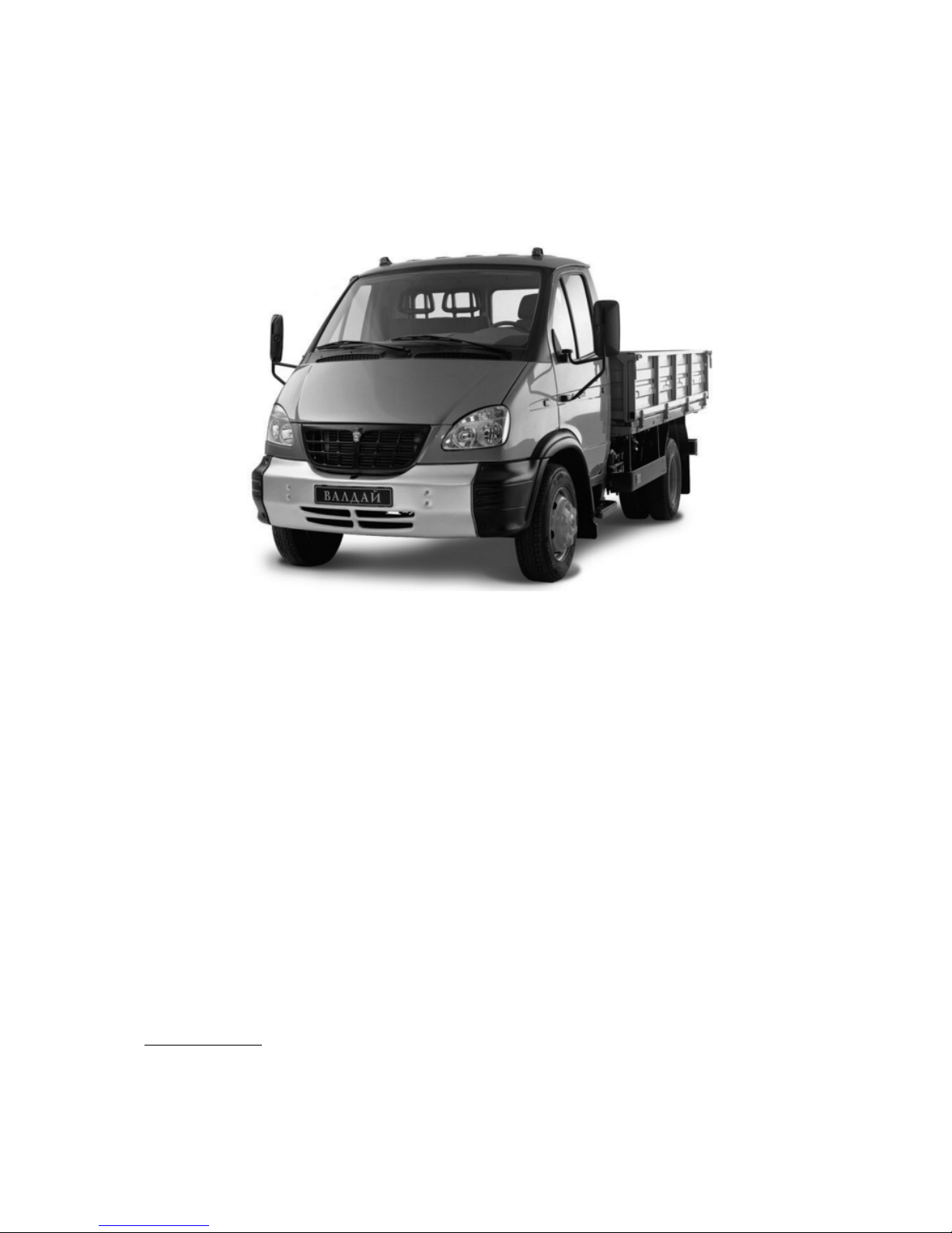
Vehicle Identification Number (VIN) appears on the right frame side
member before the rear spring front bracket (Fig.1.1).
Fig. 1.1. Location of VIN or Chassis Number:
1 — rear spring rear bracket; 2 — frame side member, right; 3 — location of identification number;
4 — rubber restraint cushion
Example of Vehicle Identification Number:
X96 33104050000125, where:
X96 — manufacturer international identification code,
331040 — vehicle index,
5 — model year code,
0000125 — vehicle serial number.
Model year is a period equal on the average to calendar year during which
the vehicles with identical design features are being manufactured.
Chassis identification number is marked on the right side member of the
frame of cargo body vehicles intended for supplying to other plants for manu
facturing special vehicles (Fig. 1.1).
Example of Chassis Number:
33104050000125, where:
331040 — chassis index,
5 — model year code,
0000125 — chassis order number.
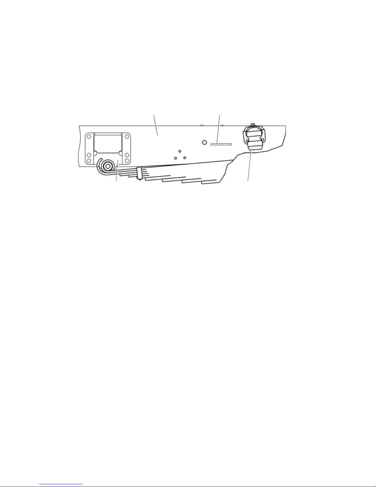
Cab identification number is located under the hood on the front outer
panel, on the left in direction of vehicle movement (see Fig. 1.2, arrow "A"
view).
1 4
3
2
4
Example of Cab (Body) Number:
33104050000125, where:
331040 — cabin index
5 — model year code,
0000125 — cabin serial number.
Fig. 1.2. A — Location of Cab Identification Number
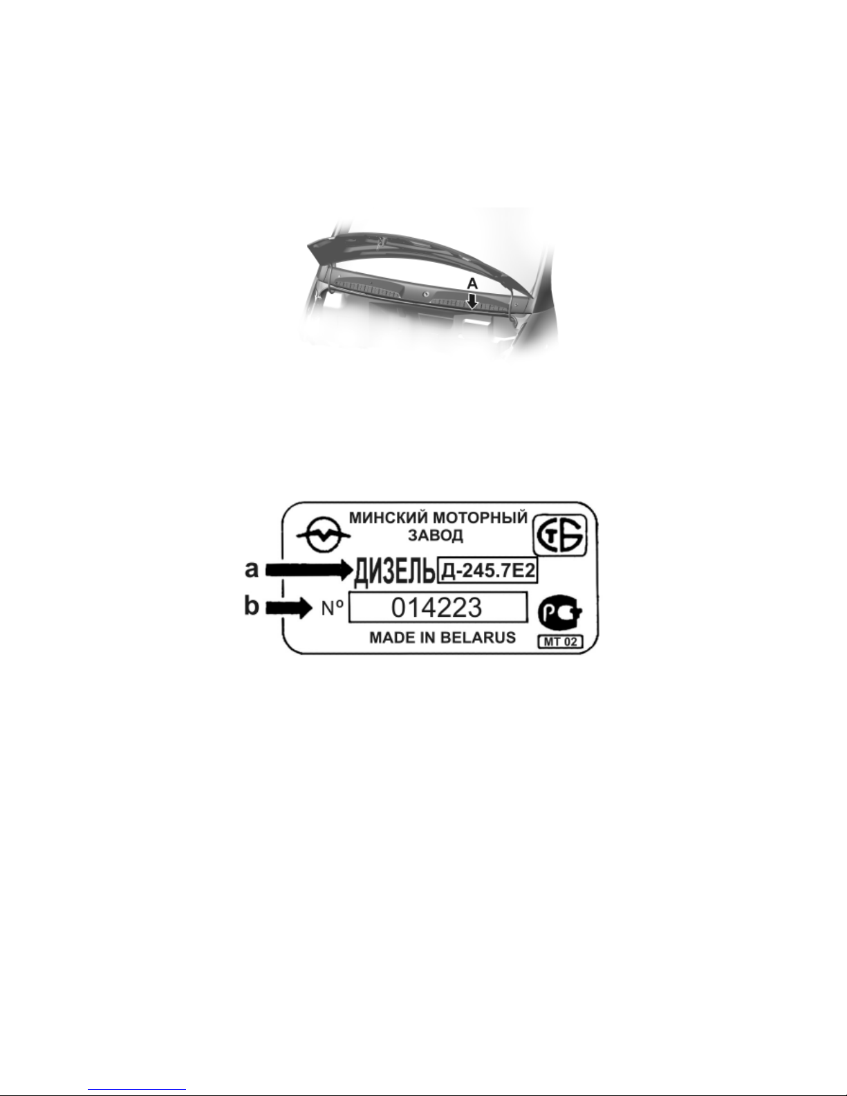
Д245.7 E2 engine number is stamped on the nameplate (Fig. 1.3) located
on the cylinder block in the middle portion on the righthand side.
Fig. 1.3. Д245.7 E2 Engine Nameplate
The nameplate contains the following data:
a — engine index;
b — engine serial number
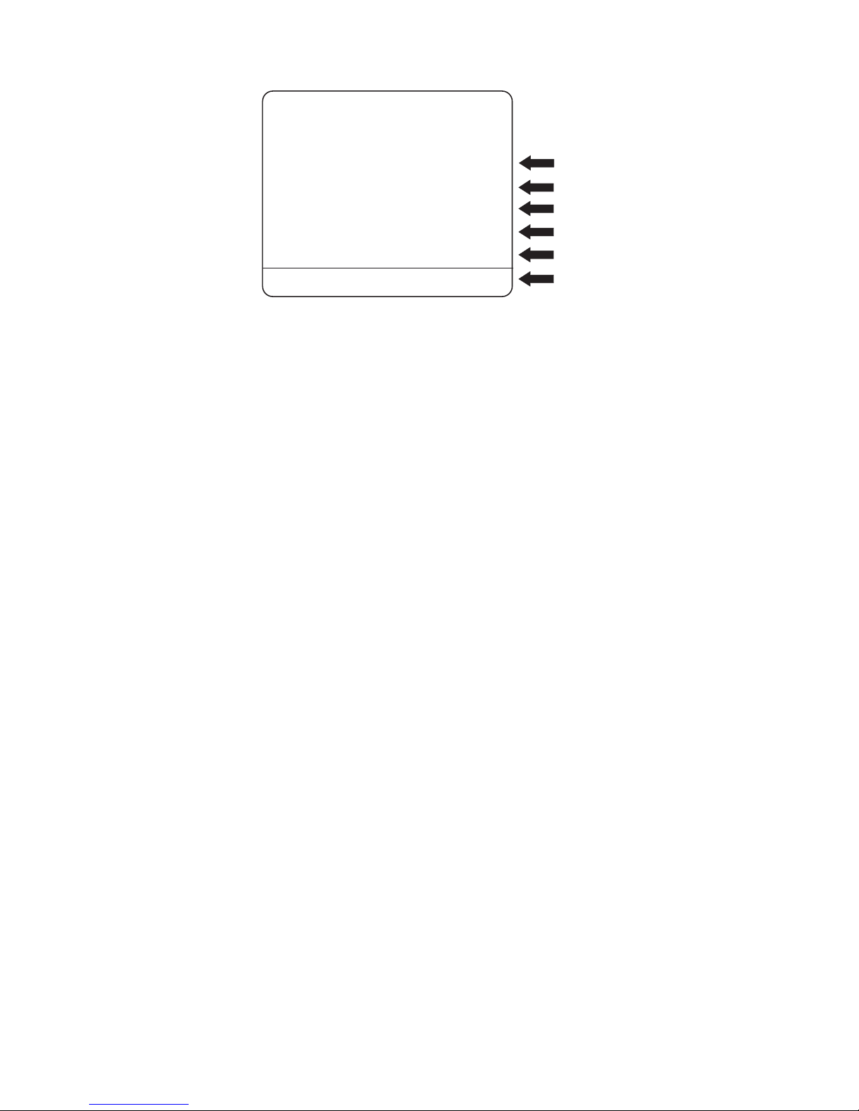
Vehicle identification data also appear on manufacture's plate (Fig. 1.4)
located on the rear pillar of the cab right door.
Chassis, cab and engine numbers refer to the identification data of chassis
and special configuration vehicles for supplying to the other plants for making
their own special vehicles having their own index. Nameplate "GAZ" is not
installed and vehicle identification number does not appear on chassis and the
above vehicles.
5
Fig. 1.4. Manufacture's Plate with Vehicle Identification Data, where:
a — vehicle identification number;
b — gross vehicle weight;
c — gross vehicle weight with trailer;
d — maximum front axle weight;
e — maximum rear axle weight;
f — engine index
2. USEFUL HINTS
1. Procedure of engine starting is described in section 6.2. "Engine Start
ing and Stopping".
After cold engine starting do not run it immediately at high speed because
cold oil passes slowly to rubbing surfaces and they may be got damaged at the
engine high speed.
2. The engine efficient performance and its wear mostly depend on engine
operating temperature. It is necessary to maintain coolant temperature within
the limits of 80–95° C. At the ambient air temperature of 5° C and below in
stall cold weather radiator cover.
3. Do not operate the starter continuously for more than 15 seconds. For
the second attempt of engine starting, allow not less than 30 seconds. Not more
than three engine starting attempts are permissible. Should the engine fail to
fire after these attempts, check the starter power circuits, the starter itself, the
engine fuel system and the storage battery for good condition.
Never move the vehicle using the starter and turn on the starter with the
running engine.
4. After cold engine starting do not run it at high speed. Warm the engine
up at 10001400 rpm. Never drive the vehicle with cold engine. Coolant tem
perature before starting movement should be not less than 40° C.
X96
Д-245.7Е2
33104050140794
7500 кг
-кг
2400 кг
1-
2-
540 кг0
a
b
c
d
e
f
LLC AUTOMOBILE PLANT GAZ““”
ENGINE

6
5. If the engine has been operated at heavy duty cycle let it run for 3 min
utes at idle speed before stopping to decrease smoothly the temperature of tur
bocharger to avoid its premature damage.
6. To prevent damaging of the gearbox when towing the vehicle, discon
nect the propeller shaft flange from the axle drive. Then fix reliably the dis
connected end of the propeller shaft via a wooden block to the vehicle nearest
frame element.
7. Do not eliminate free axial displacement of steering arm pin ball head as
to drag link because the travel equal to 3,4 mm with the shutdown engine is
required for power steering drive proper operation.
8. To avoid dislocating of relative position of the steering gear and steer
ing wheels, never set out the adjustment of the drag link length (except for the
cases specified in given Operating Instructions).
9. To avoid overheating of power steering drive system, do not run the en
gine for a long time at high speed (more than 30 minutes) when the vehicle is
at parking place.
10. With operating engine do not keep the steering wheel turned as far as
it will go for more than 15 sec. because it may cause damage of the power steer
ing pump. Never start the engine with power steering tank empty or insuffi
cient oil level.
11. When the ambient air temperature is below 35° C fill the power steer
ing system with special liquid (see subsection "Lubrication Chart").
12. Watch out for tightness of air pipelines, cylinders and pneumatic valves.
Break of air tightness reduces braking efficiency.
13. To avoid storage batteries failure, timely switch over regulated volt
age level.
14. If any of the red pilot lamps lights up on the instrument cluster or buzzer
operates on the run, stop the vehicle, detect and eliminate the trouble.
15. The brake pads are to be replaced at service stations only.
3. SAFETY PRECAUTION RULES
Strictly follow the safety precaution rules during vehicle operation.
Never warm up the engine in the enclosed space. The engine exhaust gases
contain toxic end product of fuel combustion, monoxide carbon including (gas
without fume and color), which, when inhaling, causes severe intoxication and
it may even lead to fatal case. It is also not recommended to turn on the pas
senger compartment ventilation at parking place with the operating engine.

7
4. SPECIFICATIONS
4.1. GENERAL DATA
Vehicle model GAZ33104 GAZ331041 GAZ331043
Vehicle type Biaxial, cargo, with rear axle drive
Vehicle capacity, kg:
— with cargo body without canvas top 3605 3445 3150
— with cargo body and with canvas top 3500 3330 3045
Vehicle gross mass, kg 7400 7400 7400
Vehicle kerb mass, kg:
— with cargo body without canvas top 3500 3730 3800
— with cargo body and with canvas top 3605 3845 3905
Overall dimensions, mm
— length 6050 7565 6770
— width (over mirrors) 2643 2643 2643
— height (over cabin, unladen) 2260 2260 2265
— height (over canvas top, unladen) 3060 3060 3060
Wheelbase, mm 3310 4000 4000
Front wheels track, mm 1740 1740 1740
Rear wheels track (between centres of twin tyres),
mm 1701 1701 1701
Ground clearance, fully laden, mm 177 177 177
Minimum turning radius (front outer track), not
more, m 6,4 7,7 7,7
Maximum speed with full load without trailer on
flat, smooth highway, km/h 95 95 95
Fuel consumption1) when running with constant
speed, l/100km:
— 60 km/h 13,5 13,5 13,5
— 80 km/h 18,0 18,0 18,0
Overhang angles (fully laden), deg.:
— front 27 27 27
— rear 14 10 14
Maximum climable gradient for fully laden vehicle,
% (degree) 25 (14) 25 (14) 25 (14)
Cargo body loading height, mm 1070 1070 1070
4.2. ENGINE AND ITS SYSTEMS
Model D245.7 E2
Type Diesel, 4stroke, with turbocharger, with
supercharged air cooling, liquid cooling
Number of cylinders and their arrangement 4, vertical inline
Cylinders firing order 1—3—4—2
Direction of crankshaft rotation right
1) The fuel consumption specified is not considered to be a rate but serve only for determining
of vehicle technical state.

8
Cylinder bore and piston stroke, mm 110x125
Displacement, l 4.75
Compression ratio 17
Rated power, net, kW (h.p.), not less:
at 2400 min1 engine speed 86.7 (117.2)
Maximum torque, net, N•m (kgf•m):
at 13001600 min1 engine speed 413 (42.1)
Minimum engine idle speed, min
1
800
Maximum idle speed limited by governor, min1,
not more 2600
Ventilation system open
Fuel injection pump Inline, 4plunger, valve type, 7732005
(ЯЗТА) with full range rpm governor and
booster fuel pump
Booster fuel pump Plunger type, for manual and automatic
fuel priming
Injectors ЯЗДА 455.111201050, closed type;
injection point pressure 23,5+1.2MPa
(230 kgf/cm2)
Fuel filters:
— coarse filter Gravitation filter with gauze element
— fine filter With paper renewable filter element
Oil system Combined: under pressure and spraying
Oil cooler Fullflow, constantly operating
Oil filter Fullflow, with renewable filter element
Cooling system Liquid, closed, with forced coolant circula
tion, with expansion tank
Supercharging system Gas turbine, with one turbocharger C14
with radial centripetal turbine, centrifugal
compressor and air cooler of supercharging
air of secondary surface type
4.3. TRANSMISSION
Clutch Singleplate, dry, friction type, with torque
vibration damper on driven plate. With di
aphragm pressure spring. With hydraulic
drive
Gearbox Mechanical, 5speed, with constant gear
mesh, with synchromesh unit on II and III,
IV and V gears
transmission ratios:
— 1st gear 6.555
— 2nd gear 3.933
— 3d gear 2.376
— 4th gear 1.442
— 5th gear 1.000
— reverse gear 5.735
Cardan drive Two open type divided propeller shafts,
three universal joints on needle bearings

9
Final drive Bevel, hypoid type
— transmission ratio 3.417
Differential Bevel, geartype
Axle shafts Full floating
4.4. RUNNING GEAR
Frame Stamped, riveted
Wheels Disk type, with 6,00x17,5 rim
Tires Pneumatic, radial, size 215/75R17,5
Front wheel geometry:
— camber Max. 1°
— pivot transverse inclination 8°
— lengthwise inclination of king pin 5°
— toein (of every wheel to vehicle longitudinal
axis) 7"±3"
Springs Four, longitudinal, semielliptic with ad
ditional springs in rear suspension
Shock absorbers Hydraulic, telescopic, dual acting. Mount
ed on the front axle
4.5. STEERING SYSTEM
Type of steering gear Screwball nut
— transmission ratio 19.8 (in the middle position)
Power steering Hydraulic, integrated, built in steering gear.
Power steering pump is a geartype. НШ14
Steering column Height and tilt adjustable
4.6. BRAKE SYSTEM
Service brake system Doublecircuit, with pneumatic drive
Brake gears Disk type
Emergency brake system Each circuit of service brake system
Parking brake system With pneumatic drive of brake chambers
with spring energy accumulators installed
on rear wheel disk brakes
4.7. ELECTRICAL EQUIPMENT
Wiring system Single wire. Negative terminals are connect
ed to vehicle frame
Rated voltage, V 12
Alternator A/C, with builtin voltage regulator and
rectifier block, 1631.370110
Storage battery Two (6CT 110A)
Starter AZS 3385"Искра"
Headlamps 62.371119

10
Turn indicator repeaters 5302.3726000 or 112.03.30.00.00001
Front marker lights 265.3712
Rear lights 7442.3716.00011 or 8502.371601
Side marker light 4472.3731
Headlamp aiming device control unit БУК24 or 281.3769 or 231.3769
Engine control switch 2126370401050 or 2108370401080
Windshield wiper 60.5205 or 70.5205
Windshield washer 1202.5208, 1102.5208
Horns 22.3721/221.3721
4.8. CABIN AND CARGO BODY
Cabin Metal, three— or sixseat
Cargo body Metal, with rear flap and body sides
Cargo body dimensions (inner), mm: GAZ33104 GAZ331041 GAZ331043
— length 3494 5000 3494
— width 2176 2176 2176
— body side height 518 518 518
4.9. MAIN ADJUSTMENT AND CHECKING DATA
Clearance between valve stems and rocking levers
on cold engine, mm
— intake 0,25
— exhaust 0,45
Oil pressure (at oil temperature of 80–85° C), kPa
(kgf/cm2):
— at rated engine speed 2400 min
1
250–350 (2.5–3.5)
— at minimum idle speed 80 (0.8)
Rated engine coolant temperature, °C 80–95
Minimum engine idle speed, min
1
800
Variable voltage, V 13.3–14.9
Fan and alternator belts sag under 4 daN (4 kgf), mm 12–17
Clutch pedal free travel, mm 10–30
Clutch pedal full travel, mm 190
Brake pedal free travel, mm 9–16
Total play of steering wheel in the position corres
ponding to vehicle straightforward run with run
ning engine, deg., not more 101); 25
Tire air pressure, kPa (kgf/cm2)
— front wheels 530
+10
(5.4
+0.1
)
— rear wheels 620
+10
(6.3
+0.1
)
1) For the vehicle within warranty period.
+0,05
–0,10
+0,05
–0,10
11
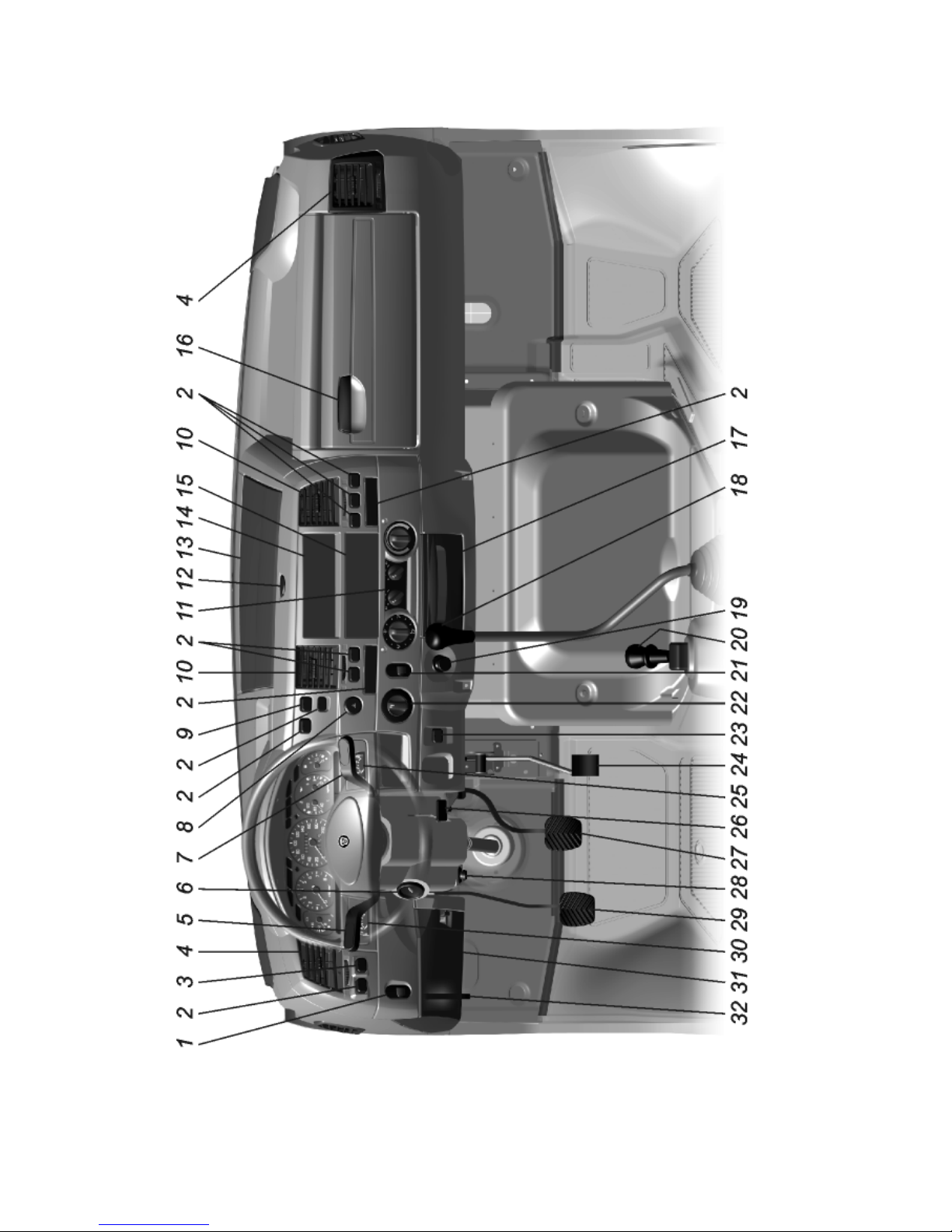
5. CONTROLS AND INSTRUMENTS
Fig. 5.1. Controls
12
Positions of controls are given in fig. 5.1.
1 — headlamp aiming device control knob depending on vehicle loading
(see subsection 8.5).
2 — plugs.
3 — warning lamps condition checkup switch.
4 — side ventilation grids.
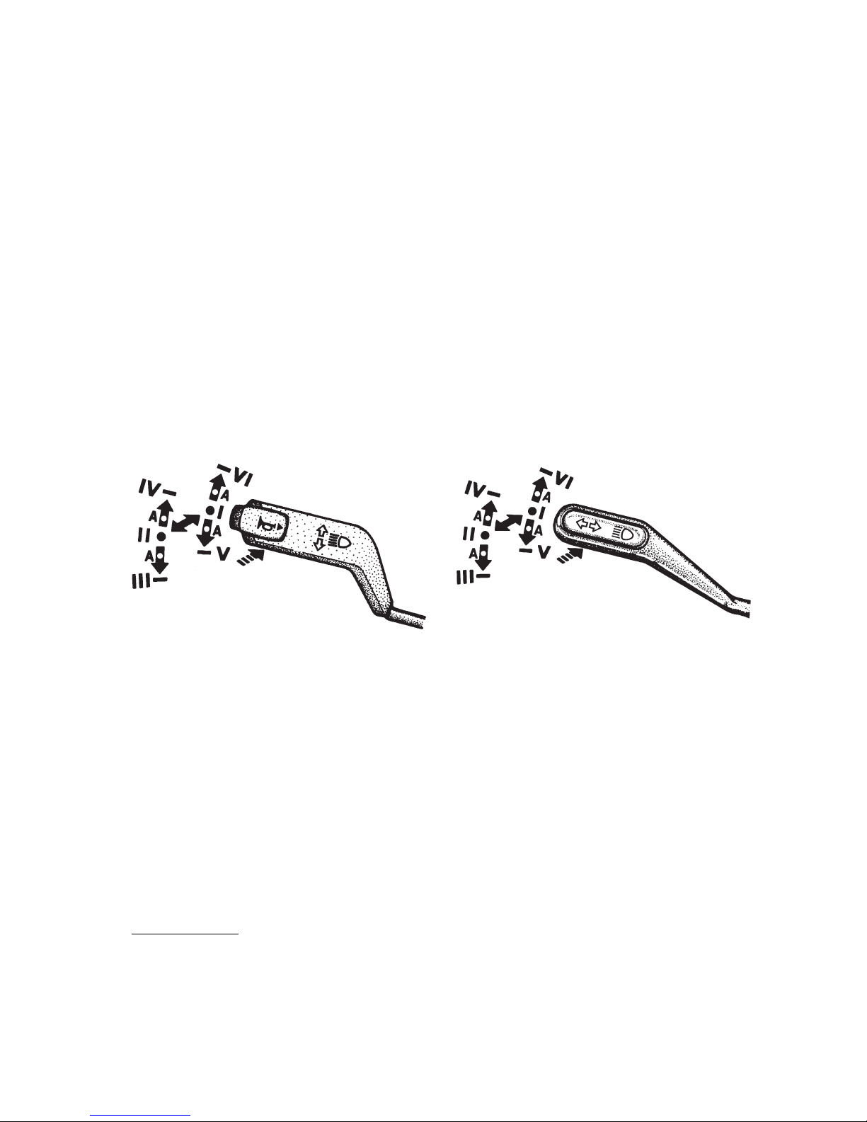
5 — turn indicators, dimmer and horn1) switch lever. The switch lever
has six fixed positions (from I to VI) and four nonfixed positions "A" (fig. 5.2
and 5.3).
If the lever is in position I, and master light switch knob 22 — in position
II, the lower beam is on. When the lever is moved to position II upper beam is
switched on and blue indicator lights up.
Pulling the lever repeatedly from position I along the steering column (non
fixed position) switches on headlamp upper beam for a short time. Depressing
the switch lever button (in any position of the lever) turns on the horn1) (non
fixed position) — see fig. 5.2.
1) On some of the vehicles the horn is switched on by means of windshield wiper and washer
control lever (see Fig. 5.6).
Fig. 5.3. Turn indicator and dimmer
switch lever (without horn)
Fig. 5.2. Turn indicator and dimmer
switch lever (with horn)
To operate turn indicators move the lever from positions I or II up to posi
tions VI or IV (right turn) or down to positions V or III (left turn). A green
warning light comes on flashing on the instrument cluster.
After the turn is completed the switch lever is automatically returned to
position I or II. To switch on turn indicators momentarily shift the switch le
ver to suitable "A" nonfixed position. When released the lever returns to po
sition I or II.
6 — engine control, starter and antitheft device switch.The key posi
tions are given in fig. 5.4:
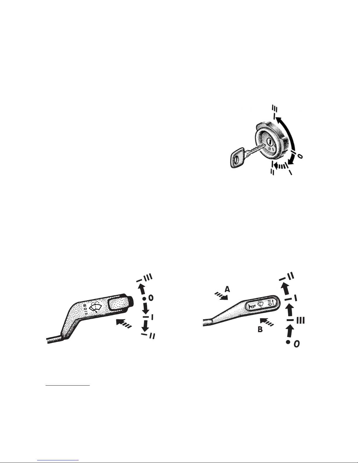
13
0 — all Off, the key cannot be pulled out, antitheft device is not engaged;
I — engine control switch is On; the key cannot be pulled out;
II — engine control switch and starter are On; the key cannot be pulled out;
III — engine control switch is Off; when the key is withdrawn, the anti
theft device is engaged.
To release the antitheft device fit the key, then gently swinging the steer
ing wheel to both sides turn the key to position 0.
Fig. 5.4. Engine control, starter and antitheft
device switch.
7 — windshield wiper, washer and horn 1) switch lever.
The positions of the lever (fig. 5.5 and 5.6):
0 — windshield wiper is OFF;
I — low speed of windshield wiper;
II — high speed of windshield wiper;
III — intermittent operation of windshield wiper.
In case the control lever is not equipped with horn switch (fig. 5.5), to
turn on windshield wiper and washer momentarily pull the lever (in the direc
tion of the arrow) from position 0.
Fig. 5.6. Windshield wiper and
washer lever positions (with horn)
Fig. 5.5. Windshield wiper and
washer lever positions (without horn)
1) On some of the vehicles the horn is turned on by turn indicators and dimmer switch lever
(see Fig. 5.2).
14
In case the control lever is equipped with horn switch (fig. 5.6), to turn on
windshield wiper and washer momentarily push the lever from position 0 in
the direction of arrow "A" and to turn on the horn pull the lever (from any
position) in the direction of arrow "B".
Windshield washer can be also switched on from all lever positions. Wind
shield wiper operates only when the engine control switch is on.
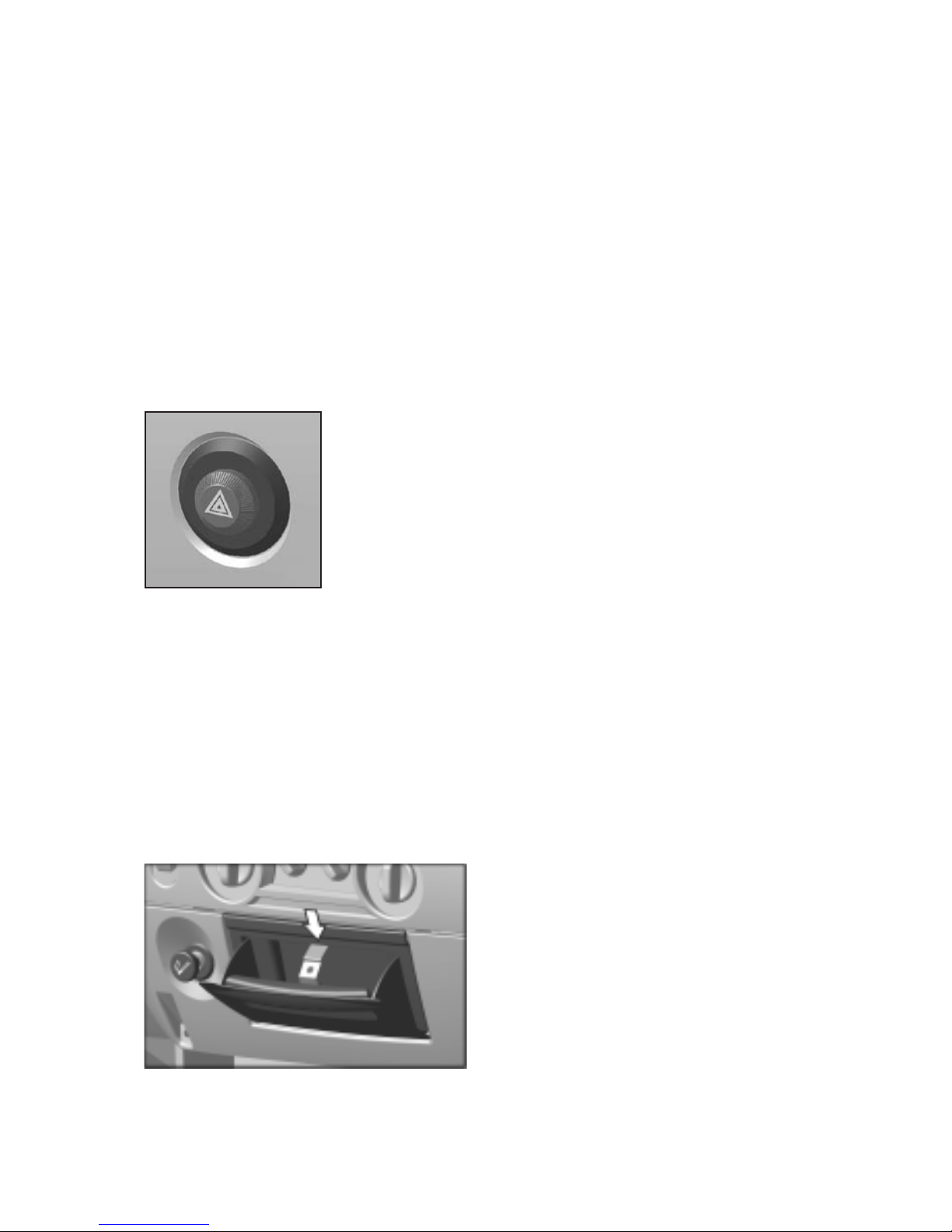
8 — emergency flasher warning system button switch. When in switched
on position all turn indicator bulbs and red bulb inside the button switch
(fig. 5.7) are flashing simultaneously.
Emergency flasher warning system should be switched on in case of vehi
cle accidental stop in order to inform other drivers and maintenance services
about stationary vehicle on the roadway.
Fig. 5.7. Emergency flasher warning system button
switch.
9 — rear row seats dome lamp switch of the cab (for vehicles with two
rows of seats).
10 — central ventilation grids.
11 — heating and ventilation control panel.
12 — lock button for documents box cover.
13 — documents compartment cover.
14 — space for radio set/cassette player.
15 — plug.
16 — glove box lock handle.
17 — ashtray. Removal of ashtray is shown in fig. 5.8.
Fig. 5.8. Ashtray
15
To empty the ashtray pull it, push spring catcher upwards and remove the
ashtray from its slot. Fit the ashtray back liftingup the spring catcher.
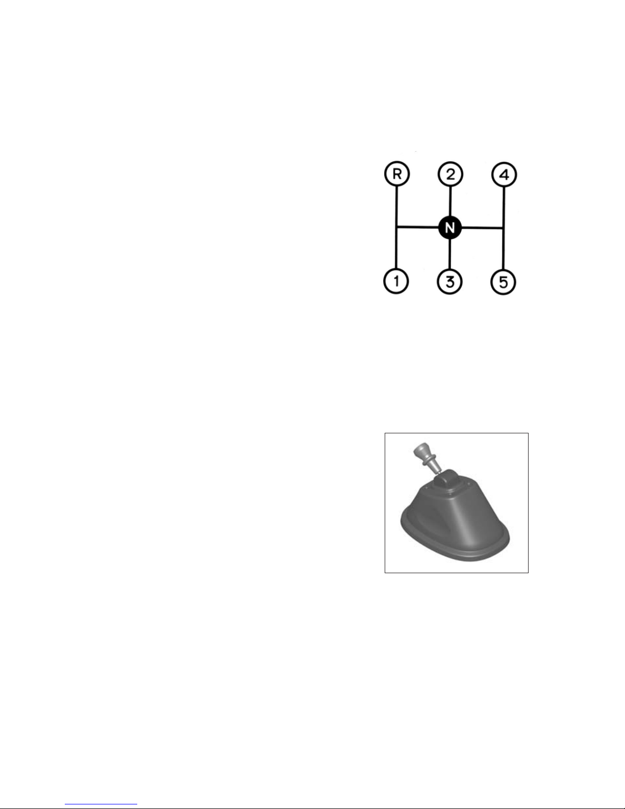
18 — gearbox lever.
Engage reverse gear only after full stop of the vehicle. When reverse gear
is engaged the backing light goes on in the tail lamps.
Fig.5.9. Changeover layout:
19 — cigarette lighter. To use the lighter, push its handle and release it.
The lighter kickout with a click means that the coil is hot. Do not reuse the
lighter sooner that in 30 s.
20 — parking brake lever. For braking the vehicle pull the brake control
lever up. If the engine control switch is on warning lamp 9 (fig. 5.14) is flash
ing on the instrument cluster. For releasing the brake pull up the control lever
lock coupling. With the brake released the warning lamp goes out.
Fig. 5.10. Parking brake lever
21 — instrument lighting control knob.
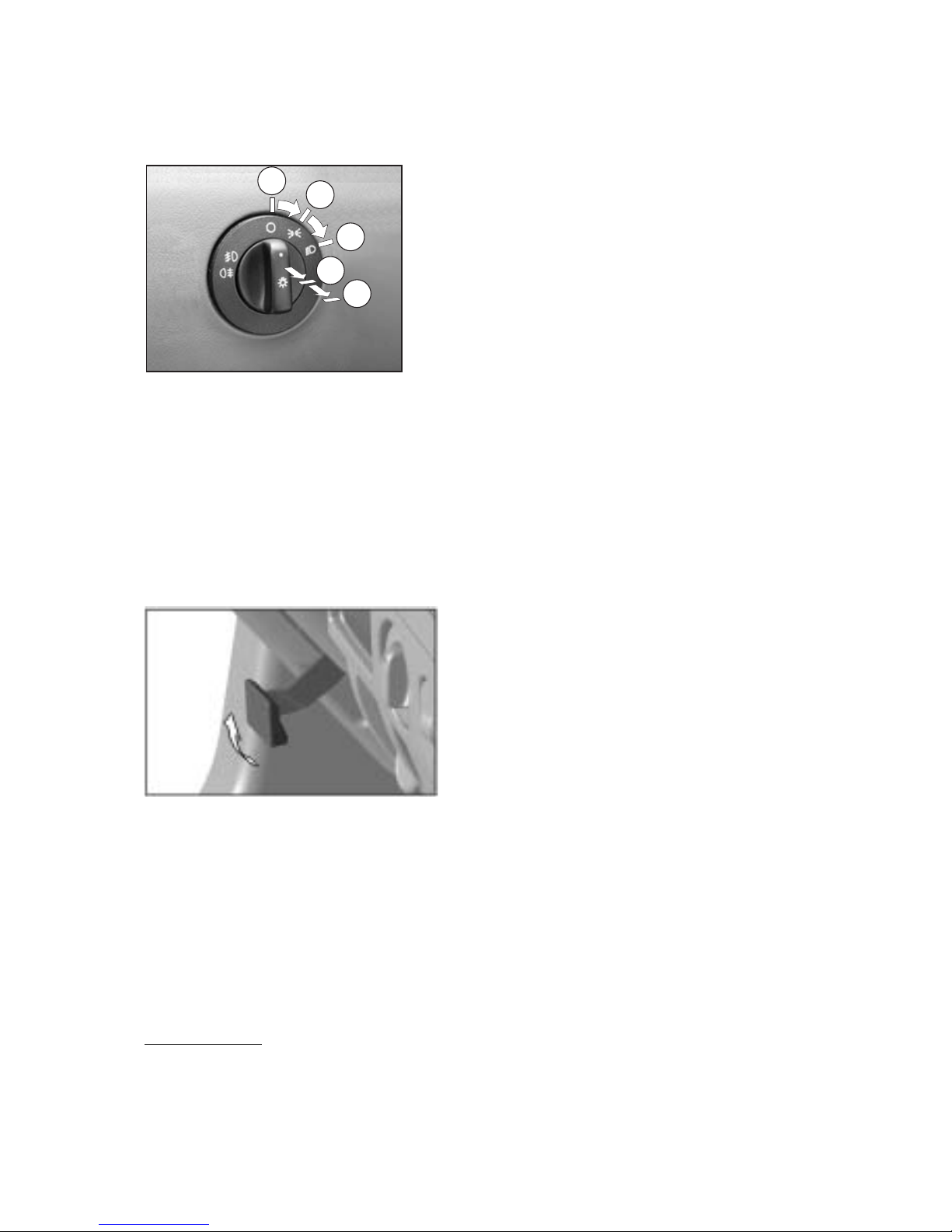
22 — master light switch. The switch has five fixed positions (fig. 5.11):
0 — all external lighting is OFF.
I — clearance lights, instrument cluster lighting, rear license plate lamp
and some electrical equipment controls lighting is ON.
II — additionally upper or lower beam is ON depending on the position of
turn indicators and dimmer switch lever (position I or II correspondingly).
16
III — additionally (from position I or II) front fog lamps1) are ON.
IV — additionally (from position III) rear fog light is ON.
1) Mounted on some of the vehicles
Fig. 5.11. Positions of master light switch
handle.
0
I
II
III
IV
23 — ABS diagnostics button.
24 — accelerator pedal.
25 — brakes rear circuit pressure gauge.
26 — steering column adjustment control lever (fig. 5.12). Pulling the
lever and moving it upwards (within the limits of 90°) results in releasing of
the steering column. After that the steering wheel can be set in the handy po
sition for a driver and locked in this position by setting the lever to the initial
position.
Fig. 5.12. Steering column adjustment
control lever.
27 — service brake pedal.
28 — storage battery remote button switch.
29 — clutch pedal.
30 — brakes front circuit pressure gauge.
31 — fuse blocks.
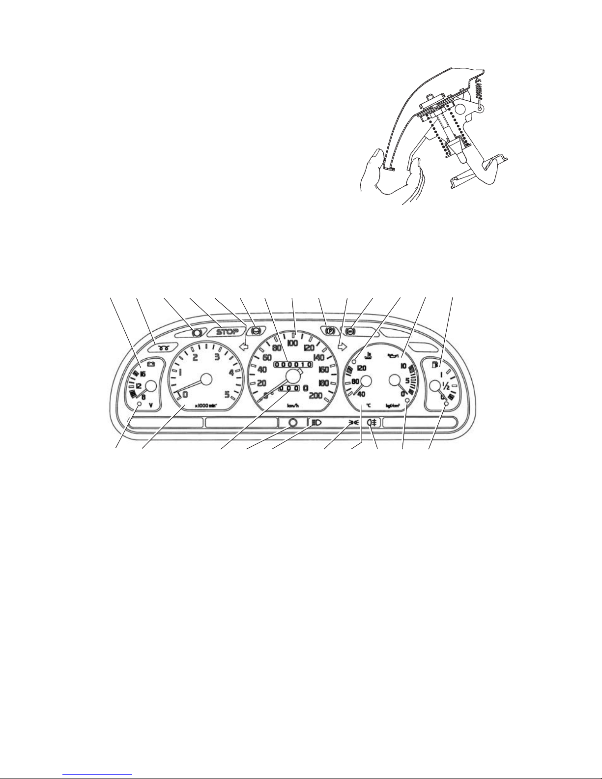
32 — hood release lever. To open the hood pull lock handle to release the
catch of the lock and open the hood slightly, then push the handle back home.
17
To open the hood completely, move aside the latch mounted on the lower
front edge of the hood (fig. 5.13).
Arrangement of instruments is shown in Fig. 5.14.
Fig. 5.13. Releasing of hood latch.
Fig. 5.14. Instrument cluster.
1234567891011121314
15161718202122
192324
1. Voltmeter.
2. Warning lamp (orange) of glow plugs cuttingin.
3. Warning lamp of brake linings wear.
4. Warning lamp (red) "STOP".
5. Warning lamp (green) of left turn indicators.
6. Reserve warning lamp.
7. Total distance counter.
8. Speedometer.
9. Warning lamp (red) of parking brake engagement.
Starts flashing after turning on the engine control switch, when the park
ing brake is engaged.
 Loading...