


Zislin SG, MOZOHIN NG, PELYUSHENKO OI, CHERNOMASHENTSEV AI, Yakubovich IE CARS
GAZ-69 and GAZ-69A
Design description, ADJUSTMENT AND CARE
GORKOVSKAYA BOOK PUBLISHING 1956 The book describes the construction of car -
Lei GAZ-69 and GAZ-69A, and the main indication by adjusting the individual mechanisms and the care of aggregaghats.
The book is designed for personnel involved in
Exploitation of GAZ-69 and GAZ-69A (vodi - makers and engineers), and can serve as a tool For teachers and students of driving schools and technology -
mov.
Chief Editor
Designer Automobile them. Molotov N. Borisov
The request for the expulsion of the book, contact: Mr. Gorky Str. Sverdlov, 12, Shop Knigotorga number 1 "Book-mail"
PREFACE
GAZ-69 is a car-road-drive Th - tyre-wheel drive (4X4).
This car has successfully replaced in the national economy car GAZ-67B. Being single tipnym car with GAZ-67B, it surpasses it in every respect.
In order to best meet the diverse needs of the economy and the population automobile GAZ-69 is available with two types of bodies: eight-(utility) and five-seater (passenger).
Chassis of the car, with the exception of the rear springs and gasoline tanks, the same for both bodies. Rational layout would double the capacity of the GAZ-69 in comparison with the automobile GAZ67B (8 people instead of 4 persons).
Weight vehicles, falls on one person, is (in kg): for eight-car GAZ-69 190
for a five-seater car GAZ-69A 307 Car GAZ-67B 330
Thus, despite the significant increase in the size of the new eight-car and use of more nodes, its own weight, which falls on a passenger, a 57% less than the GAZ-67B.
GAZ-69 can pull a trailer weighing 850 kg, well overcomes the sand, marsh and snow-covered stretches of road, rises (over 20 ° with the trailer and more than 30 ° without a trailer) and goes on fords a depth of up to 60 cm.
Payload GAZ-69 is 650 kg, while the GAZ-67B only 400 kg.
GAZ-69 has much better efficiency compared with the vehicle GAZ 67B. Fuel consumption per tonkilometre by car GAZ-69 on 65 - 80% less than the car GAZ-67B.
GAZ-69 has a soft suspension four longitudinal semi elliptical springs and the tyre double acting hydraulic shock absorber.
The car can reach a maximum speed of 90 km / h without a trailer and up to 80 km / h with Pricapom. It should also be noted that the GAZ-69 (compared with the GAZ-67B) has two or three times in elevated wear resistance of parts and assemblies, improved design of units and the best sustainity (due to the low centre of gravity).
GAZ-69 has a greater capacity and comfort of the body, has easily governance.
PRINCIPLES FOR GOOD GOVERNANCE and good access to the unit for servicing and repair. Past state tests showed that the GAZ-69 and GAZ-69A (pyatimest -HYDRATED) fully satisfy the requirements for passenger cars increased Pass conductivity.
GAZ-69 is widely used in collective and state farms, MTS, construction, trade network, postal service (especially in bad road conditions). In the car GAZ-69 used in full (or with slight changes) units and aggregates GAZ. From car M-20 used: engine, clutch, gearbox, cardan va ly, hinges steering rods, the
main transmission and differential, the master cylinder hydraulic brakes, foot brake, shock absorbers, ignition device and the heater body. From car GAZ-51 used: steering wheel, a lamp starting heater, lights and podfar - Niki, tail lights, light switch, the petrol tank. Steering gear (except the steering shaft and column) taken from the car ZIM. The book describes the design of cars GAZ-69 and GAZ69A and are some basic guidelines for their operation and maintenance of individual units.
The book is designed for personnel involved in the operation of GAZ-69, and in the first instance, red drivers of these vehicles, and may also serve as a teaching tool in driving schools.
Chapter I |
|
Car specifications |
|
GENERAL DATA |
|
The number of places, including the driver, and load |
|
1. For car GAZ-69: 8 people or 2 persons and 500 kg of cargo. |
|
2. For GAZ-69A: 5 people and 50 kg cargo in the trunk. |
|
Dimensions (rounded) in mm: |
|
Length |
3850 |
width for the GAZ-69 and GAZ-69A, with a spare wheel removed |
1750 |
width of the GAZ-69 with installed spare wheel |
1850 |
height of an awning in the unloaded state for GAZ-69 |
2030 |
same for the GAZ-69A |
1920 |
Base (distance between axles) |
2300 |
Track front and rear wheels (in the plane of the road) |
1440 |
The lowest point of the car under load: |
|
Carter front axle |
210 |
Rear axle |
210 |
crossbar transfer case |
310 |
Angles patency (with load): |
|
Front |
45 ° |
Rear |
35 ° |
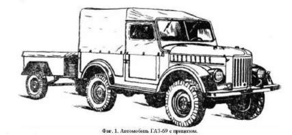
Fig. 1. GAZ-69 with a trailer. |
|
Minimum turning radius in m: the trail of the outer front wheel |
6 |
on the front bumper |
6.5 |
The highest rate with normal load (horizontal smooth sections of highway without a trailer) 90 km / h.
Weight distribution and the total weight of the car GAZ-69 in kg: |
Unlade |
Full load |
front axle |
860 |
940 |
rear axle |
665 |
1235 |
total weight of the car |
1525 |
2175 |
Weight distribution and the total weight of the GAZ-69A in kg: |
Unlade |
Full load |
front axle |
820 |
925 |
rear axle |
715 |
1035 |
total weight of the car |
1535 |
1960 |
Notes: |
|
|
1.In the unladen weight of the car include the weight of fuel, water, grease, set the driver's instrumentment and spare wheel.
2.The payload for the GAZ-69 adopted: 2 people on front seats and 500 kg of cargo.
3.The payload for the GAZ-69A, adopted by: 5 people and 50 kg of cargo in the trunk.
4.Weight allowance of one man is 75 kg.
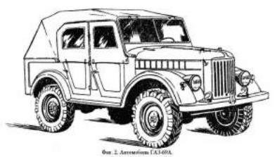
Fig. 2. GAZ-69A. |
|
|
Allowable weight trailer with load |
850 kg |
|
Angle of ascent for the car on solid ground: |
|
|
a) without a trailer |
|
30 ° |
b) a trailer weighing up to 850 kg |
20 ° |
|
ENGINE |
|
|
Engine Type 4-stroke, gasoline, carburettor |
|
|
Cylinders 4 |
|
|
Cylinder capacity |
2,112 |
|
Compression ratio |
6,2 - 6,5 |
|
Maximum power 55 hp. with. at 3600 rpm |
|
|
Maximum torque 12.7 kgm |
|
|
Minimum specific fuel consumption at full throttle (in it t - |
Zone 2200 - 2400 rpm) |
|
265 g / elsch |
|
|
Fuel Auto. petrol A-70 GOST 2084-51 (70 octane)
Note:
These external characteristics are given to normal conditions (760 mm Hg. Art. And 15 ° C) and otno reduction the engines passed the bedding on the stand for 50 hours.
Upon removal of the external characteristics of the engine is tested without the generator, fan and water pump. As fuel is gasoline octane 70.
CHASSIS Strength Dry, single plate Transmission
Two-pass, with three forward gears and one back Ratios:
1-gear 3.115
2 gear 1.772
3rd transfer 1.000 reverse 3.738
Transfer Case Gear, has two transmissions with allow exact numbers 1,15 and 2,78
Drive shafts
Driveshaft’s three: intermediate, posterior ny and the front Alignment of front wheel
Camber of the wheels 1 ° 30 '.
The angle of lateral inclination kingpin 5 °.
The angle of inclination of the lower end of the kingpin 3 °. Ret wheels 1,5 - 3 mm
The main gear front and rear axles Conical, with spiral tooth, allo - the exact number of 5,125 Type semi axes Flanged, fully unloaded
Transmission pushing efforts and the perception of reactive torque ment of both bridges Springs Suspension Vehicle Leaf, the four longitudinal poluel lipticheskih springs, running joint but with four hydraulic piston double-acting shock absorbers
Spare wheel: car GAZ-69 On the bracket on the left side Car GAZ-69A On the bracket in the trunk Tires Low pressure the size of 6,50 - 16. "Protec tor equipped with cleats
Type of gear and gear ratio Globoidalny worm with a double roller. Gear ratio 18,2:1 (average)
Type brakes treadle
Drum on all 4 wheels drive Hydraulically from the pedal Type brakes with manual transmission
Block with a drum. Located on transfer case behind. Drive mechanical Czech and rope from the lever
ELECTRICAL
Power voltage (nominal) 12 volts
Generator Type G20, 12 volt, 18 amp, shunt, pabot with voltage-and lim ranichitelem current type PP12 and PP20-A-B
Battery Type 6-CT-54, 12 volt, 54 ampere capacity hours
Coil Type B21 or B1 with an additional resistance tion is automatically turned off when starting the engine starter
Distributor Type P23, with centrifugal and vacuum regulyatorom ignition timing and octane - proofreader
Spark plugs Type M12U, with the thread 18 mm Starter Type St20, mechanically forced inclusion Headlamps
Type OP2-A2, 2 pcs. Two tiers of windows - with neighbours and distant light Signal Type S56-B, an electric vibrator
Fuses
Heat, such as WP2-B in the lighting circuit, melting in the signal chain and the rear lights and devices Wiring
Single-wire, plus the battery batteries connected with the mass of the car
SPECIAL EQUIPMENT
Starting Heater Thermo siphon working on solder Lamp Tank for oil
By car GAZ-69 is installed in a box with right side, front under the rear seat it. By car GAZ-69A is installed in trunk
BODY
Body of GAZ-69
All-metal, open, vosmime - stny, two-door with rear folding bur - Volume
Body of GAZ-69A All-metal, open, pyatimest - HYDRATED, four-door with a trunk in the rear part Windscreen
Rotating in a special frame.
Frame with the windshield can be posited on the hood
FILLING CAPACITIES AND STANDARDS IN LITRES
Petrol tanks GAZ-69: major 48 (10.6 gallons) additional 27 (5.9 gallons) Petrol tank car GAZ-69A (a) 60 (13.2 gallons)
Cooling 12
Engine lubrication system (including filters for coarse and fine filter and oil cooler) 5.5
Inhaler 0.25 Carter gearbox 0.8
Carter, transfer case 1.1 Carters Bridge (each) 0.75 Carter steering 0.33 Damper (each) 0.145 Hydraulic Brake System 0.4 Spare tank for oil 6
DATA FOR adjustment
Gaps between the pushers and the valves (in mm) for cold start: at the intake valves 0.23

from exhaust valves 0.28 |
|
|
|
|
Free running clutch pedal with the engine off (in mm) |
38 - 45 |
|
|
|
Free lift the brake pedal (in mm) 8 - 14 |
|
|
|
|
The normal deflection of the fan belt by pressing between the pulleys |
(mm) |
10 - 15 |
||
The gap between the contacts of the breaker (in mm) |
0,35 - 0,45 |
|
|
|
The gap between the electrodes of spark plugs (in mm) 0,7 - 0,8 |
|
|
||
The normal water temperature in the cooling system (heat treatment) |
80 - 90 |
C |
||
Inflation pressure (in kg/cm2): |
|
|
|
|
front wheels |
2 |
|
|
|
rear wheels |
2.2 |
|
|
|
Engine oil pressure (for control, not subject to adjustment) 2 - 4 kg / cm 2 - At the speed of the vehicle 45 km / h on a straight transfer; idling - 1 (rounded).
CONTROLS AND CONTROL DEVICES
Location of controls and monitoring devices car shown in FIG. 3 and 4. Pedal 25 clutch, pedal 24 brake and gear shift lever 18 are in accordance with the obscheprinyatym standard. The right of the brake pedal is the throttle pedal 22, and the left of the pedal-laced
PRINCIPLES FOR GOOD GOVERNANCE - 26 button footswitch light.
In the center of the steering wheel 1 is placed button 3 beep. To activate the starter is pedal 19. At the feet of the driver, on the floor on the right, set off switch 23 gasoline, which has three positive zheniya handle: handle faucet is turned forward - turn off the tap handle is turned to the left - including OS - thus a key tank, the handle is turned to the right - included an additional tank. Between the front seats of Ras laid levers: 21 - inclusion of the front axle and 20 - the transfer case (demultiplika - Torr). The provisions of the heads of these instruments are shown on the nameplate located on the dashboard. Lever 17 central (hand) brake lever is located to the right gear.
Note.
By car GAZ-69A, put a gasoline tank and three-way stopcock 23 no.
On the dashboard LOCATED:
1. The combination of devices 5, consisting of the speedometer 35, ammeter 38, the pointer 31 levels of benzo - mainly on the tank, thermometer 36, showing the temperature of coolant in the head tsilind - ditch, and a manometer 33, showing the oil pressure in lubricating system of engine. Combined devices there are also: two light bulbs 34 lighting devices, the indicator lamp 37 (red), show - schaya inclusion of main beam, and the pilot light 32 (green) illuminates when the temperature coolant in the radiator within 92 - 98 ° C. If ignition of the light bulbs need to find out the reason that caused the increase in temperature, remove it and only then continue. When you turn off the ignition devices (except the ammeter) are switched off. In this hands-level pointers nya petrol gauge and stop at zero scale, and the arrow pointer-temperature terminated by Vaeth left dividing 100 ° C.
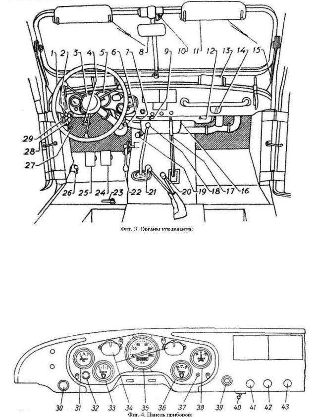
Fig. 3. Controls:
1 - steering wheel, 2 - Latch windshield, 3 - button signal, 4 - lever radiator shutter, 5 - a combination of devices, 6 - lever hatch cover ventilation, 7 - button lighting the fuse, 8 - mirror, 9 - switch lighting devices 10 - wiper switch, 11 - protivosolnechnyh shield, 12 - switch lamp, 13 - directional airflow windshield, 14 - lamp, 15 - coulisse windscreen, 16 - heater, 17 - a central brake lever, 18 - lever gear, 19 - pedal starter, 20 - the transfer case lever, 21 - lever inclusion of the front axle, 22 - pedal Droß - lodging, 23 - Three-way valve (on the car GAZ-69A or put), 24 - brakes, 25 - clutch pedal 26 - button footswitch switch the light 27 - switch turning lights, 28 - fuse block, 29 - socket.
Fig. 4. Dashboard:
30 - central light switch, 31 - Index level of gasoline, 32 - control lamp water temperature, 33 - manometer, 34 - bulb illumination devices, 35 - speedometer, 36 - thermometer, 37 - LED beam, 38 - ammeter, 39 - lock-lighting Nia, 40 - switch lighting devices, 41 - button suction, 42 - button hand control throttle, 43 - switch ventilator - Dr. blowing the windscreen.
2. The central light switch 30. His button has three positions: the first - full-button Push the Stu - lighting is off, the second - the button pulled in half - includes Front and back - ny lantern, and they brought the current to the switch lighting dashboard, and the third - Button pulled out completely -- including headlamps, rear lights, and they brought the current to the switch lighting devices.
3. Ignition 39. To turn the ignition key is turned clockwise. This simultaneously with the ignition current is delivered to the switch wiper 10 and the switch fan blowing the windscreen. To turn off the key to turn back to the vertical in proposal.
4.Suction button 41. When pulling the button choke carburettor closes and mixture is enriched, it is necessary only when starting a cold engine. When a hot engine Knop - ku need to drown in order to avoid overspending gasoline.
5.Button hand control throttles 42. When pulling the button opens throttle valve carburettor, while driving a car button must be fully recessed.
6.The switch the fan airflow to the windshield 43. Glass blown heated air through the guide nozzle 13, with an electric fan. The switch has three provisions lines: The right arm - the fan is off and the lever to the left - the fan runs at low speed; py - koyatka right - the fan runs at high speed.
7.Lamp 14 (Fig. 3) equipped with a switch 12.
At the lower edge dashboard LOCATED:
1.Button bimetallic fuse lighting circuit 7. In the absence of light necessary - mo click on this button. If the light will appear and disappear again, then it indicates a short circuit. Kaegoricheski forbidden to hold the button down the fuse, as it is short circuit will fuse blowout.
2.Switch lighting devices 9. The switch operates only when the central Mr. switch light.
3.Switch lamp 12.
Under the panel units are:
1.Radiator shutter control handle 4. To cover up the handle to move the blinds back for the opening - in advance.
2.Lever hatch ventilation and heating body 6. When you move the lever back (toward you) opens the hatch cover in front of the windshield and in while driving a car fresh air through the heater enters the body.
3.Socket 29 for portable lamps.
4.Fuse 28.
5.The switch lights turning 27.
Chapter II
ENGINE
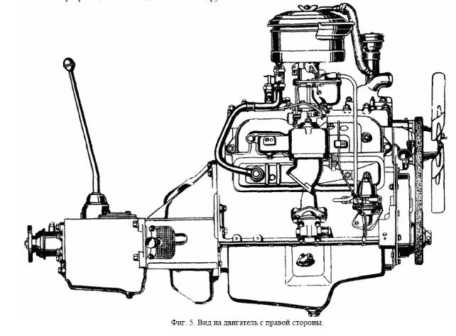
Engine GAZ-69 - four-cylinder, carburettors, differs significantly from nosoustoychivostyu and economical in operation. Most of its parts equally with the details of motion gateley M-20 and GAZ51, but it has a slightly higher maximum power and torque - ment in comparison with the engine M- 20. In Fig. 5 - 6 shows the general types of engine. Speed characteristics and fuel consumption curve shown in Fig. 7. In Fig. 8 - 10 show the longitudinal and transverse sections of the engine.
Block and Cylinder
Cylinder block. Engine cylinders are arranged vertically in series and the cast from gray iron together with the upper part of the crankcase. The cylinder block is fully interchangeable with the engine block of M-20. To reduce wear of the cylinders in the upper part of their pressed sleeve of acid-proof Chu guna, length of 50 mm. The thickness of the wall sleeve is equal to 2 mm.
These sleeves increase durability of the cylinders in 2 - 3 times. The block has a water jacket on the entire length of the engine cylinders. Inlet and outlet channels written in block separately for each cylinder in order to improve the filling of cylinders of combustible mixture. Saddles exhaust valves are made of special heat-resistant cast iron of high hardness and pressed in the block, saddle inlet valves are made directly into the body of the block. At the bottom of the block are four main bearings of the crankshaft, covers Coto ryh accurately recorded grooves made in the top of the crankcase. Each cover is fastened to the block two bolts, the heads of which pin: in the first three bearings - wire, the fourth -- Special shut-off plate. Caps bearings at the factory are final on developing joint with the block and therefore vzaimonezamenyaemy. The back plane of the block by six bolts fastened crankcase clutch, fixed on the block two mounting pins. The necessary alignment of the crankshaft and drive shaft gear provides final processing crankcase clutch assembly with a cylinder block. Therefore, re - furnish clutch crankcase from one block to another cannot.
Fig. 5. View of the engine on the right side.
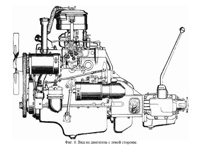
Fig. 6. View of the engine on the left side.
Cylinder head. The total for all cylin - firewood, removable cast aluminium alloy. Interchangeable with the head of the engine M-20. Intergovernmental do block and cylinder heads
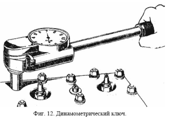
put sealing eliminating the gasket made of asbestos cloth, impregnated with graphite. The thickness of the gasket in a compressed state with - submits approximately 1,5 mm. Windows-burning chambers Nia and water holes in the lining edged sheet thickness of 0,25 mm. In order to avoid harassment of asbestos to the block and head, gasket, before directing the place to rub on both sides of graphite powder. Cylinder head is attached to the Block 23 studs, nuts are placed under the flat tsianirovannye washers. The order of tightening, as well as braces these nuts very important; tightening should be done in two receiving, at first tentatively and then final - Indeed, in the sequence shown in FIG. 11. We recommend using dinamometriche - Skim the key (Fig. 12) with controlled moments Volume tightening within 6,7 - 7,2 kg. Without a key tightening screws is usually carried Spanner wrenches from the driver's set of instrumenta, without jerks, the effort of one hand in the cottage - zhanie disruption studs or deformation of cylinders. Tightening or tightening the screws to make sure a cold start, as vsledstence of different linear expansion coefficients of aluminium heads and steel studs delay, produced on the hot engine, after it proved insufficient cooling.
Fig. 7. High-speed characteristics of the engine.
Fig. 8. Longitudinal section of the engine.
Crank Mechanism
Pistons - interchangeable with the engine piston M-20, GAZ-51, GAZ-63 and ZIM. Cast from heat-treated aluminium alloy, have flat bottoms and elliptic shape of the skirt. Magnitude of the ellipticity skirts 0,29 mm. The major axis of the ellipse is located in the plane perpendicularlar axis of the piston pin in the direction in which the piston side force acting on the connecting rod. For make skirt springy properties, it made U-shaped slot. When heated, while the engine, the piston due to an elliptic shape and U-shaped slits in the skirt expands differently: in the direction of the piston pin higher than in the direction SRI perpendicular to the axis. As a result, hot ellipticity of the piston decreases and its shape approximation etsya to round. This form allows you to reduce the gap between the cylinder and the piston in the direction is the real Via the lateral force that supports the work of the cold engine without knocking pistons and excludes edu - cation scoring pistons when the engine is at full capacity. At the head of the piston ring grooves, there are five. Upper, narrow groove serves to reduce heating of the upper compression ring by reducing heat transfer to him from the bottom of the piston. In second and third grooves are placed compression ring in the fourth and fifth -
maslosemnye ring ca. In the grooves for oil rings drilled holes through which oil is withdrawn from the walls cylinders is given in the crankcase. In the middle part of the piston there are two bosses with holes for the installation of piston pin. Under boss made two tide for fitting the pistons by weight. Piston standard size weighs 450 + 2 years To improve the running for the cylinders pistons coated with a thin layer of tin (0,005 mm). The pistons are installed in the cylinders so that the U-shaped slit skirt was turned aside opposite valve box. This side of the cylinder is not exposed to lateral forces in During the working piston. For repair purposes larger-diameter pistons are available: 82, 82,08, 82.24, 82.36, 82.5; 82.58, 82.62, 83; 83.25 and 83.5 mm. The numbers indicate the size of repair on the bottom of the piston.
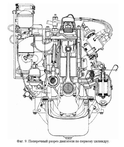
Fig. 9. Cross section of the engine on the first cylinder.

Fig. 10. Cross section of the engine oil pump.
Fig. 11. The sequence of tightening the screws fastening the cylinder heads.
Piston rings: two compression and two maslosemnyh. Accordingly unified with rings engine M-20, GAZ-51, GAZ-63 and ZIM. The rings are made of gray iron castings by an individual in a non-
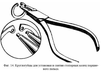
circular shape; this provides an appropriate framework material and sealing rings. Compression rings are the same size. The outer cylindrical surface of the upper - second compression ring, operating in very difficult conditions, covered with a porous chromium, which is 3 - 4 times increases its longevity. Increased durability of the upper compression ring in ity will be the durability of all other rings cylinder engine. To improve and accelerate the break - compression rings on the inner tsilind - psychiatric surface is a facet of, causes quick muscular especially those for small bias rings in the groove piston, in which they adjoin - Xia with the cylinder is not the entire surface, but only bottom edge. The rings are installed on chamfers piston upwards, towards the bottom (Fig. 13). Both maslosemnyh rings are the same. They have a slot for removing oil, snimaemo - On the walls of the inner cylinder in smallness of the piston. For a better running-in cylinder AMD outer surface of the second compression - tional and two oil rings exposed - Xia solderability. All rings have a straight lock with gap equal to 0,2 - 0,4 mm after installation but - Vågå ring in the cylinder of the engine. Piston fingers floating type, hollow. Harmonized with the fingers engines M-20, GAZ-51, GAZ-63 and ZIM. They are made of steel with hardening the outer surface to a depth of 1 - 1,5 mm with high frequency currents. From axial displacement fingers are held round spring rings set in annular grooves of both bobyshek piston. In engines produced until 1955 laying down lis flat retaining rings. The grooves in the piston for round and planar rings have a different configuration, and therefore such Pistons vzaimonezamenyaemy. Installation and removal of flat rings should be made by special kruglogubtsami (Fig. 14). When the engine piston pins perceived - The World Health Report large dynamic loads, therefore, for prevention in Nia tapping fingers gaps between them and the holes in the pistons and rods made minimal. For repair purposes fingers produced larger diameter at 0,08, 0,12 and 0,2 mm marked accordingly black, blue and brown paint.
Cranks - steel, forged, I-section. In upper end of connecting rod are pressed thin-walled sleeve of tin bronze. Bush has an opening coinciding with the pro - rezyu at the top end of connecting rod, to lubricate the piston pin. Lower end of connecting rod - Plug-in.
Fig. 12. Torque Wrench.
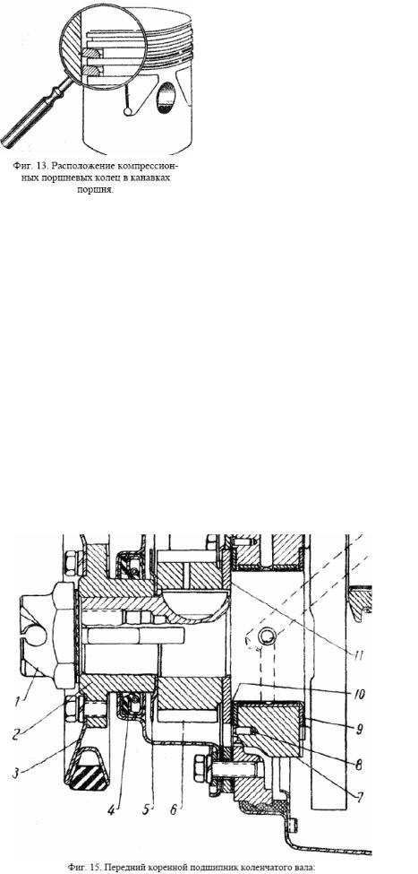
Fig. 13. Location compression - GOVERNMENTAL piston rings in grooves piston.
Lid of the lower head-credit pitsya to crank two bolts, grad - ki which the individual pin - tial. Hole in the bottom head connecting rod is treated as an assembly with its cover, so permute cover with a connecting rod on the other impossible. In place of transition of the lower second - nimble in the rod connecting rod has hole diameter 1.5 mm, through which is carried out grease degree of NOC cylinders, cams dis - duration of the shaft and plates tolkate - lei. This hole should be ob rascheno installing rods in side of the valve box. At the upper end of the connecting rod and on the cover of the bottom heads are boss, cutting off that the factory is carried out on the fit - schego weight of the connecting rod and the weight distribution between their heads. The difference in weight rods for one engine over 8 g is not allowed. Crank the engine GAZ-69 with the same engine connecting rods M-20 and VMS, but with vzaimonezamenyaemy connecting rods engine GAZ-51, which are asymmetrical lower heads.
Crankshaft - steel, forged, Four-, unified with the shaft of the engine M-20. Has a counterweight to the discharge of main bearings from the forces of inertia, statically and dynamically Balanced lansirovan. To improve the wear resistance of connecting rod and the root neck shaft hardened to a depth of 3 -- 5 mm. The diameter of the root necks - 64 mm, connecting rod - 51,5 mm. Neck connecting rod shaft for supplying lubricant to connecting rod bearings, combined with indigenous tails drilling channels having special WIDE deadlocks - Mud closed by threaded plugs.
Fig. 15. Front Crankshaft bearings:
1 - ratchet, 2 - hub, 3 - pulley, 4 - gland, 5 - slinger, 6 - the crankshaft timing gear, 7 - cover front bearings, 8 - pin, 9 - Rear washer thrust bearing, 10-front washer thrust bearing, 11 - thrust washer. Axial displacement of the shaft bearings are perceived front two persistent washers (Fig. 15) of steel, stained babbits tape. Value of the axial clearance is 0,075 - 0,175 mm Front washer 10 facing the surface, flooded babbit, to a steel thrust washer 11, sat -
Fig. 14. Kruglogubtsy for installation and removal of locking piston rings Vågå finger.
ing on the shaft at the pins and pressed to the side of main bearings. Rear washer 9 is facing surfaces Stu, flooded babbit, to the shaft collar cheeks. From the rotation washers held: front - two pin - mi, molded into the block and the lid and outside the seizure washers, rear - projection within the groove at the end of the cover bearings. At the front end of the shaft pins were planted on the timing gear 6, maslosbrasyvayuschee ring 5 and the hub 2, pressed to the side thrust washer 11 with a ratchet, 1 screwed in the butt shaft. By the stepped - tse six bolts privertyvayut stamped pulley drive the water pump and generator. In lid distribution gears placed samopodtyagivayuschiysya gland 4 front end of the shaft with a rubber cuff, which operates on the outer surface of the hub. While raising cap must be ottsentri - Immunized by glands in order to avoid leaks in this compound. Omentum rear end of the crankshaft comprises two semi rings made of prografichen - tion of asbestos cord invested in two clips. The upper clip is bolted to the side of the block, back - to the top of the bearing. Rear radical neck of the crankshaft has to seal maslosbrasyvayuschy shoulder, part of a ring-carved ku bearing. From this recess oil flows through a special hole in the crankcase. At the end of the crankshaft has a flange for mounting the flywheel.
Flywheel cast from gray iron and steel has Napressovannye toothed rim to put the moving telya starter. To find the top dead centre (ie VM) to install the ignition in the outer surface flywheel pressed steel ball. On both sides of the ball hit the 12 ticks, each division Coto ryh corresponds to one to degree of rotation of the crankshaft. Flywheel mass fixed to the flange of the four special bolts that have tight fit in the hole - stiyah. Nuts These bolts are tightened and the individual shplintovku dynamometer key a point in 7,6 - 8,3 kgm.
Inserts the corresponding connecting rod and main bearings of the crankshaft is interchangeable - mye, thin-walled, made of low carbon steel strip, flooded babbits special composition. The thickness of the steel strip connecting rod inserts of 1.45 mm, root - 1,9 mm thick layer of babbit respectively 0,35 and 0,4 mm. Width of the liner connecting rod - 28 mm. A small layer of babbit practically at work does not shrinkage, so the main and connecting rod bushings do not require the use of braces and adjusting pro - batches. Production of the necks of the crankshaft, liners and beds for them in the block and connecting rods with high accuracy allows replacement of inserts in the repair of the engine without fitting. Each bearing set for two of the liner, they are held in them by fic - compensating ledges within the grooves, which are available in rods and in the block. Both connecting rod and the liner are the same unified engine to the liner M-20 and ZIM. Non - large hole, which coincides with the hole in the bottom end of connecting rod for supplying lubricant to the cylinder cam camshaft and tappets to the plate, there is also in the liner, which is mouth - tive to the connecting rod cap to ensure their interchangeability.
Both liner bearings have a circular groove, which coincides with a hole in neck of the crankshaft. Inserts that are installed in the block are in the centre of the groove hole for supplying lubrication; deposits - Shi, set in the lid, such openings do not. In the rear bearing inserts to make additional annular groove located near their end. Of this, oil flows through the grooves in the insert and the hole in the lid into the crankcase Engine la. Inserts bearings vary in width: the width of the front bearing inserts - 30,5 mm, medium - 26 mm and rear - 42,5 mm. Inserts respective bearings Unification from certified forests to the liner engine M-20 and ZIM. The gap between the crankshaft journals and connecting rod liners and bearings lies in the Within 0,026 - 0,077 mm on the new engine. Bolts and nuts are indigenous types of bearings should be delayed dynamometer with key point in the 12,5 - 13,6 kgm for indigenous and 6,8 - 7,5 kgm for connecting rod bearings.
DISTRIBUTION MECHANISM
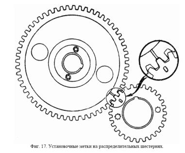
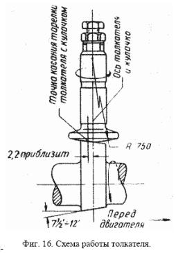
Camshaft steel, forged. Has four necks, who work in stalebabbitovyh sleeves pressed into the block. For ease of assembly of the neck are made of different diameter: the first - 52 mm, the second - 51 mm, the third - and fourth 50 mm - 48 mm. Profile of the intake and exhaust cams is the same. Kulaks, ki grinding width of the cone size of a 7,5 '- 12.5' for co - communication speed pusher at work (Fig. 16). For one with a camshaft carried out: ex - Dunhill Homme drive a petrol pump and gear drive oil - second pump. Cams, cam and pinion to increase the wear - the stability of the surface subjected to tempering. Camshaft driven by two six - thorns with spiral tooth of the crankshaft of the engine. Gear on the crankshaft - steel, at a switching shaft - textolite with steel or cast iron hub. Both six - Terni have threaded holes for the puller. To ensure correct phase distribution installation meshing gears should be made on labels (Fig. 17). From axial displacement camshaft holding hard steel flange 6 (Fig. 18), privernuty two bolts to the block. Between the ends of the neck of the shaft and hub gears are trapped spacing washer 5, whose thickness of 0,1 - 0,2 mm larger than the thickness of ness persistent flange, resulting in a necessary - dimy axial clearance of the shaft.
Round blade plate, steel. Worktop thickness Katele melting chilled cast iron to ensure high durability and polished to area. At the top of the pusher made threaded hole into which the adjusting bolt 7 screwed (Fig. 19), latching lock nut 8. With this bolt is governed by the gap between the pusher and valve.
Fig. 17. The installation marks on the timing gear.
The rounded surface of the head of the adjustment bolt subjected to surface hardening and otshli - fovana on the field. To even out the wear plates and rods pushers should when the engine is commit - PRE-rotate. This is achieved by grinding plates on a sphere with a radius of 750 mm and a small Inclination Mr. cams camshaft, resulting in a point of contact plates with a few fist-mixture schena the axis of rotation of the pusher.
Valves. The inlet valve is made of chrome steel 40Kh, graduation - of heat-resistant steel SH8. The outer diameter of the intake valve is 39 mm, exhaust - 36 mm. Both valves have a corner saddle LA 45 ° and lift height of 9.2 mm. The top of the head valve has a slot for lapping at the lower her side of
the head abbreviations: Tech - Graduation and VP - inlet. At the bottom of the valve stem 2 (Fig. 19) made recess, which includes his shoulder Two crackers 5 bumper spring. Both valves operate in the guide bushing. Bushings are made of cast iron and final PRE-processed after pressing the block.
Fig. 16. Scheme of work pusher.
4 valve springs are made of special Noah, oil-hardened spring wire mark C-65A diameter of 4.1 mm. To increase the fatigue strength of the springs are blasting. The springs have a variable pitch winding for the decrease in Nia vibration. When installing the end of the spring with a smaller step of winding should be turned up. The lower end of the spring rests on the plate 6, a conical socket, which is under the action of the spring sits tightly on the conical surface tions crackers. All details of the distribution mechanism of the engine GAZ-69 is fully harmonized with similar governmental parts engine M-20, GAZ-51, GAZ-63 and ZIM.
Engine lubrication system
Engine lubrication system combined: the pressure and spray (Fig. 20). Under pressure tion lubricated bearings, crankshaft and camshaft and rods pushers. Pumped - my pump oil flows through pre-filter in the longitudinal channel of the engine oil and Ott - Yes through the cross-channel unit to the main bearings and camshaft bearings, and also for special longitudinal channel to the rod pushers. All channels for oil in the block - Drill - WIDE. By crank neck oil served on drilling channels available in the body of the crankshaft from its bearings. The surface of the cylinder, piston pins, cams camshaft, tappets and plates valve stems are lubricated by oil spray, which derives from the gapbearing knee chatogo and camshafts. The walls of the cylinders are lubricated by oil jets also emitted from the holes in the lower second - adroit rods. Distribution gears lubricated with a pulsating stream of oil coming from the front
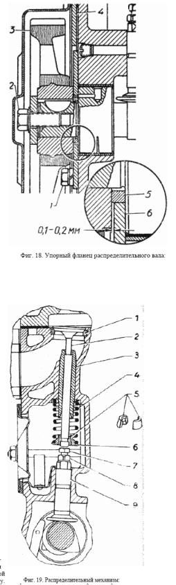
Fig. 18. Hard flange of the camshaft:
1 - stubborn attachment bolt washers, 2 -, six-bolt mounting However, 3 - timing gear, 4 - plate engine, 5 -- spacing ring, 6 - thrust flange.
Fig. 19. Distribution mechanism:
1 - saddle valve, 2 - valve, 3 - in - pravlyayuschaya bush, 4 - spring, 5 - rusk, 6 -- plate, 7 - the adjusting bolt, 8 - nut, 9 - Pusher.
Bearing camshaft through the tube 1. Front neck camshaft has two grooves in which tube 1 twice for every revolution of the shaft is connected to a channel in the block. From front bearing is lubricated and hard flange 6 camshaft two drilling holes in the neck, located at an angle of 90 ° (Fig. 18).
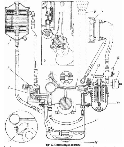
Fig. 20. Engine lubrication system:
1 - tube lubricant distribution gear, 2 - oil pump, 3 - pressure-reducing valve, 4 - fine filter, 5 - scheme lubrication cams camshaft and cylinder wall, 6 - oil filler, 7 - oil cooler, 8 - tap oil - tion radiator, 9 - gauge oil pressure gauge, 10 - pre-filter, 11 - floating maslopriemnik, 12 - drain plug holes, 13 - relief valve-filter.
Engine lubrication system includes an oil sump, maslopriemnik, oil pump, filters for coarse and fine cleaning of oil and oil cooler. Capacity oil system, including filters and oil cooler, is 5.5 liters. Oil Capacity through the filler pipe 6 (Fig. 20), hermetically closed, passer lid. The level of oil in the crankcase is checked by rod-probe, which is placed in the tube ARGET side of the engine (Fig. 21). At the bar marked label "P" - the upper limit and "O" - the lower limit. When the engine is necessary to maintain the oil level within the upper half of the distance between the marks "P" and "O". The decline in oil below the label "O" is dangerous because it may cause podplavlenie bearings and in This in no way is unacceptable. Excess levels over labels "P" is splashing oil and candles rapid coking of piston rings. Oil pressure in the system when the vehicle speed 45 km / h shall be within 2 - 4 kg / cm 2 . On cold, cold engine, it can rise up to 4,5 kg / cm 2 But in hot summer weather to fall to 1,5 kg /cm 2 . Oil Pressure at medium engine speeds Me - than 1 kg / cm 2 indicates a malfunction in the sys - IU, and further operation of the vehicle must terminated prior to its elimination. At low idle - Dry run oil pressure should be approximately equal to nym 1 kg / cm 2 or slightly below, depending on the degree worn motor bearings. To control the oil pressure in the engine is electrical pulse pressure gauge, a sensor which vvertyvaetsya in a special socket on the filter housing rough treatment. It should be borne in mind that in these Numbers above the oil pressure in the system are ignored error sensor and receiver, oil pressure gauge, serviceability which should be periodically pro - Believing control manometer or the manner specified below (see the chapter
"Electrical"). In the lubricating system of engine has two valves: pressure reducing 3 (Fig. 20), located in the lid oil pump and a bypass 13 in the case prefilter. The valves are adjusted at the factory, and change this rule in operation (through the stocking of washers under the spring, changing the thickness pads under the cork, reducing the number of coils, etc.) is prohibited. Pressure reducing valve 3 limits the oil pressure limit value of 4,5 kg / cm 2 and thereby protects it from excessive build up of pressure when the engine is at large equip - max, as well as starting it with frozen butter. Bypass valve 13 automatically turns off the oil filter (through which passes all the engine oil) in the case of clogging of the filter element and it skips to the trunk unfiltered oil. Bypass valve is in the pressure drop in the filter 0,7-0,9 kg / cm 2 .
Oil sump made of steel, stamped. The capacity of the crankcase up to the mark "P" on schupe is 4 liters. Inside the casing has a wall which protects the oil from splashing when driving. On the left side to side wall of the crankcase privernut four bolts, pipe, which includes the stop of the rod-tube
probe is secured to bolt. On the other hand crankcase three rivets attached to the discharge pipe oil cooler. All flanges, as well as front and rear radiused part, Carter compacted cork pro - masonry with twenty bolts, which he privertyvayut to the bottom plane of the block. The bottom part of the crankcase has a hole to drain the oil. In hole screw cap with sealing washer. Maslopriemnik floating type, hinged to the tube waiting for the oil pipe - pump. The presence of floating maslopriemnika provides admission to pump more pure oil, in - walking in the crankcase. Maslopriemnik equipped with fine wire mesh and is therefore a primary filter engine, which prevents oil pump from contamination. Grid (Fig. 22) is in the middle of the ring, lined hole. This hole is automati - cally valve, acting on the dilution created by the pump, in case of contamination of the grid.
Fig. 21. Oil level.
Fig. 22. Scheme of work maslopriemnika.
and - when nezasorennoy grid, b - when clogged grid. When the net is not clogged, it is pressed against this opening to the pallet maslopriemnika and oil in walks into the pump through the holes in the grid. When contamination grid increases its resistance to the passage of mas - LA, and under the influence of dilution created by the pump, it is pushed to the side of the tube, releasing the hole - stie, through which enters oil.
Oil pump gear (Fig. 23), installed outside the engine, on its right side. Uniform with the pump motor M-20. Pump casing its cylindrical shank part of the on - Verst tide block and secured it with two bolts. Between the flange of the pump housing and the tide Block put gasket from paronita thickness of 0,5 mm. The roller pump is in rotation schenie from the camshaft gear, which engages the helical gear 2, sitting at the upper end of the roller and the fixed pin. At the lower end of the roller Pressing the leading six - nya pump 8, fixed pin, perceiving axial force arising in helical gears his drive and downward toward the lid of the pump. Between the face gear 2 and the cross rail liner also allowed
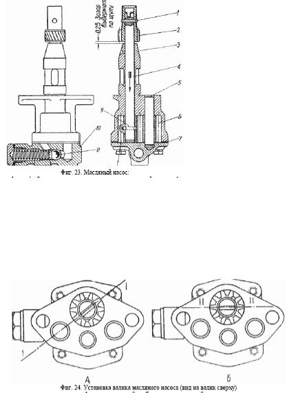
clearance 0,2 - 0,4 mm. At the upper end of the roller 4 is asymmetrical its axis groove to drive the distributor lighting - Niya. Driven gear 6 is free to rotate on an axis 5, pressed into the pump housing. Both cylindrical gear oil pump are identical and have a straight tooth. Driven gear phosphating. Bottom pump casing lid 10, which placed pressure-reducing valve, attach - My four bolts. Between the body and lid set paronit gasket thickness 0,3 - 0,4 mm. End the gap between the gear pump and the lid is in the range. 0,125 - 0,475 mm. Increasing this gap as a result of laying greater thickness dramatically reduces pressure tion, developed by the pump. To reduce noise at work reducing valve between the ball 11 and springs 13 installed point - Officer cap 12. Diametral clearance between ball 11 and the channel in the lid is 0,079 - 0,189 mm, so this valve is very sensitive to contamination of crankcase oil and by ingestion. channel of foreign particles the ball wedged in it, causing a drop pressure in the lubricating system of engine. The pump starts to work only with in - lichii oil in it, so when setting it necessarily be filled with oil in two holes in its flange. The engine pump, situated obliquely, so that oc - tanovkah engine oil does not flow out of it can. To ensure proper position - Nia Distributor ignition setting mas - lyanogo pump on the engine must be productivity be conducted by the following:
1)to the crankshaft of the engine the position corresponding to the top of Meurthe - howl at (VM etc.) the compression stroke, the first Chi - lindre (see "System-lighting Nia ");
2)turn the oil pump shaft so that the notch at its end, in which includes the spike shank Distributors telya was located at an angle so as shown in Fig. 24 A;
3)in this position, without turning his body, gently insert the pump in the unit, observing that, helical gear it would not to touch the walls of the holes on the block and do not turn around. When
the propeller -
Fig. 23. Oil Pump:
1 - pin 2 - gear drive pump and the distributor, 3 - body, 4 - Shaft, 5 - axis, 6 - led by the gear, 7 - gasket, 8 - Leading the sixth turn, 9 - pin 10 - cover, 11 - ball pressure reducing valve, 12 -- guide cap spring 13 - spring 14 - gasket cork, 15 - cork.
Vai gear pump will enter into engagement with helical gear and the camshaft rotates, the slot roller takes the horizontal position shown in FIG. 24 MB When installing the oil pump should put a new gasket between his body and block the Qi -
lindrov.
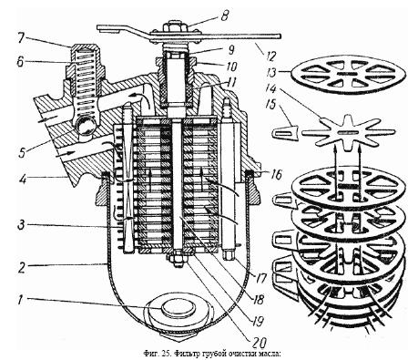
Fig. 24. Install the oil pump shaft (a view of the roller on top) A - before setting the block, B - after setting the block. Pre-Filter oil (Fig. 25) plate, slit, is unified with the filter by moving - telya M-20. Through this filter will pass all the oil to pump to lubricate the engine, and therefore negligible internal resistance (pressure drop before and after the filter is equal to approximately 0,1 kg / cm 2 ).
Fig. 25. Pre-Filter Oil:
1 - plug the drain holes, 2 - filter housing, 3 - rod scrape plates, 4 - filter housing, 5 - ball bypass cluster Pan, 6 - spring relief valve, 7 - congestion relief valve, 8 - nut grip roller, 9 - spring roll, 10 - Nut Gland, 11 - gasket, 12 - handle roller, 13 - filter plate. 14 - intermediate plate (asterisk), 15 - is removed plate, 16 - gasket, 17 - front desk, 18 - roller filter, 19 - Lock washer, 20 - Lock nut. PreFilter large particles retards the impurities and dirt (over 0,1 mm), as well as resinous education available in the oil. The filter element consists of a set of his Me - full metallic, molded filter plates 13 of thickness 0.35 mm and thin intermediate star - 14 check the thickness 0,09 - 0,10 mm, collected alternately on the central shaft 18. The plates are compressed at Vale Nike between the upper and lower bearing washer through the nuts 20, screwed on the lower end of the vali - ca and fixed lock washer 19. Clearances between the filter and intermediate plate form element filtering slit width of 3 mm. Passing under pressure through these cracks, oil-eyes nated from mud and tar formations. To clear the filter from the crevices of mud between its plate - 13 mi put scrape plate 15 of thickness 0,07 - 0,08 mm, typed on a separate square rod, 3-set in the casing. When turning the shaft 18 together with turning also the filter element, while still scrape the plate 15 removes dirt from filtering - ning slits element. During one rotation roller filter element is cleaned the whole circumference. The rotation of the roller shall handle 12, coupler which is connected with a roller through pru - zhiny 9. Resultant between the inner surface of the coils and the outer surface of the roller and clutch friction when turning the handle in a counterclockwise twisting the spring, in resulting in the handle and shaft rotate as a whole. In the reverse rotation of the spring is unwound, and thereby made free lift ruko - yatki. Handle standstill on the roller nut 8 with left-handed, zakernennoy top three spots. For auto matic cleaning the filter handle 12 is a thrust with a pedal starter, when clicked, roller the filter is rotated by 15 - 20 °. The force of the pedal starter transferred to the handle through the spring, that ensure its inclusion in the clogged filter or thickened, cold oil. If the engine constantly give birth to the starting handle, then roll the filter be rotated by the handle of the hand of every Day 1 - 2 turns. Care for the filter is to remove the sludge at each change of engine oil through the drain hole plugged with 1 (Fig. 25) and flushing the filter every 6 thousand kilometers of the car. Drain oil from the tank to the hot engine, after turning the roller filter 1 - 2 turns. For washing and cleaning the filter it should be removed from the engine, clean the tank and filter element from dirt and small particles,
thoroughly wash the item in benzene, rotating roller on the handle, and then rinse in the liquid oil. After installing the filter on the engine and the accession of his drive, make sure to rotation schenii roller when pressing the pedal to the refusal starter.
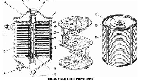
Fine filter oil (Fig. 26) has a replaceable filter element DASFO-2, Zaderei - residing tiny particles of dirt, sand, metal, carbon, etc., are in a suspended state, SRI in the oil. Uniform with the filter engine M-20.
Fig. 26. Fine filter oil:
1 - plug the drain holes, 2 - filter element, 3 - tube inlet hose, 4 - housing cover, 5 - stud,
6 - Spring, 7 - gasket lid, 8 - Corps, 9 - disc filter element, 10 - installation of the filter element, 11 - central rod, 12 - screed, 13 - overflow hole of the filter element, 14 - tube exhaust hose
15 - handle of the filter element, 16 - cover of the filter element, 17 - screed.
Since the filter element has a great resistance to passing through it smoothly, then This filter is included along an oil pipeline engine. Oil enters the filter housing, for - Rack mounting on the dashboard of car, through the hose 3 from the oil pump cover and freely poured through the hose 14 in the crankcase. Top of housing rose lid 4, which tightened bolt 5, vvertyvaemym in the central hollow shaft 11 Corps. At the core is placed a removable filtering - ning element 2, consisting of a set of cardboard discs 9 thickness 0,5 - 0,7 mm and shaped pads 10 thickness of 3 - 3,5 mm. The number of seals in the elements 28 - 32 pieces. Top and bottom of the filter set closed with metal lids 16, fitted with a cardboard glands, and is tied with four metal ties 17 with a force of 25 kg. Upper lid has a wire handle 15 for you - Beware when replacing the element. Oil from the shell falls into the cavity formed by the discs 9 and shaped spacers 10, where deposited his contaminating particles and resin formation. Hence oil pressure seeping - etsya between the discs and pads jumpered radial grooves 10 in the past and it goes to central square opening element. From the inner cavity of the cleaned oil passes through the ca -
librovannoe hole 1,6 +0.1 mm, located in the top of the hollow rod 11, and enters the crankcase. For a quick warm-up filter and accelerate the circulation of oil through the element in the lower lid 16 there is a small hole 1,1 +0.05 mm, to which oil bypassing the filter element, in walks out of the case after six holes located in the holder of the lower flange of the cover. In results those that, when starting a cold engine oil circulates through the overflow hole, heats filter, and he begins to work normally. In the case of clogging or overflow hole of connecting holes in the bottom filter cover - Officer element virtually ceases to operate. Effects of fine filter is very effective, and up until his filter element working oil in the crankcase is bright. Care for the filter is to remove the sludge after one thousand kilometers and with ca - zhdoy change the engine oil through the drain hole in the hull, closed cap 1 (Fig. 26), having tapered thread, and the periodic replacement of filter elements.
Remove sediment from the filter should be the same as a pre-filter, on a hot engine,
when the oil and sludge liquid. The filter element should be changed in the black for oil in the crankcase, when taken out schupe hundred - novyatsya invisible its label. The service life of the filter element depends on the quality of oil and the degree of deterioration Engine To; for new engines, he is several times greater than for engines with a strong pass gases through the piston rings. The average service life of filter elements is 2 - 3 thousand kilometers of the car. The change of the filter element is
recommended to coincide to a change of oil in the crankcase. To change the filter element is necessary:
1)remove the lid 4 Filter assembly with bolt and spring;
2)Loosen the stopper 1 drain hole and drain off oil from the shell, remove the filter element and completely wipe the inner surface of the filter housing with a rag;
3)insert a new filter element, wrap the cork and pour the drain holes in the body fresh butter;
4)to check whether your pads 7, without removing it from the cover, and if necessary, replace new;
5)Install the cover in place on the label, available on the body and lid, to avoid the appearance
leaks, and turn stud 5. Should not make too strong tightening the bolt, since the ne - retyazhke it can damage the gasket;
6)let the engine, check for leaks in the joints of oil filter;
7)to stop the engine, check oil level in the crankcase and, if necessary, add it to the mark "P" on masloizmeritelnom rod.
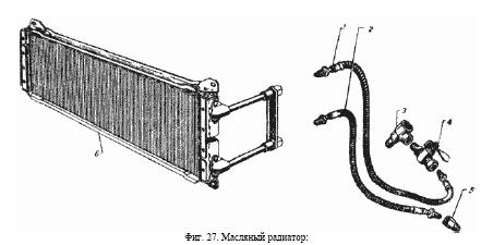
Oil heater - tubular-plate, single-row (Fig. 27). Skeleton oil cooler consists of eight flat brass tubes
with soldered to them with steel, solder cooling plates and brass tank lid. Skeleton are soldered to the right and left tanks, enclosed in cover, and they are soldered steel frame, which is attached by four bolts to the leading-gon On the radiator. Right-wing, steel tanks are excretory tubes, which, through flexible hoses with - unifying the radiator with the engine. Oil cooler, as well as oil fine filter, includ - chaetsya parallel oil pipeline engine. Oil in the radiator comes from the filter housing rough cleaning and passing through it, cooled, poured into the crankcase. Switching the oil - tion is the radiator valve 4 located next to the shell-filter. Oil heater is used to prevent overheating of oil in the long-term operation of the engine with heavy load, as well as in conditions of high ambient temperature. It should include while riding in the summer, and, regardless of the season, when driving on bad roads with a large on - Transshipment engine and low speed traffic.
Fig. 27. Oil radiator:
1 - inlet hose, 2 - exhaust hose, 3 - inlet hose fitting, 4 - tap, 5 - choke exhaust hose, 6 - frame radiato - ra.
Caring for oil radiator is to verify the density of compounds and oil-lines, as well as in periodically, at least as a 1200 km path, washing it and cleaning hoses. Flushing the radiator must be done if you disconnect the hose from the engine with liquid oil passing it under pressure in the opposite direction of normal circulation. Care for the engine lubrication system consists of a daily inspection of oil in the crankcase and if necessary, its top up to the mark "P" on masloizmeritelnom rod. Periodic change of mass LA should be performed, guided map grease car depending on the quality of the applied oil, its degree of contamination and the state of the engine. Terms of oil changes can be significantly Uwe - licheny, if timely and regularly replace the filter element oil filter wastewater thin - ki. Drain oil from the crankcase and from the two filters to the car after work when it hot and drain well. After the oil spilled, it should turn a few times crankshaft Engine starting handle, not wrapping up drain plugs holes. For the engine lubricating oil must be used, specified in the map grease car (p. 183). Using air or diesel oil can only be subject to liquefaction of spindle - nym or turbine oil to the viscosity: the summer of 5,5 - 7, and the winter 3,5 - 4,5 Engler at 50 ° C. Application Lubricating neiznoshennogo engine oils with high viscosity is unacceptable because it leads to Uwe - An increase in fuel
consumption, increased wear and difficult starting the engine. To determine the viscosity of oils or mixtures thereof should use special garage whiskey zimetrami. For heavily soiled crankcase to the engine wash liquid (spindle) mas - scrap used for flushing the engine kerosene in any case not allowed. Letting the dirty oil in Carter pour 5 liters of wash oil, and turning the candle, quickly rotate the crankshaft starting py - koyatkoy within 2 - 3 min. After this flushing oil is poured, and poured into the crankcase with fresh oil.
DEFECTS IN THE GREASE AND THEIR ELIMINATION
1.The fall of oil pressure at low and medium speed to zero at neiznoshennom engine. Prica - Noah is the blockage of the reducing valve oil pump located in its lid. For troubleshooting, you need to carefully remove the lid of the pump, knowing that with her and falls led gear, disassemble, rinse the cavity pressure-reducing valve and its parts and re-assemble. If be found during the inspection of heavy wear or breakage of teeth of the guide spring cap, then it can not put back, but the noise of the valve of this increase. Install guide cap to recess to the ball. Before the assembly is necessary to fill cavity lid with a thick oil, the same oil to moisten waged gear and quickly add cover to the body, without which the dry pump will not work and may occur podplavlenie. podshipni - kov.
2.Reduced oil pressure at all engine speeds. The reason for this may be:
a)the failure or refusal to work the oil pressure gauge. This is the most frequent cause. Elucidation of the causes of failure should always start with a test gauge. Checks should be pro - harass or control tested manometer (see below under "Electrical");
b)clogged the oil-filter when the oil passes through the bypass valve and line pressure is reduced by approximately 1 kg / cm 2 . Eliminated by washing and removing the filter;
c)substantial deterioration of crankshaft bearings, causing increased oil consumption in increased clearances. Eliminates replacement liners and connecting rod, if necessary, bearings or the use of oils with high viscosity;
g)long engine overheating or a strong spring wear reducing valve, resulting which spring sits and loses elasticity. It eliminates the formulation of a new spring;
d)seizure maslopriemnika in the up position or operation of the engine with low-level its oil, causing a leak of air into the suction cavity of the oil pump.
Seized maslopriemnika can be found through the drain hole in the crankcase is fused with oil;
e)failure of the oil pump due to wear or looseness in the joints.
3. Increased oil consumption engine. The reasons for this are:
a)wear of piston rings. Typically, piston rings should be changed after 35 - 40 thousand km pro - racing car;
b)failure of the crankcase ventilation (see section below, "the crankcase ventilation);
c)Engine malfunction glands, resulting in leakage of oil through there gaskets and other seals. Eliminates replacement of oil seals or tightening sealing compounds engine.
Crankcase ventilation
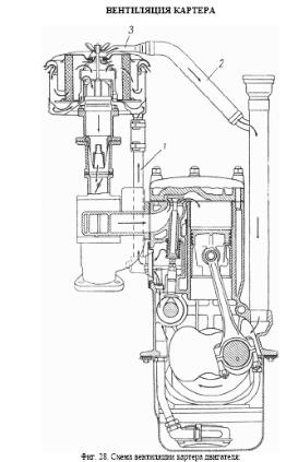
Fig. 28. Scheme crankcase ventilation:
1 - the branch exhaust ventilation, 2 - inlet branch of ventilation, 3 - nozzle air filter.
Crankcase ventilation system - forced, closed, avalvular (Fig. 28). Valid through thinning of the difference in different zones of air filter, resulting in a suction is carried out reflection oped gas in the suction pipe and the flow of fresh air in the crankcase. Exhaust Branch 1 consists of a ventilation tube outer diameter 19 mm, connecting the valve box with lid lower reservoir of the air filter. Ventilation Induced ventilation branch 2 consists of a hose inner diameter of 18 mm, which connects the central hole in the lid of the filter through a special, printed NACO - nechnik 3 with a curved tube oil-filling pipe. Tip 3 embodies the same bolt, Coto Eye mounted air filter to ensure that this branch has always been attached to the filter after disassembly. With the help of ventilation of the engine exhaust gases are removed, as well as a pair of gasoline-penetrating penitents through leakages piston rings into the crankcase. Thus, oil is protected from the "aging" and dilution of gasoline, and polished surface of the engine - from attack by acid, which edu - ized by the connections oxide gases and water vapor contained in exhaust gases. Not allow the engine to the oil-filling open orifice tube or looseness in compounds of the ventilation system. Because of the dilution created by the branch exhaust ventilation in Carter will be sucked in a lot of dust, greatly increases engine wear. Care for the crankcase ventilation is to verify the density of connections and purification of tarry by - proposal of tubes and hoses. It should be remembered that significant gaps in the gas piston ring tsami, or with a strong engine wear, crankcase ventilation is unable to cope with exhaust gases, resulting in the crankcase creates high blood pressure, causing oil to flow through the glands, and other looseness of the engine. This ultimately leads to increased operating costs of oil on the car. Increased pressure in the crankcase, with all the ensuing consequences, can occur also in the running, neiznoshennom engine due to deposits on the tubes and hoses, and consequently Consequently, the restriction of flow areas. Clear all tubes and hoses crankcase ventilation should be pro - hobnob not less than 6 thousand kilometers of the car. After 12 thousand kilometers should scour also the labyrinth in the back cover of an oil separator valve box, removing it from the engine.
COOLING SYSTEM
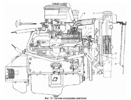
Engine cooling system - liquid, closed with forced circulation created centrifugal water pump (Fig. 29). Closed (sealed) system significantly reduces the loss coolant evaporation and therefore does not require frequent filling-up of the radiator. The system of cooling - ation included a boiler and engine start-up heater radiator body (see "Kuzo - you "). The capacity of the system with a boiler start-up
heater - 12 liters, without the boiler - 11 liters. Thermal regime of the engine has an extremely great influence on the efficiency of its work and life. Lack of engine operating temperature affects the evaporation of fuel, and it is, a capacitor - Cyr, flows down the walls of the cylinders, washing them with the oil film, which sharply increases the wear-qi lindrov, pistons and piston rings. The oil is diluted with petrol and loses its lubricating properties. Therefore, the temperature of cooling water in the system should always maintain the highest in the pre - ai 80 - 90 ° C. It is also crucial to reduce the heating time of the engine at its start. The optimum thermal regime of the engine is supported by a thermostat, blinds Radiation torus and thermal insulation cover that is worn on the hood of a car in the winter. To control the water temperature in the instrument cluster car has a thermometer, the sensor co
-torogo vvertyvaetsya in the cylinder head. On the dashboard, left, in addition, there are signal green light, which illuminates when the temperature of water in the cylinder head 92 -- 98 ° C. If ignition of the lamp to immediately stop the engine and eliminate the cause of his re - heating of. The direction of circulation of water in the cooling system is shown by arrows in FIG. 29. From the lower tank of the radiator water is water pump in the engine through the cylinder jacket water distribution pipe 2, passes along the block. This tube has four cut-out located against the exhaust valves, resulting in a more intensive cooling of hot places the engine. From the cylinder jacket through the holes in the block and the laying of water enters the jacket of the head and over - order through the thermostat and its nozzle (with a hot engine), the upper radiator tank.
The thermostat is placed in the outlet cylinder heads and has two valves: the basic, let the water in the radiator and the bypass, carrying water circulation system in addition to ra - diatora (Fig. 30). Uniform with a thermal engine M-20, GAZ-51, GAZ-63 and ZIM. When the water temperature to 68 ° C, the main valve 2 thermostat is closed, and bypass valve 5 is closed (Fig. 30 A). In this position the thermostat on the engine is running water from the cylinder head-translational em through two windows in the side surface of its housing 4 to bypass the channel back to the water pump, bypassing the radiator. Since the number of circulating fluid inside the water jacket of the engine did not conduct
-to, it quickly heats up. When the radiator heating body water also circulates and Th - Res heater. When the water temperature in the engine reaches 68 - 72 ° C, the main valve 2 begins to open - vatsya and implement a partial circulation of water through the radiator. When the water temperature at 80 - 86 ° C oc - thus a key valve is fully open and the bypass valve 5 closes the window on the thermostat housing and all water in the cooling system begins to circulate through the radiator.
Fig. 29. Cooling system engine:
1 - water pump, 2 - water distribution pipe, 3 - Circulator, 4 - exhaust pipe radiator, 5 - plug radiator 6 - Radiator, 7 - Fan, 8 - blinds.
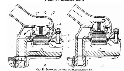
Fig. 30. Thermostat engine cooling system:
A - thermostat valve is closed, B - the thermostat valve is open, 1 - pipe exhaust valve cylinder heads, 2 - valve thermostat main Noah, 3 - laying thermostat, 4 - thermostat housing, 5 - thermostat bypass valve, 6 - laying pipe, 7 - cylinder thermostat.
Opening and closing valves 2 and 5, the thermostat automatically by changing the length corrugated container 7, which lies volatile liquids. When the tempera - tours of water pressure inside the cylinder increases and it becomes longer, and with it the rise and both valves; with decreasing temperature and decreasing cylinder valves fall down. Between the upper thorium body thermostat and rubber gasket pipe is installed 3 to prevent the passage of water into the radiator when the main valve closed. To prevent education Nia air sacs in the system in pouring water into the radiator, the plate valve 2 thermostat made no - large hole. The thermostat in the cooling system significantly reduces warm up time of the engine and automatically supports the required temperature of water in the cylinder jacket. Because, if the thermostat su - I can freeze the radiator (due to cessation of circulation of water through it), it is necessary to close blinds and radiator heat insulation.
Water pump centrifugal type (Fig. 31) is unified with the pump motor M-20, GAZ-51, GAZ-63 and ZIM. On the roller pump 4 from the outer end of the planted hub for mounting the drive pulley and fan. The pump is powered by a wedge-shaped belt pulley from the crankshaft of the engine; this same belt actuates an electric generator. The roller pump 4 is mounted on two ball bearings standard size 40X17X14 mm between which there is distance sleeve 11. Internal cage tightly sandwiched between the hub 8 and the locking ring 13 compress - Volume in the groove roller. External clamps are held in the axial direction from one side cross rail cor - Busan, on the other - spring, locking ring 10, within the annular groove on the end of the shank pump casing. At the ends of the roller has Lysko and internal threaded holes in the ends. Openings impeller 2 and the hub 8 stitched with the ledge under Lysko, thereby preventing their conductivity rachivanie on the shaft during operation. From the axial displacement rotor and hub are held flat washers and bolts, 1 set out from the weakening of spring washers. The space between the bearings nicknames filled refractory lubricant Approved (1 - 13) through the lubricator 5, vvertyvaemoy in the body. For Retention lubrication bearings are external to the special felt seals (tallow - ki). The grease in the bearings is supplied to the syringe until it begins to go out of control - 6 miles to the pump casing. For the convenience of monitoring the emergence of lubricant in a test hole pulley drive has two openings on its conical surface.
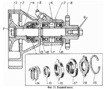
Fig. 31. Water pump:
1 - attachment bolt rotor and hub, 2 - rotor, 3 - pump casing, 4 - shaft, 5 - pressmaslenka, 6 - control hole Release lubrication in the body, 7 - bearings, 8 - fan hub, 9 - washer, 10 - locking ring in the body, 11 - distance sleeve, 12 - control the hole to exit the water leak in the omentum, 13 - circlip on the shaft, 14 - spring omentum, 15 - inner ferrule gland 16 - outer ferrule gland 17 - rubber sleeve, 18 - textolite washer, 19 - Keyhole ring gland.
Gasket pump is samopodtyagivayuschimsya gland, located in the impeller and consisting of a rubber sleeve 17 with two ferrule 15 and 16, textolite thrust washer 18 and pru - zhiny 14. Textolite washer 18 is retained in the impeller two ledges, falling in the corresponding a feasibility slotted rotor. In position washer 18 with ground surfaces is pressed against the polished end face body spring 14 and creates a seal, prevent - schee leaking water from the cavity of the pump, the rotation omentum, together with the impeller and roller. The flow in - dy on the roller and the reverse side textolite Washers prevents rubber collar 17. To improve the SMPs - batyvaemosti textolite puck to the body of the outer its surface is lubricated with a thin layer of graphite SmAZ - ki. Ingress of water into the bearings in the tallow-drip ka, prevents ring vodosbrasyvatelem (channel - Coy) on the arm. Therefore, in no case be closed hole 12 in the body, as this water is inevitably penetrate into the bearings and lead them out of action. Loss sealing gland, causing the leak of water from pump casing, is mainly due to wear textolite thrust washer 18. To replace worn parts gland pump should be removed from the engine and got caught in the grip of the hub 8 fan. Then unscrew the bolt 1 and the two washers, refusal to turn the nut puller 2 (Fig. 32) in the impeller pump and rotating bolt 1 puller, vypressovat impeller with seal.
Fan - shestilopastny, stamped. Fastened to the crosspiece flange hub 8 (Fig. 31) stamped pulley with four bolts. Care for water pump and fan is a periodic lubrication of bearings, according map grease the car and check the belt tension. Belt tension is checked by pressing it with your thumb, as shown in FIG. 33. Proper belt tension corresponds to the prog - Bu it with a 10 - 15 mm. Too little tension causes the belt slip at high equip - max engine and its separation from heat; too strong - disables bearing water pump and generator. Drive belt to protect from expose it to grease, as it destroys the belt and causes it to slip. After contact with belt oil should be immediately removed it with a clean, lightly-QS chennoy in gasoline with a rag. Grease bearings water pump should done until it appears from the control hole - stiya on the case. After that, the excess grease should must be removed to avoid grease on the fan belt.
Radiator - tubular - plate (Fig. 34). To flat tubes, located in three rows around perimeter of the cooling plate soldered red copper. Top and bottom of the tube soldered to the stamped brass tanks, which are attached to the inlet 6 and exhaust pipes 15 radiator. Behind, to the side racks mounted radiator fan shroud 16, the ad - mong the four special brackets - oil radiator. In the lower part of the exhaust pipe 15 vvertyvaetsya drain tap 14. In the filler neck of the upper radiator tank welded tube parootvodnaya 10. The radiator is fixed in four points. Below - on two rubber pads 2 and 3, strapped with bolts 4, the sides - to the mud flaps of the wings by rods 13. Cork radiator (Fig. 35), hermetically
 Loading...