

Page 1

USER’S GUIDE
Page 2
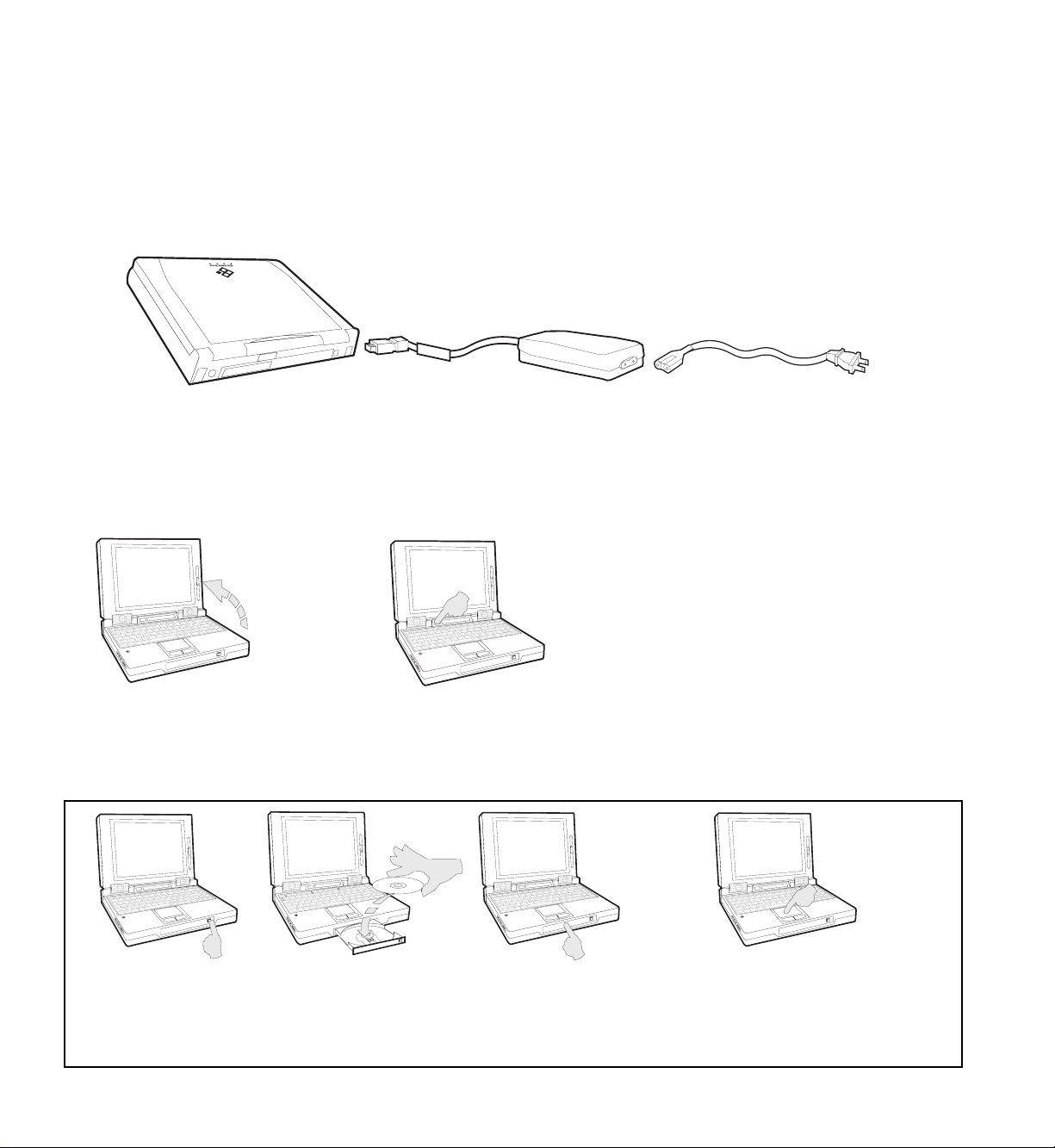
Your First Solo Flight
By now you’ve unpacked your Gateway 2000 Solo™ Multimedia Notebook, and you’re just a few
steps from really taking off.
1. If you haven’t done so already, take the time now to connect your unit to an AC power
source as shown below.
The unit
(Use AC power as the battery in your unit is probably dead. An installed battery automatically charges itself, however, as long as the unit is connected to AC power. In order to
optimize the battery’s life and performance, allow it to charge overnight and then completely
discharge it through normal use. Do this twice for best results.)
2. Slide the
cover latch to
the right to
open the unit.
5. Your system is now ready to fly. Continue navigating your own path, or, if the CD-ROM
drive is installed, follow the steps below to take a quick ride with the Gateway 2000 Solo
System CD.
The AC adapter The AC power cord
3. Press the
power
button to
turn the unit
on.
4. The Windows® 95 logo
appears on the screen.
(Windows® for Workgroups
users must type win at the
C: prompt and press Enter.)
A. Press the eject
button on the
CD-ROM drive.
B. Insert the Gateway
2000 Solo System
CD.
C. Close the drive
tray.
D. Slide a finger on the pad to move
the cursor onto the MEETSOLO
icon in the CD’s directory. Tap
twice to double-click the icon.
Page 3

Contents
Legal notices........................................................................................................................................ 2
Specifications....................................................................................................................................... 4
Outside the Notebook ......................................................................................................................... 6
Front view........................................................................................................................... 6
Back view ........................................................................................................................... 6
Bottom view ....................................................................................................................... 7
Left side view...................................................................................................................... 7
Inside the Notebook............................................................................................................................ 8
Status display bar ................................................................................................................ 8
Keyboard............................................................................................................................. 9
EZ Pad pointing device ..................................................................................................... 11
Built-in microphone/stereo speakers................................................................................. 11
Display .............................................................................................................................. 12
Power ................................................................................................................................................. 13
AC power.......................................................................................................................... 13
Battery power ...................................................................................................................13
Bridge battery ................................................................................................................... 15
Starting, Stopping, and Restarting ................................................................................................. 15
Standby mode ................................................................................................................... 16
Suspend mode................................................................................................................... 16
Rebooting.......................................................................................................................... 16
Modular Option Bay ........................................................................................................................ 17
CD-ROM Drive ................................................................................................................ 18
Floppy Disk Drive............................................................................................................. 18
External Floppy Drive ...................................................................................................................... 19
Hard Disk Drive................................................................................................................................ 19
PCMCIA Cards ................................................................................................................................ 21
Memory.............................................................................................................................................. 22
Connections ....................................................................................................................................... 23
IR module ......................................................................................................................... 23
Docking bar ...................................................................................................................... 23
Setup Menus...................................................................................................................................... 25
Main Setup Menu.............................................................................................................. 25
Password Setup Menu ...................................................................................................... 26
Port Assignment Menu ..................................................................................................... 27
Power Management Menu ................................................................................................ 28
Miscellaneous Menu ......................................................................................................... 29
Keyboard Setup Menu ...................................................................................................... 29
Troubleshooting ................................................................................................................................ 30
Index .................................................................................................................................................. 32
Page 4
The Gateway 2000
™
SOLO
Multimedia Notebook
User’s Guide
Page 5

Legal notices
Gateway 2000 Solo™ Multimedia Notebook
User's Guide
Copyright © 1995
All rights reserved
This book is protected by copyright and all rights are
reserved. No part of it may be reproduced or transmitted
by any means or in any form without prior written consent
from Gateway 2000.
The information in this manual has been carefully checked
and is believed to be accurate. However, Gateway 2000
assumes no responsibility for any inaccuracies that may be
contained in this manual. In no event will Gateway 2000
be liable for direct, indirect, special, incidental, or consequential damages resulting from any defect or omission in
this manual, even if advised of the possibility of such
damages.
In the interest of continued product development, Gateway 2000 reserves the right to make improvements in this
manual and the products it describes at any time, without
notice or obligation.
Trademark acknowledgments
Gateway 2000, The Gateway 2000 Solo logo, cow spot
motif, and motto “You’ve got a friend in the business” are
registered trademarks of Gateway 2000. EZ Pad is a trademark of Gateway 2000. IBM, PC/AT, and PS/2 are registered trademarks of International Business Machines Corporation. Intel is a registered trademark of Intel Corporation. Microsoft, MS, MS-DOS, Windows, and Windows 95
are registered trademarks of Microsoft Corporation. XJACK
is a trademark of the Megahertz Corp. Novell and NetWare
are trademark of Novell, Inc. PostScript is a trademark of
Adobe Systems Inc. All other product names mentioned
herein are used for identification purposes only, and may
be the trademarks or registered trademarks of their respective companies.
FCC statement
NOTE: This is a Class B Digital Device. This equipment has
been tested and found to comply with the limits for a Class
B digital device pursuant to Part 15 of the FCC Rules.
These limits are designed to provide reasonable protection
against harmful interference in a residential installation.
Gateway 2000®
610 Gateway Drive
North Sioux City, SD 57049 USA
This equipment generates, uses, and can radiate radio
frequency energy and, if not installed and used in accordance with the instructions, may cause harmful interference to radio communications. However, there is no guarantee that interference will not occur in a particular installation. If this equipment does cause harmful interference to
radio or television reception, which can be determined by
turning the equipment off and on, the user is encouraged
to try to correct the interference by one of more of the
following measures:
❑ Reorient or relocate the receiving antenna
❑ Increase the separation between the equipment and
receiver
❑ Connect the equipment into an outlet on a circuit
different from that to which the receiver is connected
❑ Consult an experienced radio/TV technician for help.
Caution: Changes or modifications not expressly approved
by the party responsible for compliance could void the
user's authority to operate the equipment.
To meet FCC requirements, shielded cables and power
cords are required to connect this device to a personal
computer or other Class B certified device.
Cautions and warnings
CAUTION: Danger of explosion if battery is incorrectly replaced.
Replace only with the same or equivalent type recommended by
the manufacturer. Dispose of used batteries promptly and according to the manufacturer’s instructions.
ATTENTION: Il y a danger d’explosion s’il y a replacement incorrect de la batterie. Remplacer uniquenment avec une batteries du
meme type ou d’un type recommande par le constructeur. Mettre
rebut les batteries usagees conformement aux instructions du
fabricant.
VORSICHT: Explosionsgefahr bei unsachgemäßem Batteriewechsel.
Originalbatterien nur durch gleiche oder vom Hersteller empfohlene
Batterien ersetzen. Gebrauchte Batterien an Gateway 2000
zurücksenden.
ADVARSEL: Eksplosjonsfare ved feilaktig skifte av batteri. Benytt
samme batteritype eller en tilsvarende type anbefalt av
apparatfabrikanten. Brukte batterier kasseres i henhold til
fabrikantens instruksjoner.
Page 6
CAUTION: This equipment uses a grounded power cable. Do not
attempt to defeat the grounding prong. Do not remove the grounding prong. If you use a three-prong adapter, be sure to connect the
ground wire to a good ground.
Replace the cord if it becomes damaged. U.S. and Canadian replacement cords must be UL-approved (CSA certified in Canada)
type SPT-2, 18 AWG, 2-conductor cord with permanently attached
NEMA type 5-15P plug at one end and a permanently attached
connector body on the other. Cord length may not exceed 15 feet.
Outside the U.S. and Canada the cord must be rated for at least
250VAC at 10 amps, and must indicate international safety agency
approval. The plug must be a type appropriate for the country of
use.
Obtain replacement cords at an authorized service center. The
replacement must be of the same type and voltage rating as the
original cord.
VORSICHT: Diese Ausrüstung verwendet ein geerdetes Netzkabel.
Den Erdungskontakt unter keinen Umständen umgehen oder
entfernen. Bei Verwendung eines dreipoligen Adapters den
Erdungsdraht stets an geprüften Erdungskontakt anschließen.
Beschädigte Kabel ersetzen. Ersatzkabel in den USA und Kanada
müssen folgende Bedingungen erfüllen: UL-anerkannter (in Kanada
CSA-zertifizierter) SPT-2 Typ, 18 AWG, 2-Leiter-Kabel mit fest
installiertem NEMA-Typ-5-15P-Stecker und fest installierter
Anschlußdose am anderen Ende, max. 4,57 m Länge. Außerhalb
der USA und Kanada gelten folgende Bedingungen: Kabel für
mindestens 250 V Wechselstrom bei 10 A, anerkannt durch
internationale Sicherheitsbehörde, landesspezifischer Stecker.
Ersatzkabel nur im Fachhandel erwerben. Nur Ersatzkabel des
gleichen Typs und für die gleiche Spannung (Voltzahl) wie das
Originalkabel verwenden.
WARNING: Always plug the cord into an easily accessible outlet
near the equipment so that unplugging the cord is an easy way to
shut off power.
Do not attempt to disassemble the AC adapter. The AC
adapter has no user-replaceable or -serviceable parts inside. The AC
adapter has dangerous voltages that can cause serious personal
injury or death. Return defective AC adapters to Gateway 2000.
The AC adapter is intended for use with a computer. Both must
meet EN 60950.
ACHTUNG: Netzkabel stets in eine gut zugängliche Steckdose
nahe der Ausrüstung einstecken, um durch einfaches Ziehen des
Steckers jederzeit die Stromversorgung unterbrechen zu können.
Den Adapter unter keinen Umständen auseinanderbauen. Der
Adapter enthält keine vom Benutzer zu ersetzenden oder zu
wartenden Bestandteile. Die Spannung im Adapter kann beim
Auseinanderbau zu Verletzungen oder Tod führen. Beschädigte
Adapter an Gateway 2000 zurücksenden.
Der Adapter ist für den Gebrauch mit einem Computer bestimmt.
Adapter und Computer müssen die Norm EN 60950 erfüllen.
Environmental considerations
Your Gateway 2000 Solo has been engineered to provide many
years of reliable service. However, you should give it the same
reasonable care and protection that you would any other electronic
equipment. Damage caused by dropping the Gateway 2000 Solo,
impact with another object, or immersion in liquids is not covered
by the warranty. Never expose the Gateway 2000 Solo to rain,
snow, or moisture. Avoid locations with high levels of dirt, dust, or
smoke.
CAUTION: DO NOT OPEN. NO USER SERVICEABLE PARTS INSIDE
ATTENTION: NE OUVRIER PAS. PARTIS RÉPARABLES UNIQUEMENT Á L'USINE
VORSICHT: NICHT ÖFFNEN. ENTHÄLT KEINE VOM BENUTZER ZU
WARTENDEN BESTANDTEILE
Colophon
This manual was created electronically with a Gateway 2000 P5100 computer system, MS-DOS 6.22, Windows for Workgroups
3.11, PageMaker 5.0, CorelDraw 5.0, Adobe Type Manager 2.6,
and Adobe Postscript fonts including Stone Sans, Eras Book, Times
New Roman, Tekton, Myriad Headline, Insignia, Gill Sans, and
Zaph Dingbats.
This document is printed on recycled paper, using our
natural resources efficiently and wisely — meeting the
minimum 50% waste paper requirements established by
the Federal EPA in its guidelines for recycled paper
products.
Printed in the United States of AmericaPrinted in the United States of America
Printed in the United States of America
Printed in the United States of AmericaPrinted in the United States of America
Gateway 2000
Gateway 2000 Solo Multimedia Notebook
User’s Guide
Part # SYSMAN017AAUS
9/95
Page 7

4 The Gateway 2000 Solo Multimedia Notebook
Specifications
(Specifications are subject to change without notice or obligation.)
Dimensions (W × D × H) 11.8" × 8.8" × 2.0" (300mm x 223.5mm x 51mm)
Weight approx. 6.3 lbs with battery
Keyboard 86 keys, 100% scale; provides same functions as standard Windows 95 AT keyboard
Screen Backlit active-matrix LCD: 10.2" diagonal (207.4mm x 155.5mm); 640 x 480 x 256
VGA resolution; supports virtual screen to 1024 x768; 0.324mm dot pitch; 70:1
contrast ratio
Backlit active-matrix LCD: 10.4" diagonal (211.2mm x 158.4mm); 800 x 600 x 256
SVGA resolution; supports virtual screen to 1024 x768; 0.264mm dot pitch; 100:1
contrast ratio
Video 1MB video memory; C&T 65545 controller, VESA local bus with Windows accelera-
tion; Video port supports: 640 x 480 x 16–64K colors, 800 x 600 x 16 or 256 colors,
1024 x 768 x 16 or 256 colors
Mouse/Pointer EZ Pad integrated pointer; PS/2-type connector for external mouse
CPU Intel P54CLM-75 or P54CLM-90 low power Pentium Processor
Cache 16K in CPU; 256K pipelined burst synchronous external
CPU speed 75 or 90MHz
BIOS 256K; includes configuration utility with password security and power management
RAM type 70ns 3.3V low power DRAM
RAM capacity 8MB on board, expandable to 16, 24, or 40MB by using a pair of 4, 8, or 16MB modules
(subject to availability)
Expansion slots Two PCMCIA Type II slots (or stacked as one Type III slot) with card ejectors;
supports hot-swapping of most cards
I/O ports DB25 floppy/parallel port; DB9 serial port; PS/2 external keyboard/mouse connector;
docking bar connector, video connector, IR port
Modular bay Internal 1.44MB 3.5 inch floppy drive or 5 inch 2x CD-ROM drive
Hard disk drive 340MB, 540MB, 720MB or 1.2GB IDE removeable drive, depending on system
Accessories AC adapter; IR (infrared) module; Lithium battery; Docking bar, External floppy disk
drive, Optional leather carrying case
Page 8

User’s Guide 5
PCMCIA option 2400/9600 data/fax modem; 14,400 data/fax modem; twisted pair or thinnet (BNC)
Ethernet network; token ring network; other cards available from other sources
Environment 10-35° C; 10-95% noncondensing relative humidity
AC adapter Requires 100-240 VAC, 0.88-0.46A nominal: adapter powers system and charges
battery simultaneously
Battery pack 14.4DC, 2700mAh lithium battery: batteries can be “hot-swapped” without rebooting.
Recharges in or out of system. Conforms to APM 1.1
Permanent internal NiMH battery maintains system memory for about one-half day
with battery pack removed
Battery life 38.88 watt-hours; 2.5 to over 4 hours in typical usage under Windows®; fully charged
battery lasts about three weeks in Suspend mode
Charging cycle Varies depending on battery condition; full charge usually takes about two and one-half
hours
Certification FCC Class B, UL, CSA, TUV (approved to IEC950/EN60950),
Page 9
6 The Gateway 2000 Solo Multimedia Notebook
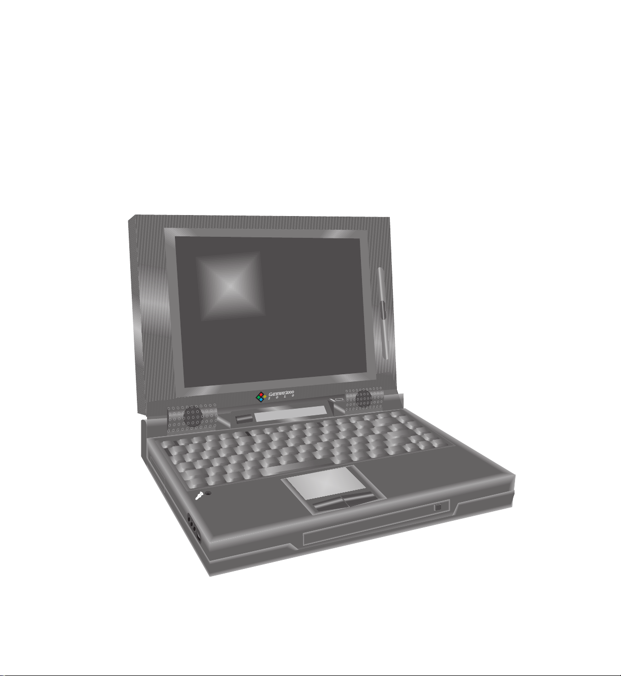
Outside the Notebook
The Gateway 2000 Solo Multimedia Notebook is designed to provide the multimedia functionality of a full-size desktop system along with the convenience of a
lightweight portable. Even if you are already using the unit, we recommend you take
a few moments to familiarize yourself with its many functions and features.
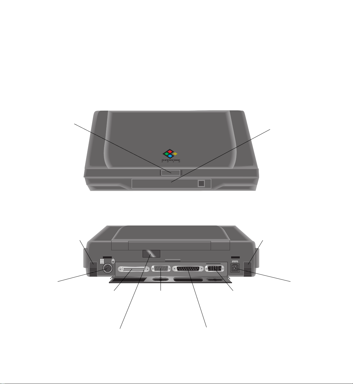
Front view
Cover latch:Cover latch:
Cover latch:
Cover latch:Cover latch:
slide to the right
to release the lid
and open the
unit.
Back view
(port cover flipped down)
Flip down foot:Flip down foot:
Flip down foot:
Flip down foot:Flip down foot:
flip it down to
tilt the unit for
more comfort.
PS/2PS/2
PS/2
PS/2PS/2
port:port:
port:
port:port:
connect a
mouse or
keyboard
here. (See
pages 9
and 11.)
Docking barDocking bar
Docking bar
Docking barDocking bar
port (120-pin):port (120-pin):
port (120-pin):
port (120-pin):port (120-pin):
connect the
docking bar here.
(See page 23.)
IR port:IR port:
IR port:
IR port:IR port:
place the IR module so that it’s
receiver/transmitter can “see”
this port. (See page 23.)
Serial port:Serial port:
Serial port:
Serial port:Serial port:
connect any serial
device here.
VGA port:VGA port:
VGA port:
VGA port:VGA port:
connect any
standard
monitor here.
(See page 12.)
Floppy/Parallel port:Floppy/Parallel port:
Floppy/Parallel port:
Floppy/Parallel port:Floppy/Parallel port:
connect external floppy disk drive
or any parallel device here. (See
page 19.)
Modular optionModular option
Modular option
Modular optionModular option
bay:bay:
bay:
bay:bay:
houses internal
floppy disk drive
or CD-ROM drive.
(See page 17.)
Flip down foot:Flip down foot:
Flip down foot:
Flip down foot:Flip down foot:
flip it down to
tilt the unit for
more comfort.
ACAC
AC
ACAC
connector:connector:
connector:
connector:connector:
connect AC
adapter
here. (See
page 13.)
Page 10
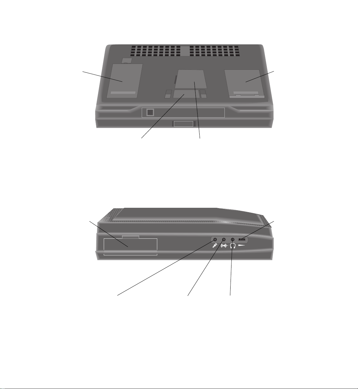
Bottom view
User’s Guide 7
RemovableRemovable
Removable
RemovableRemovable
lithium ionlithium ion
lithium ion
lithium ionlithium ion
battery:battery:
battery:
battery:battery:
can be removed
and charged
separately from
the unit. (See
pages 13 and
14.)
Modular drive bayModular drive bay
Modular drive bay
Modular drive bayModular drive bay
release access panel:release access panel:
release access panel:
release access panel:release access panel:
open to access release latch for
removing drive or cover from
drive bay. (See page 17.)
Left side view
PCMCIA doorPCMCIA door
PCMCIA door
PCMCIA doorPCMCIA door
(reset button):(reset button):
(reset button):
(reset button):(reset button):
flip it down to
reveal flush
PCMCIA slots and
reset button.
(See pages 21
and 16.)
Removable hardRemovable hard
Removable hard
Removable hardRemovable hard
can be removed
Expansion memory access panel:Expansion memory access panel:
Expansion memory access panel:
Expansion memory access panel:Expansion memory access panel:
open to install or replace memory
modules. (See page 22.)
Volume control:Volume control:
Volume control:
Volume control:Volume control:
volume of built-in
headphone jack.
does not affect
the volume of the
Line Out jack on
the docking bar.)
disk drive:disk drive:
disk drive:
disk drive:disk drive:
from the unit.
(See pages 19
and 20.)
turn to adjust
speakers or
(This control
Microphone jack:Microphone jack:
Microphone jack:
Microphone jack:Microphone jack:
connect external
microphone here.
(Using this
disables the builtin microphone.)
Line input jack:Line input jack:
Line input jack:
Line input jack:Line input jack:
connect line from external
audio source here.
Headphone jack:Headphone jack:
Headphone jack:
Headphone jack:Headphone jack:
connect headphones
or speakers here.
(Using this disables
the built-in speakers.)
Page 11
8 The Gateway 2000 Solo Multimedia Notebook
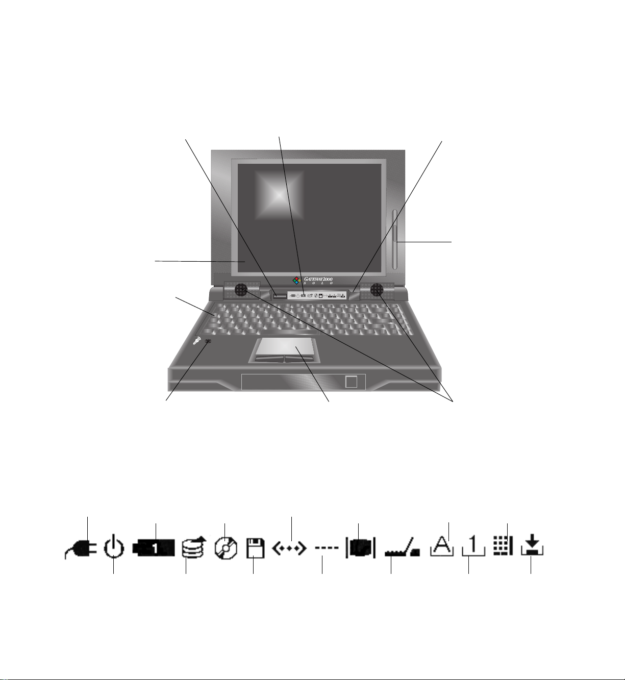
Inside the Notebook
Power button:Power button:
Power button:
Power button:Power button:
Press once to activate
Suspend or Resume
mode.
10” color display:10” color display:
10” color display:
10” color display:10” color display:
Full-size keyboard:Full-size keyboard:
Full-size keyboard:
Full-size keyboard:Full-size keyboard:
Specially designed for
use with Windows® 95.
(See page 9.)
Status display bar:Status display bar:
Status display bar:
Status display bar:Status display bar:
indicates which devices and functions
are active. (See below.)
Battery charge light:Battery charge light:
Battery charge light:
Battery charge light:Battery charge light:
changes color to indicate
battery charge status:
Yellow=charging;
Green=charged;
Red=charging error.
(See page 14.)
Screen brightnessScreen brightness
Screen brightness
Screen brightnessScreen brightness
control:control:
control:
control:control:
slide up or down to
adjust brightness
of screen. (See
page 12.)
Built-in microphone:Built-in microphone:
Built-in microphone:
Built-in microphone:Built-in microphone:
suitable for recording sounds.
(See page 11.)
Status display bar
AC power:AC power:
AC power:
AC power:AC power:
lit when unit is
operating on AC
power.
Standby:Standby:
Standby:
Standby:Standby:
lit when unit is in
standby mode.
(See page 16.)
Battery power:Battery power:
Battery power:
Battery power:Battery power:
lit when unit is
operating on
battery power.
Hard disk:Hard disk:
Hard disk:
Hard disk:Hard disk:
lit when hard
drive is ac-
cessed.
EZ Pad™ pointing device:EZ Pad™ pointing device:
EZ Pad™ pointing device:
EZ Pad™ pointing device:EZ Pad™ pointing device:
controls the cursor like a mouse. (See page 11.)
CD-ROM:CD-ROM:
CD-ROM:
CD-ROM:CD-ROM:
lit when CDROM drive is
accessed.
Floppy disk:Floppy disk:
Floppy disk:
Floppy disk:Floppy disk:
lit when internal
floppy drive is
accessed.
IR port:IR port:
IR port:
IR port:IR port:
lit when IR port
is enabled.
Serial port:Serial port:
Serial port:
Serial port:Serial port:
lit when serial
port is enabled.
Monitor switch:Monitor switch:
Monitor switch:
Monitor switch:Monitor switch:
lit when external
monitor port is
active.
Docking bar:Docking bar:
Docking bar:
Docking bar:Docking bar:
lit when docking
bar is con-
nected.
Stereo speakers:Stereo speakers:
Stereo speakers:
Stereo speakers:Stereo speakers:
provide stereo sound
Caps Lock:Caps Lock:
Caps Lock:
Caps Lock:Caps Lock:
lit when Caps
Lock is enabled.
(See page 10.)
Num Lock:Num Lock:
Num Lock:
Num Lock:Num Lock:
lit when Num
Lock is enabled.
(See page 10.)
(See page 11.)
Pad Lock:Pad Lock:
Pad Lock:
Pad Lock:Pad Lock:
lit when Pad
Lock is enabled.
(See page 10.)
Scroll Lock:Scroll Lock:
Scroll Lock:
Scroll Lock:Scroll Lock:
lit when Scroll
Lock is enabled.
(See page 10.)
Page 12
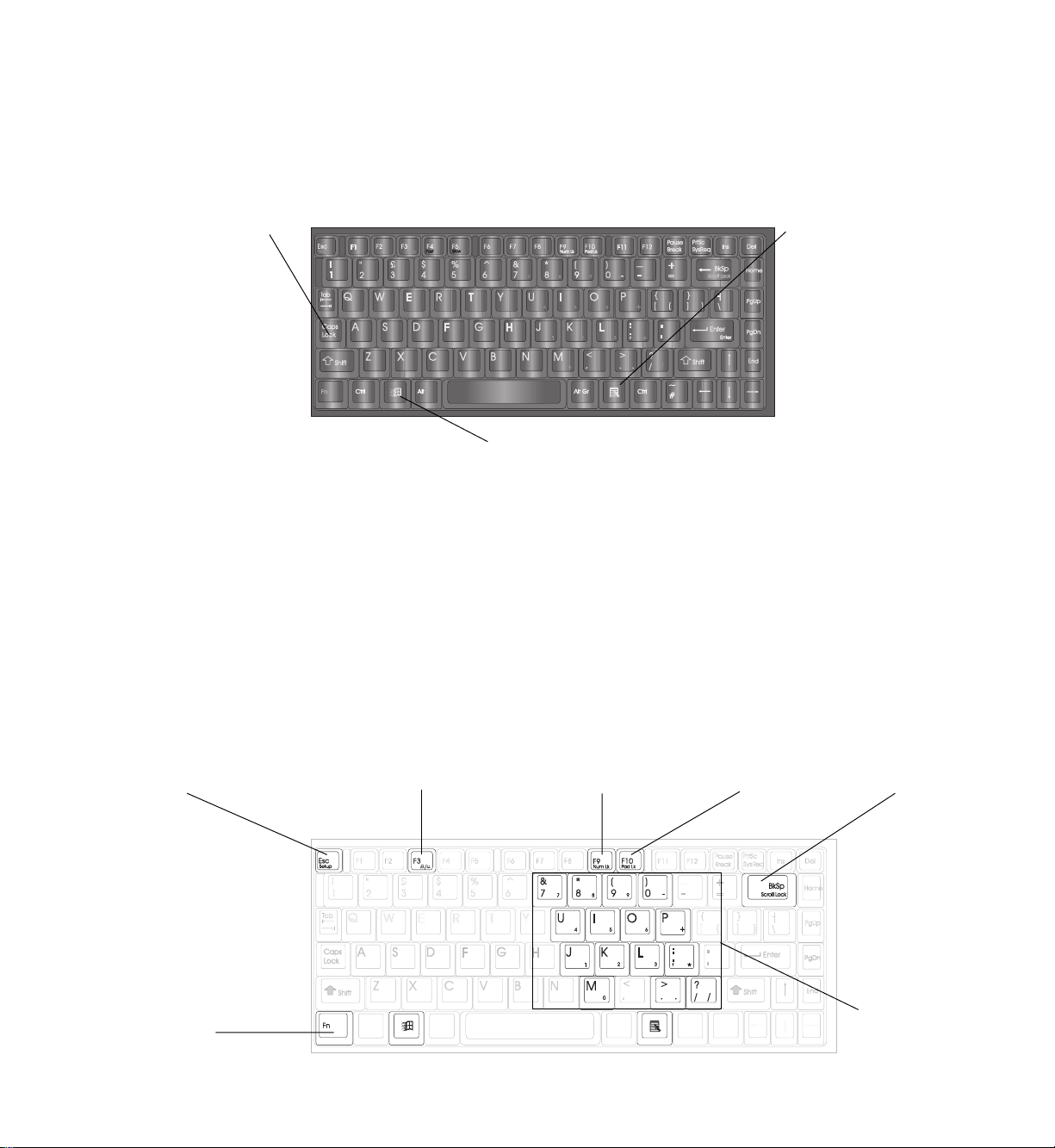
Keyboard
User’s Guide 9
The system features a specially-designed, 86-key keyboard. In order to provide the
full functionality of a 101-key keyboard, many of these keys have been assigned
special alternate functions, including shortcut keys for Windows® 95.
Caps Lock key:Caps Lock key:
Caps Lock key:
Caps Lock key:Caps Lock key:
press to lock
letter keys in
uppercase mode.
(When active,
Caps Lock icon
appears in
status display
bar icon. See
page 8.)
An external keyboard may be attached to the unit through the PS/2 port on the
back of the unit (See page 6.) or the PS/2 (keyboard) port on the docking bar. (See
page 24.)
Special function keys
The keys with blue labels perform special functions when activated. The status
display bar shows individual icons for the Monitor Switch, Num Lock, Pad Lock,
and Scroll Lock keys when each is activated. (See page 8.)
Windows 95 start button key:Windows 95 start button key:
Windows 95 start button key:
Windows 95 start button key:Windows 95 start button key:
press to automatically click the Start button in
Windows 95. (See Windows 95 documentation.)
Windows 95Windows 95
Windows 95
Windows 95Windows 95
menu key:menu key:
menu key:
menu key:menu key:
press to access
menus within a
Windows 95
application. (See
Windows 95
documentation.)
SetupSetup
Setup
SetupSetup
key:key:
key:
key:key:
Fn (function)Fn (function)
Fn (function)
Fn (function)Fn (function)
key:key:
key:
key:key:
Monitor switchMonitor switch
Monitor switch
Monitor switchMonitor switch
key:key:
key:
key:key:
Num LockNum Lock
Num Lock
Num LockNum Lock
key:key:
key:
key:key:
Pad LockPad Lock
Pad Lock
Pad LockPad Lock
key:key:
key:
key:key:
Scroll LockScroll Lock
Scroll Lock
Scroll LockScroll Lock
key:key:
key:
key:key:
FunctionFunction
Function
FunctionFunction
keypad:keypad:
keypad:
keypad:keypad:
Page 13

10 The Gateway 2000 Solo Multimedia Notebook
Key To activate Function
Fn press with blue label key activates alternate functions of blue label keys
(See Pad Lock below.)
Setup press with Fn key displays Setup Menus (See page 25.)
Monitor switch press with Fn key switches between monitor options: internal, external, or
both
Num Lock press with Fn key activates numeric keypad mode of function keypad
Pad Lock press with Fn key locks Fn down during use with Num Lock or Scroll Lock
Scroll Lock press with Fn key activates cursor-control mode of function keypad
Function keypad (See below.) functions as either numeric or cursor-control keypad
Function keypad
The keys of the function keypad produce the following:
❏ standard lowercase letters, numerals, and punctuation when pressed alone
❏ standard uppercase letters and symbols when pressed with the Shift key
❏ numerals and symbols when pressed with the Fn and Num Lock keys
❏ cursor movements when pressed with Fn and Scroll Lock keys
(See the chart below for details.)
Key Key + Shift Key + Num Lock Key + Scroll Lock (cursor control)
7 & 7 Home
8 * 8 Up arrow
9 ( 9 Page Up
0 ) - (no effect)
u U 4 Left arrow
i I 5 (no effect)
o O 6 Right arrow
p P + (no effect)
j J 1 End
k K 2 Down arrow
l L 3 Page Down
; : * (no effect)
m M 0 (no effect)
. > . Delete
/ ? / (no effect)
Page 14

EZ Pad pointing device
Like a mouse, the EZ Pad pointing device controls the movements of the cursor on
the screen. Press a finger against the pad and move it in the direction you want the
cursor to move.
Pad:Pad:
Pad:
Pad:Pad:
move finger on pad
to control cursor
movements.
To click on something: position the cursor on the item and tap on the pad once.
To double-click on something: position the cursor on the item and tap on the pad
twice.
User’s Guide 11
Buttons:Buttons:
Buttons:
Buttons:Buttons:
use in place
of left and
right mouse
buttons.
To drag and drop on something: position the cursor on the item, tap on the pad
twice and slide your finger (without lifting it) to reposition the cursor, and release.
An external mouse may be attached to the unit through the PS/2 port on the back of
the unit (See page 6.) or the PS/2 (mouse) port on the docking bar. (See page 24.)
Built-in microphone/stereo speakers
Because of their proximity to each other, the built-in microphone may cause feedback in the internal stereo speakers if both are used at the same time. (For this reason,
your unit was shipped with the built-in microphone turned off. It may be turned on
through your unit’s audio control panel.) If you encounter this feedback problem, it
may be remedied by turning the volume down or by using an external microphone or
external speakers. (See the audio connections on page 7.)
Page 15

12 The Gateway 2000 Solo Multimedia Notebook
Display
The system features a built-in, backlit, active-matrix, color display. This display is
either a 10.2 inch VGA display or a 10.4 inch SVGA display. Each of these displays
provides sharp, clear color and resolution.
Backlit display:Backlit display:
Backlit display:
Backlit display:Backlit display:
tilt the unit’s cover
forward or backward to
adjust viewing angle.
BrightnessBrightness
Brightness
BrightnessBrightness
control:control:
control:
control:control:
slide up or down
to adjust screen
brightness.
Tilt the unit’s entire cover forward or backward to adjust the viewing angle. A
sliding control on the right of the screen controls brightness. (VGA displays also
have a contrast control located directly below the brightness control.)
Because the display is an active-matrix display, small dots of color may occasionally
appear on the screen. Do not worry: this is normal for active-matrix screens and does
not affect the overall screen image.
NOTE: If your unit displays an unchanging image for an extended period of time,
that image may remain on the screen for a while as a slight shadow. Although this
shadow is temporary and will disappear eventually, a screen saver program should be
used to maintain optimum image quality.
An external monitor may be attached to the unit through the VGA port located on
the back of the unit (See page 6.) or on the docking bar. (See page 24.) If you attach
an additional monitor, use the Monitor Switch key to specify which display is active
(See page 10.) and check the Boot Display function on the Main Setup Menu. (See
pages 25 and 26.) When an external monitor is active, the monitor switch icon lights
in the status display bar. (See page 8.)
Page 16

Power
AC power
User’s Guide 13
The unit draws power from either a direct AC connection or its own rechargeable
battery. To optimize the system’s use of power, enter the Power Managment Menu
in the Setup Menus. (See page 25.)
We recommend you use the AC adapter whenever possible to provide the unit with
a constant supply of power and simultaneously keep the battery charged. (See
“Charging/discharging the battery” below for details.) The proper method for
connecting the AC power to the unit is shown below:
Step 1:Step 1:
Step 1:
Step 1:Step 1:
connect the AC adapter to
the unit’s AC connector.
Battery power
When you first receive the battery, it is installed in the system but not charged. We
recommend that you completely charge and discharge the battery twice as soon as
possible, as this improves the accuracy of the unit’s battery power gauge and
optimizes the battery’s life and performance.
Charging/discharging the battery
The battery must be connected to an AC power source for about 2 and one-half
hours to charge completely. The unit can run on a fully charged battery for about 35 hours of normal use before the battery needs recharging. When the battery level
gets low, the battery icon in the status display bar blinks. (See page 8.)
Step 2:Step 2:
Step 2:
Step 2:Step 2:
connect the power cord
to the AC adapter.
Step 3:Step 3:
Step 3:
Step 3:Step 3:
plug the power cord into an
electrical outlet.
Page 17

14 The Gateway 2000 Solo Multimedia Notebook
If the battery is installed in the unit and the unit is connected to AC power (See “AC
power” on the previous page.), it automatically charges, even if the unit is in use.
While the battery charges, the battery charger light (See page 8.) glows yellow, and
when it is fully charged, the light glows green. (If the battery charger light glows red,
a charging failure has occurred. Check connections and try again.)
Removing the battery
The battery may also be charged independently of the unit. Simply remove the
battery from the unit’s case as shown below and connect it directly to the AC
adapter.
Battery latch:Battery latch:
Battery latch:
Battery latch:Battery latch:
Battery:Battery:
Battery:
Battery:Battery:
Step 1:Step 1:
Step 1:
Step 1:Step 1:
Disconnect the AC adapter,
turn the unit over, and slide
the battery latch away from
the battery.
Step 3:Step 3:
Step 3:
Step 3:Step 3:
Lift the battery up and away
from the unit.
Step 2:Step 2:
Step 2:
Step 2:Step 2:
While holding the latch, place
a fingertip in the indention
and lift the edge of the
battery up.
Step 4:Step 4:
Step 4:
Step 4:Step 4:
Connect the AC adapter to
the battery’s AC connector.
AC connector:AC connector:
AC connector:
AC connector:AC connector:
Page 18

Bridge battery
Beneath the unit’s hard disk drive bay lies the bridge battery. This rechargeable 3.6V
battery provides power for certain functions when the unit is not connected to a
power source (AC or battery). It automatically charges while the unit uses either
power source and is designed to last for the life of the unit. However, the instructions
below detail the procedure for removal and replacement if necessary:
User’s Guide 15
Hard disk drive:Hard disk drive:
Hard disk drive:
Hard disk drive:Hard disk drive:
Battery’sBattery’s
Battery’s
Battery’sBattery’s
connector:connector:
connector:
connector:connector:
Step 1:Step 1:
Step 1:
Step 1:Step 1:
Remove the hard disk drive as
shown on page 20.
Step 3:Step 3:
Step 3:
Step 3:Step 3:
Carefully lift the battery out of
its compartment and slide its
connector out from the unit’s
connector.
Step 2:Step 2:
Step 2:
Step 2:Step 2:
Locate the bridge battery
under the HDD bay.
Step 4:Step 4:
Step 4:
Step 4:Step 4:
Slide the replacement battery’s
connector into the unit’s connector
and place battery back into compartment. Replace hard disk drive.
Bridge battery:Bridge battery:
Bridge battery:
Bridge battery:Bridge battery:
Unit’sUnit’s
Unit’s
Unit’sUnit’s
connector:connector:
connector:
connector:connector:
Starting, Stopping, and Restarting
After the system is connected to a power source, it can be started by opening the
cover and pressing the power button.
Power button:Power button:
Power button:
Power button:Power button:
press once to
turn the unit on.
The unit may likewise be shut down by pressing the power button. This method of
turning off the system is recommended, especially when the unit will not be used for
some time. When using this method to shut down the system, be sure to save all work
before pressing the power button.
Page 19

16 The Gateway 2000 Solo Multimedia Notebook
Standby mode
To conserve the system’s power and resources while it is on, enter the Power
Management Menu (See page 28.) and switch the Standby Timer setting in the User
Settings Menu: Battery to the desired time amount. The unit then goes into Standby
mode if you don’t use the keyboard or EZ Pad for a while: The hard disk drive spins
down, the screen goes blank, and the Standby icon on the status display bar lights.
(See page 8.) After about 10 minutes of Standby mode, the unit automatically shifts
to Suspend mode. Using the keyboard or EZ Pad sends the unit from Standby mode
back to its active mode .
Suspend mode
The system goes into Suspend mode after 10 minutes or so of Standby mode. It also
enters Suspend mode from the active mode if the battery is removed, the cover is
closed, or the power button is pressed. When the unit is in Suspend mode, it appears
to be shut off, but it is actually using a very small amount of power to save your work
for up to three weeks. Of course, work should still be saved to the hard drive as often
as possible, because the Suspend save only lasts as long as the unit is in Suspend
mode. To exit Suspend mode, open the cover and press the power button.
Rebooting
If the system stops responding to the EZ Pad or the keyboard, it has experienced a
“hang.” Generally, a hang can be fixed by one of the following procedures:
❏ Ctrl+Alt+Del: Press the Ctrl, Alt, and Del keys simultaneously. Try this
procedure (also called a “warm boot”) before attempting the others below.
❏ Fn+Alt+Del: Press the Fn, Alt, and Del keys simultaneously. This procedure
(also called a “cold boot”) is similar to pressing the reset button on a desktop
computer.
❏ Hardware Reset button: If the keystrokes above don’t have any effect,
press this button (located inside the PCMCIA slot on the left side of the unit)
to restart the unit.
Left side view of the system
Hardware resetHardware reset
Hardware reset
Hardware resetHardware reset
button:button:
button:
button:button:
press once to reboot
the unit.
Page 20

Modular Option Bay
The Gateway 2000 Solo PC features a modular option bay located directly beneath
the cover latch. This bay accepts the modular CD-ROM drive, the modular internal
floppy disk drive, or the modular bay cover when neither drive is installed. The unit
houses either drive, but only one at a time. (The bay cover is recommended for use
when neither drive is installed and total carrying weight of the unit is an issue.)
Cover latch:Cover latch:
Cover latch:
Cover latch:Cover latch:
To switch between drives, remove the installed drive (or bay cover) from the unit’s
modular bay as shown below and replace it with a different drive.
User’s Guide 17
Modular option bay:Modular option bay:
Modular option bay:
Modular option bay:Modular option bay:
(CD-ROM drive is
shown installed).
Modular bayModular bay
Modular bay
Modular bayModular bay
covercover
cover:
covercover
Bay accessBay access
Bay access
Bay accessBay access
panel:panel:
panel:
panel:panel:
Release latchRelease latch
Release latch:
Release latchRelease latch
Step 1:Step 1:
Step 1:
Step 1:Step 1:
Turn the unit off and flip it
over. Locate the modular bay
release access panel and flip
the panel open.
Step 3:Step 3:
Step 3:
Step 3:Step 3:
Turn the new drive (or cover) upside down*, align the grooves on
its sides with the rails in the bay, and push the drive into the
bay until the latch locks into place and the access panel can be
closed. Restart the unit.
Step 2:Step 2:
Step 2:
Step 2:Step 2:
Slide the release latch forward
until the drive (or cover) ejects
from the unit. Remove the
drive (or cover).
*The system is upside down at this point, so the drive being installed must be turned
upside down as well.
Page 21

18 The Gateway 2000 Solo Multimedia Notebook
To use CD-ROM and floppy disk drive functions simultaneously, install the modular
CD-ROM drive and connect an external floppy drive to the floppy/parallel port on
the unit or the docking bar. (See “External Floppy Drive” on page 19.)
CD-ROM Drive
To ensure that the system can recognize and read it, the CD-ROM drive must be
already installed when the system is booted up. If the system is on when the drive
is installed, it must be rebooted.
CD-ROM drive:CD-ROM drive:
CD-ROM drive:
CD-ROM drive:CD-ROM drive:
top view from
the front
Open button:Open button:
Open button:
Open button:Open button:
press to open CD tray after installation.
When the CD-ROM drive is installed and active, the CD-ROM drive icon lights in
the status display bar. (See page 8.)
Floppy Disk Drive
To ensure that the system can recognize and read it, the floppy disk drive must be
already installed when the system is booted up. If the system is on when the drive
is installed, it must be rebooted.
Floppy diskFloppy disk
Floppy disk
Floppy diskFloppy disk
drive:drive:
drive: top view
drive:drive:
from the front
CD-ROM drive:CD-ROM drive:
CD-ROM drive:
CD-ROM drive:CD-ROM drive:
top view from
Modular connector:Modular connector:
Modular connector:
Modular connector:Modular connector:
attaches inside the Solo.
drive:drive:
drive: top view
drive:drive:
from the back
the back
Floppy diskFloppy disk
Floppy disk
Floppy diskFloppy disk
Open button:Open button:
Open button:
Open button:Open button:
press to eject floppy diskette.
When the floppy disk drive is installed and active, the floppy disk drive icon lights in
the status display bar. (See page 8.)
Modular connector:Modular connector:
Modular connector:
Modular connector:Modular connector:
attaches inside the Solo.
Page 22

External Floppy Drive
The system accepts an optional external floppy disk drive. This drive connects to the
floppy/parallel port on the back of the unit as shown below. (It also connects to the
floppy/parallel port on the docking bar. See page 24.) This connection requires a
floppy drive cable:
Step 1:Step 1:
Step 1:
Step 1:Step 1:
connect the cable’s parallel connector
to the unit’s (or the docking bar’s)
floppy/parallel port.
When the floppy disk drive is installed and active, the floppy disk drive LED lights on
the external floppy disk drive. (External drives do not affect status display bar icons.)
User’s Guide 19
Step 2:Step 2:
Step 2:
Step 2:Step 2:
connect the cable’s other connector to the floppy drive’s connector
(not shown).
Hard Disk Drive
The system’s hard disk drive (HDD) may be removed from the unit for replacement
or for switching between different hard drives.
Hard disk drive:Hard disk drive:
Hard disk drive:
Hard disk drive:Hard disk drive:
The instructions on the following page detail the procedure for removing and
replacing the hard disk drive:
HDD release latch:HDD release latch:
HDD release latch:
HDD release latch:HDD release latch:
Page 23

20 The Gateway 2000 Solo Multimedia Notebook
Hard disk drive:Hard disk drive:
Hard disk drive:
Hard disk drive:Hard disk drive:
HDD releaseHDD release
HDD release
HDD releaseHDD release
latch:latch:
latch:
latch:latch:
Step 1:Step 1:
Step 1:
Step 1:Step 1:
Turn the unit over and locate
the hard disk drive (HDD) and
its release latch.
Step 3:Step 3:
Step 3:
Step 3:Step 3:
With the release latch up, slide
the hard drive toward the
front of the unit.
Step 2:Step 2:
Step 2:
Step 2:Step 2:
Slide a fingernail between the
hard drive and the release
latch. Grasp the latch and pull
it straight up.
Step 4:Step 4:
Step 4:
Step 4:Step 4:
Grasp the latch and lift the hard drive
up and out of the HDD bay. (The HDD
may need to be slid backwards to free
it from the unit.)
When the hard disk drive is installed and active, the hard disk icon lights in the status
display bar. (See page 8.) The instructions below detail the procedure for installing
or replacing the hard drive:
Step 1:Step 1:
Step 1:
Step 1:Step 1:
Gently lower the drive into the
unit’s HDD bay.
Step 3:Step 3:
Step 3:
Step 3:Step 3:
Slide the drive all the way to
the back of the HDD bay.
Step 2:Step 2:
Step 2:
Step 2:Step 2:
Slide the drive toward the front of the
HDD bay to assure proper placement.
Step 4:Step 4:
Step 4:
Step 4:Step 4:
Press the release latch into place. (If
the latch does not easily snap into
place, adjust the position of the drive.)
Page 24

PCMCIA Cards
The system’s PCMCIA slots are located behind the PCMCIA door on the left side of
the unit. These slots may be used as two Type II slots or as one Type III slot. Since
these are flush slots, the door can be shut even when a PCMCIA card is installed. The
system is preconfigured to accept most PCMCIA cards automatically: simply plug a
card into the PCMCIA slot as shown below:
PCMCIA door:PCMCIA door:
PCMCIA door:
PCMCIA door:PCMCIA door:
User’s Guide 21
PCMCIA slot:PCMCIA slot:
PCMCIA slot:
PCMCIA slot:PCMCIA slot:
(2 shown).
Eject buttons:Eject buttons:
Eject buttons:
Eject buttons:Eject buttons:
Step 1:Step 1:
Step 1:
Step 1:Step 1:
Flip open the PCMCIA door on
the left side of the unit.
Step 3:Step 3:
Step 3:
Step 3:Step 3:
Locate the PCMCIA slot in
which you wish to install the
card.
Step 2:Step 2:
Step 2:
Step 2:Step 2:
Select a PCMCIA card to
install.
Step 4:Step 4:
Step 4:
Step 4:Step 4:
Slide the card into the slot and
use the device as instructed in its
manual.
To remove a PCMCIA card, simply press the appropriate eject button located to the
right of the PCMCIA slot. Because the system supports “hot-swapping,” one card
can usually be exchanged for another by simple removal and replacement.
Page 25

22 The Gateway 2000 Solo Multimedia Notebook
Memory
The system already has a minimum of 8MB of RAM on board. This memory capacity
can be upgraded by installing memory modules in the unit’s expandable memory
sockets, located on the underside of the unit. These sockets will accept 4, 8, or
16MB modules, but remember: If you upgrade the memory, the same type and
size module must be used in EACH socket! For instance, if you wish to install a
4MB module in one of the sockets, you MUST install an identical module in the
other socket. Memory modules are installed in the memory sockets as shown below:
Memory accessMemory access
Memory access
Memory accessMemory access
panel:panel:
panel:
panel:panel:
Step 1:Step 1:
Step 1:
Step 1:Step 1:
Enter the Main Setup Menu ,
set the power switch to ON/
OFF, and exit saving changes.
(See page 25 and 26.)
Step 3:Step 3:
Step 3:
Step 3:Step 3:
Turn the unit over and lift away
the expansion memory access
panel.
Step 2:Step 2:
Step 2:
Step 2:Step 2:
Press the Power button to
turn the unit off, close the lid,
disconnect the AC power, and
remove the battery.
Step 4:Step 4:
Step 4:
Step 4:Step 4:
Insert two memory modules,
one into each socket. They
must be identical. Close the
unit. (Feel free to re-enter the
Main Setup Menu and change
the power switch back.)
Page 26

Connections
The unit uses a variety of hardware to connect to peripheral devices or to other
computer systems. When the unit connects to another system, that system is called
the “remote system.”
IR module
The IR module uses infrared technology to send signals between the unit and the
remote system. The odd-shaped end of the module (the receiver/transmitter) must be
placed within nine inches of the IR port located on the back of the unit. The flat side
of this end must directly face the IR port. The other end connects to the remote
system’s serial port as shown below:
User’s Guide 23
IR receiver/transmitter:IR receiver/transmitter:
IR receiver/transmitter:
IR receiver/transmitter:IR receiver/transmitter:
point the flat side of this toward
the unit’s IR port and place it
within 9 inches.
When the IR module is active, the IR module icon lights in the status display bar.
(See page 8.)
Docking bar
The docking bar, or port replicator, duplicates many of the connectors and ports
found on the back of the unit as well as a line out jack for audio, a game port, and an
extra PS/2 port. Peripheral devices—such as an external keyboard, mouse, or
joystick—connect to the bar, which then connects to the system.
Unit’s IR port:Unit’s IR port:
Unit’s IR port:
Unit’s IR port:Unit’s IR port:
located on the back
of the unit.
connect this end to the serial port
connector on the remote system.
Typical serial port:Typical serial port:
Typical serial port:
Typical serial port:Typical serial port:
located on the
remote system.
Serial port connector:Serial port connector:
Serial port connector:
Serial port connector:Serial port connector:
Page 27

24 The Gateway 2000 Solo Multimedia Notebook
Lock:Lock:
Lock:
Lock:Lock:
(shown closed)
rotate handle
closed (against
docking bar) to
lock bar to unit.
PS/2 (mouse)PS/2 (mouse)
PS/2 (mouse)
PS/2 (mouse)PS/2 (mouse)
port:port:
port:
port:port:
connect a
mouse here.
PS/2PS/2
PS/2
PS/2PS/2
(keyboard)(keyboard)
(keyboard)
(keyboard)(keyboard)
port:port:
port:
port:port:
connect a
keyboard
here.
Port cover:Port cover:
Port cover:
Port cover:Port cover:
Docking barDocking bar
Docking bar
Docking barDocking bar
port:port:
port:
port:port:
Access door:Access door:
Access door:
Access door:Access door:
Lock:Lock:
Lock:
Lock:Lock:
(shown closed)
rotate handle
closed (against
docking bar) to
lock bar to unit.
AC connector:AC connector:
AC connector:
VGA port:VGA port:
VGA port:
VGA port:VGA port:
connect any
standard
monitor here.
Line out jack:Line out jack:
Line out jack:
Line out jack:Line out jack:
connect stereo
self-powered
speakers here.
Floppy/Parallel port:Floppy/Parallel port:
Floppy/Parallel port:
Floppy/Parallel port:Floppy/Parallel port:
connect floppy disk drive or
any parallel device here.
MIDI/Game port:MIDI/Game port:
MIDI/Game port:
MIDI/Game port:MIDI/Game port:
connect a
joystick or
musical device
here.
AC connector:AC connector:
connect AC
adapter here.
Serial port:Serial port:
Serial port:
Serial port:Serial port:
connect any
serial device
here.
Because the peripherals connect to the unit through the docking bar, the unit
connects to (or disconnects from) them in one step and at only one place: its 120-pin
docking bar port. The docking bar attaches directly to the unit as shown below:
Docking barDocking bar
Docking bar
Docking barDocking bar
port:port:
port:
port:port:
Docking bar’sDocking bar’s
Docking bar’s
Docking bar’sDocking bar’s
connector:connector:
connector:
connector:connector:
Step 1:Step 1:
Step 1:
Step 1:Step 1:
Close the port cover and slide
the small panel (in front of the
docking bar port) to the right.
Step 2:Step 2:
Step 2:
Step 2:Step 2:
Align the docking bar’s connector with the unit’s port. Press
the docking bar to the unit.
Lock:Lock:
Lock:
Lock:Lock:
(shown open)
rotate toward
docking bar to
close. (One on
other side of bar
as well.)
Step 3:Step 3:
Step 3:
Step 3:Step 3:
Rotate the docking bar’s locks
to secure it to the Solo.
Step 4:Step 4:
Step 4:
Step 4:Step 4:
Connect peripherals to the
docking bar’s ports.
When the docking bar is installed, the docking bar icon lights in the status display
bar. (See page 8.)
Page 28

Setup Menus
The system contains a series of Setup Menus, or screens, which control its security,
efficiency, and functionality. The features these screens control may be modified to
suit your needs. To access these menus, press the Fn and Esc(Setup) keys
simultaneously.
Main Setup Menu
The first screen to appear after pressing the Fn and Esc(Setup) keys is the Main
Setup Menu. This menu allows you to:
❏ Change options such as the unit’s time, date, boot drive, display option, or
power switch function (See chart on page 26.)
❏ Access the Additional Setup Menus, which control the unit’s password, port
assignments, power management, keyboard setup, and other functions (See
pages 26-29.)
❏ Exit the Setup Menus by pressing the Esc key.
User’s Guide 25
The highlighted box on any of the Setup Menus indicates which option is selected.
The arrow keys control the position of this box.
Main menu options:Main menu options:
Main menu options:
Main menu options:Main menu options:
use arrow keys to select
(highlight) desired option.
To select an option from the left side of the Main Setup Menu: press the
appropriate arrow key(s) to move the highlighted box onto the desired option. The
following chart indicates how to change the options:
Additional Setup menus:Additional Setup menus:
Additional Setup menus:
Additional Setup menus:Additional Setup menus:
use arrow keys to select
(highlight) desired menu
and press Enter to open.
Page 29

26 The Gateway 2000 Solo Multimedia Notebook
Option Controls To Change
Time unit’s clock/time select; press Enter; type correct time; press Enter.
Date unit’s calendar/date select; press Enter; type correct date; press Enter.
Boot Drive which drive unit boots from select; press Spacebar to toggle between:
HDD-unit boots from hard drive
FDD/HDD-unit tries to boot first from floppy
drive; if unsuccessful, boots from hard drive.
Boot Display which display(s) the unit uses select; press Spacebar to toggle between:
LCD-only uses unit’s screen;disables VGA port
CRT-only uses external monitor
LCD&CRT-can use both types of screen at once.
Power Switch function of power switch select; press Spacebar to toggle between:
ON/OFF-system reboots (or shuts off completely)
when switch is pressed.
SUSPEND/RESUME-system enters suspend
mode (or resumes from suspend mode) when
switch is pressed.
After changing an option, feel free to change another option, select another menu, or
exit the Setup Menus.
To select one of the Additional Setup Menus from the right side of the Main
Setup Menu: press the appropriate arrow key(s) to move the highlighted box onto
the desired menu. When the desired menu is selected, press Enter.
Password Setup Menu
This menu allows you to enable or disable password
protection for the system as well as set or change the
password. Access this menu from the Main Setup Menu
(See page 25.)
The following chart details the process for setting the
Password Setup Menu options. (After setting an option,
the screen automatically returns to the Main Setup Menu.):
Page 30

User’s Guide 27
Option Function To Change
Disable shuts off password protection select (can only be selected if password is currently
enabled); press Enter; type old password; press Enter.
Enables turns on password protection select (can only be selected if password is currently
disabled); press Enter; type new password, press Enter; type new password again; press Enter.
Change changes password select (can only be selected if password is currently
enabled); press Enter; type old password, press Enter;
type new password, press Enter; type new password
again; press Enter.
Port Assignment Menu
This menu allows you to designate port assignments for
the system. Access this menu from the Main Setup Menu
(See page 25.)
The following chart details the process for setting the
Port Assignment Menu options. (After setting options,
the screen automatically returns to the Main Setup Menu.):
Option To Change
Serial Port select; press Spacebar to toggle between:
COM1; COM2; COM3; COM4; or DISABLED.
IR Port select; press Spacebar to toggle between:
COM1; COM2; COM3; COM4; or DISABLED.
Parallel Port select; press Spacebar to toggle between: LPT1; LPT2; LPT3; or DISABLED.
Parallel IRQ select; press Spacebar to toggle between: IRQ5or IRQ7.
Parallel Port select; press Spacebar to toggle between: AT or BI-DIRECTIONAL.
General Audio select; press Spacebar to toggle between: ENABLED or DISABLED.
Audio Base Port select; press Spacebar to toggle between: 220h; 230h; or 240h.
Audio and MIDI IRQ select; press Spacebar to toggle between: IRQ5; IRQ2; IRQ10; IRQ5 &IRQ2;
IRQ5 & IRQ11; IRQ10 & IRQ2; or IRQ10 & IRQ 11.
PC Speaker Audio select; press Spacebar to toggle between: ENABLED or DISABLED.
Audio DMAC select; press Spacebar to toggle between: DMA0 or DMA1.
MPU-401 Base Port select; press Spacebar to toggle between: 300h; 320h; 330h; or DISABLED.
Page 31

28 The Gateway 2000 Solo Multimedia Notebook
Power Management Menu
This menu allows you to control the unit’s efficiency in
managing resources. Access this menu from the Main
Setup Menu (See page 25.)
The following chart details the process for setting the
Power Management Menu options. (After setting options, the screen automatically returns to the Main Setup
Menu.):
Option Function To Change
Maximum Battery Life see screen select; press Enter.
Good Battery Life see screen select; press Enter.
Good Performance see screen select; press Enter.
Maximum Performance see screen select; press Enter.
User Settings-Battery sets Battery options select; press Enter; new menu screen appears (see
screen below); select and set options individually
with arrow keys; press Enter; press Esc.
User Settings-AC sets AC options select; press Enter; new menu screen appears (see
screen below); select and set options individually
with arrow keys; press Esc.
User Settings Menu: Battery User Settings Menu: AC
Page 32

User’s Guide 29
Miscellaneous Menu
This menu allows you to set various options on the unit.
Access this menu from the Main Setup Menu (See page
25.)
The following chart details the process for setting the
Miscellaneous options. (After setting options, press Enter
to return to the Main Setup Menu.):
Option To Change
Low Battery Beep select; press Spacebar to toggle between: ENABLED or DISABLED.
Wake Up Alarm select; press Spacebar to toggle between: ONE TIME; EVERY DAY;
or DISABLED. (If selecting One Time or Every Day, be sure to select the box to
the right and type in the alarm time.)
L2 Cache select; press Spacebar to toggle between: ENABLED or DISABLED.
Keyboard Setup Menu
This menu allows you to control the unit’s keyboard.
Access this menu from the Main Setup Menu (See page
25.)
The following chart details the process for setting the
Keyboard Setup options. (After setting option, press Enter to return to the Main Setup Menu.):
Option Function To Change
Key Switch switches Ctrl and Caps keys select (Caps and Ctrl keys highlighted); press Spacebar
to toggle between normal key positions and reversed
positions.
Keyboard Type assigns keyboard nationality select; press Spacebar to toggle between: U.S.A.,
U.K., FRENCH, GERMANY; or JAPANESE.
Typematic Delay assigns delay for key repeat select; press Spacebar to toggle between: 250ms,
500ms, 750ms, or 1000ms; Press Enter
Typematic Rate assigns speed of key repeat select; press Spacebar to toggle between: 2cps, 6cps,
10cps, 15cps, 20cps, or 30cps.
Page 33

30 The Gateway 2000 Solo Multimedia Notebook
Troubleshooting
Although the Gateway 2000 Solo Multimedia Notebook is designed for trouble-free
performance, you may occasionally encounter minor problems. Most of these can be
fixed by thoroughly double-checking connections and settings or by performing the
procedures described below.
If the Solo does not respond to these solutions, feel free to contact Gateway 2000 for
assistance. The warranty shipped with the unit describes several ways to request
help, including traditional Portables Technical Support and our FaxBack Service.
Start Up
When the system is turned on, the hard disk makes a whirring noise, the screen shows
an image, and the status display bar shows an icon for either AC power or battery
power. If any of these do not occur, check the following parts and their
connectors:
Hard disk: Is it installed properly? (See page 19.) Has it recently been subjected to
an excessive amount of static electricity or physical shock? (Reinstall system files
from the Gateway 2000 Solo System CD.) Is the unit attempting to boot from the
floppy drive first? (See page 26.)
Battery (if using battery power): Is it installed? (See page 13.) Is the battery icon
on the status display bar lit or blinking? (See pages 8 and 14.) Is it charged? (See
page 13.)
AC (if using AC power): Are all connections secure? (See page 13.) Is the AC icon
on the status display bar lit? (See pages 8 and 13.) Is the light on the adapter on? (If
so, power is running at least that far.) Is the outlet the power cord plugs into live?
(Check it by plugging something you know works into it.) Are the cables free of cuts
or damage? (If they are damaged, they may need replacing.)
Display: Is an image on the screen? (Windows® 95 users should see the Windows 95
desktop, Windows® for Workgroups users should see a C: prompt (C:\>) or the
Windows Program Manager screen.) Is the brightness turned up? (Perhaps the
screen is simply too dark to see: see page 12.)
Page 34

General
User’s Guide 31
Even after the system is on and running, you may encounter one or more of the
following problems. If any of these happen, check the appropriate parts and
their connectors, and try the solutions suggested:
The system date says January 1, 1980: The internal battery that keeps the clock/
calendar going ran completely down. This can happen if you leave the battery pack
out of the unit for a day or more. To correct the problem, reset the date in the Setup
Screens (page 25). Then plug the AC adapter into the unit and leave it attached for
an hour or so.
The screen says “General Failure reading drive C:”: Try rebooting a couple
times. Be sure the unit isn’t too cold. If nothing works, call Gateway 2000 Customer
Support.
The screen says “Non-system disk or disk error reading drive A:”: You have a
non-bootable disk in drive A: (the floppy disk drive). Remove it and press any key.
The screen says “Bad command or file name”: You may have mistyped a
command. Retype the command or check your operating systems manual.
(For information on other error messages, refer to the manuals that document
your operating system.)
The unit won’t accept your password: Check the indicators for Caps Lock, Num
Lock, and Pad Lock. If any of them are on, turn them off. (You can do this before
entering the password.) Then try retyping the password.
You forgot your password: Try to prevent this! We made the password feature
very secure and there is no easy way to erase a forgotten password. You have to
return your system to Gateway 2000 for a time-consuming repair. Call Gateway
2000 Customer Support.
The screen looks a little dark: Check the brightness control.
Page 35

32 The Gateway 2000 Solo Multimedia Notebook
Index
A
AC adapter 3, 4, 5, 6, 13,
14, 24, 31
AC power 8, 13, 14, 22,
30
Audio 7, 11, 23, 27
B
Battery 2, 4, 5, 7, 8, 13,
14, 15, 16, 22, 28, 29,
30, 31
Brightness 8, 12, 30, 31
C
Caps Lock 8, 9, 31
Caution 2, 3
CD-ROM 4, 6, 8, 17,
18. See also Modular
option bay
Connect 2, 3, 4, 6, 7, 8,
13, 14, 15, 18, 19, 22,
23, 24, 30, 31
Cover 3, 6, 7, 12, 15, 16,
17, 24
Cursor 8, 10, 1 1
D
Docking bar 6, 7, 8, 9, 11,
12, 18, 19, 23, 24
Drive 2, 4, 6, 7, 8, 15, 16,
17, 18, 19, 20, 24, 25,
26, 30, 31. See also CDROM; Floppy
disk; Hard disk
E
External floppy drive 18,
19
EZ Pad 2, 8, 11, 16. See
also Mouse
F
FCC 2, 5
Floppy disk 6, 8, 17, 18,
19, 24, 31. See also
Modular option bay
Function keypad 9, 10
G
Game port 23, 24
H
Hard disk 4, 7, 8, 15, 16,
19, 20, 30
Headphone 7, 24
I
Icon 9, 12, 13, 16, 18, 19,
20, 23, 24, 30
IR module 6, 8, 23
K
Keyboard 4, 6, 8, 9, 16,
23, 24, 25, 29
Keyboard Setup Menu 29
L
Line input 7
Line out 7, 23, 24
M
Main Setup Menu 12, 22,
25, 26, 27, 28, 29
Memory 4, 7, 22
Menu 9, 10, 12, 13, 22,
25, 26, 27, 28, 29
Microphone 7, 8, 1 1
Miscellaneous Menu 29
Modular option bay 6, 17
Mouse 4, 6, 8, 1 1, 23,
24. See also EZ Pad
N
Num Lock 8, 9, 10, 31
P
Pad Lock 8, 9, 10, 31
Password 4, 25, 26, 27,
31
Password Setup Menu 26
PCMCIA 4, 5, 7, 16, 21
Pointer 4
Port 4, 6, 8, 9, 1 1, 12, 18,
19, 21, 23, 24, 25, 26, 27,
30, 31
Port Assignment Menu 27
Power 2, 3, 4, 5, 8, 13,
14, 15, 16, 22, 25, 26, 28,
30
Power Management
Menu 28
PS/2 2, 4, 6, 9, 1 1, 23, 24
R
Reboot 5, 16, 18, 26, 31
Reset button 7, 16, 31
S
Screen 4, 8, 11, 12, 16,
25, 26, 27, 28, 30, 31
Scroll Lock 8, 9, 10
Serial 4, 6, 8, 23, 24, 27
Setup 9, 10, 12, 13, 22,
25, 26, 27, 28, 29, 31
Speaker 7, 8, 1 1, 24, 27
Specifications 4
Standby 8, 16
Start 9, 15, 16, 17, 30
Status display bar 8, 9,
12, 13, 16, 18, 19, 20, 23,
24, 30
Suspend 5, 8, 16, 26
SVGA 4, 12
T
Troubleshooting 30
V
VGA 4, 6, 12, 24, 26
V ideo 4
Volume 7, 11
W
Windows 2, 3, 4, 5, 8, 9,
30
Page 36

“Calling Gateway 2000 . . .”
If you encounter any “turbulence” while using your Gateway 2000 Solo™ Multimedia Notebook,
feel free to contact Gateway 2000. Please take a moment before calling to determine which service
listed below is most appropriate for your particular needs. In most cases, we will need your
Customer ID number and order number, so please have these available when you call.
Customer Service: 800/846-2000
Fax: 605/232-2445
Technical Support: 800/846-2302 (U.S.)
800/846-3609 (Canada/Puerto Rico)
Fax: 605/232-2445
Add-on Components: 800/846-2080
Fax: 605/357-1023
International Callers: 605/232-2191
FaxBack Service: 800/846-4526
Gateway 2000 BBS: 605/232-2224
Download Service: 800/846-7562
Page 37

SYSMAN017AAUS
8/95
 Loading...