

Page 1

Hardware Reference Guide
PLATINUM EDITION
Page 2

Page 3

Contents
Chapter 1: About this reference. . . . . . . . . . . . . . . 1
About this guide . . . . . . . . . . . . . . . . . . . . . . . . . . . . . . . . . . . . . . . . . 2
About the User Guide . . . . . . . . . . . . . . . . . . . . . . . . . . . . . . . . . . . . 2
Gateway contact information . . . . . . . . . . . . . . . . . . . . . . . . . . . . . 3
Gateway model and serial number . . . . . . . . . . . . . . . . . . . . 3
Microsoft Certificate of Authenticity . . . . . . . . . . . . . . . . . . . . . . 3
For more information . . . . . . . . . . . . . . . . . . . . . . . . . . . . . . . . . . . . . 4
Chapter 2: Checking Out Your Notebook . . . . . . 5
Identifying features . . . . . . . . . . . . . . . . . . . . . . . . . . . . . . . . . . . . . . . 6
Front . . . . . . . . . . . . . . . . . . . . . . . . . . . . . . . . . . . . . . . . . . . . . . . . . 6
Left . . . . . . . . . . . . . . . . . . . . . . . . . . . . . . . . . . . . . . . . . . . . . . . . . . . 7
Right . . . . . . . . . . . . . . . . . . . . . . . . . . . . . . . . . . . . . . . . . . . . . . . . . 8
Back . . . . . . . . . . . . . . . . . . . . . . . . . . . . . . . . . . . . . . . . . . . . . . . . . . 9
Bottom . . . . . . . . . . . . . . . . . . . . . . . . . . . . . . . . . . . . . . . . . . . . . . 10
Keyboard area . . . . . . . . . . . . . . . . . . . . . . . . . . . . . . . . . . . . . . . 11
Connecting the AC adapter . . . . . . . . . . . . . . . . . . . . . . . . . . . . . . 12
Protecting from power source problems . . . . . . . . . . . . . 13
Connecting the dial-up modem . . . . . . . . . . . . . . . . . . . . . . . . . 14
Connecting to a cable or DSL modem or to an Ethernet net-
work . . . . . . . . . . . . . . . . . . . . . . . . . . . . . . . . . . . . . . . . . . . . . . . . . 15
Starting your notebook . . . . . . . . . . . . . . . . . . . . . . . . . . . . . . . . . . 16
Waking up your notebook . . . . . . . . . . . . . . . . . . . . . . . . . . . 16
Turning off your notebook . . . . . . . . . . . . . . . . . . . . . . . . . . . . . . 16
Restarting (rebooting) your notebook . . . . . . . . . . . . . . . . . . . . 17
Using the status indicators . . . . . . . . . . . . . . . . . . . . . . . . . . . . . . 18
Using the keyboard . . . . . . . . . . . . . . . . . . . . . . . . . . . . . . . . . . . . . 19
Key types . . . . . . . . . . . . . . . . . . . . . . . . . . . . . . . . . . . . . . . . . . . . 20
System key combinations . . . . . . . . . . . . . . . . . . . . . . . . . . . . 22
Using the EZ Pad touchpad . . . . . . . . . . . . . . . . . . . . . . . . . . . . . . 25
Adjusting the volume . . . . . . . . . . . . . . . . . . . . . . . . . . . . . . . . . . . 27
Turning your wireless radio on or off . . . . . . . . . . . . . . . . . . . . 28
Using the DVD drive . . . . . . . . . . . . . . . . . . . . . . . . . . . . . . . . . . . . . 29
Identifying drive types . . . . . . . . . . . . . . . . . . . . . . . . . . . . . . . 29
i
Page 4

Contents www.gateway.com
Inserting a CD or DVD . . . . . . . . . . . . . . . . . . . . . . . . . . . . . . . .30
Using the memory card reader . . . . . . . . . . . . . . . . . . . . . . . . . . .30
Memory card types . . . . . . . . . . . . . . . . . . . . . . . . . . . . . . . . . . .30
Inserting a memory card . . . . . . . . . . . . . . . . . . . . . . . . . . . . . .31
Using a memory card . . . . . . . . . . . . . . . . . . . . . . . . . . . . . . . . .31
Removing a memory card . . . . . . . . . . . . . . . . . . . . . . . . . . . .31
Adding and removing a PC Card . . . . . . . . . . . . . . . . . . . . . . . . .32
Changing batteries . . . . . . . . . . . . . . . . . . . . . . . . . . . . . . . . . . . . . . .33
Recalibrating the battery . . . . . . . . . . . . . . . . . . . . . . . . . . . . . . . . .35
Ordering accessories . . . . . . . . . . . . . . . . . . . . . . . . . . . . . . . . . . . . .36
Chapter 3: Upgrading Your Notebook . . . . . . . 37
Preventing static electricity discharge . . . . . . . . . . . . . . . . . . . .38
Adding or replacing memory . . . . . . . . . . . . . . . . . . . . . . . . . . . . .39
Replacing the DVD drive . . . . . . . . . . . . . . . . . . . . . . . . . . . . . . . . .42
Replacing the hard drive kit . . . . . . . . . . . . . . . . . . . . . . . . . . . . . .45
Replacing the keyboard . . . . . . . . . . . . . . . . . . . . . . . . . . . . . . . . . .48
Removing the keyboard . . . . . . . . . . . . . . . . . . . . . . . . . . . . . .48
Installing the keyboard . . . . . . . . . . . . . . . . . . . . . . . . . . . . . . .52
Appendix A: Safety, Regulatory, and Legal . . . 55
Index . . . . . . . . . . . . . . . . . . . . . . . . . . . . . . . . . . . . . . 75
ii
Page 5

CHAPTER 1
About this reference
• About this guide
• About the User Guide
• Gateway contact information
• Microsoft Certificate of Authenticity
1
Page 6

CHAPTER 1: About this reference
About this guide
This guide includes information and
maintenance instructions that are specific to
your model of Gateway notebook. For all other
notebook information, see your User Guide.
About the User Guide
In addition to this guide, the User Guide has been
included on your hard drive. The User Guide is an
in-depth, easy-to-read manual that includes
information on the following topics:
■ Help and technical support
■ Using and customizing Windows and other
software
■ Controlling audio and video settings
■ Using the Internet
■ Protecting your files
■ Playing and recording media
■ Networking
■ Maintenance and troubleshooting
2
Page 7
Gateway contact information
Gateway contact information
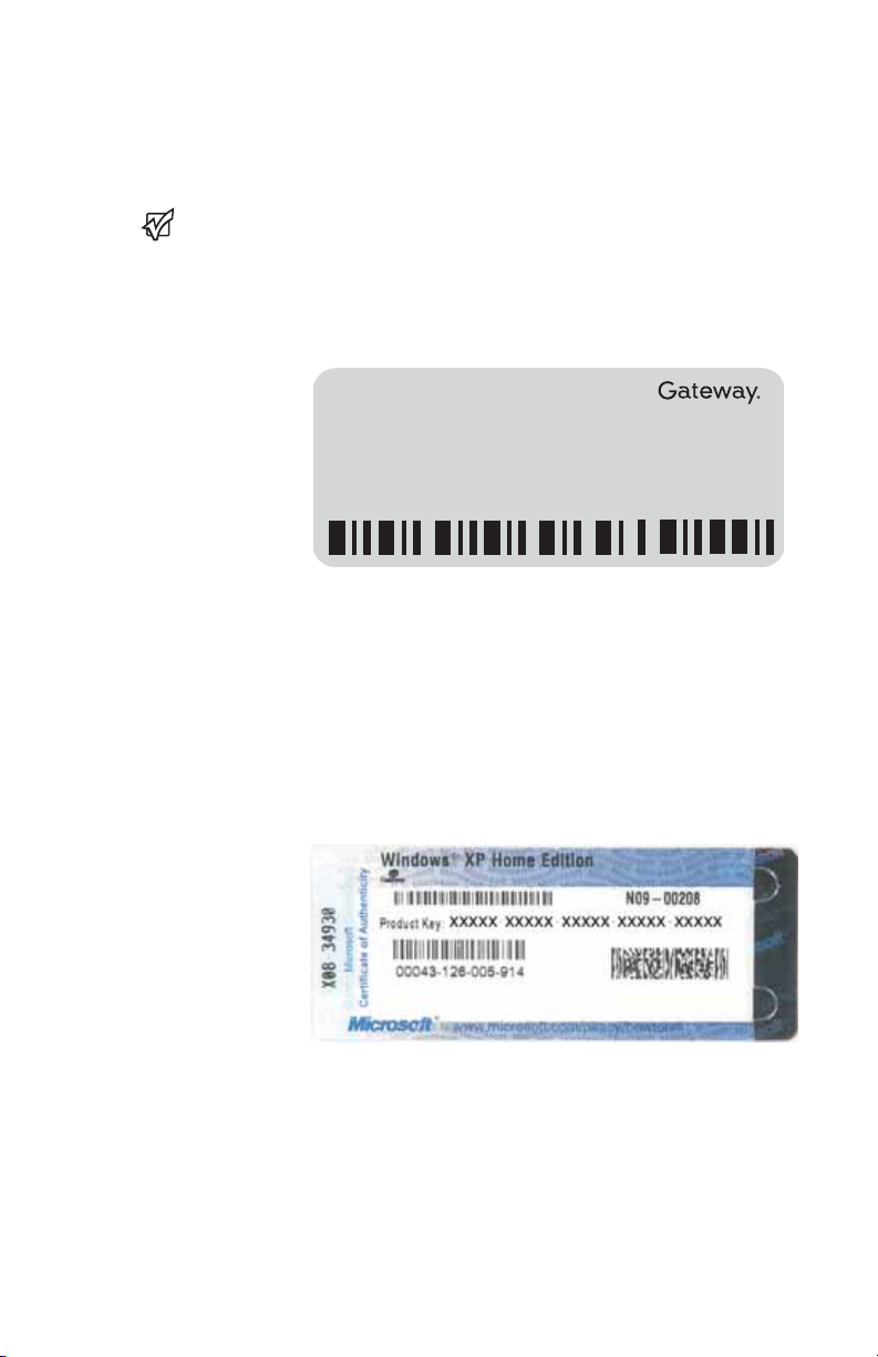
Gateway model and serial number
Important
The label shown in this
ordered, and location.
section is for
informational
purposes only. Label
information varies by
model, features
The label on the bottom of your notebook
contains information that identifies your
notebook model and its features. Gateway
Customer Care will need this information if you
call for assistance.
Online Support:
Tech Support Phone:
Hours:
Model:
S/No:
Microsoft Certificate of Authenticity
The Microsoft Certificate of Authenticity label
found on the bottom of your notebook includes
the product key code for your operating system.
3
Page 8

CHAPTER 1: About this reference
For more information
For more information about your notebook, visit
Gateway’s Support page at
support.gateway.com
shown on your notebook’s label. The Support
page also has links to additional Gateway
documentation and detailed specifications.
or the Web address
4
Page 9

CHAPTER 2
Checking Out Your Notebook
•Identifying features
• Starting your notebook
• Turning off your notebook
• Using the status indicators
•Using the keyboard
• Using the EZ Pad touchpad
• Turning your wireless radio on or off
• Using the DVD drive
• Using the memory card reader
• Adding and removing a PC Card
• Changing batteries
• Recalibrating the battery
• Ordering accessories
5
Page 10
CHAPTER 2: Checking Out Your Notebook
Identifying features
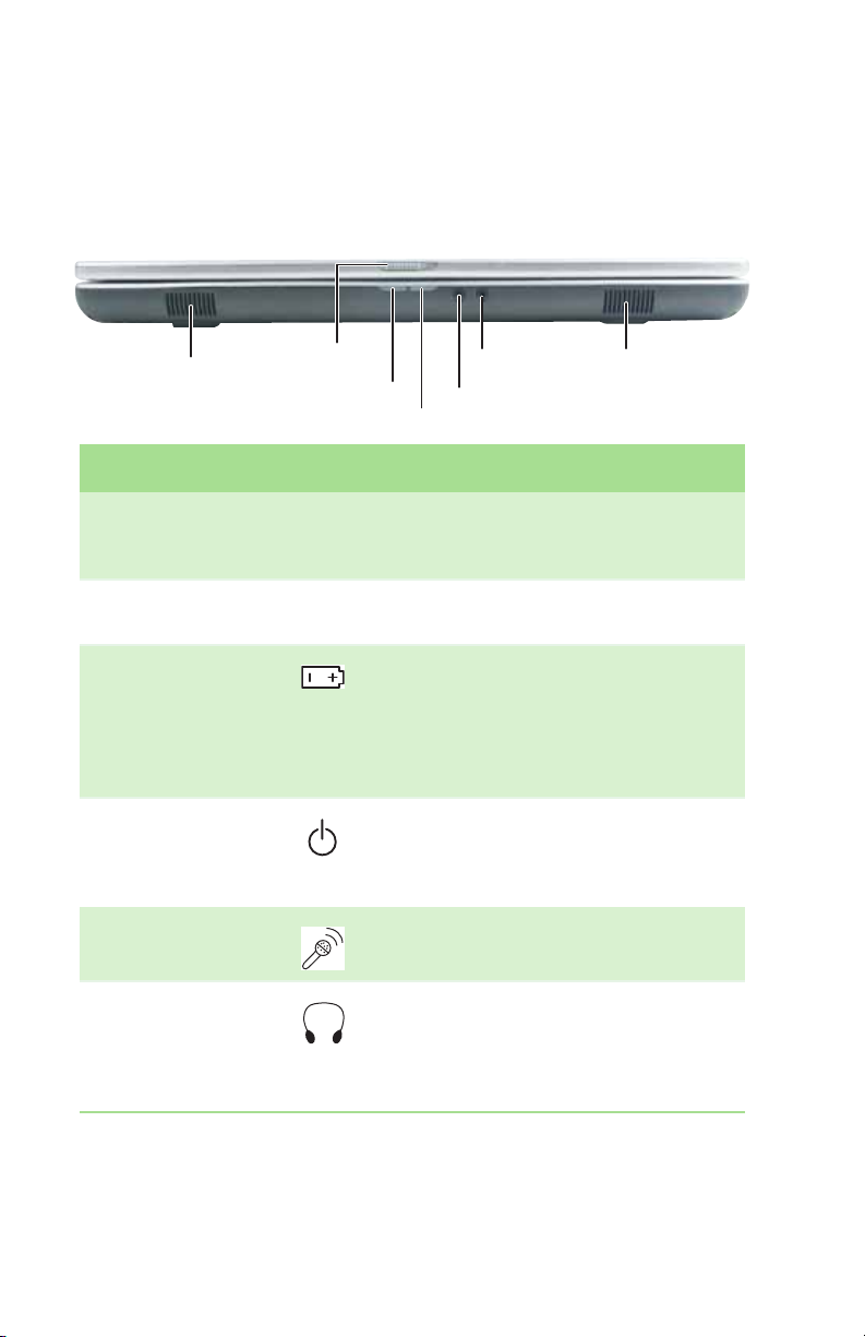
Front
Speaker
LCD panel release latch
Battery charge indicator
Headphone jack
Microphone jack
Speaker
Power indicator
Component Icon Description
Speakers Provide audio output when
LCD panel release
latch
Battery charge
indicator
Power indicator
Microphone jack Plug a microphone into this jack.
headphones or amplified speakers are
not plugged in.
Slide to open the LCD panel.
■
LED blue - battery is fully charged.
■
LED purple - battery is charging.
■
LED blinking red - battery charge is
very low.
■
LED solid red - battery is
malfunctioning.
■
LED on - notebook is on.
■
LED blinking - notebook is in
Standby mode.
■
LED off - notebook is off.
Headphone jack Plug amplified speakers or
headphones into this jack. The built-in
speakers are turned off when
speakers or headphones are plugged
into this jack.
6
Page 11
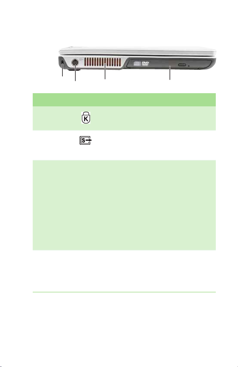
Left
Identifying features
Kensington lock slot
S-Video out jack
Ventilation fan
DVD drive
Component Icon Description
Kensington™
lock slot
S-Video out
jack (optional)
Ventilation fan Helps cool internal components.
Secure your notebook to an object by
connecting a Kensington cable lock to this
slot.
Plug an S-Video device, such as a television,
into this optional jack. For more information,
see Viewing the display on a television in the
User Guide.
War ning: Do not work for long periods with
your notebook resting on your lap. If the air
vents are blocked, your notebook may
become hot enough to harm your skin.
Caution: Do not block or insert objects into
these slots. If these slots are blocked, your
notebook may overheat resulting in
unexpected shutdown or permanent
damage to your notebook.
Caution: Provide adequate space around
your notebook so air vents are not
obstructed. Do not use your notebook on a
bed, sofa, rug, or other similar surface.
DVD drive Insert CDs or DVDs into this drive. For more
information, see “Using the DVD drive” on
page 29. To determine the type of drive in
your notebook, examine the drive tray’s
plastic cover and compare the logo to those
listed in “Identifying drive types” on page 29.
7
Page 12
CHAPTER 2: Checking Out Your Notebook
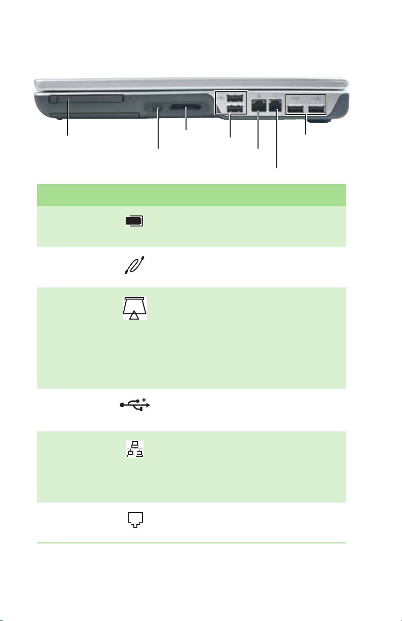
Right
PC Card slot
IEEE 1394 port
Memory card
reade r
USB ports
Ethernet jack
Modem jack
USB ports
Component Icon Description
PC Card slot Insert one Type II PC Card into this slot. For
IEEE 1394 port Plug an IEEE 1394 (also known as Firewire
Memory card
reader
USB ports Plug USB devices (such as a diskette drive,
more information, see “Adding and
removing a PC Card” on page 32.
®
or i.Link
camcorder) into this 4-pin IEEE 1394 port.
Insert a memory card from a digital camera,
MP3 player, PDA, or cellular telephone into
the memory card reader. For more
information, see “Using the memory card
reader” on page 30. The memory card
reader supports Memory Stick®, Memory
Stick Pro®, Mini Secure Digital®,
MultiMediaCard™, RS-MultiMediaCard™,
and Secure Digital™ cards.
flash drive, printer, scanner, camera,
keyboard, or mouse) into these ports.
) device (such as a digital
®
Ethernet jack Plug an Ethernet network cable into this
Modem jack Plug a modem cable into this jack. For more
jack. Plug the other end of the cable into a
cable modem, DSL modem, or Ethernet
network jack. For more information, see
“Connecting to a cable or DSL modem or to
an Ethernet network” on page 15.
information, see “Connecting the dial-up
modem” on page 14.
8
Page 13
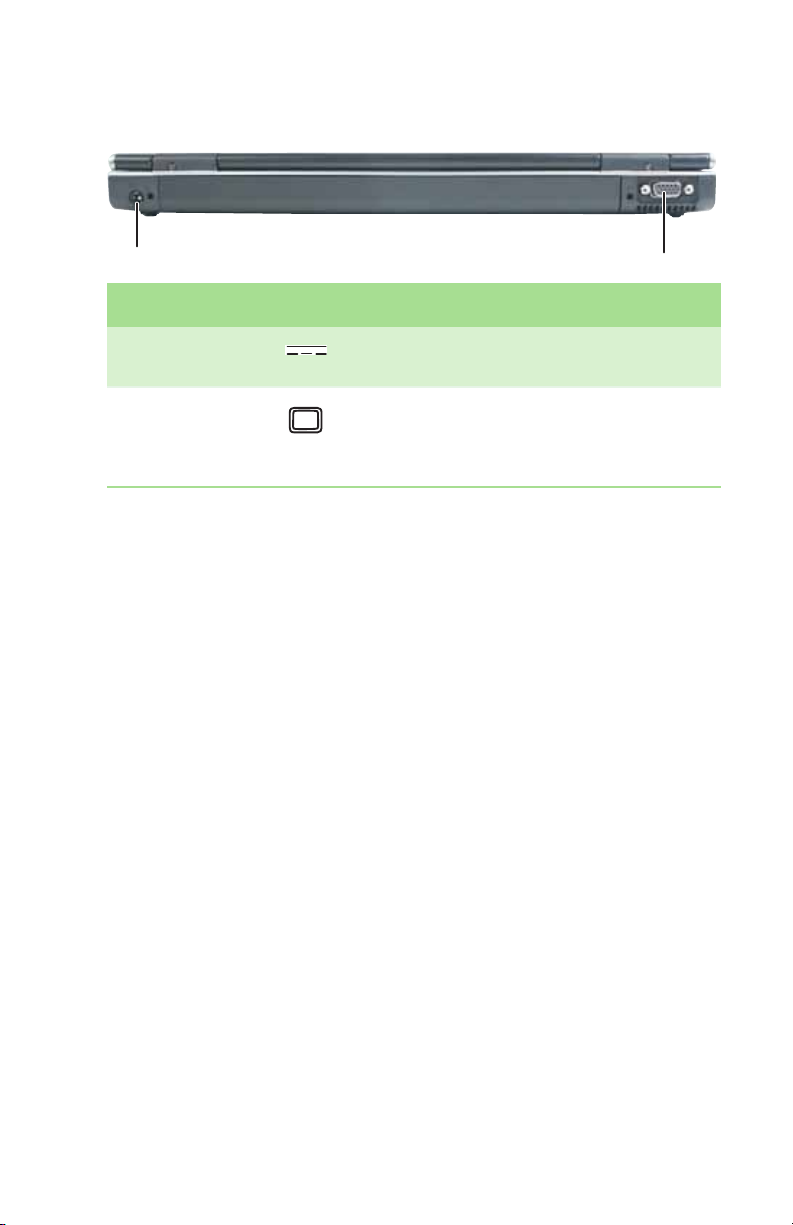
Back
Identifying features
Power connector
Monitor port
Component Icon Description
Power
connector
Monitor port Plug an analog VGA monitor or projector
Plug the AC adapter cable into this
connector.
into this port. For more information, see
“Viewing the display on a projector or
monitor” in the User Guide.
9
Page 14
CHAPTER 2: Checking Out Your Notebook
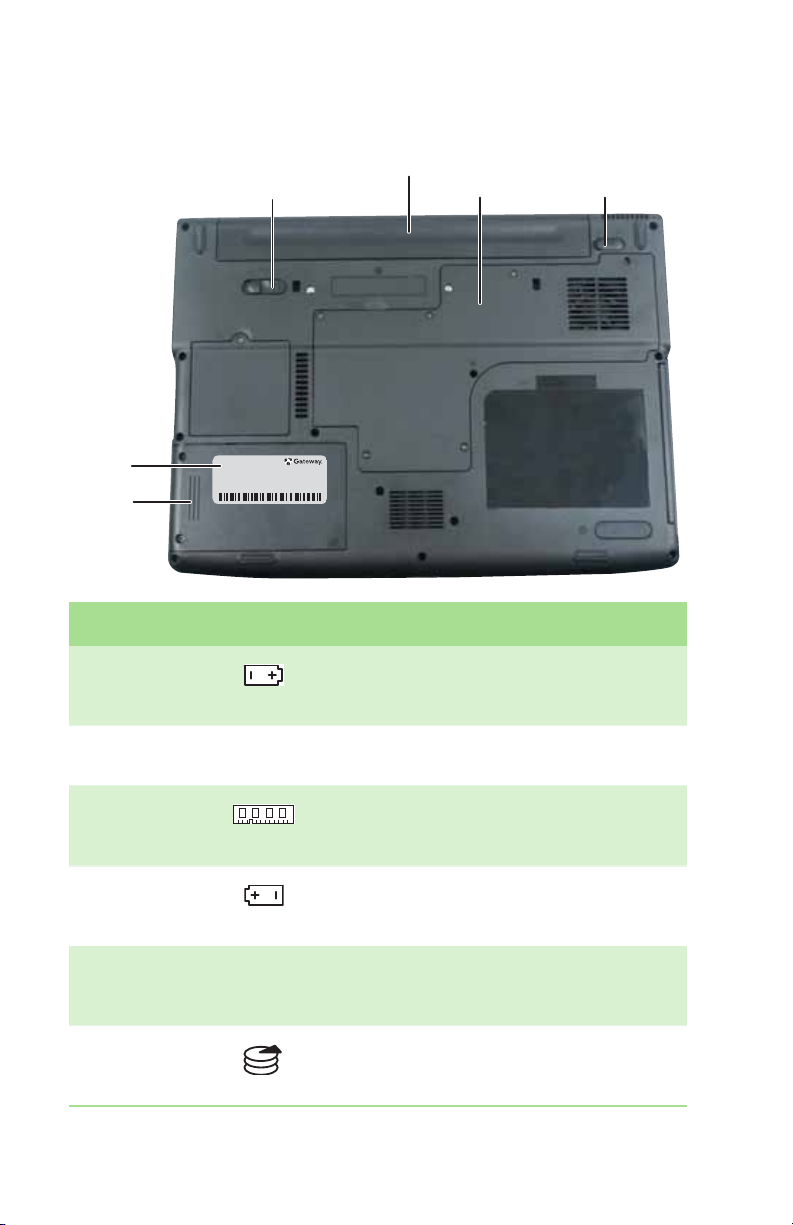
Bottom
System
label
Hard
drive
bay
Battery latch
Battery
Memory bay
Battery lock
Component Icon Description
Battery latch Slide to release the battery. For more
information, see “Changing batteries” on
page 33.
Battery Provides power when your notebook is not
Memory bay Install a memory module into this bay. For
Battery lock Slide to unlock the battery. For more
System label Includes the product model number. For
Hard drive bay The hard drive is located in this bay. For
plugged into AC power.
more information, see “Adding or
replacing memory” on page 39.
information, see “Changing batteries” on
page 33.
more information, see “Gateway model
and serial number” on page 3.
more information, see “Replacing the hard
drive kit” on page 45.
10
Page 15
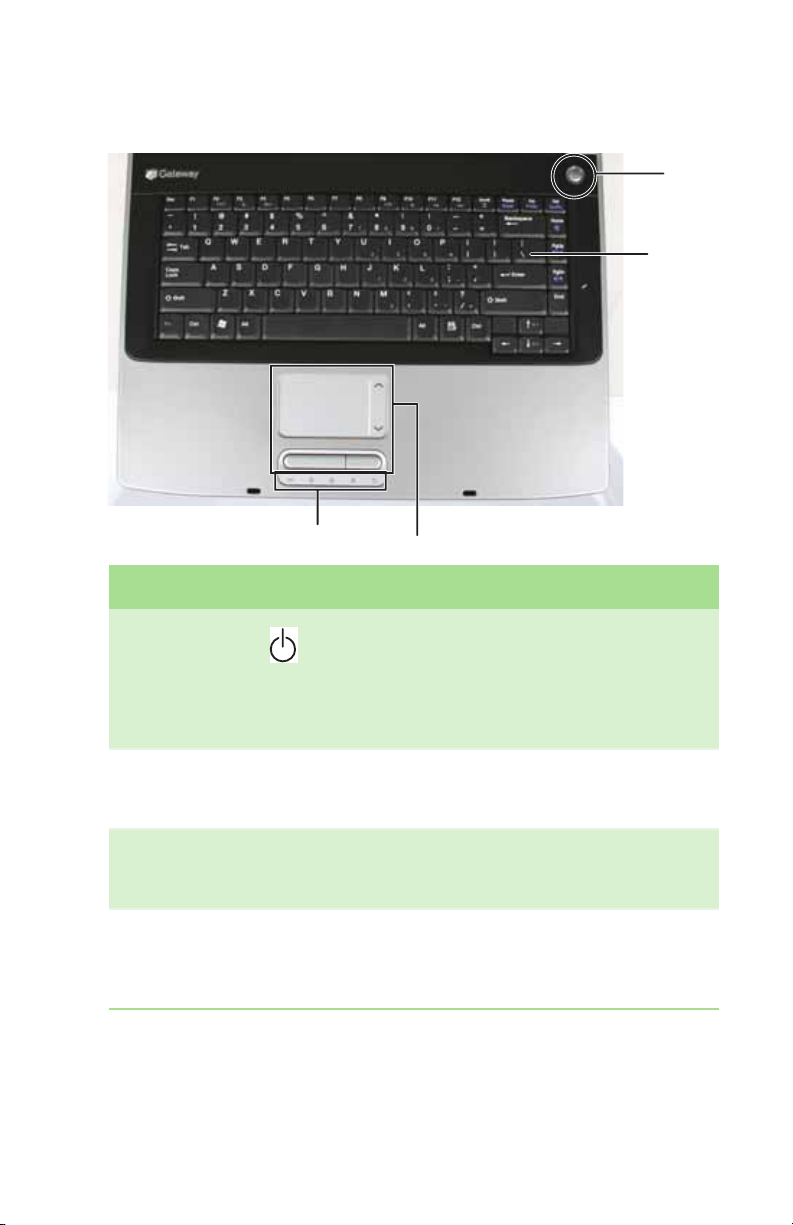
Keyboard area
Identifying features
Power
button
Keyboard
Status indicators
To uc h pa d
Component Icon Description
Power
button
Keyboard Provides all the features of a full-sized,
To uc hp ad Provides all the functionality of a mouse. For
Status
indicators
Press to turn the power on or off. You can also
configure the power button for
Standby/Resume mode. For more
information on configuring the power
button mode, see “Changing Power-Saving
Settings” in the User Guide.
computer keyboard. For more information,
see “Using the keyboard” on page 19.
more information, see “Using the EZ Pad
touchpad” on page 25.
Inform you when a drive is in use or when a
button has been pressed that affects how the
keyboard is used. For more information, see
“Using the status indicators” on page 18.
11
Page 16
CHAPTER 2: Checking Out Your Notebook
Connecting the AC adapter
Warnin g
Do not attempt to
disassemble the AC
adapter. The AC
adapter has no
user-replaceable or
user-serviceable parts
inside. The AC adapter
has dangerous
voltages that can
cause serious injury or
death. Contact
Gateway about
returning defective AC
Make sure that you use
the AC adapter that
notebook or one of the
same type purchased
must be of the same
rating as the original
cord or your notebook
adapters.
Caution
came with your
from Gateway.
Replace the power
cord if it becomes
damaged. The
replacement cord
type and voltage
may be damaged.
Important
If the battery charge
indicator does not turn
blue after three hours,
contact Gateway
Customer Care at
support.gateway.com
You can run your notebook using an AC adapter
or your notebook’s battery. The battery was
shipped to you partially charged. You should use
the AC adapter right away to fully charge the
battery. Allow three hours for the battery to fully
charge.
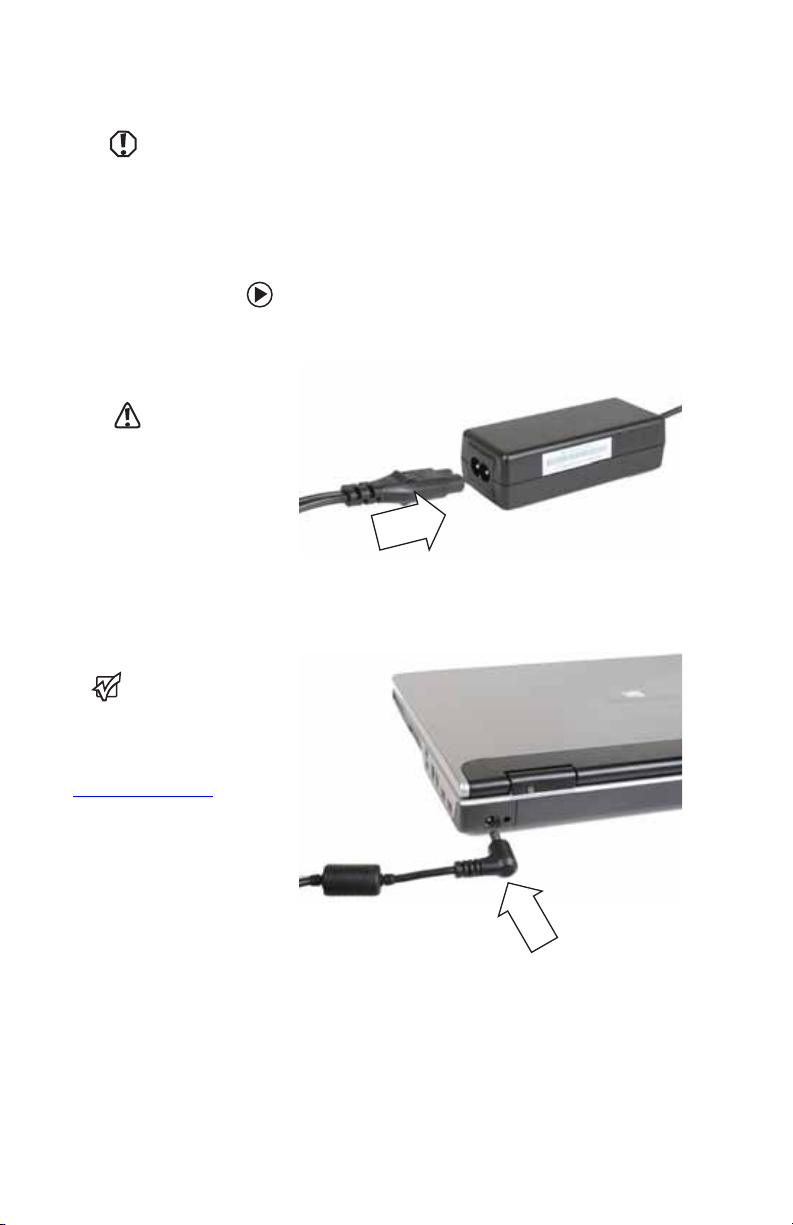
To connect the AC adapter:
1 Connect the power cord to the AC adapter.
2 Connect the AC adapter to your
notebook’s power connector.
.
12
Page 17
Connecting the AC adapter
Important
If the battery is not
fully charged before
you use your notebook
on battery power for
the first time, the
battery life may be
much shorter than you
expect. If the battery
life seems short even
after being charged for
three hours, the
battery may nee d to be
recalibrated. For
information on
recalibrating the
battery, see
“Recalibrating the
battery” on page 35
3 Plug the power cord into a wall outlet. The
battery charge indicator turns on (see
“Front” on page 6 for the location of the
battery charge indicator). If the battery
charge indicator does not turn on,
complete the following steps until it turns
on:
1 Unplug the adapter from your
notebook, then plug it back in.
2 Press FN+F1 to toggle the status
lights on and off.
4 When you finish using your notebook for
the first time, turn off your notebook and
leave your notebook connected to
AC power until the battery charge
indicator turns blue.
Protecting from power source problems
Warnin g
High voltages can
enter your notebook
through both the
power cord and the
modem connection.
To protec t y our
notebook and avoid
electrical shock, use a
surge protector. If you
have a telephone
modem, use a surge
protector that has a
modem jack. If you
have a cable modem,
use a surge protector
unplug both the surge
that has an
antenna/cable TV
jack. During an
electrical storm,
protector and the
modem.
During a power surge, the voltage level of
electricity coming into your notebook can
increase to levels far above normal levels and
cause data loss or system damage. Protect your
notebook and peripheral devices by connecting
them to a surge protector, which absorbs voltage
surges and prevents them from reaching your
notebook.
13
Page 18
CHAPTER 2: Checking Out Your Notebook
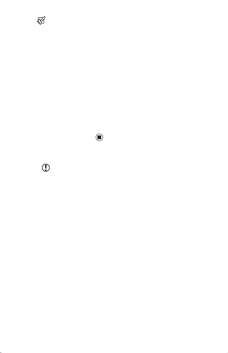
Connecting the dial-up modem
Warnin g
To re du ce the risk of
fire, use only No. 26
AWG or larger
telecommunications
line cord.
Your notebook has a built-in 56K modem that
you can use to connect to a standard telephone
line.
To connect the modem:
1 Insert one end of the modem cable into the
modem jack on the right side of your
notebook.
2 Insert the other end of the modem cable
into a telephone wall jack. The modem will
not work with digital or PBX telephone
lines.
14
3 Start your notebook, then start your
communications program.
Page 19
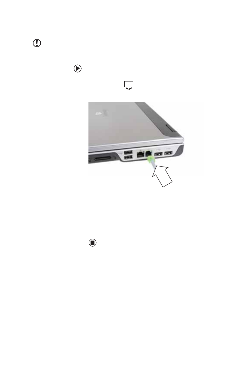
Connecting to a cable or DSL modem or to an Ethernet network
Connecting to a cable or DSL
modem or to an Ethernet network
Your notebook has a network jack that you can
use to connect to a cable or DSL modem or to
an Ethernet network.
To connect to a cable or DSL modem or to an
Ethernet network:
1 Insert one end of the network cable into
the network jack on the right side of
your notebook.
2 Insert the other end of the network cable
into a cable modem, DSL modem, or
Ethernet network jack.
15
Page 20

CHAPTER 2: Checking Out Your Notebook
Starting your notebook
Warnin g
Do not work for long
periods with your
notebook resting on
your lap. If the air vents
are blocked, your
notebook may
become hot enough to
harm your skin.
Caution
Provide adequate
space around your
notebook so air vents
are not obstructed. Do
not use your notebook
on a bed, sofa, rug, or
other similar surface.
To start your notebook:
1 Slide the latch on the front of your
notebook, then lift the LCD panel.
2 Press the power button located above the
keyboard.
Tips & Tricks
For more information
about changing the
power button mode,
see “Changing
Power -Savin g
Settings” in the User
Guide.
3 If you are starting your notebook for the
first time, follow the on-screen instructions
to set up your notebook.
Waking up your notebook
Tips & Tricks
For more information
about Standby mode,
see “Changing power
modes” in the User
Guide.
When you have not used your notebook for
several minutes or if you close the LCD panel
without turning off your notebook, it may enter
a power-saving mode called Standby. While in
Standby, the power indicator flashes. If your
notebook is in Standby mode, press the power
button to “wake” it up.
T urning off your notebook
Important
If for some reason you
cannot use the Turn
Off Computer option
in Windows to turn off
your notebook, press
and hold the power
button for about five
seconds, then release
16
it.
To turn off your notebook:
1 Click Start, then click Turn Off Computer.
The Turn Off Computer dialog box opens.
2 Click Turn O ff. Windows shuts down and
turns off your notebook.
Page 21

Restarting (rebooting) your notebook
Restarting (rebooting) your
notebook
Important
If your notebook does
battery for more than
not turn off
immediately,
complete the
following
steps until your
notebook turns off:
1. Press and hold the
power button for
about five seconds,
then release it.
2. Unplug the power
cord and remove the
10 seconds.
If your notebook does not respond to keyboard,
touchpad, or mouse input, you may have to
close programs that are not responding. If
closing unresponsive programs does not restore
your notebook to normal operation, you may
have to restart (reboot) your notebook.
To close unresponsive programs and restart
your notebook:
1 Press CTRL+ALT+DEL. The Windows Security
dialog box opens.
2 Click Task Man ager. The Windows Task
Manager dialog box opens.
3 Click the program that is not responding.
4 Click End Task.
5 Click X in the top-right corner of the
Windows Task Manager dialog box.
6 If your notebook does not respond, turn it
off, wait ten seconds, then turn it on again.
As a part of the regular startup process, a
program to check the disk status runs
automatically. When the checks are
finished, Windows starts.
17
Page 22
CHAPTER 2: Checking Out Your Notebook
A
1
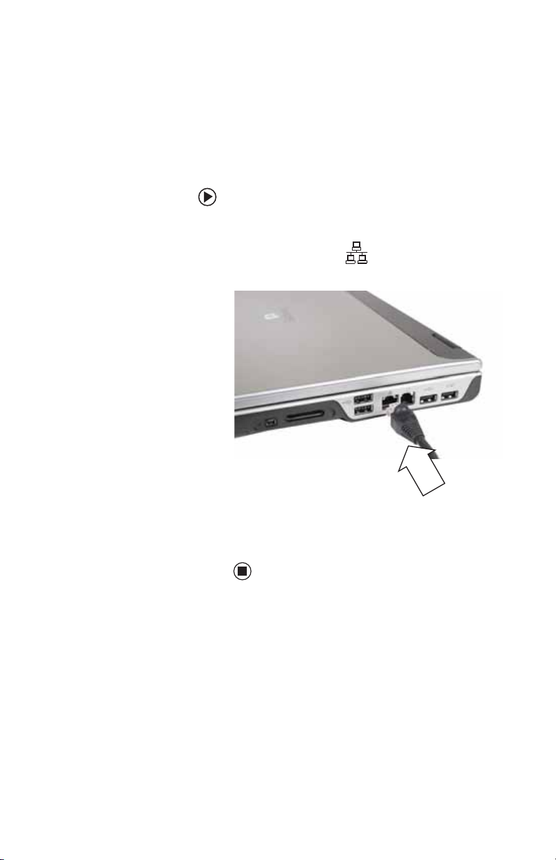
Using the status indicators
Important
If none of the
indicators are on, you
may need to press
N+F1 to toggle the
F
status indicators on.
Status indicators inform you when a drive is
being used or when a button has been pressed
that affects how the keyboard is used. The status
indicators are located below the touchpad.
Wireless network
Caps lock
Num lock
Hard drive
Disc drive
Indicator Icon Description
Wireless
network
(optional)
■
LED on - Wireless radio is
turned on.
■
LED off - Wireless radio is
turned off.
■
Caps lock
LED on - Caps lock is
turned on.
■
LED off - Caps lock is
turned off.
Num lock
■
LED on - Numeric keypad
is turned on.
■
LED off - Numeric keypad
is turned off.
18
Page 23
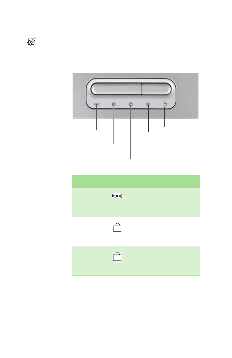
Indicator Icon Description
Using the keyboard
Disc drive
Hard drive
Using the keyboard
Tips & Tricks
You can attach an
external keyboard to
your notebook using a
USB port. You do not
need to shut down
your notebook to
connect a USB
keyboard.
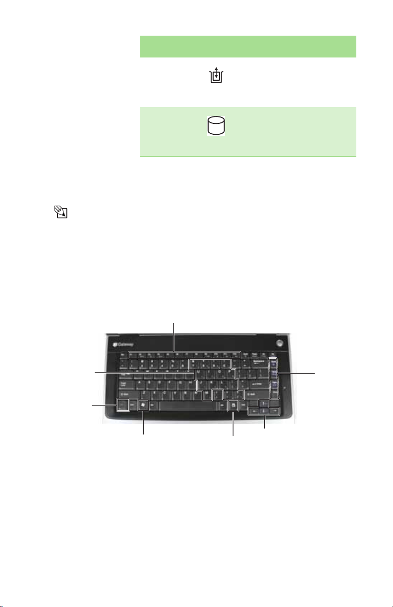
Your notebook features a full-size keyboard that
functions the same as a desktop computer
keyboard. Many of the keys have been assigned
alternate functions, including shortcut keys for
Windows, function keys for specific system
operations, and the Num Lock keys for the
numeric keypad.
Function keys/ System keys
■
LED blinking - The disc
drive is in use.
■
LED off - The disc drive is
not in use.
■
LED blinking - The hard
drive is in use.
■
LED off - The hard drive is
not in use.
Numeric
keypa d
N key
F
Windows key
Application key
Navigation
keys
Arrow keys
19
Page 24

CHAPTER 2: Checking Out Your Notebook
Key types
The keyboard has several different types of keys.
Some keys perform specific actions when
pressed alone and other actions when pressed in
combination with another key.
Key type Icon Description
Function
keys
System keys Press these colored keys
Navigation
keys
Press these keys labeled
F1 to F12 to perform
actions in programs. For
example, pressing F1 may
open help.
Each program uses
different function keys for
different purposes. See
the program
documentation to find
out more about the
function key actions.
in combination with the
N key to perform specific
F
actions. For more
information, see “System
key combinations” on
page 22.
Press these keys to move
the cursor to the
beginning of a line, to the
end of a line, up the page,
down the page, to the
beginning of a document,
or to the end of a
document.
20
Arrow keys Press these keys to move
the cursor up, down, right,
or left.
Application
key
Press this key for quick
access to shortcut menus
and help assistants in
Windows.
Page 25

Using the keyboard
1
Key type Icon Description
Windows
key
FN key Press the FN key in
Numeric
keypad
Press this key to open the
Windows Start menu.
This key can also be used
in combination with other
keys to open utilities like
F (Search utility), R (Run
utility), and E (Explorer
utility).
combination with a
colored system key to
perform a specific action.
Use these keys to type
numbers when the
numeric keypad is turned
on. Press F
on the numeric keypad.
N+ to turn
21
Page 26
CHAPTER 2: Checking Out Your Notebook
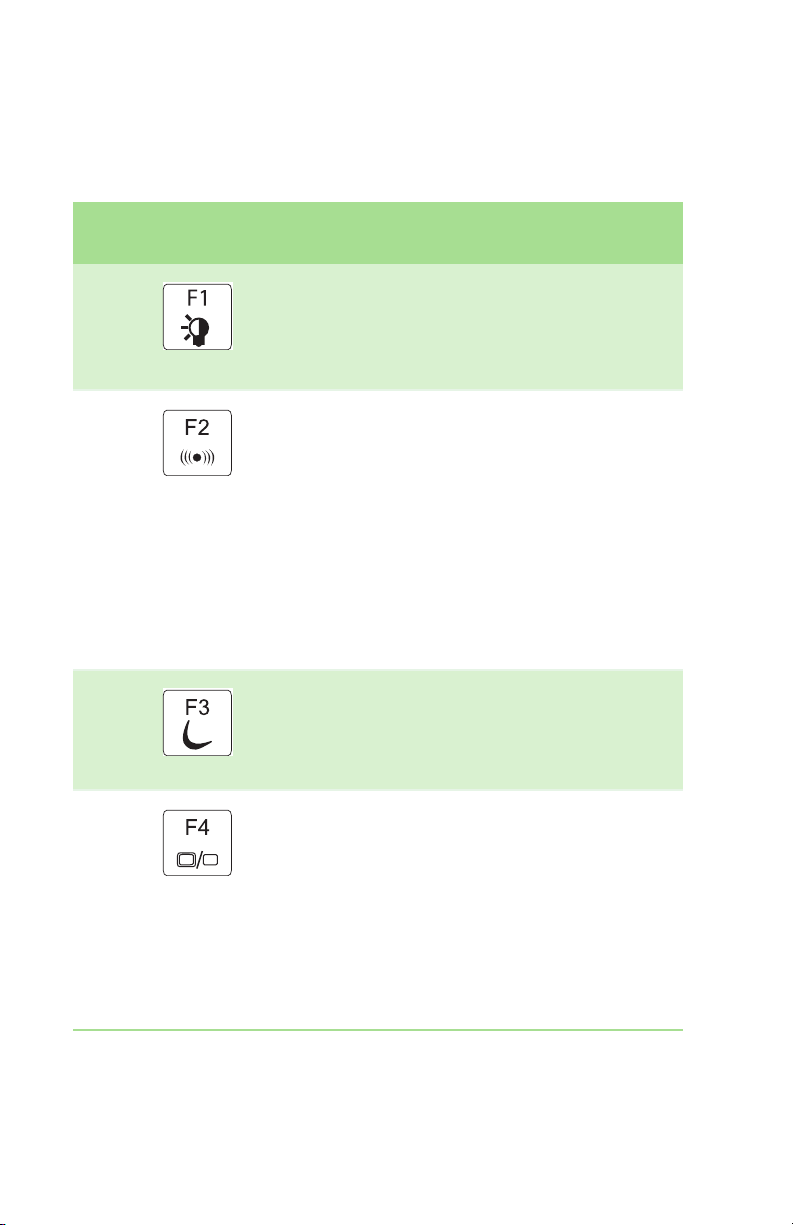
System ke y combinat ions
When you press the FN key and a system key at
the same time, your notebook performs the
action identified by the text or icon on the key.
Press and hold FN, then
press this system key...
To. ..
Toggle the status indicators on or off. For
more information, see “Using the status
indicators” on page 18.
Turn the optional wireless network on or
off. For more information, see “Wireless
Networking” in your User Guide.
War ning: Radio frequency wireless
communication can interfere with
equipment on commercial aircraft.
Current aviation regulations require
wireless devices to be turned off while
traveling in an airplane. IEEE 802.11g,
IEEE 802.11b, and IEEE 802.11a
communication devices are examples of
devices that provide wireless
communication.
Enter Standby mode. Press the power
button to leave Standby mode. For more
information, see “Changing
Power-Saving Settings” in your User
Guide.
22
Toggle your notebook display in the
following order:
■
The LCD
■
An external monitor or projector (a
monitor or projector must be plugged
into the monitor port on your
notebook)
■
Both displays at the same time
For more information, see Viewing the
display on a projector or monitor in the
User Guide.
Page 27

Using the keyboard
Press and hold FN, then
press this system key...
6
F8
+
-
To. ..
Display the power status box in the
upper-left corner of your display. The box
shows the battery charge level, the BIOS
version, and whether the optional
wireless network is being used. Press the
key combination again to close this box.
Turn the optional Bluetooth feature on or
off.
War ning: Radio frequency wireless
communication can interfere with
equipment on commercial aircraft.
Current aviation regulations require
wireless devices to be turned off while
traveling in an airplane. Bluetooth
communication devices are examples of
devices that provide wireless
communication.
Increase the LCD panel brightness above
the normal brightest setting. Use this
feature in bright lighting situations, such
as outside in bright sunlight.
Press a second time to decrease the
brightness below the normal lowest
brightness setting. Use this feature in
dim lighting situations.
Press a third time to return the display to
the normal brightness setting.
Important: Using this feature will affect
battery performance.
Play or pause the CD or DVD.
Stop playing the CD or DVD.
Skip back one CD song or DVD track.
23
Page 28

CHAPTER 2: Checking Out Your Notebook
Press and hold FN, then
press this system key...
To. ..
Skip ahead one CD song or DVD track.
Increase the brightness of the display.
Decrease the brightness of the display.
Mute the sound. Press the key
combination again to restore the sound.
For more information, see “Adj usti ng the
volume” on page 27.
Increase the volume. For more
information, see “Adjusting the volume”
on page 27.
Decrease the volume. For more
information, see “Adjusting the volume”
on page 27.
24
Page 29

Using the EZ Pad touchpad
Using the EZ Pad touchpad
Tips & Tricks
For instructions on
how to adjust the
double-click speed,
pointer speed,
right-hand or
configuration, and
“Changing the mouse
or touchpad settings”
left-hand
other touchpad
settings, see
in the User Guide.
Tips & Tricks
You received your
notebook with the EZ
Pad touchpad set to
only accept clicking by
using the touchpad
buttons. You can
change this feature to
allow tapping on the
touchpad to simulate
clicking the left button.
For more information,
see “Changing the
mouse or touchpad
settings” in the User
Guide.
The EZ Pad™ consists of a touchpad, two
buttons, and a scroll zone.
Tou ch pa d
Scroll
zone
Left button
Right button
When you move your finger on the touchpad,
the pointer (arrow) on the screen moves in the
same direction. You can use the scroll zone to
scroll through documents. Use of the scroll zone
may vary from program to program.
You can use the EZ-Pad left and right buttons
below the touchpad to select objects.
25
Page 30

CHAPTER 2: Checking Out Your Notebook
To. .. Do this...
Move the
pointer on the
screen.
Select an
object on the
screen.
Start a
program or
open a file or
folder.
Move your finger
around on the
touchpad. If you
run out of space
and need to move
the pointer
farther, lift your
finger, move it to
the middle of the
touchpad, then
continue moving
your finger.
Position the
pointer over the
object. Quickly
press and release
the left button
once. This action
is called clicking.
Position the
pointer over the
object. Press the
left button twice
in rapid
succession. This
action is called
double-clicking.
Access a
shortcut
menu or find
more
information
about an
object on the
screen.
26
Position the
pointer over the
object. Quickly
press and release
the right button
once. This action
is called
right-clicking.
Page 31

To. .. Do this...
Adjusting the volume
Move an
object on the
screen.
Adjusting the volume
Tips & Tricks
For instructions on
how to adjust the
volume in Windows,
see “Adjusting the
Volume” in the User
Guide.
You can use the volume control to adjust the
overall volume of your notebook.
To adjust the overall volume level using
hardware controls:
■ If you are using external speakers, turn the
knob on the front of the speakers.
Position the
pointer over the
object. Press the
left button and
hold it down,
then use the
touchpad to
move (drag) the
object to the
appropriate part
of the screen.
Release the
button to drop
the object where
you want it.
-OR-
Use the mute and volume control buttons
on the keyboard. For more information, see
“System key combinations” on page 22.
27
Page 32

CHAPTER 2: Checking Out Your Notebook
T urning your wireless radio on or off
Warnin g
Radio frequency
communication can
commercial aircraft.
regulations require
wireless devices to be
airplane. IEEE 802.11a,
IEEE 802.11g, and
devices are examples
of devices that provide
wireless
interfere with
equipment on
Current aviation
turned off while
traveling in an
IEEE 802.11b,
Bluetooth
communication
wireless
communication.
Warnin g
In environments
where the risk of
interference to other
devices or services is
harmful or perceived
as harmful, the option
to use a wireless device
may be restricted or
eliminated. Airports,
hospitals, and oxygen
or flammable gas
laden atmospheres
are limited examples
where use of wireless
devices may be
restricted or
eliminated. When in
environments where
you are uncertain of
the sanction to use
wireless devices, ask
the applicable
authority for
authorization prior to
using or turning on th e
wireless device.
Tips & Tricks
For more information
about using your
notebook on a wireless
network, see “Wireless
Networking” in the
User Guide.
Your Gateway notebook may have a
factory-installed wireless networking mini-PCI
card.
To turn the wireless IEEE 802.11 radio on or off:
■ Press FN + F2. The wireless status indicator
turns on or off. For the location of the
wireless status indicator, see “Using the
status indicators” on page 18.
To turn the Bluetooth radio on or off:
■ Press FN + F6.
28
Page 33

Using the DVD drive
You can use your notebook to enjoy a wide
variety of multimedia features.
Identifying drive types
Using the DVD drive
Important
To use the double layer
capability of a double
layer recordable DVD
drive, the blank DVDs
you purchase must
state Double Layer,
Dual Layer, or DL.
Using other types of
blank media will result
in less capacity.
If your drive has
this logo...
Your Gateway notebook may contain one of the
following drive types. Look on the front of the
drive for one or more of the following logos:
This is your drive
Use your drive for...
type...
ROM/R/RW
DVD drive Installing programs,
Combination
DVD/CD-RW
drive
Multi-format
double layer
DVD±RW/CD-R
W drive
playing audio CDs,
playing DVDs, and
accessing data. You
cannot use this drive to
create CDs or DVDs.
Installing programs,
playing audio CDs,
playing DVDs, accessing
data, and recording
music and data to
recordable CDs. You
cannot use this drive to
create DVDs.
Installing programs,
playing audio CDs,
playing DVDs, accessing
data, recording music
and data to CD-R or
CD-RW discs, and
recording video and data
to DVD-R, DVD+R,
DVD-RW, DVD+RW, or
double layer DVD+R
discs.
29
Page 34

CHAPTER 2: Checking Out Your Notebook
Inserting a CD or DVD
[
To insert a CD or DVD:
1 Press the eject button on the DVD drive.
After the tray opens slightly, pull the disc
tray completely open.
Important
When you place a
single-sided disc in the
tray, make sure that
the label side is facing
up. If the disc has two
playable sides, place
the disc so the name of
the side you want to
play is facing up.
2 Place the disc in the tray with the label
facing up, then press down carefully on the
disc until it snaps into place.
3 Push the tray in until it is closed.
Eject button
Manual eject hole
Using the memory card reader
You can use memory cards to transfer pictures
from a digital camera to your notebook. You can
also use the memory card reader to transfer data
between your notebook and a device that uses
memory cards, such as a PDA, MP3 player, or
cellular telephone.
Memory card types
The memory card reader supports Memory
Stick®, Memory Stick Pro®, Mini Secure Digital®,
MultiMediaCard™, RS-MultiMediaCard™, and
Secure Digital™ cards.
30
Page 35

Inserting a memory card
To insert a memory card:
■ Insert the memory card into the memory
card slot with the label facing up and the
arrow on the label pointing towards your
notebook.
Using a memory card
To access a file on a memory card:
1 Click Start, then click My Computer.
2 Double-click the drive letter (for example,
the E: drive), then double-click the file
name.
Removing a memory card
Using the memory card reader
Important
Do not use the remove
hardware icon in
the taskbar to remove
the memory card. If
you use the remove
hardware icon, your
notebook may not
recognize your
memory card reader
until you restart your
notebook.
To remove a memory card:
1 Push the memory card into your notebook.
The memory card pops out slightly.
2 Pull the memory card out of your
notebook.
31
Page 36

CHAPTER 2: Checking Out Your Notebook
Adding and removing a PC Card
Your notebook has a PC Card slot (also known as
a PCMCIA card slot). This slot accepts one Type II
card. You do not need to restart your notebook
when changing most cards because your
notebook supports hot-swapping.
Hot-swapping means that you can insert a
PC Card while your notebook is running. If your
PC Card does not work after hot-swapping, see
the PC Card manufacturer’s documentation for
further information.
To insert a PC Card:
■ Push the card firmly into the PC Card slot,
label-side up, until the outer edge of the
card is flush with the side of your
notebook.
Important
If the remove
hardware icon does
not appear on the
taskbar, click the show
icons button.
hidden
32
To remove a PC Card:
1 Click the remove hardware icon in the
taskbar, the PC Card name, then click Stop.
-OR-
Turn off your notebook.
2 Release the eject button by pressing the
PC Card eject button once.
Page 37

3 Eject the PC Card by pressing the eject
button again.
Changing batteries
Changing batteries
Danger of explosion if
manufactured for your
Discard used batteries
The battery used in this
device may present a
hazard if mishandled.
(100°C), or incinerate.
battery promptly. Keep
Warnin g
battery is incorrectly
Replace only with a
battery specifically
Gateway notebook.
hazardous material
fire or chemical burn
Do not disassemble,
away from children.
replaced.
according to local
regulations.
heat above 212°F
Dispose of used
If your notebook is connected to AC power, you
can change the battery while your notebook is
turned on. If your notebook is not plugged into
an AC outlet, you must turn your notebook off
while changing the battery.
To change the battery:
1 If your notebook is on and is connected to
AC power, go to Step 2.
-OR-
If your notebook is on and is not plugged
into an AC outlet, save your work and turn
off your notebook.
2 Close the LCD panel.
3 Turn your notebook over so the bottom is
facing up.
33
Page 38

CHAPTER 2: Checking Out Your Notebook
4 Slide the battery lock to the unlocked
position.
5 Slide the battery release latch, then slide
the battery out of your notebook.
34
6 Slide a recharged battery into your
notebook until it snaps into place.
7 Slide the battery lock to the locked
position.
8 Turn your notebook over.
9 Open the LCD panel.
Page 39

Recalibrating the battery
Recalibrating the battery
Important
Do not interrupt the
battery recalibration
interrupted, you must
start the process over
process. If
recalibration is
again.
If your notebook unexpectedly goes into
Standby mode while you are using it but the
battery charge is not low, you may need to
recalibrate your battery. You should also
recalibrate the battery periodically to maintain
the accuracy of the battery gauge.
To recalibrate the battery:
1 Connect the AC adapter, then turn on your
notebook.
2 As soon as it starts and you see a startup
screen, press F2. The BIOS Setup utility
opens.
3 Open the Advanced menu.
4 Highlight Battery Auto Learning, then
select Enabled by pressing the spacebar.
5 Open the Exit menu, then highlight Exit
Saving Changes and press E
6 Select Ye s , then press ENTER.
The battery recalibration process begins
and a screen opens showing you the
progress. The entire process will take
several hours.
NTER.
When the recalibration has finished, the
message “Press [Esc] key to exit” appears.
7 Press ESC. The battery charge indicator
now displays an accurate battery charge. If
the battery charge indicator does not show
an accurate charge, contact Gateway
Customer Care at support.gateway.com
.
35
Page 40

CHAPTER 2: Checking Out Your Notebook
Ordering accessories
To order accessories, visit the Accessory Store at
accessories.gateway.com
Batteries
If you run your notebook on battery power for
extended periods, you may want to buy an
additional battery so you can swap batteries
when necessary. See “Changing batteries” on
page 33 for more information about using an
additional battery.
Carrying cases
Gateway has large-capacity carrying cases if you
need additional space for accessories or
supplies.
Memory
Large programs, such as multimedia games or
graphics programs, use a lot of memory. If your
programs are running more slowly than you
think they should, try adding more memory. See
“Adding or replacing memory” on page 39 for
more information.
.
36
Printers
You can attach almost any type of printer to your
notebook. The most common types are inkjet
and laser printers, which print in color or black
and white.
Inkjet printers and cartridges are relatively
inexpensive, but they are slower than laser
printers. Using an inkjet color printer, you can
print pictures, banners, and greeting cards, as
well as documents.
Laser printers and cartridges are more
expensive, but they print much faster than inkjet
printers. Laser printers are better than inkjet
printers when you are printing large documents.
USB flash drive
Use a USB flash drive for storing files or
transferring files to another computer.
Page 41

CHAPTER 3
Upgrading Your Notebook
• Preventing static electricity discharge
• Adding or replacing memory
• Replacing the DVD drive
• Replacing the hard drive kit
• Replacing the keyboard
37
Page 42

CHAPTER 3: Upgrading Your Notebook
Preventing static electricity discharge
Warnin g
To avoid exposure to
dangerous electrical
voltages and moving
parts, turn off your
notebook and unplug
the power cord,
modem cable, and
network cable before
opening the case.
Warnin g
To prevent risk of
electric shock, do not
insert any object into
the vent holes of your
notebook.
Important
Before installing or
information in this
replacing
components, you
should read and
understand the
section .
The components inside your notebook are
extremely sensitive to static electricity, also
known as electrostatic discharge (ESD).
Before installing or replacing components,
follow these guidelines:
■ Avoid static-causing surfaces such as
carpeted floors, plastic, and packing foam.
■ Remove components from their antistatic
bags only when you are ready to use them.
Do not lay components on the outside of
antistatic bags because only the inside of
the bags provide electrostatic protection.
■ Always hold components by their edges.
Avoid touching the edge connectors.
Never slide components over any surface.
■ Wear a grounding wrist strap (available at
most electronics stores) and attach it to a
bare metal part of your workbench or other
grounded connection.
■ Touch a bare metal surface on your
workbench or other grounded object.
38
Page 43

Adding or replacing memory
Adding or replacing memory
Important
Use only memory
modules designed for
your Gateway
notebook.
To ol s
Required
You need a small
Phillips screwdriver to
add or replace a
memory module.
Your notebook uses memory modules called
SO-DIMMs (Small Outline Dual Inline Memory
Modules). The modules are available in various
capacities and any module can be placed in any
slot.
Memory bay
To add or replace memory modules:
1 Follow the guidelines under “Preventing
static electricity discharge” on page 38.
2 Turn off your notebook.
3 Disconnect the AC adapter, modem cable,
and network cable.
4 Disconnect all peripheral devices and
remove any PC cards.
5 Turn your notebook over so the bottom is
facing up, then remove the battery. For
more information, see “Changing
batteries” on page 33.
39
Page 44

CHAPTER 3: Upgrading Your Notebook
Tips & Tricks
The keyboard screw
hole is marked with a
K. Depending on your
model, not all screws
may be captive.
6 Remove the keyboard screw shown in the
following picture, then loosen the
remaining six captive screws (these screws
cannot be removed).
Screw
Screw
Screw
Screw
Keyboard
screw
Screw
7 Use the thumb notch to lift the memory
Screw
bay cover, then remove it. Be careful not to
break off the tabs located on the end of the
cover opposite of the thumb notch.
40
Page 45

Adding or replacing memory
8 If you are removing a module, gently press
outward on the clip at each end of the
memory module until the module tilts
upward.
9 Pull the memory module out of the slot.
41
Page 46

CHAPTER 3: Upgrading Your Notebook
Important
Use only memory
modules designed for
your Gateway
notebook.
10 Hold the new or replacement module at a
30-degree angle and slide it into the empty
memory slot. This module is keyed so it can
only be inserted in one direction. If the
module does not fit, make sure that the
notch in the module lines up with the tab
in the memory bay.
11 Gently push the module down until it clicks
in place.
12 Replace the memory bay cover, then
tighten the captive screws.
13 Replace the keyboard screw.
14 Insert the battery, then turn your notebook
over.
15 Connect the power adapter, modem cable,
and network cable, then turn on your
notebook.
Replacing the DVD drive
Important
Replace the DVD drive
only with a similar
drive provided by
Gateway.
To ol s
Required
You need a small
Phillips screwdriver to
replace the DVD drive.
42
If your DVD drive becomes damaged, you can
replace it with a similar drive obtained from
Gateway.
To replace the DVD drive:
1 Make sure that the DVD drive is empty.
2 Follow the guidelines under “Preventing
static electricity discharge” on page 38.
3 Turn off your notebook.
4 Disconnect the AC adapter, modem cable,
and network cable.
5 Disconnect all peripheral devices and
remove any PC Cards.
6 Turn your notebook over so the bottom is
facing up, then remove the battery. For
more information, see “Changing
batteries” on page 33.
Page 47

Tips & Tricks
The keyboard screw
hole is marked with a
K. Depending on your
model, not all screws
may be captive.
Replacing the DVD drive
7 Remove the keyboard screw shown in the
following picture, then loosen the
remaining six captive screws (these screws
cannot be removed).
Screw
Screw
Screw
Screw
Keyboard
screw
Screw
8 Use the thumb notch to lift the memory
Screw
bay cover, then remove it. Be careful not to
break off the tabs located on the end of the
cover opposite of the thumb notch.
9 With a small Phillips screwdriver, remove
the DVD drive screw, then put it in a safe
place.
Screw
10 Turn your notebook over so the top is
facing up.
43
Page 48

CHAPTER 3: Upgrading Your Notebook
11 Insert a straightened paper clip into the
DVD drive’s manual eject hole, push in the
paper clip to eject the drive tray, then pull
the drive tray open.
12 Carefully slide the drive out of the drive
bay.
44
13 Slide the new DVD drive into the drive bay.
Make sure that the drive fits securely in the
bay.
14 Turn your notebook over so the bottom is
facing up.
15 Secure the DVD drive with the screw
removed in Step 9.
16 Replace the memory bay cover, then
tighten the captive screws.
17 Replace the keyboard screw.
18 Insert the battery, then turn your notebook
over.
19 Connect the power adapter, modem cable,
and network cable, then turn on your
notebook.
Page 49

Replacing the hard drive kit
Replacing the hard drive kit
To ol s
Required
You need a small
Phillips screwdriver to
replace the hard drive
kit. You also need the
operating system disc
that came with your
If your hard drive has
failed and you cannot
create a Drivers and
Applications Recovery
your replacement hard
drive. Gateway may
drive with the drivers
Customer Care at the
shown on the label on
notebook.
Important
disc, Gateway may
send you a set of
recovery discs with
also send you a
replacement hard
and applications
already installed.
Contact Gateway
Web address or
telephone number
the bottom of your
notebook for more
information.
If you would like more hard drive capacity, you
can replace your original drive with a
higher-capacity drive.
Hard drive
kit
To replace the hard drive kit:
1 Create a Drivers and Applications Recovery
disc using the procedure found in the User
Guide.
2 Print the Recovering Your System chapter
from the User Guide for use in Step 18.
3 Back up any data you want to transfer to
the new hard drive. For more information,
see “Backing up files” in the User Guide.
4 Follow the guidelines under “Preventing
static electricity discharge” on page 38.
5 Turn off your notebook.
6 Disconnect the AC adapter, modem cable,
and network cable.
7 Disconnect all peripheral devices and
remove any PC cards.
8 Turn your notebook over so the bottom is
facing up, then remove the battery. For
more information, see “Changing
batteries” on page 33.
45
Page 50

CHAPTER 3: Upgrading Your Notebook
9 Remove the two hard drive bay cover
screws, slide the hard drive bay cover, then
remove it. The hard drive is attached to the
back of the cover.
10 If your new hard drive already includes the
hard drive cover, go to Step 15.
-OR-
If you need to move the hard drive cover
from your old hard drive to your new hard
drive, go to Step 11.
46
11 Remove the screws that secure the hard
drive to the hard drive cover.
Screws
Screws
Page 51

Replacing the hard drive kit
12 Remove the cover from the old drive.
13 Insert the new drive label side up onto the
cover so the screw holes line up.
14 Replace the screws that secure the cover to
the drive.
15 Slide the new hard drive kit into your
notebook, then replace the cover screws.
16 Insert the battery, then turn your notebook
over.
17 Connect the power adapter, modem cable,
and network cable, then turn on your
notebook.
18 See the Recovering Your System chapter you
printed in Step 2 for instructions on
installing Windows, your drivers, and your
applications.
47
Page 52

CHAPTER 3: Upgrading Your Notebook
Replacing the keyboard
Important
Replace the keyboard
only with a similar
keyboard provided by
Phillips and a small
flat-blade screwdriver
Gateway.
To ol s
Required
You need a small
to replace the
keyboard.
If your keyboard becomes damaged, you can
replace it with a similar keyboard obtained from
Gateway.
Removing the keyboard
To remove the keyboard:
1 Follow the guidelines under “Preventing
static electricity discharge” on page 38.
2 Turn off your notebook.
3 Disconnect the AC adapter, modem cable,
and network cable.
4 Disconnect all peripheral devices and
remove any PC Cards.
5 Turn your notebook over so the bottom is
facing up, then remove the battery. For
more information, see “Changing
batteries” on page 33.
Tips & Tricks
The screw hole is
marked with a K.
6 Remove the keyboard screw and put it in
a safe place.
48
Keyboard
screw
Page 53

Important
Inserting a piece of
cloth between the
screwdriver and
keyboard will help
prevent damage to
your notebook.
Replacing the keyboard
7 Turn your notebook over so the top is
facing up.
8 With a small Phillips screwdriver, remove
the two hinge cover screws and put them
in a safe place.
Screw Screw
9 Insert the small flat-blade screwdriver
under the bottom of each hinge cover and
gently pry it up.
10 Carefully open the LCD panel to the fully
opened position.
11 Insert the small flat-blade screwdriver
under the right end of the keyboard cover
and gently pry it up.
49
Page 54

CHAPTER 3: Upgrading Your Notebook
12 Pull the cover off your notebook. Be careful
to not damage the LCD panel.
13 Gently lift the back edge of the keyboard.
■ If the keyboard does not lift, go to
Step 14.
■ If the keyboard lifts, go to Step 19.
Tips & Tricks
Depending on your
model, not all screws
may be captive.
14 Close the LCD panel, turn your notebook
over so the bottom is facing up, then
loosen the six memory bay cover screws
(these screws cannot be removed).
50
Screw
Screw
15 Use the thumb notch to lift the memory
Screw
Screw
ScrewScrew
bay cover, then remove it. Be careful not to
break off the tabs located on the end of the
cover opposite of the thumb notch.
Page 55

Replacing the keyboard
16 Loosen the mini-PCI bay cover screw (this
screw cannot be removed), then remove
the mini-PCI bay cover.
Important
Depending on the
keyboard features, one
of both of these screws
may be absent.
17 Remove the two optional keyboard screws.
Screw
Screw
18 Turn your notebook over so the top is
facing up, then open the LCD panel to the
fully opened position.
19 With the back edge of the keyboard raised,
carefully push it toward the LCD panel to
release the keyboard retaining tabs. Be
careful not to damage the LCD panel.
51
Page 56

CHAPTER 3: Upgrading Your Notebook
20 Slowly rotate the keyboard toward you so
it lies keys-down on top of your notebook.
Be careful to not damage the LCD panel.
21 Slide the black keyboard connector clip to
the front of your notebook and remove the
cable. Be careful not to touch or damage
any other components.
Keyboard
connector
clip
Installing the keyboard
To install the keyboard:
1 Place the new keyboard keys-down on
your notebook with the space bar away
from you.
Important
The keyboard cable is
correctly oriented if it is
not twisted.
2 Make sure the black keyboard connector
clip is fully moved toward the front of your
notebook, insert the cable into the
connector, then slide the black clip to lock
the connector in place.
52
Page 57

Caution
If the cover is not
correctly replaced,
your notebook could
be damaged when you
try to close the LCD
panel.
Replacing the keyboard
3 Rotate the keyboard toward the LCD panel
until the keyboard is almost face-up.
4 Insert the tabs on the front edge of the
keyboard into the slots under the palm
rest. You may need to press down on the
keyboard keys along the front edge of the
keyboard to seat the retaining tabs into
their corresponding slots.
5 Gently press the keyboard down until it is
flat all the way across. The keyboard should
easily fall into place. Be careful to not
damage the LCD panel.
6 Replace the keyboard cover. Press down on
the cover in several places until it clicks in
place. The cover is correctly mounted
when you can run your finger along the
cover and find no loose spots. The cover
should be flat all the way across.
7 Close the LCD panel, then replace the two
hinge cover screws.
8 Turn your notebook over so the bottom is
facing up.
9 If you removed screws in Step 17, replace
them.
10 If you removed the mini-PCI bay cover in
Step 16, replace it, then tighten the screw.
11 If you removed the memory bay cover in
Step 15, replace it, then tighten the screws.
12 Replace the keyboard screw.
53
Page 58

CHAPTER 3: Upgrading Your Notebook
13 Insert the battery, then turn your notebook
over.
14 Connect the power adapter, the modem
cable, and the network cable, then turn on
your notebook.
54
Page 59

APPENDIX A
Safety, Regulatory, and Legal
• Important safety information
• Regulatory compliance statements
• Environmental information
•Notices
55
Page 60

APPENDIX A: Safety, Regulatory, and Legal
Important safety information
Warnin g
Always follow these
instructions to help
guard against
personal injury and
damage to your
Gateway system.
Warnin g
Do not use Gateway
products in areas
classified as
hazardous locations.
Such areas include
patient care areas of
medical and dental
industrial facilities.
To re du ce the risk of
fire, use only No. 26
telecommunications
facilities,
oxygen-laden
environments, or
Warnin g
AWG or larger
line cord.
Your Gateway notebook is designed and tested
to meet the latest standards for safety of
information technology equipment. However, to
ensure safe use of this notebook, it is important
that the safety instructions marked on your
notebook and in the documentation are
followed.
Setting up your system
■ Read and follow all instructions marked on
your notebook and in the documentation
before you operate your notebook. Retain
all safety and operating instructions for
future use.
■ Do not use this notebook near water or a
heat source such as a radiator.
■ Set up your notebook on a stable work
surface.
■ Your notebook should be operated only
from the type of power source indicated on
the rating label.
■ If your notebook has a voltage selector
switch, make sure that the switch is in the
proper position for your area. The voltage
selector switch is set at the factory to the
correct voltage.
■ Openings in your notebook case are
provided for ventilation. Do not block or
cover these openings. Make sure you
provide adequate space, at least 6 inches
(15 cm), around the notebook for
ventilation when you set up your work
area. Never insert objects of any kind into
the notebook ventilation openings.
56
Page 61

■ Some notebook are equipped with a
three-wire power cord to make sure that
the notebook is properly grounded when
in use. The plug on this cord will fit only
into a grounding-type outlet. This is a
safety feature. If you are unable to insert
the plug into an outlet, contact an
electrician to install the appropriate outlet.
■ If you use an extension cord with this
notebook, make sure that the total ampere
rating on the products plugged into the
extension cord does not exceed the
extension cord ampere rating.
■ If your notebook is fitted with a TV Tuner,
cable, or satellite receiver card, make sure
that the antenna or cable system is
electrically grounded to provide some
protection against voltage surges and
buildup of static charges.
Care during use
■ Do not walk on the power cord or allow
anything to rest on it.
■ Do not spill anything on the notebook. The
best way to avoid spills is to avoid eating
and drinking near your notebook.
■ Some notebooks have a replaceable CMOS
battery on the system board. There is a
danger of explosion if the CMOS battery is
replaced incorrectly. Replace the battery
with the same or equivalent type
recommended by the manufacturer.
Dispose of batteries according to the
manufacturer’s instructions.
■ When the notebook is turned off, a small
amount of electrical current still flows
through the notebook. To avoid electrical
shock, always unplug all power cables and
modem cables from the wall outlets before
cleaning the notebook.
57
Page 62

APPENDIX A: Safety, Regulatory, and Legal
■ Unplug the notebook from the wall outlet
and refer servicing to qualified personnel
if:
■ The power cord or plug is damaged.
■ Liquid has been spilled into the
notebook.
■ The notebook does not operate
properly when the operating
instructions are followed.
■ The notebook was dropped or the
cabinet is damaged.
■ The notebook performance
changes.
Replacement parts and accessories
Use only replacement parts and accessories
recommended by Gateway.
58
Page 63

Regulatory compliance statements
Wireless guidance
Warnin g
Radio frequency
communication can
commercial aircraft.
regulations require
wireless devices to be
airplane. 802.11b (also
known as wireless
Ethernet or Wifi) and
devices are examples
of devices that provide
wireless
interfere with
equipment on
Current aviation
turned off while
traveling in an
Bluetooth
communication
wireless
communication.
Warnin g
In environments
where the risk of
interference to other
devices or services is
harmful or perceived
as harmful, the option
to use a wireless device
may be restricted or
eliminated. Airports,
Hospitals, and Oxygen
or flammable gas
laden atmospheres
are limited examples
where use of wireless
devices may be
restricted or
eliminated. When in
environments where
you are uncertain of
the sanction to use
wireless devices, ask
the applicable
authority for
authorization prior to
use or turning on the
wireless device.
Low power, Radio transmitting type devices
(radio frequency (RF) wireless communication
devices), may be present (embedded) in your
notebook system. These devices may operate in
the 2.4 GHz (such as 802.11b/g LAN and
Bluetooth), 5.2 GHz (such as 802.11a LAN), and
traditional cellular or PCS cellular bands (i.e.
Cellular data modem). The following section is a
general overview of considerations while
operating a wireless device.
Additional limitations, cautions, and concerns
for specific countries are listed in the specific
country sections (or country group sections).
The wireless devices in your system are only
qualified for use in the countries identified by
the Radio Approval Marks on the system rating
label. If the country you will be using the wireless
device in, is not listed, please contact your local
Radio Approval agency for requirements.
Wireless devices are closely regulated and use
may not be allowed.
The power output of the wireless device or
devices that may be embedded in your
notebook is well below the RF exposure limits as
known at this time. Because the wireless devices
(which may be embedded into your notebook)
emit less energy than is allowed in radio
frequency safety standards and
recommendations, Gateway believes these
devices are safe for use. Regardless of the power
levels, care should be taken to minimize human
contact during normal operation.
59
Page 64

APPENDIX A: Safety, Regulatory, and Legal
If your notebook came
Warnin g
equipped with an
internal embedded
wireless device, do not
operate the wireless
device unless all covers
and shields are in
place and the
notebook is fully
assembled.
Measurements have been performed to show
that the RF exposure is below w hat is considere d
safe limits; however care should be taken to
make sure the user or bystanders keep the
transmitter away from their body when the
wireless device is transmitting. The transmitting
antenna installed in the top third of the lid
should be used in a manner to maintain 20 cm
(8 inches) from user’s or bystander’s bodies.
Caution
Wireless devices are
not user serviceable.
Do not modify them in
any way. Modification
to a wireless device will
void the authorization
to use it. Please
contact Gateway for
service .
Caution
Only use drivers
approved for the
country in which the
device will be used. See
the Gateway System
Restoration Kit, or
contact Gateway
Customer Care for
additional
information.
The wireless devices installed in this system are
intended to be used indoors. In some areas, use
of these devices outdoors is prohibited.
Some circumstances require restrictions on
wireless devices. Examples of common
restrictions are listed to the left.
Important
Every country has
different restrictions
on the use of wireless
devices. Since your
notebook is equipped
with a wireless device,
when traveling
between countries
with your notebook,
check with the local
Radio Approval
authorities prior to any
move or trip for any
restrictions on the use
of a wireless device in
the destination
countr y.
60
Page 65

United States of America
Caution
Wireless devices are
not user-serviceable.
Do not modify them in
any way. Modification
to a wireless device will
void the authorization
to use it. Contact
Gateway for service.
Caution
The transmitting
device embedded in
this notebook may not
be used with any
antenna other than
the one provided with
the notebook.
Caution
In order to comply with
FCC requirements this
transmitter must not
be operated (or
co-located) in
conjunction with any
other transmitter or
antenna installed in
the notebook.
Federal Communications Commission (FCC)
Intentional emitter per FCC Part 15
Low power, Radio transmitter type devices (radio
frequency (RF) wireless communication devices),
operating in the 2.4 GHz band and/or
5.15 – 5.35 GHz band, may be present
(embedded) in your notebook system. This
section is only applicable if these devices are
present. Refer to the system label to verify the
presence of wireless devices.
Wireless devices that may be in your system are
only qualified for use in the United States of
America if an FCC ID number is on the system
label.
The FCC has set a general guideline of 20 cm
(8 inches) separation between the device and
the body, for use of a wireless device near the
body (this does not include extremities). This
device should be used more than 20 cm
(8 inches) from the body when wireless devices
are on. The power output of the wireless device
(or devices), which may be embedded in your
notebook, is well below the RF exposure limits as
set by the FCC.
The wireless devices installed in this system are
intended to be used indoors. In some areas, use
of these devices outdoors is prohibited.
Operation of this device is subject to the
following two conditions: (1) This device may not
cause harmful interference, and (2) this device
must accept any interference received, including
interference that may cause undesired operation
of the device.
61
Page 66

APPENDIX A: Safety, Regulatory, and Legal
Unintentional emitter per FCC Part 15
This device has been tested and found to comply
with the limits for a Class B digital device,
pursuant to Part 15 of the FCC rules. These limits
are designed to provide reasonable protection
against harmful interference in a residential
installation. This equipment generates, uses, and
can radiate radio frequency energy and, if not
installed and used in accordance with the
instructions, may cause harmful interference to
radio or television reception. However, there is
no guarantee that interference will not occur in
a particular installation. If this equipment does
cause interference to radio and television
reception, which can be determined by turning
the equipment off and on, the user is
encouraged to try to correct the interference by
one or more of the following measures:
■ Reorient or relocate the receiving antenna
■ Increase the separation between the
equipment and receiver
■ Connect the equipment into an outlet on
a circuit different from that to which the
receiver is connected
■ Consult the dealer or an experienced
radio/TV technician for help.
Compliance Accessories: The accessories
associated with this equipment are: shielded
video cable when an external monitor is
connected. These accessories are required to be
used in order to ensure compliance with FCC
rules.
62
Page 67

Caution
Changes or
modifications not
expressly approved by
Gateway could void
the FCC compliance
and negate your
authority to operate
the notebook.
Recycle or dispose of
properly according to
federal, state and local
Caution
the used notebook
laws.
Warnin g California Proposition 65 Warning
Hg
FCC declaration of conformity
Responsible party:
Gateway Companies, Inc.
610 Gateway Drive, North Sioux City, SD 57049
(605) 232-2000 Fax: (605) 232-2023
Product:
■ Gateway M360
■ Gateway M365
■ Gateway 6000 series
■ Gateway MX6000 series
■ Gateway NX500 series
This device complies with Part 15 of the FCC
Rules. Operation of this product is subject to the
following two conditions: (1) this device may not
cause harmful interference, and (2) this device
must accept any interference received, including
interference that may cause undesired
operation.
This product contains chemicals, including lead,
known to the State of California to cause cancer,
birth defects or reproductive harm.
Mercury Warning
The lamp in this display contains mercury. Do
not put in trash. Recycle or dispose as hazardous
waste.
Telecommunications per Part 68 of the Code of
Federal Regulations (CFR 47) (applicable to
products fitted with USA modems)
Your modem complies with Part 68 of the Code
of Federal Regulations (CFR 47) rules. On the
computer or modem card is a label that contains
the FCC registration number and Ringer
Equivalence Number (REN) for this device. If
requested, this information must be provided to
the telephone company.
63
Page 68

APPENDIX A: Safety, Regulatory, and Legal
A telephone line cord with a modular plug is
required for use with this device. The modem is
designed to be connected to the telephone
network or premises wiring using a compatible
modular jack which is Part 68-compliant. See
installation instructions for details.
The Ringer Equivalence Number (REN) is used to
determine the number of devices which may be
connected to the telephone line. Excessive RENs
on a telephone line may result in the devices not
ringing in response to an incoming call. In most
areas, the sum of RENs should not exceed five
(5.0). To be certain of the number of devices that
may be connected to a line, as determined by
the total RENs, contact the local telephone
company.
If this device causes harm to the telephone
network, the telephone company will notify you
in advance that temporary discontinuance of
service may be required. The telephone
company may request that you disconnect the
equipment until the problem is resolved.
The telephone company may make changes in
its facilities, equipment, operations, or
procedures that could affect the operation of
this equipment. If this happens, the telephone
company will provide advance notice in order for
you to make necessary modifications to
maintain uninterrupted service.
This equipment cannot be used on telephone
company-provided coin service. Connection to
party line service is subject to state tariffs.
Contact the state public utility commission or
public service commission for information.
64
When programming or making test calls to
emergency numbers:
■ Remain on the line and briefly explain to
the dispatcher the reason for the call.
■ Perform such activities in the off-peak
hours such as early morning or late
evenings.
Page 69

The United States Telephone Consumer
Protection Act of 1991 makes it unlawful for any
person to use a computer or other electronic
device to send any message via a telephone fax
machine unless such message clearly contains,
in a margin at the top or bottom of each
transmitted page or on the first page of the
transmission, the date and time it is sent, an
identification of the business, other entity, or
other individual sending the message, and the
telephone number of the sending machine or
such business, other entity, or individual. Refer to
your fax communication software
documentation for details on how to comply
with the fax-branding requirement.
65
Page 70

APPENDIX A: Safety, Regulatory, and Legal
Canada
Industry Canada (IC) Intentional emitter per
RSS 210
Caution
To prevent radio
interference to
licensed service or
co-channel Mobile
Satellite systems, this
device is intended to
be operated indoors
and away from
windows to provide
maximum shielding.
Equipment (or its
transmit antenna)
that is installed
outdoors is subject to
Wireless devices are
not user-serviceable.
Do not modify them in
any way. Modification
to a wireless device will
void the authorization
Gateway for service.
licensing.
Caution
to use it. Contact
Caution
The transmitting
device embedded in
this notebook may not
be used with any
antenna other than
provide with the
notebook.
Caution
The IEEE 802.11 or
Bluetooth radio your
notebook may have
been equipped with
operates in the same
frequency range as
high power radar,
which has priority use,
and may damage the
radio LAN if both are
present and being
used in the same area.
Low power, Radio transmitter type devices (radio
frequency (RF) wireless communication devices),
operating in the 2.4 GHz band and/or
5.15 – 5.35 GHz band, may be present
(embedded) in your notebook system. This
section is only applicable if these devices are
present. Refer to the system label to verify the
presence of wireless devices.
Wireless devices that may be in your system are
only qualified for use in Canada if an Industry
Canada ID number is on the system label.
As a general guideline, a separation of 20 cm
(8 inches) between the wireless device and the
body, for use of a wireless device near the body
(this does not include extremities) is typical. This
device should be used more than 20 cm
(8 inches) from the body when wireless devices
are on. The power output of the wireless device
(or devices), which may be embedded in your
notebook, is well below the RF exposure limits as
set by Industry Canada.
Operation of this device is subject to the
following two conditions: (1) This device may not
cause harmful interference, and (2) this device
must accept any interference received, including
interference that may cause undesired operation
of the device.
Unintentional emitter per ICES-003
This digital apparatus does not exceed the
Class B limits for radio noise emissions from
digital apparatus as set out in the radio
interference regulations of Industry Canada.
66
Page 71

Le présent appareil numérique n’émet pas de
bruits radioélectriques dépassant les limites
applicables aux appareils numériques de
Classe B prescrites dans le règlement sur le
brouillage radioélectrique édicté par Industrie
Canada.
Telecommunications per Industry Canada CS-03 (for products fitted with an IC-comp liant mode m)
The Industry Canada label identifies certified
equipment. This certification means that the
equipment meets certain telecommunications
network protective, operation, and safety
requirements. The Department does not
guarantee the equipment will operate to the
users’ satisfaction.
Before installing this equipment, users should
make sure that it is permissible to be connected
to the facilities of the local telecommunications
company. The equipment must also be installed
using an acceptable method of connection. In
some cases, the inside wiring associated with a
single-line individual service may be extended
by means of a certified connector assembly. The
customer should be aware that compliance with
the above conditions may not prevent
degradation of service in some situations.
Warnin g
To avoid electrical
shock or equipment
malfunction do not
attempt to make
electrical ground
connections by
yourself. Contact the
inspection authority or
appropriate
an electrician, as
appropriate.
Repairs to certified equipment should be made
by an authorized Canadian maintenance facility
designated by the supplier. Any repairs or
alterations made by the user to this equipment,
or equipment malfunctions, may give the
telecommunications company cause to request
the user to disconnect the equipment.
Users should make sure, for their own
protection, that the electrical ground
connections of the power utility, telephone lines,
and internal metallic water pipe system, if
present, are connected together. This precaution
may be particularly important in rural areas.
67
Page 72

APPENDIX A: Safety, Regulatory, and Legal
The Ringer Equivalence Number (REN)
assigned to each terminal device provides an
indication of the maximum number of terminals
allowed to be connected to a telephone
interface. The termination on an interface may
consist of any combination of devices subject
only to the requirement that the sum of the
Ringer Equivalence Numbers of all the devices
does not exceed 5.
Japan
68
Japanese Modem Notice
Page 73

Laser safety statement
Warnin g
Use of controls or
adjustments or
performance of
procedures other than
those specified in this
manual may result in
hazardous radiation
exposure. To prevent
exposure to laser
beams, do not try to
open the enclosure of
a CD or DVD drive.
All Gateway systems equipped with CD and DVD
drives comply with the appropriate safety
standards, including IEC 825. The laser devices in
these components are classified as “Class 1 Laser
Products” under a US Department of Health and
Human Services (DHHS) Radiation Performance
Standard. Should the unit ever need servicing,
contact an authorized service location.
EPA ENERGY STAR
ENERGY STAR
equipped with a Display Power Management
System.
As an ENERGY STAR® Partner,
Gateway has determined that this
product meets the ENERGY STAR
guidelines for energy efficiency
when used with a computer
69
Page 74

APPENDIX A: Safety, Regulatory, and Legal
Environmental information
The product you have purchased contains
extracted natural resources that have been used
in the manufacturing process. This product may
contain substances known to be hazardous to
the environment or to human health.
To prevent releases of harmful substances into
the environment and to maximize the use of our
natural resources, Gateway provides the
following information on how you can
responsibly recycle or reuse most of the
materials in your “end of life” product.
Waste Electrical and Electronic Equipment
(commonly known as
WEEE) should never be disposed of in the
municipal waste stream
(residential garbage collection). The
“Crossed-Out Waste Bin” label
affixed to this product is your reminder to
dispose of your “end of life”
product properly.
Substances such as glass, plastics, and certain
chemical compounds are highly recoverable,
recyclable, and reusable. You can do your part for
the environment by following these simple
steps:
70
■ When your electrical or electronic
equipment is no longer useful to you, “take
it back” to your local or regional waste
collection administration for recycling.
■ In some cases, your “end of life” product
may be “traded in” for credit towards the
purchase of new Gateway equipment. Call
Gateway to see if this program is available
in your area.
■ If you need further assistance in recycling,
reusing, or trading in your “end of life”
product, you may contact us at the
Customer Care number listed in your
product ’s user guide and we will be glad to
help you with your effort.
Page 75

Finally, we suggest that you practice other
environmentally friendly actions by
understanding and using the energy-saving
features of this product (where applicable),
recycling the inner and outer packaging
(including shipping containers) this product was
delivered in, and by disposing of or recycling
used batteries properly.
With your help, we can reduce the amount of
natural resources needed to produce electrical
and electronic equipment, minimize the use of
landfills for the disposal of “end of life” products,
and generally improve our quality of life by
ensuring that potentially hazardous substances
are not released into the environment and are
disposed of properly.
71
Page 76

APPENDIX A: Safety, Regulatory, and Legal
Notices
Copyright © 2006 Gateway, Inc.
All Rights Reserved
7565 Irvine Center Drive
Irvine, CA 92618 USA
All Rights Reserved
This publication is protected by copyright and all
rights are reserved. No part of it may be
reproduced or transmitted by any means or in
any form, without prior consent in writing from
Gateway.
The information in this manual has been
carefully checked and is believed to be accurate.
However, changes are made periodically. These
changes are incorporated in newer publication
editions. Gateway may improve and/or change
products described in this publication at any
time. Due to continuing system improvements,
Gateway is not responsible for inaccurate
information which may appear in this manual.
For the latest product updates, consult the
Gateway Web site at www.gateway.com
event will Gateway be liable for direct, indirect,
special, exemplary, incidental, or consequential
damages resulting from any defect or omission
in this manual, even if advised of the possibility
of such damages.
. In no
72
In the interest of continued product
development, Gateway reserves the right to
make improvements in this manual and the
products it describes at any time, without
notices or obligation.
Page 77

Trademark Acknowledgments
Gateway and the Black-and-White Spot Design
are trademarks or registered trademarks of
Gateway, Inc. in the U.S. and other countries.
SpotShop, Spotshop.com, and Your:)Ware are
trademarks of Gateway, Inc. Intel, Intel Inside
logo, and Pentium are registered trademarks and
MMX is a trademark of Intel Corporation.
Microsoft, MS, MS-DOS, and Windows are
trademarks or registered trademarks of
Microsoft Corporation. All other product names
mentioned herein are used for identification
purposes only, and may be the trademarks or
registered trademarks of their respective
companies.
Macrovision statement
If your notebook has a DVD drive and an
analog TV Out port, the following paragraph
applies:
This product incorporates copyright protection
technology that is protected by U.S. patents and
other intellectual property rights. Use of this
copyright protection technology must be
authorized by Macrovision Corporation, and is
intended for home and other limited viewing
uses only unless otherwise authorized by
Macrovision Corporation. Reverse engineering
or disassembly is prohibited.
73
Page 78

APPENDIX A: Safety, Regulatory, and Legal
74
Page 79

Index
A
AC adapter
connecting
connector 9
accessories
purchasing
safety precautions 58
application key 20
arrow keys 20
audio
adjusting volume 24
back button 23
headphone jack 6
microphone jack 6
muting 24, 27
next button 24
pause button 23
play button 23
stop button 23
volume down button 24
volume up button 24
12
36
B
battery
33
bay
changing 33
charge indicator 6
charging 12
installing 33
latch 10
locating 10
purchasing 36
recalibrating 35
recharging 12
release latch 10
replacing 33
bays
battery 33
hard drive 10
memory 10, 39
BIOS Setup utility 35
Bluetooth 23
brightness
adjusting
brightness keys 24
23
C
cable lock 7
cable modem 15
Caps Lock indicator 18
cards
inserting memory card
inserting PC Card 32
memory card slot 8
PC Card slot 8
removing memory card 31
removing PC Card 32
slots 30, 32
types of memory cards
supported
carrying case 36
CD
inserting 30
CD drive
See DVD drive
cellular phone
memory cards
Certificate of Authenticity 3
clicking 26
closing unresponsive program
17
connecting
AC adapter
dial-up modem 14
external keyboard 19
keyboard 19
to cable modem 15
to DSL modem 15
to Ethernet 15
to network 15
connections
30
12
31
30
75
Page 80

Index www.gateway.com
audio 6
broadband Internet 8, 15
cable modem 8, 15
dial-up modem 14
digital camera 8
digital video camera 8
DSL modem 8, 15
Ethernet 8, 15
external audio 6
external diskette drive 8
external speakers 6
Firewire 8
flash drive 8
headphone 6
i.Link 8
IEEE 1394 8
keyboard 8
microphone 6
modem 8, 14
monitor (VGA) 9
mouse 8
network 8, 15
power 9, 12
printer 8
scanner 8
speaker 6
S-Video (TV) out 7
USB 8
VGA 9
video camera 8
copyright notice 72
D
dial-up modem 14
digital camera
USB port
digital video camera
IEEE 1394 port
directional keys 20
display
switching 22
double-clicking 26
dragging 27
drives
DVD 29, 42
8
8
DVD/CD-RW 7, 29
DVD±RW 7, 29
hard drive 10, 45
identifying drive types 29
multi-format DVD±RW 7,
29
replacing hard drive 45
types 29
DSL modem 15
DVD
drive
inserting 30
DVD drive
identifying
installing 42
locating 7
replacing 42
using 29
DVD/CD-RW drive
See DVD drive
DVD±RW drive
See DVD drive
29
29
E
electrostatic discharge (ESD)
38
Ethernet
connecting 15
jack 8, 15
external monitor 9, 22
EZ Pad touchpad
See touchpad
F
fan 7
files
opening
finding
specifications
Firewire port 8
Fn key 21, 22
folders
opening
function keys 20
26
4
26
76
Page 81

Indexwww.gateway.com
G
Gateway
model number
serial number 3, 4
Support 4
H
hard drive
bay 10
indicator 19
installing 45
replacing 45
headphone jack 6
hot-swapping 32
I
i.Link port 8
IEEE 1394 port 8
indicators
See status indicators
inkjet printer
installing
battery
DVD drive 42
hard drive 45
keyboard 48
memory 39
PC Card 32
36
33
J
jacks
See connections
K
Kensington cable lock
lock slot 7
key combinations 22
keyboard
buttons
connecting 19
features 19
locating 11
replacing 48
USB port 8
19
3, 10
keys
application
arrow 20
battery status 23
brightness 24
directional 20
Fn 21, 22
function 20
LCD brightness 24
LCD/CRT 22
navigation 20
numeric keypad 21
power status 23
Standby 22
Status 23
system 20
system key combinations
toggle display 22
Windows 21
20
22
L
label
model number
labels 3
laser printer 36
latch
battery 10
LCD panel release 6
LCD panel
release latch
switching display 22
LCD/CRT system key 22
lock
Kensington cable
10
6
M
memory
10
bay
installing 39
purchasing 36
removing 39
replacing 39
memory card reader
locating
8
7
77
Page 82

Index www.gateway.com
memory card types
supported
using 30
microphone jack 6
Microsoft
Certificate of Authenticity
3
model number 3
modem
cable
15
connecting 14, 15
DSL 15
jack 8, 14
monitor
9
port
mouse
USB port
8
moving
pointer
26
screen objects 27
MP3 player
memory cards 30
multimedia
adjusting volume 27
using DVD drive 29
muting sound 24, 27
N
navigation keys 20
network
8, 15
jack
networking
turning off wireless
network
28
turning on wireless
network
28
Num Lock
status indicator
18
numeric keypad
status indicator
18
using 21
O
opening
30
files
26
folders 26
LCD panel 6
notebook 6
programs 26
shortcut menu 26
P
PC Card
adding 32
eject button 32
inserting 32
installing 32
removing 32
slot 32
PCMCIA card
See PC Card
PDA
memory cards
pointer
identifying
25
moving 26
power
AC adapter 12
battery 33, 35
button 11, 22
connector 9, 12
indicator 6, 16
source problems 13
Standby mode 16, 22
status box 23
status indicator 6
turning off notebook 16
turning on notebook 16
printer
inkjet
36
laser 36
USB port 8
programs
closing unresponsive 17
opening 26
R
RAM
See memory
30
78
Page 83

Indexwww.gateway.com
rebooting notebook 17
recalibrating battery 35
replacing
See installing
resetting notebook
17
restarting notebook 17
right-clicking 26
rocker switch 25
S
safety
general precautions
static electricity 38
scanner
USB port 8
screen objects
getting information 26
moving 27
selecting 26
security features
Kensington cable lock
serial number 3, 4
setting up
safety precautions
shortcut menus
accessing
26
shortcuts
opening menu
shutting down notebook 16, 17
SO-DIMM
See memory
sound
adjusting
24, 27
controls 27
muting 24, 27
speakers
built-in
6
jack 6
specifications 4
Standby
mode
16, 22
system key 22
starting
56
7
56
26
notebook
16
programs 26
static electricity 38
status indicators
battery charge
6
Caps Lock 18
drive activity 19
hard drive 19
location 11
numeric keypad 18
Pad Lock 18
power 6
toggle on or off 22
Support
getting specifications 4
surge protector 13
Suspend 22
S-Video (TV) out
7
jack
system identification label 3,
10
system keys
combinations
22
locating 20
T
technical support
Support
television
TV out jack
touchpad
buttons
clicking 26
double-clicking 26
dragging screen objects 27
locating 11
moving pointer 25, 26
moving screen objects 27
opening files, folders, and
opening shortcut menu 26
right-clicking 26
rocker switch 25
selecting screen objects 26
turning off
4
7
25
programs
26
79
Page 84

Index www.gateway.com
notebook 16, 17
wireless network 22, 28
turning on
notebook
wireless network 22, 28
TV out (S-Video out) jack 7
16
U
upgrading 37
USB port 8
V
VGA port 9
video
S-Video out jack
volume
adjusting
controls 27
muting 24, 27
system keys 24
24, 27
7
W
waking up notebook 16
Windows
21
key
Product Key Code 3
wireless network
button
turning off 28
turning on 28
22
80
Page 85

Page 86

MAN BLADE PLATINUM HW REF R0 02/06
 Loading...