

Page 1

HARDWARE REFERENCE
RÉFÉRENCE MATÉRIELLE
Gateway Computer
Ordinateur Gateway
Page 2

Contents
Chapter 1: About This Reference. . . . . . . . . . . . . . . . . . . . . . . . . . . . . . . . . . . . . . . . . . . . . .1
About this guide . . . . . . . . . . . . . . . . . . . . . . . . . . . . . . . . . . . . . . . . . . . . . . . . . . . . . . . . 2
Accessing the User Guide . . . . . . . . . . . . . . . . . . . . . . . . . . . . . . . . . . . . . . . . . . . . . . . . 2
Gateway contact information . . . . . . . . . . . . . . . . . . . . . . . . . . . . . . . . . . . . . . . . . . . . 3
Microsoft Certificate of Authenticity . . . . . . . . . . . . . . . . . . . . . . . . . . . . . . . . . . . . . 3
Chapter 2: Hardware Basics. . . . . . . . . . . . . . . . . . . . . . . . . . . . . . . . . . . . . . . . . . . . . . . . . . .5
Front . . . . . . . . . . . . . . . . . . . . . . . . . . . . . . . . . . . . . . . . . . . . . . . . . . . . . . . . . . . . . . . . . . . . 6
Back . . . . . . . . . . . . . . . . . . . . . . . . . . . . . . . . . . . . . . . . . . . . . . . . . . . . . . . . . . . . . . . . . . . . 8
Chapter 3: Maintenance Basics. . . . . . . . . . . . . . . . . . . . . . . . . . . . . . . . . . . . . . . . . . . . . . 11
Preventing static electricity discharge . . . . . . . . . . . . . . . . . . . . . . . . . . . . . . . . . . . 12
Opening the case . . . . . . . . . . . . . . . . . . . . . . . . . . . . . . . . . . . . . . . . . . . . . . . . . . . . . . 12
Removing the side panel . . . . . . . . . . . . . . . . . . . . . . . . . . . . . . . . . . . . . . . . . . . 12
Removing the front bezel . . . . . . . . . . . . . . . . . . . . . . . . . . . . . . . . . . . . . . . . . . . 13
Closing the case . . . . . . . . . . . . . . . . . . . . . . . . . . . . . . . . . . . . . . . . . . . . . . . . . . . . . . . . 14
Replacing the front bezel . . . . . . . . . . . . . . . . . . . . . . . . . . . . . . . . . . . . . . . . . . . 14
Replacing the side panel . . . . . . . . . . . . . . . . . . . . . . . . . . . . . . . . . . . . . . . . . . . . 14
Installing memory . . . . . . . . . . . . . . . . . . . . . . . . . . . . . . . . . . . . . . . . . . . . . . . . . . . . . . 15
Replacing the system battery . . . . . . . . . . . . . . . . . . . . . . . . . . . . . . . . . . . . . . . . . . . 16
Adding or replacing a CD or DVD drive . . . . . . . . . . . . . . . . . . . . . . . . . . . . . . . . . 17
Replacing the memory card reader . . . . . . . . . . . . . . . . . . . . . . . . . . . . . . . . . . . . . 18
Adding or replacing a hard drive . . . . . . . . . . . . . . . . . . . . . . . . . . . . . . . . . . . . . . . 19
Replacing the front fan . . . . . . . . . . . . . . . . . . . . . . . . . . . . . . . . . . . . . . . . . . . . . . . . . 23
Replacing the rear fan . . . . . . . . . . . . . . . . . . . . . . . . . . . . . . . . . . . . . . . . . . . . . . . . . . 24
Replacing the power supply . . . . . . . . . . . . . . . . . . . . . . . . . . . . . . . . . . . . . . . . . . . . 25
Replacing the heat sink and processor . . . . . . . . . . . . . . . . . . . . . . . . . . . . . . . . . . 26
Replacing the I/O board . . . . . . . . . . . . . . . . . . . . . . . . . . . . . . . . . . . . . . . . . . . . . . . . 28
Adding or replacing an expansion card . . . . . . . . . . . . . . . . . . . . . . . . . . . . . . . . . 29
Replacing the system board . . . . . . . . . . . . . . . . . . . . . . . . . . . . . . . . . . . . . . . . . . . . 30
Index. . . . . . . . . . . . . . . . . . . . . . . . . . . . . . . . . . . . . . . . . . . . . . . . . . . . . . . . . . . . . . . . . . . . . . 35
i
Page 3

Contents www.gateway.com
ii
Page 4

CHAPTER 1
About This Reference
•About this guide
• Accessing the User Guide
• Gateway contact information
• Microsoft Certificate of Authenticity
1
Page 5

Chapter 1: About This Reference www.gateway.com
About this guide
This guide includes information and maintenance instructions that are specific
to your model of Gateway computer. For all other computer information, see
your online User Guide.
Accessing the User Guide
In addition to this guide, the User Guide has been included on your hard drive.
The User Guide is an in-depth, easy-to-read manual that includes information
on the following topics:
■ Help and technical support
■ Setting up and starting your computer
■ Using and customizing Windows and other software
■ Controlling audio and video settings
■ Using the Internet
■ Protecting your files
■ Playing and recording media
■ Networking
■ Maintenance and troubleshooting
■ Legal notices
To access the User Guide:
■ Click Start, All Programs, then click Gateway Documentation.
2
Page 6
www.gateway.com
Gateway contact information
The label on the side of your computer case contains information that identifies
your computer model and serial number. Gateway Customer Care will need this
information if you call for assistance.
Gateway contact information
O
n
li
n
e
T
e
s
c
u
h
p
Su
p
o
p
r
t:
p
o
T
r
e
t
P
ch
ho
S
up
n
e:
po
(U
rt H
.
S
.)
(C
our
a
s
na
:
da)
900
4
39
4
Online support:
Tech Support Phone: (U.S.)
Tech Support Hours:
(Canada)
9004394
Microsoft Certificate of Authenticity
The Microsoft Certificate of Authenticity label found on the back or side of your
computer includes the product key code for your operating system. If you ever
reinstall Windows from the installation CD or DVD, you will need to enter these
numbers to activate Windows.
3
Page 7

Chapter 1: About This Reference www.gateway.com
4
Page 8

CHAPTER 2
Hardware Basics
•Front
•Back
5
Page 9
Chapter 2: Hardware Basics www.gateway.com
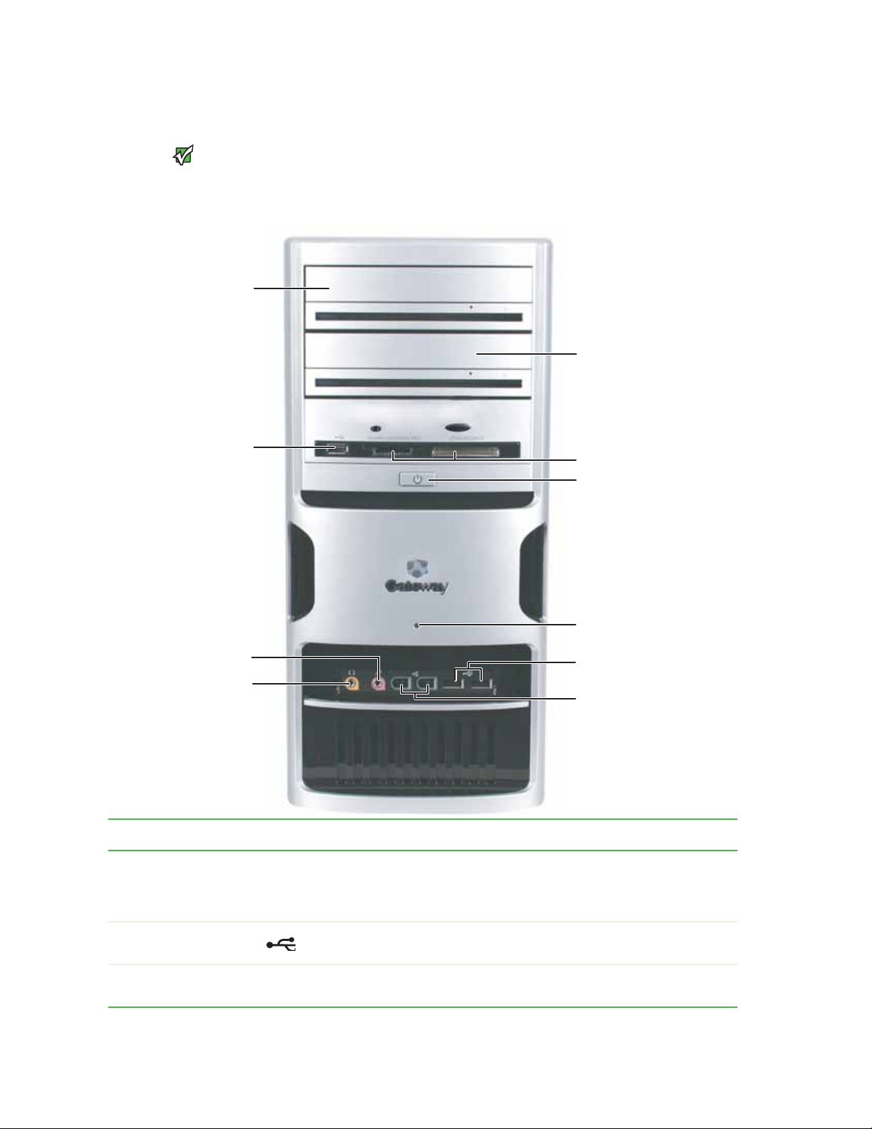
Front
Your computer hardware options and
port locations may vary from the
Important
illustration below.
Optical drive
USB port
(option al)
Optical drive
(option al)
Memory card reader
(option al)
Power button/ power
indicator
Hard drive indicator
Microphone jack
Headphone jack
USB ports (optional)
IEEE 1394 ports
(option al)
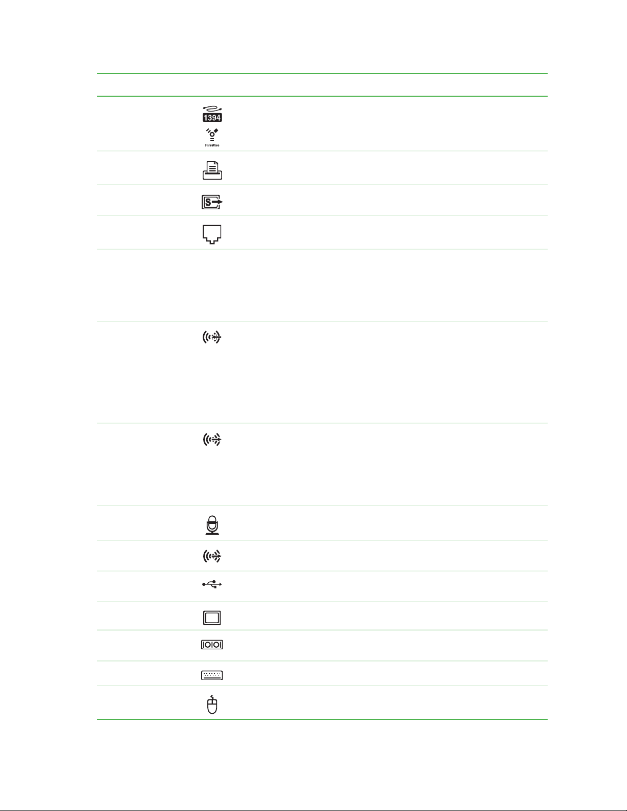
Component Icon Description
Optical drive Use this drive to listen to audio CDs, install games and programs, watch DVDs, and store large
USB ports (optional) Plug a USB (UniversalSerial Bus) device (such as a printer, scanner, camera, keyboard, or
Memory card reader
(optional)
files onto recordable discs (depending on drive type).
This dri ve may be a CD, recordable CD, DVD, or recordable DVD drive. To ident ify your drive t ype
and for more information about your drive, see the User Guide.
mouse) into one of these ports. For more information, see the User Guide..
Insert a memory card from a digital camera, MP3 player, PDA, cellular telephone, or other
devices into the memory card reader.
6
Page 10
www.gateway.com
Component Icon Description
Front
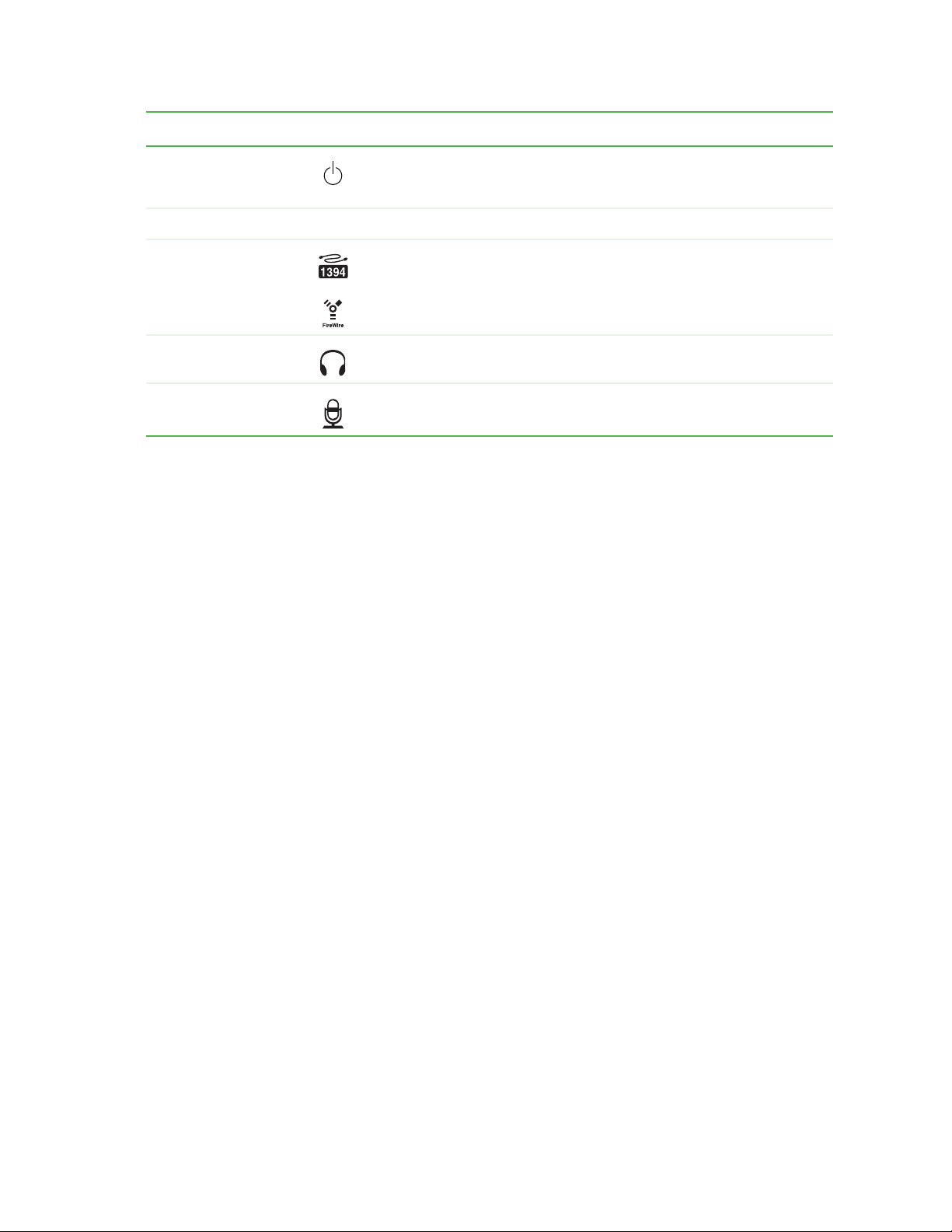
Power button and power
indicator
Hard drive indicator Lights when the hard drive is in use.
IEEE 1394 ports (optional) Plug IEEE 1394 (also known as Firewire
Headphone jack Plug powered, analog front speakers, an external amplifier, or headphones into this jack. This
Microphone jack Plug a microphone into this jack. This jack is color-coded red or pink.
Press this button to turn the power on or off. You can also configure the power button to operate
in Standby/Resume mode or Hibernate mode. The power indicator lights when the computer
is turned on.
®
these 6-pin IEEE 1394 ports. For more information, see the User Guide..
jack is color-coded orange.
or i.Link®) devices (such as a digital camcorder) into
7
Page 11
Chapter 2: Hardware Basics www.gateway.com
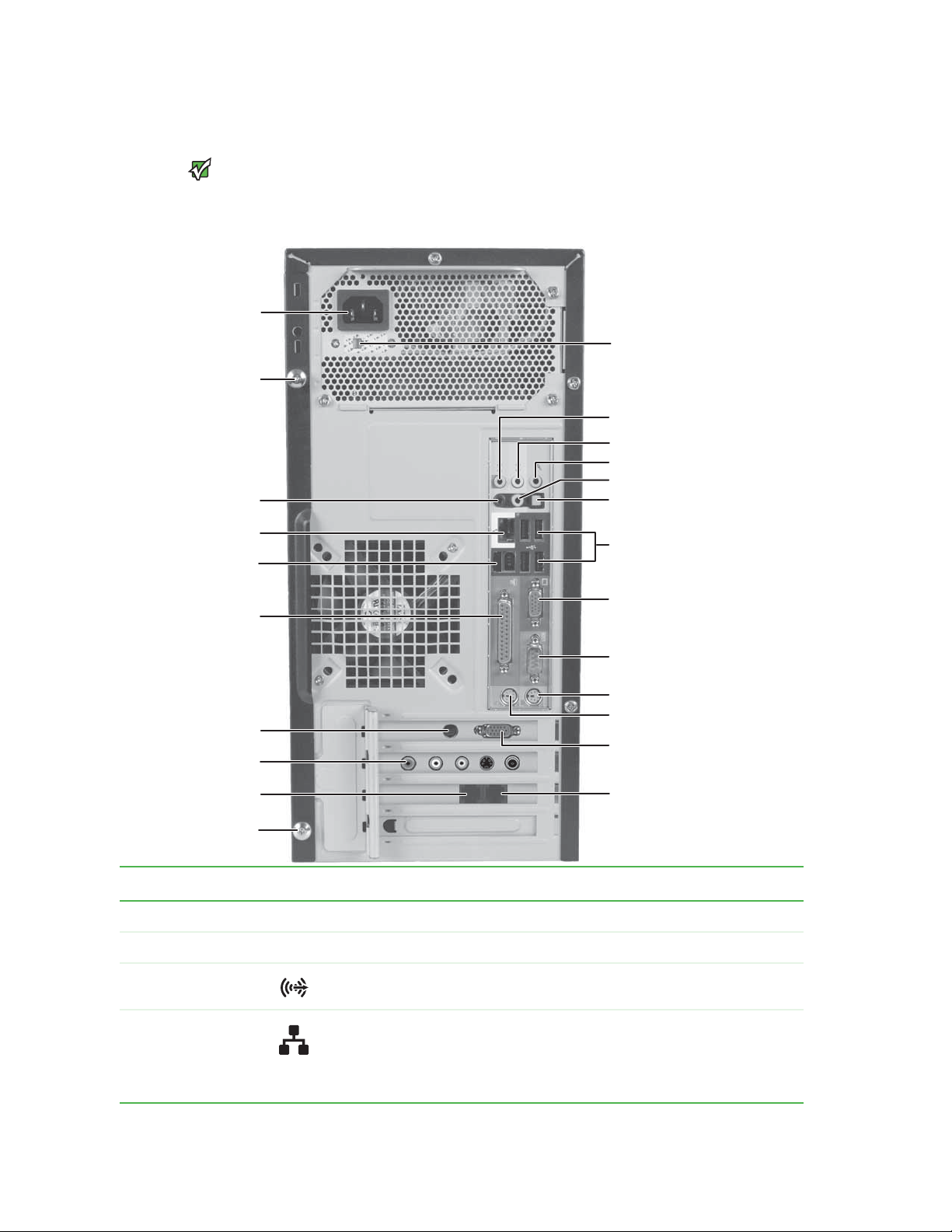
Back
Your computer hardware options and
port locations may vary from the
Case cover thumbscrew
Ethernet (network) jack
IEEE 1394/FireWire™/
i.Link™ ports (optional)
Important
illustration below.
Power connector
Rear speaker jack
(optional)
Parallel port
Voltage switch
Audio in/side speaker jack
Headphone/front speaker jack
Microphone jack
Center/subwoofer jack (optional)
S/PDIF jack (optional)
USB ports
Monitor port
Serial port
PS/2 keyboard port
S-Video out jack
(optional)
TV Tuner (optional)
Modem jack
Case cover thumbscrew
PS/2 mouse port
Monitor port
(optional)
Telephone jack
Component Icon Description
Power connector Plug the power cord into this connector.
Case cover thumbscrews Remove these screws before opening the case.
Rear speaker jack
(black plug) (optional)
Ethernet (network) jack Plug an Ethernet network cable or a device (such as a DSL or cable modem for a broadband
Plug your rear right and left speakers into this optional jack.
For information on configuring this jack, see the User Guide.
Internet connection) into this jack.
For more information, see “Learning about the Internet” in your User Guide which has been
incl uded on yo ur hard drive. To acc ess this guide, click Start, All Programs, then click Gateway
Documentation.
8
Page 12
www.gateway.com
Component Icon Description
Back
IEEE 1394 por ts Plug IEEE 1394 (also known as Firewire® or i.Link®) devices (such as a digital camcorder) into these
Parallel port Plug a parallel device (such as a printer) into this port. For more information, see the User Guide..
S-Video (TV) out jack
(option al)
Modem jack Plug a modem cable into this jack. For more information on modems, see the User Guide..
Voltage switch Before turning on your computer, make sure that this switch is in the correct position for the
Audio input (Line in) jack
(blue plug)
-ORSide speaker jack
6-pin IEEE 1394 ports. For more information, see the User Guide..
Plug a standard S-Video device (such as a television) into this optional jack. Plug the other end
of the cable into an S-Video jack on a television.
correct power available. The switch is preset at the factory with the correct voltage for your area.
In the United States, the utility power is supplied at a nominal 115 volts at 60 Hz. The power
su ppl y sh ould alw ays b e se t to this whe n yo ur co mpu ter is op era tin g in t he U nit ed St ate s. In oth er
areas of the world, such as Europe, the utility power is supplied at 230 volts at 50 Hz. If your
computer is operating in an environment such as this, the voltage switch should be moved to 230.
If the back of your computer has five audio jacks, this jack is user configurable for one of the
following:
Stereo in: Plug an external audio input source (such as a stereo) into this jack so you can record
sound on your computer (Default).
Stereo out: Plug your side left and right speakers into this jack.
For information on configuring this jack, see the User Guide.
If the back of your computer has three audio jacks, this jack is the audio input (line in) jack. Plug
an external audio input source (such as a stereo) into this jack so you can record sound on your
computer.
Headphone/analog
speakers jack (green
plug)
-ORFront speakers jack
Microphone jack (pink
plug)
Center/subwoofer jack
(orange plug) (optional)
USB ports Plug USB (UniversalSerial Bus) devices (such as a USB Iomega™ Zip™ drive, printer, scanner,
Monitor port Plug a monitor into this port.
Serial port Plug a serial device (such as a digital camera) into this port. For more information, see the User
PS/2 keyboard port Plug a Personal System/2
PS/2 mouse port Plug a PS/2 mouse into this port.
If the back of your computer has five audio jacks, this jack is user configurable for one of the
following:
Headphone: Plug headphones or amplified speakers into this jack (Default).
Stereo out: Plug your front left and right speakers into this jack.
For information on configuring this jack, see the User Guide.
If the back of your computer has three audio jacks, this jack is the headphone/analog speaker
(line out) jack. Plug powered speakers, an external amplifier, or headphones into this jack.
Plug a microphone into this jack.
Plug your center speaker and subwoofer into this optional jack.
For information on configuring this jack, see the User Guide.
camera, keyboard, or mouse) into these ports. For more information, see the User Guide..
Guide..
®
(PS/2) keyboard into this port.
9
Page 13

Chapter 2: Hardware Basics www.gateway.com
10
Page 14

CHAPTER 3
Maintenance Basics
• Preventing static electricity discharge
• Opening the case
• Closing the case
• Installing memory
• Replacing the system battery
• Adding or replacing a CD or DVD drive
• Replacing the memory card reader
• Adding or replacing a hard drive
• Replacing the front fan
• Replacing the rear fan
• Replacing the power supply
• Replacing the heat sink and processor
• Replacing the I/O board
• Adding or replacing an expansion card
• Replacing the system board
11
Page 15

CHAPTER 3: Maintenance Basics www.gateway.com
Preventing static electricity discharge
To avoid exposure to dangerous electrical
voltages and moving parts, turn off your
computer and unplug the power cord
and modem and network cables before
ESD can permanently damage
electrostatic discharge-sensitive
components in your computer. Prevent
ESD damage by following ESD guidelines
every time you open the computer case.
To prevent risk of electric shock, do not
insert any object into the vent holes of the
Warning
opening the case.
Caution
Warni ng
power supply.
The components inside your computer are extremely sensitive to static
electricity, also known as electrostatic discharge (ESD).
Before opening the computer case, follow these guidelines:
■ Turn off your computer.
■ Wear a grounding wrist strap (available at most electronics stores) and
attach it to a bare metal part of your computer.
■ Touch a bare metal surface on the back of the computer.
■ Unplug the power cord and the modem and network cables.
Before working with computer components, follow these guidelines:
■ Avoid static-causing surfaces such as carpeted floors, plastic, and packing
foam.
■ Remove components from their antistatic bags only when you are ready
to use them. Do not lay components on the outside of antistatic bags
because only the inside of the bags provide electrostatic protection.
■ Always hold expansion cards by their edges or their metal mounting
brackets. Avoid touching the edge connectors and components on the
cards. Never slide expansion cards or components over any surface.
Opening the case
Removing the side panel
To avoid exposure to dangerous electrical
voltages and moving parts, turn off your
computer, then unplug the power cord
and modem cable before opening the
Warni ng
case.
Your computer case provides easy access to internal components.
To remove the side panel:
1 Follow the instructions in “Preventing static electricity discharge” on
page 12.
2 Shut down your computer, then disconnect the power cord and modem,
network, and all peripheral device cables.
3 Press the power button for ten seconds to drain any residual power from
your computer.
12
Page 16
www.gateway.com
Opening the case
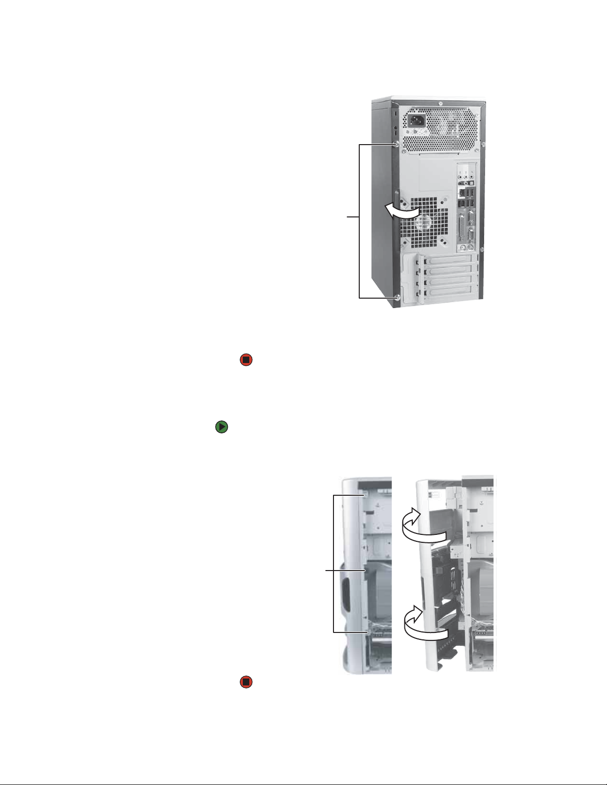
4 Remove the two thumbscrews on the side panel cover.
Thumbscrews
Removing the front bezel
5 Swing the side panel away from the back of your computer, then pull the
panel off.
To remove the front bezel:
1 Press the three bezel retention tabs, then swing the right side of the front
bezel away from the computer and remove it.
Tab s
13
Page 17
CHAPTER 3: Maintenance Basics www.gateway.com
Closing the case
Replacing the front bezel
To replace the front bezel:
1 Engage the tabs on the left side of the bezel with the slots in the left side
of the computer.
2 Swing the right side of the bezel in to engage the tabs on the right side
of the bezel with the slots on the right side of the computer.
3 Press the right side of the bezel firmly until it snaps into place.
Replacing the side panel
To replace the side panel:
1 Make sure that all of the internal cables are arranged inside the computer
so they will not be pinched when you close the computer.
2 Engage the front edge of the side panel with the inside front edge of the
computer, then swing the side panel in toward the back of the computer
to secure it into place.
Thumbscrews
14
3 Replace the side panel thumbscrews.
4 Reconnect the cables and power cord.
Page 18
www.gateway.com
Installing memory
When you upgrade the computer memory, make sure that you install the correct
type of memory module for your computer. Your computer uses DIMM memory.
Installing memory
To install or replace DIMM memory:
1 Remove the side panel by following the instructions in “Removing the side
panel” on page 12.
2 For more stability, place your computer on its side. To avoid scratching the
case, place it on a towel or other non-abrasive surface.
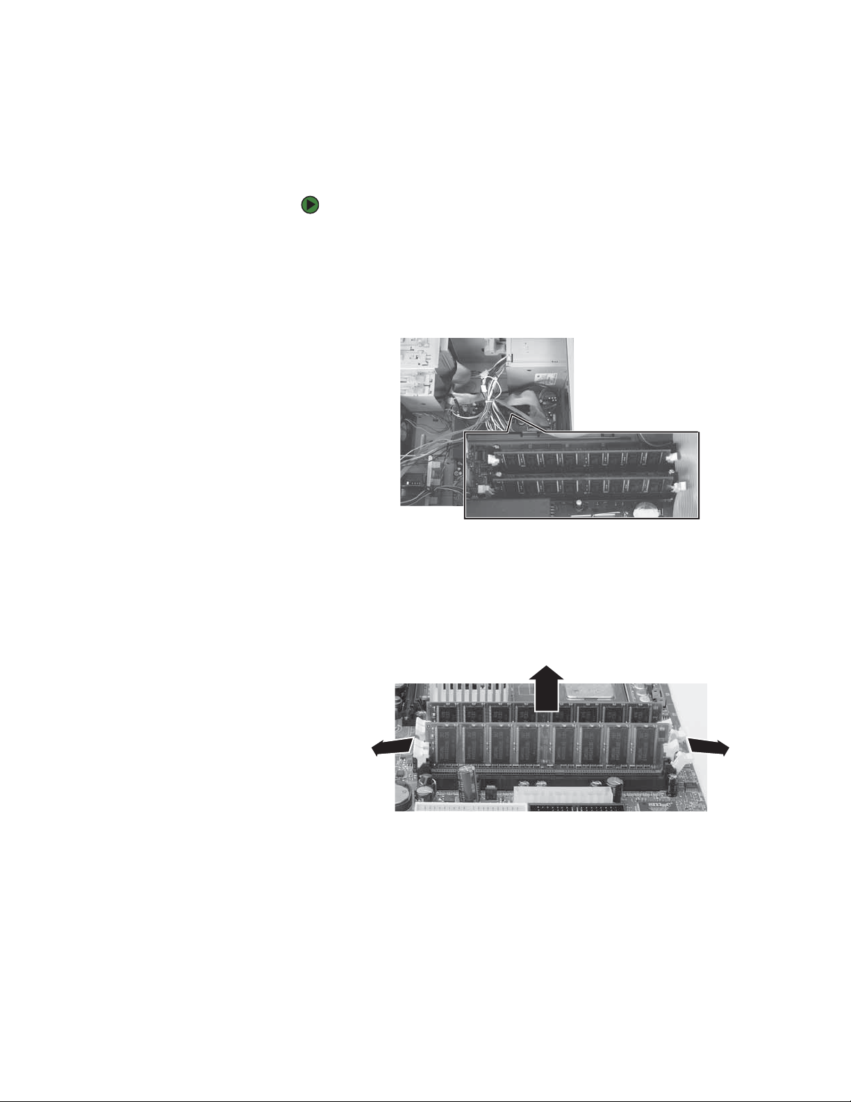
3 Find the memory module banks on your system board.
4 If you are removing a DIMM from the memory module bank, gently pull
the plastic tabs away from the sides of the memory module and remove it.
- OR -
If you are adding a DIMM to an empty memory module bank, gently pull
the plastic tabs away from the sides of the memory module bank.
5 Align the notches on the new DIMM with the notches on the memory
module bank and press the module firmly into the bank. The tabs on the
sides of the memory module should secure the memory module
automatically. When the module is secure, you hear a click.
6 Replace the side panel by following the instructions in “Replacing the side
panel” on page 14.
7 Return your computer to its upright position.
8 Reconnect the cables and the power cord.
15
Page 19
CHAPTER 3: Maintenance Basics www.gateway.com
9 Turn on your computer. Windows starts and the Windows desktop
appears.
10 Click Start, Control Panel, then click Performance and Maintenance (if in
Category view). Click/Double-click
System. The amount of memory in your
computer is shown at the bottom of the System Properties dialog box in
the General tab.
Replacing the system battery
Danger of explosion if battery is
Replace only with the same or equivalent
type recommended by the manufacturer.
Dispose of used batteries following the
Your computer’s battery location may
manufacturer’s instructions.
vary from the illustration below.
Warning
incorrectly replaced.
Important
If the computer clock does not keep time or the settings in the BIOS Setup utility
are not saved when you turn off your computer, replace the system battery. Use
a battery of the same size and voltage as the original battery that was in your
computer.
To replace the battery:
1 Restart your computer.
2 During the restart, press and hold the F1 key. The main menu of the
BIOS Setup utility opens.
3 Write down all the values in the menus and submenus, then exit from the
utility.
4 Shut down your computer.
5 Remove the side panel by following the instructions in “Removing the side
panel” on page 12.
6 For more stability, place your computer on its side. To avoid scratching the
case, place it on a towel or other non-abrasive surface.
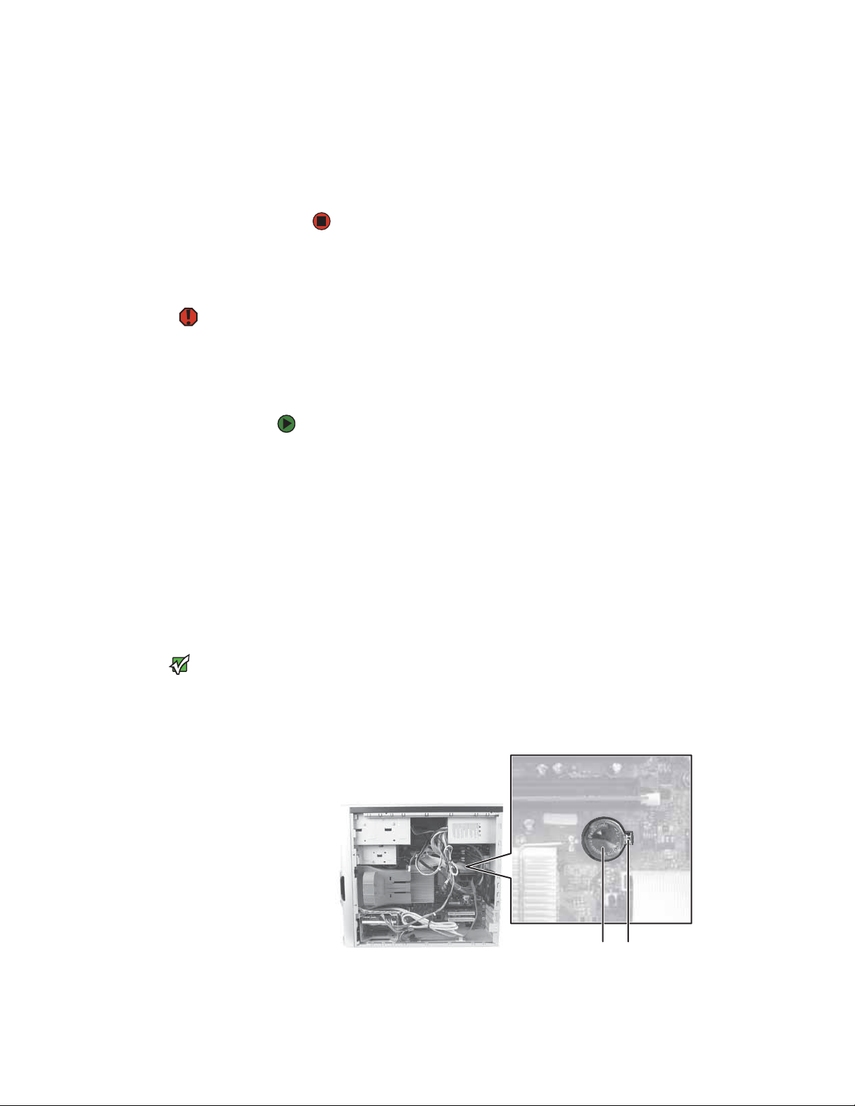
7 Locate the old battery on the system board and note its orientation. You
will need to install the new battery the same way.
8 Push the battery release tab. The battery pops out of the socket.
16
Battery
9 Make sure that the positive (+) side of the new battery is facing up, then
Battery release tab
press the battery into the socket until it snaps into place.
Page 20
www.gateway.com
10 Replace the side panel by following the instructions in “Replacing the side
panel” on page 14.
11 Reconnect all external cables and the power cord.
12 Turn on your computer.
13 Open the BIOS Setup utility.
14 In the BIOS Setup utility, restore any settings that you wrote down in
Step 3.
15 Save all your settings and exit the BIOS Setup utility.
Adding or replacing a CD or DVD drive
Adding or replacing a CD or DVD drive
You need a Phillips screwdriver to add or
The color and shape of your replacement
component's front cover may vary from
Tips & Tricks
replace a CD or DVD drive.
Important
your original component.
To add replace a CD or DVD drive:
1 Remove the side panel by following the instructions in “Removing the side
panel” on page 12.
2 Remove the front bezel by following the instructions in “Removing the
front bezel” on page 13.
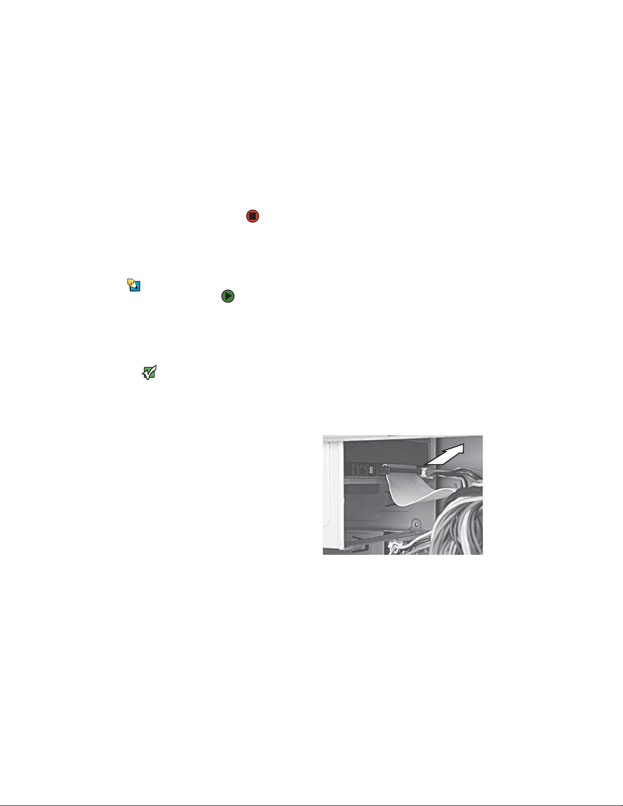
3 If you are replacing an existing drive, disconnect the cables from the drive,
noting their locations and orientation. You will reconnect the cables after
you install the new component. (CD/DVD drive shown.) If you are installing
a new drive, go to Step 6.
17
Page 21
CHAPTER 3: Maintenance Basics www.gateway.com
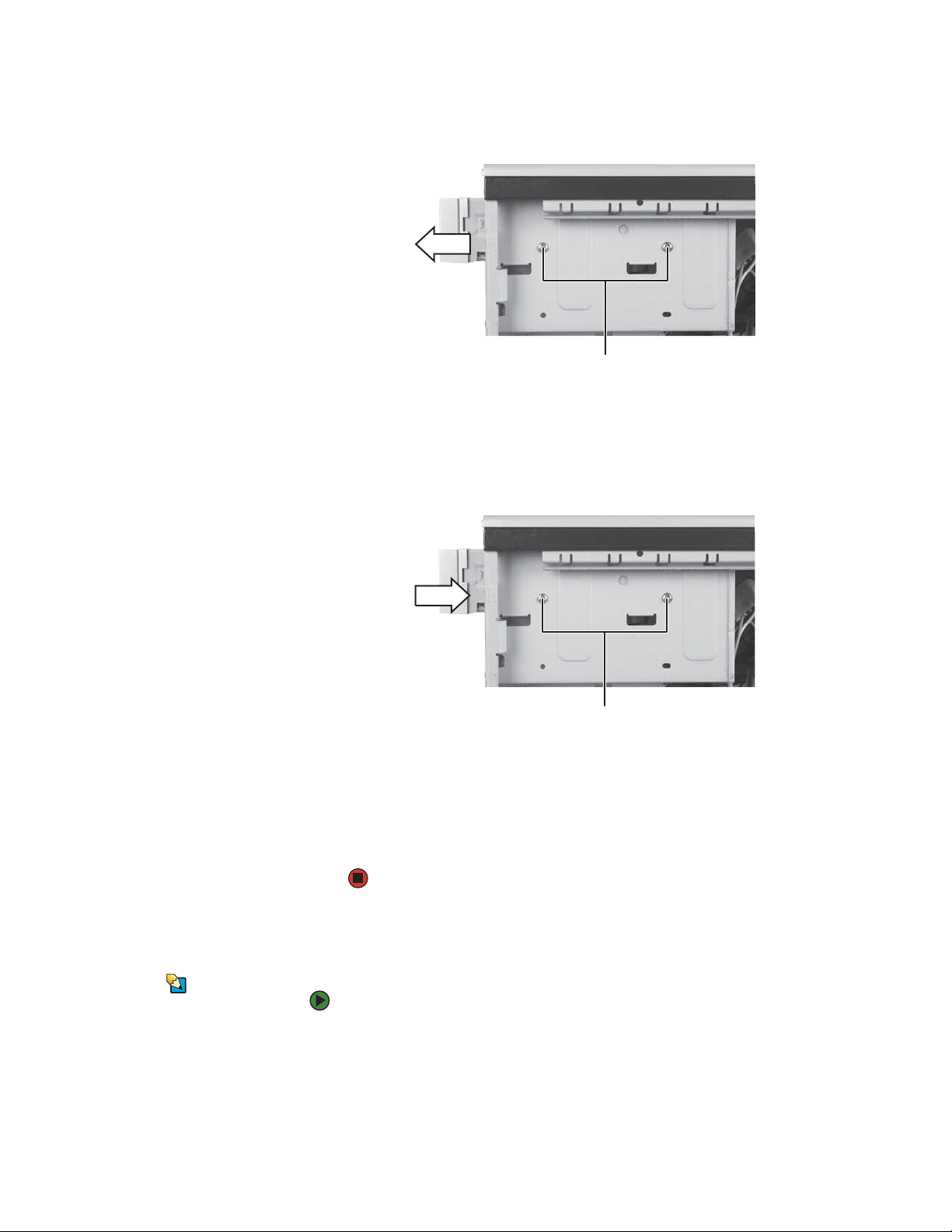
4 Remove the two drive retention screws, then slide the drive forward and
out of the drive bay.
Drive retention screws
5 Note any jumper settings on the old drive and set the jumper on the new
drive to be the same.
6 Slide the new drive into the drive bay, line up the screw holes on the drive
bay with the screw holes on the drive, then replace the two drive retention
screws.
Drive retention screws
7 Reconnect the drive cables using your notes from Step 3.
8 Replace the front bezel by following the instructions in “Replacing the
front bezel” on page 14.
9 Replace the side panel by following the instructions in “Replacing the side
panel” on page 14.
Replacing the memory card reader
You need a Phillips screwdriver to replace
18
Tips & Tricks
To replace the memory card reader:
the memory card reader.
1 Remove the side panel by following the instructions in “Removing the side
panel” on page 12.
2 Remove the front bezel by following the instructions in “Removing the
front bezel” on page 13.
Page 22
www.gateway.com
Adding or replacing a hard drive
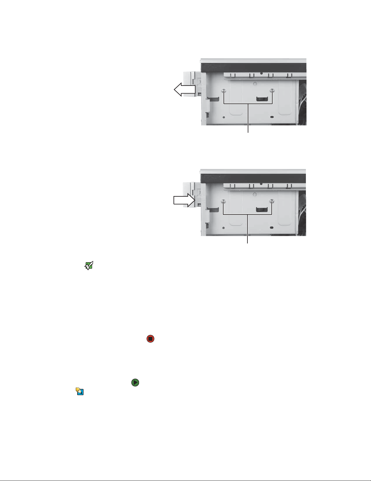
3 Remove the screws holding the card reader in the drive bay.
Screws
4 Disconnect the card reader’s data cable from the system board.
5 Slide the card reader out of the case.
6 Slide the new card reader into the bay from the front of the case.
The color and shape of your replacement
component's front cover may vary from
your original component.
Important
7 Connect the new card reader’s data cable to the system board.
8 Use the screws you removed previously to secure the card reader to the
bay.
9 Reinstall the bezel by following the instructions in “Replacing the front
bezel” on page 14.
10 Reinstall the computer case’s side panel by following the instructions in
“Replacing the side panel” on page 14.
Adding or replacing a hard drive
To add or replace a hard drive:
You need a Phillips screwdriver to add or
Tips & Tricks
replace a hard drive.
1 Remove the side panel by following the instructions in “Removing the side
panel” on page 12.
2 If you are adding a new drive, go to Step 4. If you are replacing an existing
drive, go to the next step.
Screws
19
Page 23
CHAPTER 3: Maintenance Basics www.gateway.com
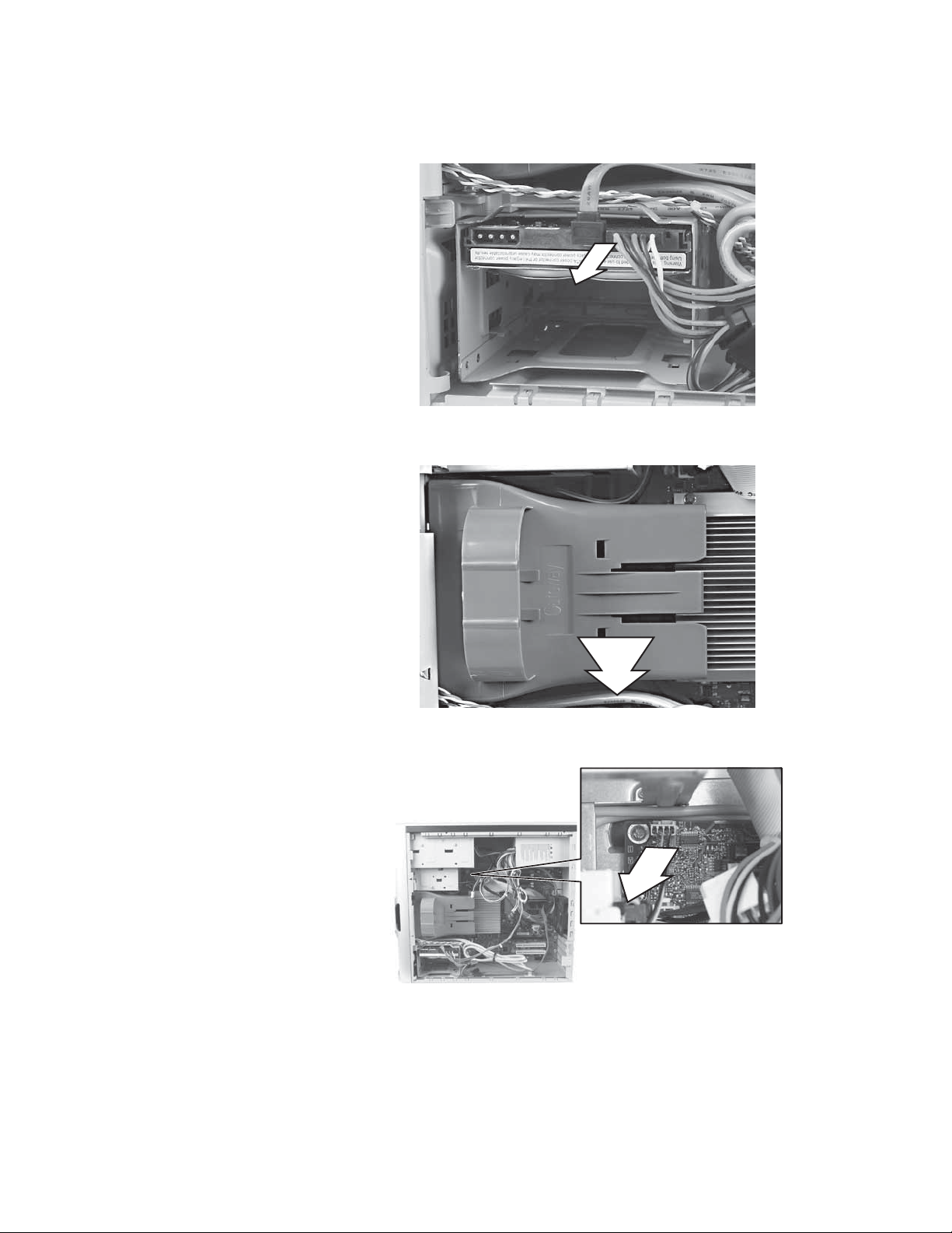
3 Disconnect the drive cables, noting their locations and orientation. (You
will reconnect the cables after you install the new drive.)
4 Remove the front fan assembly by pulling it away from the system board.
20
5 Disconnect the fan cable from the system board.
Page 24
www.gateway.com
Adding or replacing a hard drive
6 Remove the hard drive bay screw.
Hard drive
bay screw
7 Remove the hard drive bay from your computer. You may need to work
the bay out of your computer by rocking the bay back and forth. If you
are adding a new drive, go to Step 10.
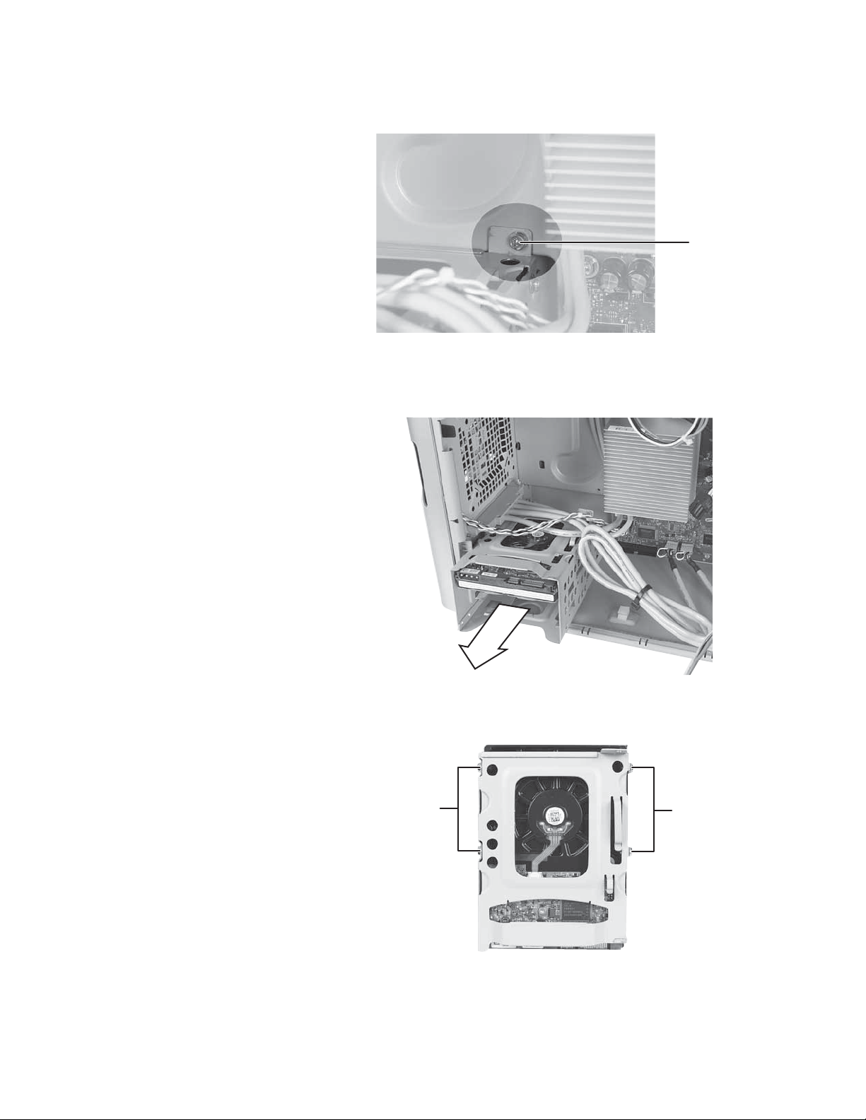
8 Remove the four screws that secure the hard drive to the hard drive bay,
then remove the hard drive from the bay.
ScrewsScrews
21
Page 25

CHAPTER 3: Maintenance Basics www.gateway.com
9 Note any jumper settings on the old drive and set the jumper on the new
drive to be the same.
Jumper
10 Slide the new drive into the drive bay, then secure the drive to the bay
using the four screws you removed previously.
11 Slide the drive bay back into your computer, making sure that the tabs on
the bottom of the bay align with and slide into the slots on the bottom
of your computer.
22
Hard drive bay
mounting slots
12 Secure the drive bay to your computer using the screw you removed
previously.
13 Reconnect the drive cables using your notes from Step 3.
14 Replace the side pane by following the instructions in “Replacing the side
panel” on page 14.
15 Reconnect all external cables and the power cord.
16 Turn on your computer.
17 If Windows does not start, install Windows using the operating system CD
that came with your computer, then install the drivers and applications
using the drivers and applications disc that you created. Follow any
instructions that may be printed on the operating system CD.
Page 26

www.gateway.com
Replacing the front fan
Replacing the front fan
You need a Phillips screwdriver to replace
Tips & Tricks
the front fan.
To replace the front fan:
1 Remove the side panel by following the instructions in “Removing the side
panel” on page 12.
2 Remove the front fan by pulling it away from the system board.
3 Disconnect the fan cable from the system board.
4 Connect the new fan cable to the system board, then insert the new fan
into place.
5 Replace the side panel by following the instructions in “Replacing the side
panel” on page 14.
23
Page 27

CHAPTER 3: Maintenance Basics www.gateway.com
Replacing the rear fan
You need a Phillips screwdriver to replace
Tips & Tricks
the rear fan.
To replace the rear fan:
1 Remove the side panel by following the instructions in “Removing the side
panel” on page 12.
2 Disconnect the fan from the system board.
3 Remove the four screws that secure the fan to the back of the case, then
remove the fan.
24
Screws Screws
4 Place the new fan on the back of your computer, then replace the screws
that secure it to the back cover.
5 Reconnect the fan cable to the system board.
6 Replace the side panel by following the instructions in “Replacing the side
panel” on page 14.
7 Reconnect all external cables and the power cord.
8 Turn on your computer.
Page 28

www.gateway.com
Replacing the power supply
Replacing the power supply
You need a Phillips screwdriver to replace
Tips & Tricks
the power supply.
To replace the power supply:
1 Remove the side panel by following the instructions in “Removing the side
panel” on page 12.
2 Disconnect the power supply cables from all components (such as hard
drives, CD or DVD drives, and the system board), noting their locations and
orientation. (You will reconnect the cables after you install the new power
supply.)
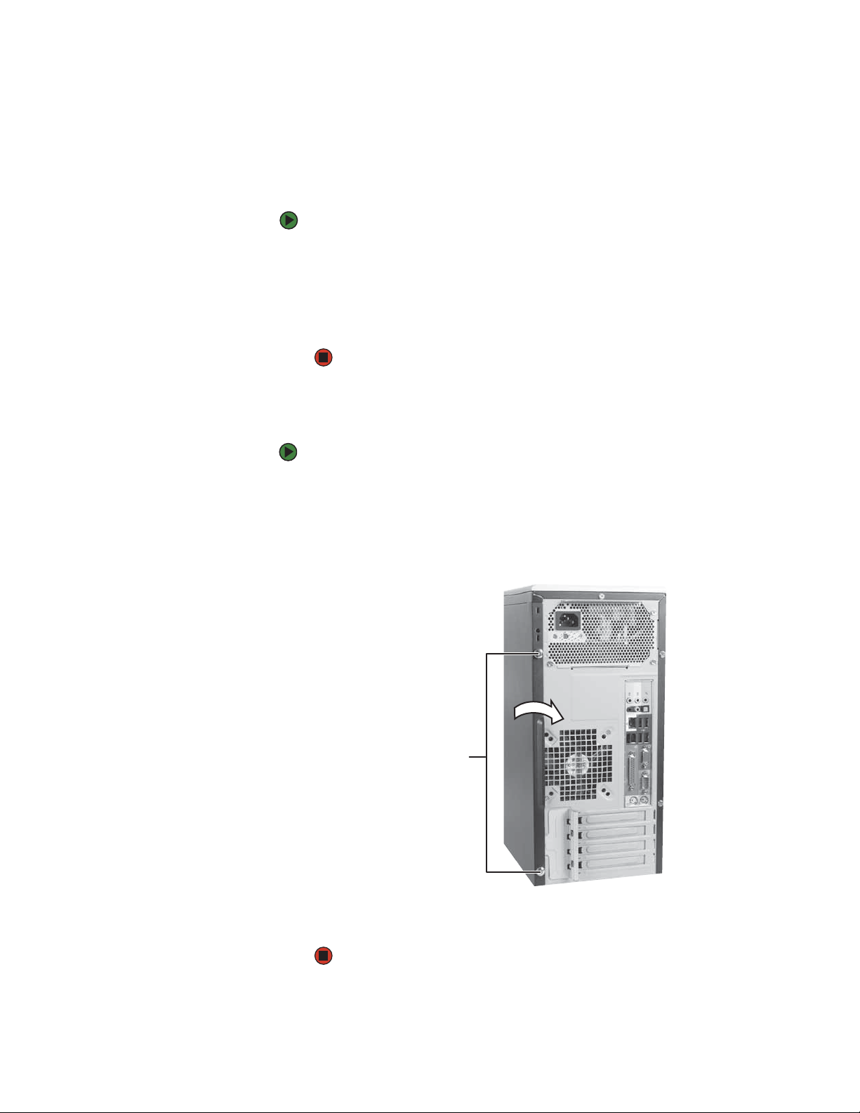
3 Remove the three screws that secure the power supply to your computer.
Screws
4 Slide the power supply away from the back of your computer, then pull
it down and remove it.
5 Install the new power supply into the case, then install the three screws
to secure the power supply to the case.
6 Reconnect the power supply cables using your notes from Step 2.
7 Replace the side panel by following the instructions in “Replacing the side
panel” on page 14.
25
Page 29

CHAPTER 3: Maintenance Basics www.gateway.com
Replacing the heat sink and processor
You need a Phillips screwdriver to replace
Tips & Tricks
the heat sink.
To replace the heat sink and processor:
1 Remove the side panel by following the instructions in “Removing the side
panel” on page 12.
2 For more stability, place your computer on its side. To avoid scratching the
case, place it on a towel or other non-abrasive surface.
3 Remove the fan by pulling it away from the system board.
4 Disconnect the fan cable from the system board.
26
Page 30

www.gateway.com
Replacing the heat sink and processor
5 Loosen the four screws that secure the heat sink to the system board, then
remove the heat sink.
Screws
6 Release the processor by pushing down on the lever and then lifting it
Screws
completely up.
7 Remove the processor from the system board.
8 Install the new processor onto the system board making sure that Pin 1
on the processor (indicated by the silk-screened arrow on the corner of
the processor) aligns with Pin 1 on the processor socket (indicated by the
absence of a pin hole in the processor socket), then return the lever to its
locked position.
9 Place the heat sink on the system board, then tighten the screws that
secure it to the system board.
10 Connect the fan cable to the system board, then insert the fan into place.
11 Replace the side panel by following the instructions in “Replacing the side
panel” on page 14.
27
Page 31

CHAPTER 3: Maintenance Basics www.gateway.com
Replacing the I/O board
The color and shape of your replacement
component's front cover may vary from
your original component.
Important
To replace the front I/O panel:
1 Remove the side panel by following the instructions in “Removing the side
panel” on page 12.
2 Remove the bezel by following the instructions in “Removing the front
bezel” on page 13.
3 Disconnect the cable from the I/O panel.
4 Remove the screw that secures the I/O panel to your computer, then
remove the I/O panel from your computer.
Screw
5 Insert the new I/O panel board into your computer, then replace the screw.
6 Connect the I/O panel cable to the new I/O panel.
7 Replace the front bezel by following the instructions in “Replacing the
front bezel” on page 14.
8 Replace the side panel by following the instructions in “Replacing the side
panel” on page 14.
28
Page 32

www.gateway.com
Adding or replacing an expansion card
To add or replace an expansion card:
1 Remove the side panel by following the instructions in “Removing the side
panel” on page 12.
2 If you are adding a new expansion card, go to the next step. If you are
replacing an expansion card, go to Step 5.
3 Disconnect any cables that are attached to the card, noting their locations
and orientation. (You may need to reconnect the cables after you install
the new card.)
4 Open the card retention lever.
Adding or replacing an expansion card
Card retention lever
Do not touch the contacts on the bottom
part of the expansion card. Touching the
contacts can cause electrostatic damage
Caution
to the card.
5 Remove the old expansion card. You can slightly seesaw the card
end-to-end to loosen the card, but do not bend the card sideways.
6 Install the new card into the expansion slot. You can slightly seesaw the
card end-to-end to help insert the card, but do not bend the card
sideways.
7 Reconnect the expansion card cables (if any) using your notes from Step 3.
8 Replace the side panel.
29
Page 33

CHAPTER 3: Maintenance Basics www.gateway.com
Replacing the system board
To replace the system board:
1 Remove the side panel by following the instructions in “Removing the side
panel” on page 12.
2 Disconnect any expansion card cables from the card and from the system
board, noting their locations and orientation. (You will reconnect the
cables after you reinstall the cards.)
3 Open the card retention lever.
Card retention lever
4 Remove any expansion cards. You can slightly seesaw the card end-to-end
to loosen the card, but do not bend the card sideways.
30
Page 34

www.gateway.com
Replacing the system board
5 Remove the fan by pulling it away from the system board.
6 Disconnect the fan cable from the system board.
7 Find the memory module banks on your system board.
8 Gently pull the plastic tabs away from the sides of the memory modules,
then remove them.
9 Disconnect the power and data cables from the system board, noting their
locations and orientation. (You will reconnect the cables after you install
the new board.)
31
Page 35

CHAPTER 3: Maintenance Basics www.gateway.com
10 Remove the three screws that secure the power supply to your computer.
Screws
11 Slide the power supply away from the back of your computer, then pull
it down and remove it.
12 Remove the seven system board screws.
Screws
Screws
13 Lift the system board up and out of the case.
14 Align the new system board on the screw holes in the case, then secure
it into the case with the screws.
15 If your replacement system board does not include a processor, go to
Step 16.
-OR-
32
If your replacement system board includes a processor, go to Step 20.
Page 36

www.gateway.com
Replacing the system board
16 Loosen the four screws that secure the heat sink to the system board, then
remove the heat sink.
Screws
17 Release the processor from the old system board by pushing down on the
Screws
lever and then lifting it completely up.
18 Remove the processor from the old system board.
19 Install the processor onto the new system board making sure that Pin 1
on the processor (indicated by the silk-screened arrow on the corner of
the processor) aligns with Pin 1 on the processor socket (indicated by the
absence of a pin hole in the processor socket), then return the lever to its
locked position.
20 Install the power supply into the case, then install the three screws to
secure the power supply to the case.
21 Connect the power and data cables using your notes from Step 9.
22 Place the heat sink over the processor, then tighten the screws that secure
it to the system board.
23 Connect the new fan cable to the system board, then insert the new fan
into place.
24 Install the memory you removed previously.
33
Page 37

CHAPTER 3: Maintenance Basics www.gateway.com
25 Reinstall any expansion cards you removed.
26 Replace the side panel by following the instructions in “Replacing the side
panel” on page 14.
© 2006 Gateway, Inc. All rights reserved. Gateway and eMachines are trademarks
or registered trademarks of Gateway, Inc. in the United States and other
countries. All other brands and product names are trademarks or registered
trademarks of their respective companies.
34
Page 38

Index
A
AC power connector 8
audio
audio in jack
center speaker jack 9
front speaker jack 9
headphone jack 9
line in jack 9
line out jack 9
microphone jack 7, 9
rear speaker jack 8
side speaker jack 9
subwoofer jack 9
audio in jack 9
9
B
battery
replacing 16
bezel
removing
replacing 14
broadband connection
connecting 8
13
C
cable modem
connecting 8
cards
adding expansion 29
replacing expansion 29
case
closing 14
opening 12
CD drive
adding
locating drive 6
replacing 17
Certificate of Authenticity 3
closing
computer case 14
front bezel 14
connecting
PS/2 keyboard
PS/2 mouse 9
to Ethernet network 8
to Internet 8
to network 8
connections
audio in
center speaker 9
digital camera 6, 9
digital video camera 7, 9
17
9
9
Ethernet 8
external audio 9
external speakers 9
Firewire 7, 9
front speaker 9
headphone 9
i.Link 7, 9
IEEE 1394 7, 9
keyboard 6, 9
line in 9
line out 9
microphone 7, 9
modem 9
monitor 9
mouse 6 , 9
network 8
parallel 9
power 8
power cord 8
printer 6, 9
PS/2 keyboard 9
PS/2 mouse 9
rear speakers 8
scanner 6, 9
serial 9
side speaker 9
subwoofer 9
S-Video (TV) out 9
USB 6, 9
video camera 7, 9
Zip drive 6, 9
D
digital camera
locating serial port
locating USB port 6, 9
digital video camera
locating IEEE 1394 port
DIMM
See memory
documentation
Using Your Computer
drives
6
CD
DVD 6
recordable CD 6
recordable DVD 6
DSL modem
connecting
DVD drive
adding
locating drive 6
replacing 17
8
17
E
electrostatic discharge (ESD) 12
Ethernet jack 8
expansion card
adding
replacing 29
external audio jack 9
29
F
fan
replacing
Firewire port 7, 9
front bezel
removing
replacing 14
front I/O panel
replacing 28
23, 24
14
G
Gateway contact information 3
H
hard drive
adding 19
indicator 7
replacing 19
headphone jack 7, 9
heat sink
replacing
Hibernate mode 7
9
7, 9
2
I
i.Link port 7, 9
IEEE 1394 port 7, 9
indicators
hard drive
power 7
installing
battery 16
front bezel 13
memory 15
side panel 12
system battery 16
26
7
J
jacks
See connections
35
Page 39

Index www.gateway.com
K
keyboard
PS/2 port
USB port 6, 9
9
L
label
Microsoft Certificate of
Authenticity
product 3
line in jack 9
line out jack 9
M
memory
adding
installing 15
replacing 15
memory card reader
locating 6
replacing 18
microphone jack 7, 9
Microsoft Certificate of
modem
jack 9
monitor
port 9
mouse
PS/2 port 9
USB port 6, 9
15
Authenticity 3
N
network jack 8
O
opening
computer case 12
front bezel 13
optical drive
locating
6
P
parallel port 9
ports
See connections
power
button
connector 8
Hibernate mode 7
indicator 7
Standby/Resume 7
7
power button 7
power supply
replacing
printer
parallel port
USB port 6, 9
PS/2 port
keyboard
3
mouse 9
25
9
9
Z
Zip drive port 9
R
RAM
See memory
recordable drive
Resume mode 7
6
S
safety
static electricity 12
serial port 9
side panel
removing
replacing 12
speaker jack 9
Standby mode 7
starting
computer
static electricity 12
S-Video (TV) out jack 9
system battery
replacing 16
system board
replacing 30
12
7
T
turning off computer 7
turning on computer 7
TV out (S-Video out) jack 9
U
USB port 6, 9
V
video
S-Video out jack
VGA port 9
voltage switch 9
9
W
Windows Product Key Code 3
36
Page 40

Sommaire
Chapitre 1 : À propos de cette référence . . . . . . . . . . . . . . . . . . . . . . . . . . . . . . . . . . . . . .1
À propos de ce guide . . . . . . . . . . . . . . . . . . . . . . . . . . . . . . . . . . . . . . . . . . . . . . . . . . . 2
Accès au Manuel de l'utilisateur . . . . . . . . . . . . . . . . . . . . . . . . . . . . . . . . . . . . . . . . . 2
Coordonnées de Gateway . . . . . . . . . . . . . . . . . . . . . . . . . . . . . . . . . . . . . . . . . . . . . . . 3
Certificat d'authenticité Microsoft. . . . . . . . . . . . . . . . . . . . . . . . . . . . . . . . . . . . . . . . 3
Chapitre 2 : Généralités relatives au matériel . . . . . . . . . . . . . . . . . . . . . . . . . . . . . . . . . .5
Avant . . . . . . . . . . . . . . . . . . . . . . . . . . . . . . . . . . . . . . . . . . . . . . . . . . . . . . . . . . . . . . . . . . . 6
Arrière . . . . . . . . . . . . . . . . . . . . . . . . . . . . . . . . . . . . . . . . . . . . . . . . . . . . . . . . . . . . . . . . . . 8
Chapitre 3 : Généralités relatives à la maintenance . . . . . . . . . . . . . . . . . . . . . . . . . . 11
Prévention de décharge d'électricité statique . . . . . . . . . . . . . . . . . . . . . . . . . . . 12
Ouverture du boîtier . . . . . . . . . . . . . . . . . . . . . . . . . . . . . . . . . . . . . . . . . . . . . . . . . . . 12
Démontage du panneau latéral . . . . . . . . . . . . . . . . . . . . . . . . . . . . . . . . . . . . . 12
Démontage du cadre avant . . . . . . . . . . . . . . . . . . . . . . . . . . . . . . . . . . . . . . . . . 13
Fermeture du boîtier . . . . . . . . . . . . . . . . . . . . . . . . . . . . . . . . . . . . . . . . . . . . . . . . . . . 14
Remontage du cadre avant . . . . . . . . . . . . . . . . . . . . . . . . . . . . . . . . . . . . . . . . . 14
Remontage du panneau latéral . . . . . . . . . . . . . . . . . . . . . . . . . . . . . . . . . . . . . 14
Installation de la mémoire . . . . . . . . . . . . . . . . . . . . . . . . . . . . . . . . . . . . . . . . . . . . . . 15
Remplacement de la batterie système . . . . . . . . . . . . . . . . . . . . . . . . . . . . . . . . . . 16
Ajout ou remplacement d'un lecteur de CD ou de DVD . . . . . . . . . . . . . . . . . 17
Remplacement du lecteur de carte mémoire . . . . . . . . . . . . . . . . . . . . . . . . . . . . 19
Ajout ou remplacement d'un disque dur . . . . . . . . . . . . . . . . . . . . . . . . . . . . . . . . 20
Remplacement du ventilateur avant . . . . . . . . . . . . . . . . . . . . . . . . . . . . . . . . . . . . 23
Remplacement du ventilateur arrière . . . . . . . . . . . . . . . . . . . . . . . . . . . . . . . . . . . 24
Remplacement du bloc d'alimentation . . . . . . . . . . . . . . . . . . . . . . . . . . . . . . . . . . 25
Remplacement du dissipateur thermique et du processeur . . . . . . . . . . . . . . 26
Remplacement de la carte d'E/S . . . . . . . . . . . . . . . . . . . . . . . . . . . . . . . . . . . . . . . . 28
Ajout ou remplacement d'une carte d'extension . . . . . . . . . . . . . . . . . . . . . . . . 29
Remplacement de la carte système . . . . . . . . . . . . . . . . . . . . . . . . . . . . . . . . . . . . . 30
Index. . . . . . . . . . . . . . . . . . . . . . . . . . . . . . . . . . . . . . . . . . . . . . . . . . . . . . . . . . . . . . . . . . . . . . 35
i
Page 41

Sommaire www.gateway.com
ii
Page 42

CHAPITRE 1
À propos de cette référence
• À propos de ce guide
• Accès au Manuel de l'utilisateur
• Coordonnées de Gateway
• Certificat d'authenticité Microsoft.
1
Page 43

Chapitre 1 : À propos de cette référence www.gateway.com
À propos de ce guide
Ce guide contient des informations et des instructions de maintenance qui sont
spécifiques à votre modèle d'ordinateur Gateway. Pour toutes les autres
informations d'ordinateur, veuillez consulter votre Manuel de l'utilisateur en
ligne.
Accès au Manuel de l'utilisateur
En plus de ce guide, le Manuel de l'utilisateur a été inclus sur votre disque dur.
Le Manuel de l'utilisateur est un manuel approfondi facile à lire contenant des
informations sur les sujets suivants :
■ Aide et support technique
■ Configuration et démarrage de votre ordinateur
■ Utilisation et personnalisation de Windows et d'autres logiciels
■ Maîtrise des paramètres audio et vidéo
■ Utilisation d'Internet
■ Protection de vos fichiers
■ Lecture et enregistrement multimédia
■ Réseaux
■ Maintenance et diagnostic
■ Informations légales
Pour accéder au Manuel de l'utilisateur :
■ Cliquez sur Démarrer, Tous les programmes, puis sur Documentation Gateway.
2
Page 44

www.gateway.com
Coordonnées de Gateway
L'étiquette se trouvant sur le côté du boîtier de votre ordinateur comporte des
informations qui permettent d'identifier le modèle et le numéro de série de
votre ordinateur. Le service clientèle Gateway aura besoin de cette information
lorsque vous appellerez pour obtenir de l'aide.
Coordonnées de Gateway
On
lin
e
T
e
s
c
up
h
Sup
po
r
t
po
:
T
rt P
e
ch
ho
Sup
n
e
:
p
(U
o
r
.
t
S
H
.)
(
ou
C
an
r
s:
ad
a)
9
0
0
4
3
94
Online support:
Tech Support Phone: (U.S.)
Tech Support Hours:
(Canada)
9004394
Certificat d'authenticité Microsoft.
L'étiquette de certificat d'authenticité Microsoft se trouvant à l'arrière ou sur le
côté de votre ordinateur inclut le code d'identification de produit de votre
système d'exploitation. Si vous deviez un jour réinstaller Windows depuis le CD
ou DVD d'installation, il vous faudra entrer ces numéros pour activer Windows.
3
Page 45

Chapitre 1 : À propos de cette référence www.gateway.com
4
Page 46

CHAPITRE 2
Généralités relatives au matériel
•Avant
• Arrière
5
Page 47

Chapitre 2 : Généralités relatives au matériel www.gateway.com
Avant
Les options matérielles et emplacements
des ports de votre ordinateur peuvent
être différents de l'illustration ci-dessous.
Important
Lecteur optique
Port USB
(en option)
Lecteur optique
(en option)
Lecteur de carte
mémoire (en option)
Interrupteur
d'alimentation / Voyant
d'alimentation
Voyant du disque dur
Prise de microphone
Prise pour casque
d’écoute
Ports USB (en option)
Ports IEEE 1394 (en
option)
Composant Icône Description
Lecteur optique Utilisez ce lecteur pour écouter des CD audio, installer des jeux et des programmes, regarder
Ports USB (en option) Branchez un périphérique USB (Universal Serial Bus) (tel qu'une imprimante, un scanneur, un
des DVD et stocker de gros fichiers sur des disques enregistrables (selon le type de lecteur).
Ce lecteur peut être un lecteur de CD, de CD enregistrable, de DVD ou de DVD enregistrable.
Pour identifier votre lecteur et obtenir des informations complémentaires sur le lecteur,
reportez-vous au Manuel de l'utilisateur.
appareil photo, un clavier ou une souris) dans un de ces ports. Pour plus d'informations,
consultez le Manuel de l'utilisateur.
6
Page 48

www.gateway.com
Composant Icône Description
Avant
Lecteur de carte mémoire
(en option)
Interrupteur d'alimentation
et voyant d'alimentation
Voyant du disque dur S'allume lorsque le disque dur est utilisé.
Ports IEEE 1394 (en option) Branchez un appareil IEEE 1394 (aussi connu sous le nom de Firewire
Prise pour casque d'écoute Branchez dans cette prise des haut-parleurs analogiques avant, un amplificateur externe ou
Prise de microphone Branchez un microphone dans cette prise. Cette prise est chromocodée rouge ou rose.
Insérez la carte mémoire d'un appareil photo numérique, d'un lecteur MP3, d'un PDA ou d'un
téléphone portable ou d'autres périphériques dans le lecteur de carte mémoire.
Appuyez sur cet interrupteur pour mettre l'appareil sous tension ou hors tension. Vous pouvez
également configurer ce bouton pour qu'il fonctionne en mode Veille/Reprise ou en mode
Veille prolongée. Le voyant d'alimentation s'allume lorsque l'ordinateur est sous tension.
®
caméscope numérique) dans l'un des ports IEEE 1394 à 6 broches. Pour plus d'informations,
consultez le Manuel de l'utilisateur.
un casque d'écoute. Cette prise est chromocodée orange.
ou de i.Link®) (tel qu'un
7
Page 49

Chapitre 2 : Généralités relatives au matériel www.gateway.com
Arrière
Les options matérielles et emplacements
des ports de votre ordinateur peuvent
être différents de l'illustration ci-dessous.
Connecteur
d’alimentation
Vis de serrage du couvercle du
Prise pour haut-parleur
arrière (en option)
Prise Ethernet (réseau)
Ports IEEE 1394/FireWire™/
i.Link™ (en option)
Port parallèle
Important
boîtier
Commutateur de tension
Prise d'entrée audio/du
haut-parleur latéral
Prise pour casque d'écoute/du haut-parleur avant
Prise de microphone
Prise pour haut-parleur central/caisson de basses (en option)
Prise S/PDIF (en option)
Ports USB
Port de moniteur
Port série
Port de clavier PS/2
Prise de sortie
S-vidéo (en option)
Tuner TV (en option)
Prise de modem
Vis de serrage du couvercle
du boîtier
Port de souris PS/2
Port de moniteur
(en option)
Prise de téléphone
Composant Icône Description
Connecteur d'alimentation Branchez le cordon d'alimentation dans ce connecteur.
Vis de serrage du couvercle
du boîtier
Prise pour haut-parleur
arrière (en option)
Prise Ethernet (réseau) Branchez un câble réseau Ethernet ou un périphérique (tel qu'un modem DSL ou câble pour une
Enlevez ces vis avant d'ouvrir le boîtier.
Branchez vos haut-parleurs arrière droit et gauche dans cette prise optionnelle.
Pour plus d'informations sur la configuration de cette prise, consultez le Manuel de l'utilisateur.
connexion Internet haut débit) dans cette prise.
Pour plus d'informations, consultez « Découvrir Internet » dans le Manuel de l'utilisateur qui se
trouve sur votre disque dur. Pour accéder à ce manuel, cliquez sur Démarrer, Tou s le s
programmes et ensuite sur Documentation Gateway.
8
Page 50

www.gateway.com
Composant Icône Description
Arrière
Ports IEEE 1394 Branchez un appareil IEEE 1394 (aussi connu sous le nom de Firewire® ou de i.Link®) (tel qu'un
Port parallèle Branchez un périphérique parallèle (tel qu'une imprimante) dans ce port. Pour plus
Prise de sortie S-vidéo (TV)
(en option)
Prise de modem Branchez un câble de modem dans cette prise. Pour plus d'informations sur les modems,
Commutateur de tension Avant de mettre l'ordinateur sous tension, assurez-vous que ce commutateur se trouve dans la
Prise d'entrée audio (Line in
; prise bleue)
- OU Prise pour haut-parleur
latéral
caméscope numérique) dans l'un des ports IEEE1394 à 6 broches. Pour plus d'informations,
consultez le Manuel de l'utilisateur.
d'informations, consultez le Manuel de l'utilisateur.
Branchez un périphérique S-vidéo standard (comme un téléviseur) dans cette prise optionnelle.
Branchez l'autre extrémité du câble dans la prise S-vidéo d'un téléviseur.
consultez le Manuel de l'utilisateur.
position correspondant à la tension disponible. Ce commutateur est configuré à l'usine sur la
tension correspondant à votre région.
Aux États-Unis, l'alimentation est fournie à une tension nominale de 115 volts à 60 Hz.
L'alimentation doit toujours être réglée sur ces valeurs si l'ordinateur est utilisé aux États-Unis.
Dans d'autres régions du monde, comme l'Europe, l'alimentation est fournie à une tension
nominale de 230 volts à 50 Hz. Si votre ordinateur fonctionne dans un environnement tel que
celui-là, le commutateur de tension doit être positionné sur 230.
Si l'arrière de votre ordinateur est doté de cinq prises audio, cette prise peut être configurée par
l'utilisateur pour l'une des options suivantes :
Entrée stéréo : Branchez une source audio externe (telle qu'une stéréo) dans cette prise afin
de pouvoir enregistrer de l'audio sur l'ordinateur (paramètre par défaut).
Sortie stéréo : Branchez vos haut-parleurs latéraux droit et gauche dans cette prise.
Pour plus d'informations sur la configuration de cette prise, consultez le Manuel de l'utilisateur.
Si l'arrière de votre ordinateur est doté de trois prises audio, cette prise est la prise d'entrée audio
(Line in). Branchez une source audio externe (telle qu' une stéréo) dans cette prise afin de pouvoir
enregistrer de l'audio sur l'ordinateur.
Prise pour casque
d'écoute/haut-parleurs
analogiques (prise verte)
- OU Prise pour haut-parleurs
avant
Prise de microphone (prise
rose)
Prise pour haut-parleur
central/caisson de basses
(prise orange ; en option)
Ports USB Branchez des périphériques USB (Universal Serial Bus) (tels qu'un lecteur USB Iomega™ Zip™, une
Port de moniteur Branchez un moniteur dans ce port.
Port série Branchez un périphérique série (tel qu'un appareil photo numérique) dans ce port. Pour plus
Si l'arrière de votre ordinateur est doté de cinq prises audio, cette prise peut être configurée par
l'utilisateur pour l'une des options suivantes :
Casque d'écoute : Branchez les casques d'écoute ou les haut-parleurs amplifiés dans cette prise
(paramètre par défaut).
Sortie stéréo : Branchez vos haut-parleurs avant droit et gauche dans cette prise.
Pour plus d'informations sur la configuration de cette prise, consultez le Manuel de l'utilisateur.
Si l'arrière de votre ordinateur est doté de trois prises audio, cette prise est la prise pour casque
d'écoute/haut-parleur analogique (Line out). Branchez dans cette prise des haut-parleurs
amplifiés, un amplificateur externe ou un casque d'écoute.
Branchez un microphone dans cette prise.
Branchez votre haut-parleur central et votre caisson de basses dans cette prise optionnelle.
Pour plus d'informations sur la configuration de cette prise, consultez le Manuel de l'utilisateur.
imprimante, un scanneur, un appareil photo, un clavier ou une souris) dans ces ports. Pour plus
d'informations, consultez le Manuel de l'utilisateur.
d'informations, consultez le Manuel de l'utilisateur.
9
Page 51

Chapitre 2 : Généralités relatives au matériel www.gateway.com
Composant Icône Description
Port de clavier PS/2 Branchez un clavier PS/2 (Personal System/2®) dans ce port.
Port de souris PS/2 Branchez une souris PS/2 dans ce port.
10
Page 52

CHAPITRE 3
Généralités relatives à la maintenance
• Prévention de décharge d'électricité statique
•Ouverture du boîtier
•Fermeture du boîtier
• Installation de la mémoire
• Remplacement de la batterie système
• Ajout ou remplacement d'un lecteur de CD ou de DVD
• Remplacement du lecteur de carte mémoire
• Ajout ou remplacement d'un disque dur
• Remplacement du ventilateur avant
• Remplacement du ventilateur arrière
• Remplacement du bloc d'alimentation
• Remplacement du dissipateur thermique et du
processeur
• Remplacement de la carte d'E/S
• Ajout ou remplacement d'une carte d'extension
• Remplacement de la carte système
11
Page 53

Chapitre 3 : Généralités relatives à la maintenance www.gateway.com
Prévention de décharge d'électricité statique
Pour éviter l'exposition aux pièces
mobiles et aux tensions électriques
dangereuses, éteignez votre ordinateur
et débranchez le cordon d'alimentation,
le câble de modem et les câbles réseau
Les décharges électrostatiques peuvent
endommager définitivement les
composants de votre ordinateur qui y
sont sensibles. Pour éviter les dommages
dus aux décharges électrostatiques,
suivez les consignes les concernant
chaque fois que vous ouvrez le boîtier de
Pour éviter le risque de choc électrique,
n'insérez pas d'objet dans les orifices
d'aération du bloc d'alimentation.
Avertissement
avant d'ouvrir le boîtier.
Mise en garde
l'ordinateur.
Avertissement
Les composants se trouvant à l'intérieur de votre ordinateur sont extrêmement
sensibles à l'électricité statique, appelée également décharge électrostatique.
Avant d'ouvrir le boîtier de l'ordinateur, suivez ces consignes :
■ Éteignez votre ordinateur.
■ Portez une dragonne mise à la masse (disponible dans la plupart des
magasins électroniques) et fixez-la à une pièce de métal nu de votre
ordinateur.
■ Touchez une surface métallique nue à l'arrière de l'ordinateur.
■ Débranchez le cordon d'alimentation ainsi que le modem et les câbles
réseau.
Avant de travailler avec des composants, suivez ces directives :
■ Évitez les surfaces causant de l'électricité statique, telles que les sols
recouverts de tapis, le plastique et la mousse d'emballage.
■ N'enlevez les composants de leurs sacs antistatiques que lorsque vous êtes
prêt à les utiliser. Ne déposez pas les composants sur la partie externe des
sacs antistatiques parce que seul l'intérieur des sacs fournit une protection
électrostatique.
■ Tenez toujours les cartes d'extension par les bords ou leurs supports de
fixation métalliques. Évitez de toucher les connecteurs latéraux et les
composants des cartes. Ne faites jamais glisser les cartes d'extension ou
composants sur une surface.
Ouverture du boîtier
Le boîtier de votre ordinateur permet d'accéder facilement aux composant
internes.
Démontage du panneau latéral
Pour éviter l'exposition aux pièces
mobiles et aux tensions électriques
dangereuses, éteignez votre ordinateur,
d'alimentation et le câble du modem
12
Avertissement
puis débranchez le cordon
avant d'ouvrir le boîtier.
Pour démonter le panneau latéral, procédez comme suit :
1 Suivez les instructions de « Prévention de décharge d'électricité statique »
à la page 12.
2 Arrêtez l'ordinateur, puis débranchez le cordon d'alimentation et les
câbles du modem, du réseau et de tous les périphériques.
3 Appuyez sur l'interrupteur pendant dix secondes pour purger l'ordinateur
de toute électricité restante.
Page 54

www.gateway.com
Ouverture du boîtier
4 Enlevez les deux vis à oreilles du couvercle du panneau latéral.
Vis à oreilles
Démontage du cadre avant
5 Dégagez le panneau latéral en l'écartant de l'arrière de l'ordinateur, puis
retirez-le.
Pour démonter le cadre avant, procédez comme suit :
1 Appuyez sur les trois onglets de maintien du cadre, puis faites pivoter le
côté droit du cadre en l'écartant de l'ordinateur et retirez-le.
Onglets
13
Page 55

Chapitre 3 : Généralités relatives à la maintenance www.gateway.com
Fermeture du boîtier
Remontage du cadre avant
Pour remonter le cadre avant, procédez comme suit :
1 Insérez les onglets sur le côté gauche du cadre dans les logements sur le
côté gauche de l'ordinateur.
2 Faites pivoter le côté droit du cadre pour engager les onglets sur le côté
droit du cadre dans les logements sur le côté droit de l'ordinateur.
3 Appuyez fermement sur le côté droit du cadre jusqu'à ce qu'il se mette
en place.
Remontage du panneau latéral
Pour remonter le panneau latéral, procédez comme suit :
1 Assurez-vous que les câbles internes sont disposés dans l'ordinateur de
sorte qu'ils ne seront pas pincés lors de la fermeture de l'ordinateur.
2 Positionnez le bord avant du panneau latéral à l'intérieur du bord avant
de l'ordinateur, puis faites pivoter le panneau latéral vers l'arrière de
l'ordinateur pour le mettre en place.
Vis à oreilles
14
3 Revissez les vis à oreilles du panneau latéral.
4 Reconnectez les câbles et le cordon d'alimentation.
Page 56

www.gateway.com
Installation de la mémoire
Lorsque vous mettez à niveau la mémoire de l'ordinateur, veillez à installer le
type de module de mémoire correct pour l'ordinateur. Votre ordinateur utilise
des barrettes de mémoire DIMM.
Pour installer ou remplacer des barrettes de mémoire DIMM, procédez comme
suit :
1 Démontez le panneau latéral en suivant les instructions de la section
« Démontage du panneau latéral » à la page 12.
2 Pour une meilleure stabilité, posez l'ordinateur sur son flanc. Pour éviter
de rayer le boîtier, posez-le sur une serviette ou sur une surface non
abrasive.
3 Localisez les connecteurs des modules de mémoire sur la carte système.
Installation de la mémoire
4 Si vous enlevez une barrette DIMM d'un connecteur de module de
mémoire, écartez soigneusement les onglets en plastique des côtés du
module de mémoire et enlevez la barrette.
- OU -
Si vous ajoutez une barrette DIMM à un connecteur de module de
mémoire vide, écartez soigneusement les onglets en plastique des côtés
du connecteur de module de mémoire.
5 Alignez les encoches de la nouvelle barrette DIMM aux encoches du
connecteur de module de mémoire et enfoncez fermement le module
dans le connecteur. Les onglets situés sur les côtés du module de mémoire
doivent fixer automatiquement le module de mémoire. Vous entendrez un
déclic lorsque le module sera correctement logé.
15
Page 57

Chapitre 3 : Généralités relatives à la maintenance www.gateway.com
6 Remontez le panneau latéral en suivant les instructions de la section
« Remontage du panneau latéral » à la page 14.
7 Replacez l'ordinateur en position verticale.
8 Reconnectez les câbles et le cordon d'alimentation.
9 Allumez votre ordinateur. Windows démarre et le bureau de Windows
s'affiche.
10 Cliquez sur Démarrer, Panneau de configuration, puis sur Performances et
maintenance
double-cliquez sur
(si vous êtes en affichage par catégories). Cliquez ou
Système. La quantité de mémoire installée sur votre
ordinateur est indiquée en bas de la boîte de dialogue Propriétés système
de l'onglet Général.
Remplacement de la batterie système
Danger d'explosion si la batterie est
remplacée de façon inadéquate.
Remplacez la batterie par une autre
identique ou équivalente recommandée
par le fabricant. Jetez les batteries
épuisées en respectant les directives du
L'emplacement de la batterie de votre
ordinateur peut être différent de celui
indiqué dans l'illustration ci-dessous.
Avertissement
fabricant.
Important
Si l'horloge système ne mesure pas correctement le temps ou si les paramètres
de configuration du BIOS ne sont pas enregistrés lorsque vous arrêtez votre
ordinateur, remplacez la batterie système. Utilisez une batterie de même taille
et de même tension que celle initialement fournie avec l'ordinateur.
Pour remplacer la batterie, procédez comme suit :
1 Redémarrez l’ordinateur.
2 Lors du redémarrage, maintenez la touche F1 enfoncée. Le menu principal
de l'utilitaire de configuration du BIOS s'ouvre.
3 Notez toutes les valeurs des menus et sous-menus, puis quittez l'utilitaire.
4 Arrêtez l'ordinateur.
5 Démontez le panneau latéral en suivant les instructions de la section
« Démontage du panneau latéral » à la page 12.
6 Pour une meilleure stabilité, posez l'ordinateur sur son flanc. Pour éviter
de rayer le boîtier, posez-le sur une serviette ou sur une surface non
abrasive.
7 Localisez la batterie sur la carte système et notez son orientation. La
nouvelle batterie devra être installée de façon identique.
8 Poussez l'onglet de dégagement de la batterie. La batterie sort de son
support.
16
Page 58

www.gateway.com
Ajout ou remplacement d'un lecteur de CD ou de DVD
Batterie
9 Assurez-vous que le pôle positif (+) de la nouvelle batterie est orienté vers
Onglet de dégagement
le haut, puis enfoncez la batterie dans le support jusqu'à ce qu'elle
s'enclenche en position.
10 Remontez le panneau latéral en suivant les instructions de la section
« Remontage du panneau latéral » à la page 14.
11 Reconnectez tous les câbles externes et le cordon d'alimentation.
12 Allumez votre ordinateur.
13 Ouvrez l'utilitaire de configuration du BIOS.
14 Dans l'utilitaire de configuration du BIOS, restaurez tous les paramètres
que vous avez notés à l'étape 3.
15 Enregistrez tous les paramètres et quittez l'utilitaire de configuration du
BIOS.
Ajout ou remplacement d'un lecteur de CD ou de DVD
Munissez-vous d'un tournevis cruciforme
pour ajouter ou remplacer un lecteur de
Conseils et astuces
CD ou de DVD.
Pour ajouter ou remplacer un lecteur de CD ou de DVD, procédez comme suit:
1 Démontez le panneau latéral en suivant les instructions de la section
« Démontage du panneau latéral » à la page 12.
2 Démontez le cadre avant en suivant les instructions de la section
« Démontage du cadre avant » à la page 13.
17
Page 59

Chapitre 3 : Généralités relatives à la maintenance www.gateway.com
La couleur et la forme du panneau avant
du composant de remplacement peuvent
être différentes de celles du composant
Important
d'origine.
3 Si vous remplacez un lecteur existant, débranchez les câbles du lecteur en
prenant note de leur emplacement et de leur orientation. Vous
rebrancherez les câbles lorsque le nouveau composant aura été installé.
(Lecteur de CD/DVD affiché.) Si vous installez un nouveau lecteur, passez
à l'étape 6.
4 Enlevez les deux vis de maintien du lecteur, puis faites glisser le lecteur
vers l'avant pour le sortir de la baie.
Vis de maintien du lecteur
5 Prenez note des paramètres du cavalier de l'ancien lecteur et configurez
le cavalier du nouveau lecteur de la même manière.
6 Insérez le nouveau lecteur dans la baie, alignez les trous de vis de la baie
avec les trous de vis du lecteur, puis réinsérez les deux vis de maintien du
lecteur.
Vis de maintien du lecteur
7 Rebranchez les câbles du lecteur en utilisant les notes que vous avez prises
à l'étape 3.
18
Page 60

www.gateway.com
8 Remontez le cadre avant en suivant les instructions de la section
Remplacement du lecteur de carte mémoire
« Remontage du cadre avant » à la page 14.
9 Remontez le panneau latéral en suivant les instructions de la section
« Remontage du panneau latéral » à la page 14.
Remplacement du lecteur de carte mémoire
Munissez-vous d'un tournevis cruciforme
Conseils et astuces
pour remplacer le lecteur de carte
mémoire.
Pour remplacer le lecteur de carte mémoire, procédez comme suit :
1 Démontez le panneau latéral en suivant les instructions de la section
« Démontage du panneau latéral » à la page 12.
2 Démontez le cadre avant en suivant les instructions de la section
« Démontage du cadre avant » à la page 13.
3 Enlevez les vis qui maintiennent le lecteur de carte dans la baie.
Vis
4 Débranchez le câble de données du lecteur de carte de la carte système.
5 Glissez le lecteur de carte hors du boîtier.
La couleur et la forme du panneau avant
du composant de remplacement peuvent
être différentes de celles du composant
Important
d'origine.
Vis
6 Insérez le nouveau lecteur de carte dans la baie en le glissant par l'avant
du boîtier.
7 Branchez le câble de données du nouveau lecteur de carte à la carte
système.
8 Fixez le lecteur de carte dans la baie à l'aide des vis précédemment
enlevées.
19
Page 61

Chapitre 3 : Généralités relatives à la maintenance www.gateway.com
9 Réinstallez le cadre en suivant les instructions de la section « Remontage
du cadre avant » à la page 14.
10 Réinstallez le panneau latéral du boîtier de l'ordinateur en suivant les
instructions de la section « Remontage du panneau latéral » à la page 14.
Ajout ou remplacement d'un disque dur
Pour ajouter ou remplacer un disque dur, procédez comme suit :
Munissez-vous d'un tournevis cruciforme
Conseils et astuces
pour ajouter ou remplacer un disque dur.
1 Démontez le panneau latéral en suivant les instructions de la section
« Démontage du panneau latéral » à la page 12.
2 Si vous ajoutez un lecteur, passez à l'étape 4. Si vous remplacez un disque
dur existant, passez à l'étape suivante.
3 Débranchez les câbles du lecteur en prenant note de leur emplacement
et de leur orientation. (Vous rebrancherez les câbles lorsque le nouveau
lecteur aura été installé.)
4 Enlevez le ventilateur avant en l'écartant de la carte système.
20
Page 62

www.gateway.com
Ajout ou remplacement d'un disque dur
5 Débranchez le câble du ventilateur de la carte système.
6 Retirez la vis de la baie du disque dur.
Vis de la baie
du disque dur
7 Retirez la baie du disque dur de votre ordinateur. Vous devrez
probablement balancer la baie vers l'avant et vers l'arrière pour la sortir
de l'ordinateur. Si vous ajoutez un lecteur, passez à l'étape 10.
21
Page 63

Chapitre 3 : Généralités relatives à la maintenance www.gateway.com
8 Retirez les quatre vis fixant le disque dur sur la baie de disque dur, puis
retirez le disque dur de la baie.
VisVis
9 Prenez note des paramètres du cavalier de l'ancien lecteur et configurez
le cavalier du nouveau lecteur de la même manière.
Cavalier
10 Glissez le nouveau disque dur dans la baie, puis fixez-le à la baie à l'aide
des quatre vis précédemment enlevées.
11 Réinsérez la baie de disque dur dans l'ordinateur en vous assurant que les
onglets en bas de la baie sont alignés avec les logements au bas de
l'ordinateur.
Logements de montage de la
baie de disque dur
12 Fixez la baie de disque dur à l'ordinateur à l'aide de la vis précédemment
enlevée.
22
Page 64

www.gateway.com
13 Rebranchez les câbles du lecteur en utilisant les notes que vous avez prises
à l'étape 3.
14 Remontez le panneau latéral en suivant les instructions de la section
« Remontage du panneau latéral » à la page 14.
15 Reconnectez tous les câbles externes et le cordon d'alimentation.
16 Allumez votre ordinateur.
17 Si Windows ne démarre pas, installez Windows en utilisant le CD du
système d'exploitation fourni avec votre ordinateur, puis installez les
pilotes et les applications en utilisant le disque que vous avez créé. Suivez
les instructions imprimées sur le CD du système d'exploitation.
Remplacement du ventilateur avant
Remplacement du ventilateur avant
Munissez-vous d'un tournevis cruciforme
Conseils et astuces
pour remplacer le ventilateur avant.
Pour remplacer le ventilateur avant, procédez comme suit :
1 Démontez le panneau latéral en suivant les instructions de la section
« Démontage du panneau latéral » à la page 12.
2 Enlevez le ventilateur avant en l'écartant de la carte système.
3 Débranchez le câble du ventilateur de la carte système.
23
Page 65

Chapitre 3 : Généralités relatives à la maintenance www.gateway.com
4 Branchez le câble du nouveau ventilateur sur la carte système, puis insérez
le nouveau ventilateur.
5 Remontez le panneau latéral en suivant les instructions de la section
« Remontage du panneau latéral » à la page 14.
Remplacement du ventilateur arrière
Munissez-vous d'un tournevis cruciforme
pour remplacer le ventilateur arrière.
Conseils et astuces
Pour remplacer le ventilateur arrière, procédez comme suit :
1 Démontez le panneau latéral en suivant les instructions de la section
« Démontage du panneau latéral » à la page 12.
2 Débranchez le ventilateur de la carte système.
3 Enlevez les quatre vis qui maintiennent le ventilateur à l'arrière du boîtier,
puis retirez le ventilateur.
24
Vis Vis
4 Placez le nouveau ventilateur à l'arrière de l'ordinateur, et réinsérez les vis
le fixant sur le panneau arrière.
5 Rebranchez le câble du ventilateur sur la carte système.
6 Remontez le panneau latéral en suivant les instructions de la section
« Remontage du panneau latéral » à la page 14.
Page 66

www.gateway.com
7 Reconnectez tous les câbles externes et le cordon d'alimentation.
8 Allumez votre ordinateur.
Remplacement du bloc d'alimentation
Remplacement du bloc d'alimentation
Munissez-vous d'un tournevis cruciforme
pour remplacer le bloc d'alimentation.
Conseils et astuces
Pour remplacer le bloc d'alimentation, procédez comme suit :
1 Démontez le panneau latéral en suivant les instructions de la section
« Démontage du panneau latéral » à la page 12.
2 Débranchez les câbles du bloc d'alimentation de tous les composants (tels
que les disques durs, les lecteurs de CD ou de DVD et la carte système)
en prenant note de leur emplacement et de leur orientation. (Vous
rebrancherez les câbles lorsque le nouveau bloc d'alimentation aura été
installé.)
3 Enlevez les trois vis qui maintiennent le bloc d'alimentation à l'ordinateur.
Vis
4 Glissez le bloc d'alimentation en l'écartant de l'arrière de l'ordinateur, puis
tirez vers le bas et retirez-le.
5 Insérez le nouveau bloc d'alimentation dans le boîtier, puis installez les
trois vis pour fixer le bloc d'alimentation au boîtier.
6 Rebranchez les câbles du bloc d'alimentation en utilisant les notes que
vous avez prises à l'étape 2.
7 Remontez le panneau latéral en suivant les instructions de la section
« Remontage du panneau latéral » à la page 14.
25
Page 67

Chapitre 3 : Généralités relatives à la maintenance www.gateway.com
Remplacement du dissipateur thermique et du
processeur
Munissez-vous d'un tournevis cruciforme
Conseils et astuces
pour remplacer le dissipateur thermique.
Pour remplacer le dissipateur thermique et le processeur :
1 Démontez le panneau latéral en suivant les instructions de la section
« Démontage du panneau latéral » à la page 12.
2 Pour une meilleure stabilité, posez l'ordinateur sur son flanc. Pour éviter
de rayer le boîtier, posez-le sur une serviette ou sur une surface non
abrasive.
3 Enlevez le ventilateur en l'écartant de la carte système.
4 Débranchez le câble du ventilateur de la carte système.
26
Page 68

www.gateway.com
Remplacement du dissipateur thermique et du processeur
5 Desserrez les vis qui maintiennent le dissipateur thermique à la carte
système, puis enlevez le dissipateur.
Vis
6 Dégagez le processeur en appuyant sur le levier et en le soulevant
Vis
complètement ensuite.
7 Retirez le processeur de la carte système.
8 Installez le nouveau processeur sur la carte système en vous assurant que
la broche 1 du processeur (indiquée par la flèche sérigraphiée sur le coin
du processeur) est alignée avec la broche 1 du support du processeur
(indiquée par l'absence de trou de broche dans le support du processeur),
et verrouillez ensuite le levier.
9 Placez le dissipateur thermique sur la carte système et serrez ensuite les
vis le fixant sur la carte système.
10 Branchez le câble du ventilateur sur la carte système, puis insérez le
ventilateur pour le mettre en place.
11 Remontez le panneau latéral en suivant les instructions de la section
« Remontage du panneau latéral » à la page 14.
27
Page 69

Chapitre 3 : Généralités relatives à la maintenance www.gateway.com
Remplacement de la carte d'E/S
La couleur et la forme du panneau avant
du composant de remplacement peuvent
être différentes de celles du composant
Important
d'origine.
Pour remplacer le panneau E/S avant, procédez comme suit :
1 Démontez le panneau latéral en suivant les instructions de la section
« Démontage du panneau latéral » à la page 12.
2 Enlevez le cadre en suivant les instructions de la section «Démontage du
cadre avant » à la page 13.
3 Débranchez le câble du panneau E/S.
4 Retirez la vis qui maintient le panneau E/S à l'ordinateur, puis retirez le
panneau E/S de l'ordinateur.
Vis
5 Insérez le nouveau panneau E/S dans votre ordinateur et replacez la vis.
6 Branchez le câble du panneau E/S au nouveau panneau E/S.
7 Remontez le cadre avant en suivant les instructions de la section
« Remontage du cadre avant » à la page 14.
8 Remontez le panneau latéral en suivant les instructions de la section
« Remontage du panneau latéral » à la page 14.
28
Page 70

www.gateway.com
Ajout ou remplacement d'une carte d'extension
Ajout ou remplacement d'une carte d'extension
Pour ajouter ou remplacer une carte d'extension, procédez comme suit:
1 Démontez le panneau latéral en suivant les instructions de la section
« Démontage du panneau latéral » à la page 12.
2 Si vous ajoutez une nouvelle carte d'extension, passez à l'étape suivante.
Si vous remplacez une carte d'extension, passez à l'étape 5.
3 Débranchez les câbles connectés à la carte en prenant note de leur
emplacement et de leur orientation. (Vous devrez rebrancher les câbles
lorsque la nouvelle carte aura été installée.)
4 Ouvrez le levier de maintien de la carte.
Levier de maintien de la carte
Ne touchez pas les contacts situés sur la
partie inférieure de la carte d'extension.
Tout contact avec cette partie de la carte
peut l'endommager avec une décharge
Mise en garde
électrostatique.
5 Enlevez l'ancienne carte d'extension. Vous pouvez basculer la carte
longitudinalement d'une extrémité à l'autre pour la libérer, mais ne tordez
pas la carte latéralement.
6 Installez la nouvelle carte dans le logement pour carte d'extension. Vous
pouvez basculer la carte longitudinalement d'une extrémité à l'autre pour
faciliter son installation, mais ne tordez pas la carte latéralement.
7 Rebranchez les câbles de la carte d'extension (le cas échéant) en utilisant
les notes que vous avez prises à l'étape 3.
8 Remontez le panneau latéral.
29
Page 71

Chapitre 3 : Généralités relatives à la maintenance www.gateway.com
Remplacement de la carte système
Pour remplacer la carte système, procédez comme suit :
1 Démontez le panneau latéral en suivant les instructions de la section
« Démontage du panneau latéral » à la page 12.
2 Débranchez les câbles de la carte d'extension de la carte et de la carte
système en prenant note de leur emplacement et de leur orientation.
(Vous rebrancherez les câbles lorsque les cartes auront été réinstallées.)
3 Ouvrez le levier de maintien de la carte.
Levier de maintien de la carte
4 Enlevez les cartes d'extension. Vous pouvez basculer la carte
longitudinalement d'une extrémité à l'autre pour la libérer, mais ne tordez
pas la carte latéralement.
30
Page 72

www.gateway.com
Remplacement de la carte système
5 Enlevez le ventilateur en l'écartant de la carte système.
6 Débranchez le câble du ventilateur de la carte système.
7 Localisez les connecteurs des modules de mémoire sur la carte système.
8 Écartez soigneusement les onglets en plastique situés sur les côtés des
modules de mémoire, puis retirez les modules.
9 Débranchez les câbles d'alimentation et de données de la carte système
en prenant note de leur emplacement et de leur orientation. (Vous
rebrancherez les câbles lorsque la nouvelle carte aura été installée.)
31
Page 73

Chapitre 3 : Généralités relatives à la maintenance www.gateway.com
10 Enlevez les trois vis qui maintiennent le bloc d'alimentation à l'ordinateur.
Vis
11 Glissez le bloc d'alimentation en l'écartant de l'arrière de l'ordinateur, puis
tirez vers le bas et retirez-le.
12 Retirez les sept vis de la carte système.
Vis
Vis
13 Soulevez la carte système et sortez-la du boîtier.
14 Alignez la nouvelle carte système avec les trous de vis du boîtier et fixez-la
au boîtier à l'aide des vis.
15 Si la carte système de remplacement ne comporte pas de processeur,
passez à l'étape 16.
- OU -
32
Si la carte système de remplacement comporte un processeur, passez à
l'étape 20.
Page 74

www.gateway.com
Remplacement de la carte système
16 Desserrez les vis qui maintiennent le dissipateur thermique à la carte
système, puis enlevez le dissipateur.
Vis
17 Dégagez le processeur de l'ancienne carte système en appuyant sur le
Vis
levier et en le soulevant complètement ensuite.
18 Retirez le processeur de l'ancienne carte système.
19 Installez le processeur sur la nouvelle carte système en vous assurant que
la broche 1 du processeur (indiquée par la flèche sérigraphiée sur le coin
du processeur) est alignée avec la broche 1 du support du processeur
(indiquée par l'absence de trou de broche dans le support du processeur),
et verrouillez ensuite le levier.
20 Insérez le bloc d 'al imenta tio n da ns l e boîtier, puis installez les trois vis pour
fixer le bloc d'alimentation au boîtier.
21 Branchez les câbles d'alimentation et de données en utilisant les notes que
vous avez prises à l'étape 9.
22 Placez le dissipateur thermique sur le processeur et serrez ensuite les vis
le fixant sur la carte système.
23 Branchez le câble du nouveau ventilateur sur la carte système, puis insérez
le nouveau ventilateur.
24 Installez la mémoire précédemment enlevée.
33
Page 75

Chapitre 3 : Généralités relatives à la maintenance www.gateway.com
25 Réinstallez les cartes d'extension précédemment enlevées.
26 Remontez le panneau latéral en suivant les instructions de la section
« Remontage du panneau latéral » à la page 14.
© 2006 Gateway, Inc. Tous droits réservés. Gateway et eMachines sont des
marques de commerce ou des marques déposées de Gateway, Inc., aux
États-Unis et dans d’autres pays. Toutes les autres marques et tous les autres
noms de produits sont des marques de commerce ou des marques déposées
de leurs sociétés respectives.
34
Page 76

Index
A
alimentation
bouton
7
connecteur 8
mode Veille prolongée 7
Veille/Reprise 7
voyant 7
appareil photo numérique
localisation d'un port USB
localisation du port série 9
audio
prise d'entrée
9
prise d'entrée audio 9
prise de microphone 7, 9
prise de sortie 9
prise pour caisson de basses 9
prise pour casque d'écoute 9
prise pour haut-parleur arrière
8
prise pour haut-parleur avant 9
prise pour haut-parleur central
9
prise pour haut-parleur latéral
9
B
batterie
remplacement
16
batterie système
remplacement
16
bloc d'alimentation
remplacement
25
boîtier
fermeture
14
ouverture 12
C
cadre
démontage
remontage 14
cadre avant
démontage
remontage 14
caméra vidéo numérique
localisation d'un port IEEE 1394
carte d'extension
ajout
29
remplacement 29
carte système
remplacement
cartes
ajout d'extension
13
14
7, 9
30
29
6, 9
remplacement d'extension 29
Certificat d'authenticité 3
Certificat d'authenticité Microsoft.
3
clavier
port PS/2
10
port USB 6, 9
Code d'identification de produit
Windows
3
commutateur de tension 9
connecteur d'alimentation secteur
8
connexion
à Internet
8
à un réseau Ethernet 8
au réseau 8
clavier PS/2 10
souris PS/2 10
connexion haut débit
connexion 8
connexions
alimentation 8
appareil photo numérique 6, 9
audio externe 9
caisson de basses 9
caméra vidéo 7, 9
caméra vidéo numérique 7, 9
casque d'écoute 9
clavier 6, 9, 10
clavier PS/2 10
cordon d'alimentation 8
entrée 9
entrée audio 9
Ethernet 8
Firewire 7, 9
haut-parleur avant 9
haut-parleur central 9
haut-parleur latéral 9
haut-parleurs arrière 8
haut-parleurs externes 9
i.Link 7, 9
IEEE 1394 7, 9
imprimante 6, 9
lecteur Zip 6, 9
microphone 7, 9
modem 9
moniteur 9
parallèle 9
réseau 8
scanneur 6, 9
série 9
sortie 9
Sortie S-vidéo (TV) 9
souris 6, 9, 10
souris PS/2 10
USB 6, 9
Coordonnées de Gateway 3
D
décharge électrostatique 12
démarrer
ordinateur
7
DIMM
Voir mémoire
disque dur
ajout
20
remplacement 20
voyant 7
dissipateur thermique
remplacement
26
documentation
Utilisation de votre ordinateur
2
E
électricité statique 12
étiquette
Certificat d'authenticité
Microsoft.
3
produit 3
F
fermeture
boîtier de l'ordinateur 14
cadre avant 14
I
imprimante
port parallèle
9
port USB 6, 9
installation
batterie 16
batterie système 16
cadre avant 13
mémoire 15
panneau latéral 12
interrupteur d'alimentation 7
L
lecteur de carte mémoire
localisation 6
remplacement 19
lecteur de CD
ajout
localisation d'un lecteur 6
remplacement 17
17
35
Page 77

Index www.gateway.com
lecteur de DVD
ajout
17
localisation d'un lecteur 6
remplacement 17
lecteur enregistrable 6
lecteur optique
localisation
6
lecteurs
6
CD
CD enregistrable 6
DVD 6
DVD enregistrable 6
M
mémoire
ajout
15
installation 15
remplacement 15
mise hors tension de l'ordinateur 7
mise sous tension de l'ordinateur 7
mode Reprise 7
mode Veille 7
mode Veille prolongée 7
modem
prise
9
modem câble
connexion
8
modem DSL
connexion
8
moniteur
9
port
O
ouverture
boîtier de l'ordinateur
12
cadre avant 13
P
panneau E/S avant
remplacement
panneau latéral
démontage
remontage 12
Port de lecteur Zip 9
port Firewire 7, 9
port i.Link 7, 9
port IEEE 1394 7, 9
port parallèle 9
port PS/2
clavier 10
souris 10
port série 9
port USB 6, 9
28
12
ports
Voir connexions
prise audio externe
9
prise d'entrée 9
prise d'entrée audio 9
prise de haut-parleur 9
prise de microphone 7, 9
prise de sortie 9
Prise de sortie S-vidéo (TV) 9
Prise de sortie TV (sortie S-vidéo) 9
prise pour casque d'écoute 7, 9
prise réseau 8
prises
Voir connexions
R
RAM
Voir mémoire
S
sécurité
électricité statique 12
Sortie Ethernet 8
souris
port PS/2
10
port USB 6, 9
V
ventilateur
remplacement 23, 24
vidéo
port VGA 9
Prise de sortie S-vidéo 9
voyants
alimentation
disque dur 7
7
36
Page 78

8511124 - MAN GW MBTX HW REF GDE FRCA RO
 Loading...