

Page 1

SOLARIS
RADIANT CERAMIC HEATERS
OPERATION, INSTALLATION AND MAINTENANCE MANUAL
DANGER
If you smell gas:
1. Shut off the gas to the appliance.
2. Extinguish any open flame.
3. If odour continues, keep away from he appliance
and immediately call your gas supplier or your
fire department.
Do not store or use gasoline or other flammable
vapour and liquids in the vicinity of this or any other
appliance.
WARNING
Improper installation, adjustment, alteration, service
or maintenance can cause injury or property
damage.
Read the instructions thoroughly before installing or
servicing this equipment.
WARNING
FOR OUTDOOR USE ONLY
PROPANE GAS / NATURAL GAS
THIS APPLIANCE MUST NOT BE INSTALLED OR
USED INDOORS.
APPLIANCE IS TO BE PROTECTED FROM RAIN
AND WIND
SOLARIS DELUXE
RH200
SOLARIS
RH205
Gasmate® is a registered trademark of: Sitro Group Australia Pty Ltd www.gasmate.com.au
Aber Living, N.Z. www.gasmate.co.nz
Important: Retain these instructions for future use.
03719 10/18
Page 2
Table of Contents
Important Safety Rules 1
Product Overview 2-3
Installation Servicing 4-6
Operation Instructions 7-11
RH200 Auto Electrical Diagram 12
RH200 Automatic Ignition Overview 13-14
Safe Appliance Locations 15
Troubleshooting 16
Spare Parts 17-18
Installation, Operation and Maintenance Instructions
IMPORTANT SAFETY RULES
1. This appliance shall not be installed or used
indoors, in buildings, garages or any other
enclosed area.
2. DO NOT place articles on or against this
appliance.
3. DO NOT use or store flammable materials near
this appliance.
4. Children and adults should be alerted to the
hazards of high surface temperatures, burns
and clothing ignition.
5. Children should be carefully supervised when
they are in the area of the appliance.
6. NEVER hang anything including clothes or
other flammable items on the appliance.
7. DO NOT operate this appliance unless it is
fully assembled with burner guard in place.
8. DO NOT SPRAY AEROSOLS IN THE
VICINITY OF THIS APPLIANCE WHILE IT IS
IN OPERATION.
9. Installation and repair should be done by a
qualified service person. The appliance must
be inspected before use and at least annually
by a qualified service person. It is imperative
that control compartment, burners and
circulating air passages of the heater be kept
clean.
10. This appliance must be only used in a well
ventilated area.
11. Do not perform maintenance until heater has
been turned off, and heater has cooled to
room temperature.
12. Do not expose the burner to water or moisture.
The appliance must be protected from rain and
wind.
13. Avoid inhaling fumes emitted from the heater’s
first use. Smoke and odour from the burning
of oils used in manufacturing will appear.
Both the smoke and odour will dissipate after
approximately 20-30 minutes.
14. Any modification to the heater not described in
the installation instructions may compromise
the safety of this appliance. Special concern is
as follows:
(1) DO NOT bypass thermocouple safety burner;
(2) DO NOT operate appliance without the guard;
15. Clothing or other flammable materials should
not be hung from the appliance, or placed
on or near the appliance. The area above the
burner may be extremely hot. Direct contact
with these metal surfaces should be avoided in
order to prevent burns or clothing ignition.
16. The appliance must be used or installed in a
location such that it is readily accessible for
servicing and have no restriction of air flow to
the air inlet of the heater’s casing.
17. Special conditions that must be avoided,
e.g. marine environment and any conditions
necessary to ensure optimum performance.
2
Page 3

PRODUCT OVERVIEW
Prior to Installation and Assembly of your appliance,
the following must be reviewed. Compliance with the
following should result in satisfactory heater operation.
This instruction manual should be retained for future
reference. The installation must conform with local
codes or authority having jurisdiction.
1. The appliance is intended for heating residential and
non-residential outdoor spaces. The installation
must conform with local codes and with the
Australian Standard AS/NZS 5601.
2. Adequate clearance around air openings into the
combustion chamber, clearances from combustible
materials, provisions for accessibility and for
combustion and ventilating air supply must be
maintained at all times when the appliance is
operating.
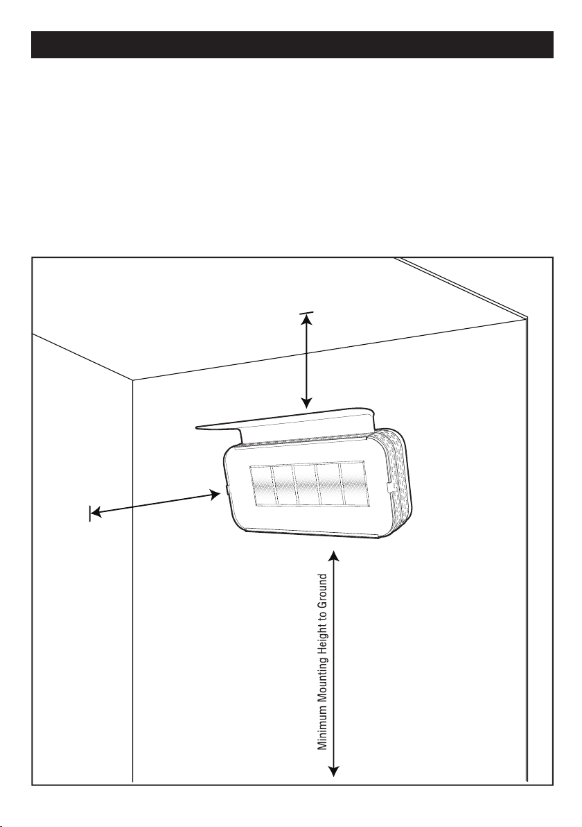
3. Proper clearance from combustible materials must
be maintained at all times. The minimum clearances
are as follows:
Minimum Clearance from Combustibles:
Side 1000 mm Bottom 2000 mm
Ceiling 400 mm
Combustible materials are considered to be wood,
compressed paper, plant fibres, plastic, plexiglas or
other materials capable of being ignited and burned.
Such materials shall be considered combustible even
though flame proofed, fire-retardant treated or plastered.
Additional clearance may be required for glass, painted
surfaces and other materials which may be damaged by
radiant or convection heat.
Gas Requirements:
Solaris LPG Models
1. Use Propane (LPG) gas only.
2 The approved inlet pressure to the appliance is
2.75KPA.
To convert the product to (LPG), call the Sitro service
team for injector, hose and regulator requirements.
Note! Heater must be installed and serviced by a
licenced gas fitter or plumber
Solaris Natural Gas Models
1. Use Natural Gas Only.
2 Always use Natural Gas Regulator (supplied).
3. Ensure that inlet pressure to the regulator does not
exceed 5KPA.
4. The approved inlet pressure to the appliance is
1.0KPA (RH205) / 0.8KPA (RH200).
3
Page 4
PRODUCT OVERVIEW
1. The hose must be protected from contact with
hot or sharp surfaces both during use and while
in storage. The hose assembly should be visually
inspected prior to each use of the appliance. If
excessive abrasion or wear is evident, or the hose
is cut, it must be replaced prior to operating the
appliance. The replacement hose assembly may be
obtained from the manufacturer.
2. DO NOT use any pressure regulator or hose
assembly other than those supplied with the
appliance. Replacement pressure regulator
and hose assembly must be those specified.
Replacement parts maybe obtained from the
manufacturer or your local sales
representative.
3. Installation and use of this appliance must conform
with local codes and AS/NZS 5601.
IMPORTANT
Storage of an appliance indoors with the cylinder
attached is only permitted if the size of the cylinder
complies with AS/NZS 1596; otherwise cylinders
must be stored outdoors in a well ventilated area.
The guards are fitted to this appliance to reduce the
risk of fire or injury from burns and no part of it should
be removed.
This appliance must be protected from exposure to
rain and wind.
LPG GUIDELINES
If the product has been converted to LPG, then you
must ensure the following conditions:
1. This appliance is designed to operate with a
standard 9kg propane cylinder with Approved
Cylinder Connection.
2. The valve outlet must be maintained in good
condition. When the cylinder is not in use, be sure
to cover it with a dust cap. A leak test should be
performed with soapy water whenever connecting a
new cylinder. NEVER use a match to test for leaks.
3. The propane cylinder must be turned off whenever
the appliance is not in use. When the appliance is
to be stored indoors, the propane cylinder and the
appliance must be disconnected and the cylinder
stored in accordance with the Standard for Storage
and Handling of Liquefied Gases.
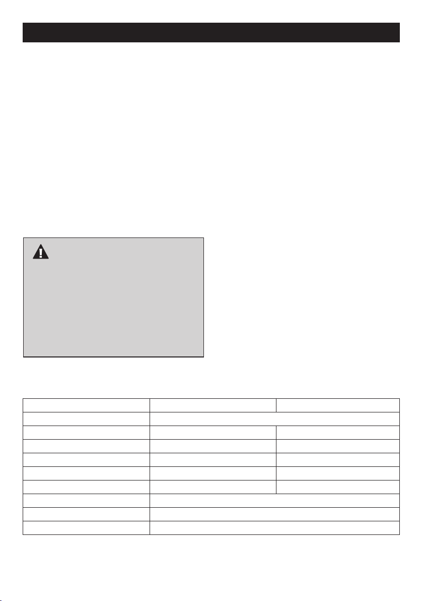
SPECIFICATIONS
Gas type LPG NATURAL GAS
Manufactured by Gasmate
AGA Approval No.
Gas Consumption 35 MJ/h 35 MJ/h
Gas Type Propane Gas (LPG) Only Natural Gas
Gas Pressure 2.75 KPA 1 KPA (RH205), 0.8KPA (RH200)
Injector Size 1.6mm 2.80mm (RH205), 2.85mm (RH200)
Weight RH200 - 15Kg RH205 - 14Kg
Voltageq 200-240V AC 50HZ
Current >1 Amp
Note: If the appliance cannot be adjusted to perform correctly it should not be used until serviced or repaired.
Heater specifications can be found on the data label.
4
Page 5

INSTALLATION AND SERVICING
ESSENTIAL INFORMATION
The warranty to the product will be voided if any
component of the patio heater is tampered with, or
altered.
To have these units altered or serviced by an
unauthorised person may render the product inefficient,
and at worst dangerous.
SERVICING INSTRUCTIONS
Appliances should be serviced at least annually and
servicing must only be carried out by a Licensed
Plumber or Authorised Person.
1. Remove Guard from Burner Housing.
2. Clean the Burner Ports and top with a Soft Brush.
Inspect and clean all combustion air inlets.
3. Clean thermocouple tip and spark igniter using a
soft wire brush.
4. Check operation of the igniter and the
thermocouple. Should new parts be required
contact the Supplier or Sitro Group Australia.
INSTALLATION FOR WALL MOUNTED
Natural Gas Heaters must be installed by an Authorised
Person.
Brackets for suspended installation must be permanently
fixed to a solid structure.
Positioning of both floor mounted and suspended
heaters must maintain required clearances.
i.e. 1000mm above, 1000mm on all sides and 500mm
below the heater emitter mesh.
It is a Standards Australia requirement that an approved
metal tube such as copper or galvanized steel or an
AGA certified stainless steel braided hose assembly be
utilised to convey gas to the burner head, and must be
installed by an authorised person, i.e. licensed plumber.
A Natural Gas Patio Heater is not designed for relocation
to varying locations, so the most preferable permanent
location should be selected prior to installation.
TO BE INSTALLED ONLY BY AN AUTHORISED PERSON
HEATER ASSEMBLY
NOTE: Recommended clearances must be
maintained.
* Remove transit protection material.
TOOLS REQUIRED: Drill
Masonry drill bit
Adjustable spanner
Phillips head screwdriver
STEP 1.
Firmly attach the mounting bracket using expanding
fasteners to a solid wall or alternatively speak with your
hardware supplier.
STEP 2.
Attach the natural gas regulator between the manual
shut off valve of the supply line and the heater gas hose
or pipe and set the outlet pressure at 1kPa.
GAS PIPING
1. Where it is not practical to install solid tube an
AGA certified stainless steel braided hose can be
installed. This hose assembly must comply with AS/
NZS 5601. Gas Installations, pipe sizing tables and
shall not exceed 3 metres in length. The internal
diameter of the hose must not be less than 15mm.
2. Check with local and state plumbing and heating
codes regarding sizing of the gas lines.
3. All gas pipe connections to the heater(s) must
be sealed with a gas pipe compound resistant to
Natural Gas.
4. Installation of a drip leg if required in the gas supply
line going to each heater must conform to AS/NZS
5601.
5. When checking for gas leaks, do no use an open
flame. Use a soap and water solution and check for
bubbles indicating gas leakage (refer Page 6).
6. Installation of 1/8” NPT plugged tapping, accessible
for test gauge connections, is required upstream of
the gas supply connection to the heater.
5
Page 6
400mm
2000mm
1000mm
INSTALLATION AND SERVICING
RADIANT CERAMIC HEATER
Minimum Clearances from Combustible
Surfaces*:
Care should be taken to ensure that the heater is not
installed:
• Where heat/ignition can cause damage to gas
cylinders lines
• Near other combustible materials
• In open locations subject to rain
• In indoor residential locations
• In areas without sufficient clearances (refer below)
IMPORTANT
This appliance must only be used in a well ventilated
area. *Combustible materials are considered to be wood,
compressed paper, plant fibres, plastic or other materials
that are capable of being ignited and burned.
Refer Page 15 for safe appliance locations
6
Page 7
INSTALLATION AND SERVICING
LEAK TESTING THE PRODUCT
A gas leak test must be done after assembly and before
operating the appliance. Procedure as follows:
1. If the product is installed on Natural Gas, the hose &
regulator must be connected to both the heater and
mains supply. If the product is installed on LPG then
the hose & regulator must be connected to both the
heater and a full gas cylinder.
IMPORTANT
Any threaded connection that is required in the
assembly of the hose & regulator must be tightened
with a shifter or spanner. Failing to do this may lead
to a gas leak at the connection.
2. Must ensure the unit is not running when leak test is
being performed
RH200 (Auto): Power must be switched off
RH205 (Manual): Do not light the unit
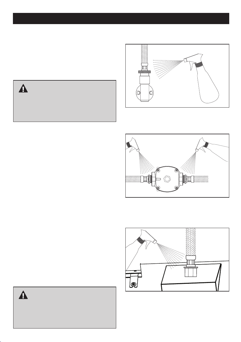
3. Make a mild soapy water solution. Apply with a
spray bottle, soft cloth or brush to the following
connections:
Hose connection to mains supply if on
natural gas (See image 1) or if on LPG, it
is the regulator connection to gas cylinder
Hose connection to regulator (See image 2)
Hose connection to the heater (See image 3)
4. Turn on the gas supply either at the mains or gas
cylinder
5. Apply the soapy water solution to the 3 connections
6. If soap bubbles appear at any of the connections,
there is a gas leak
7. If a gas leak is detected, turn the gas supply off.
Tighten any leaking fittings and repeat the process
8. If soap bubbles still appear (gas is still leaking), you
must:
If on natural gas, turn off the gas supply at the
mains then contact the licenced gas installer
If on LPG, turn off the gas supply at the
cylinder and disconnect the regulator, then
contact the licenced gas installer
IMAGE 1
IMAGE 2
IMAGE 3
IMPORTANT
It is the responsibility of the gas installer to ensure
there are no leaks when installing the product. DO
NOT contact the place of purchase or supplier, you
must contact the licenced gas installer.
7
Page 8
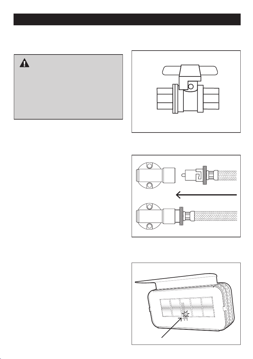
RH200 SOLARIS DELUXE HEATER – OPERATING INSTRUCTIONS
START - TURNING THE HEATER ON
1. Before operating this appliance:
IMPORTANT
It is imperative that you ensure that the gas
installation and power installation has been
carried out in accordance with the manufacturers
guidelines in this instruction manual. A certificate
of compliance should be provided by the licenced
installer at the completion of any installation.
Make sure you read the instruction manual
thoroughly prior to use.
If there is any uncertainty in relation to the guidelines
stated in this instruction manual or to obtain a copy,
please call the Sitro Service Team on 1300 174 876
(Mon – Fri) 8.00am – 5.00pm or Email
[email protected] for technical support.
2. Turn the gas supply on:
- If the heater is connected to a ball valve
socket containing an on/off tap, then turn the
gas on at the tap. See image 1
- If the heater is connected to a bayonet point
then you can move straight to step 3, as the
gas is already flowing to the unit. See image 2
3. Ensure the appropriate gas pressure is set:
Refer to page 2 of the instruction manual under the
heading Gas Requirements.
IMAGE 1
IMAGE 2
4. Turn the power on at the power point.
5. Automatic Ignition: Once the power is turned on and
gas is flowing to the unit, it should automatically
begin to ignite the heater. Visually you should see
a spark at the base of the centre tile, which will
eventually ignite the gas and light the tiles. See
image 3
- Once the heater is lit the tiles will start to
glow orange giving indication that the unit is
fully functional.
IMAGE 3
Ignition Spark
8
Page 9

RH200 SOLARIS DELUXE HEATER – OPERATING INSTRUCTIONS
6. Ignition Failure: If the heater fails to ignite, then turn
the power off at the power point.
- Wait 10 seconds, then turn the power back on
at the power point. If the heater fails to
ignite after 6 attempts, refer to the troubleshooting
guide in the back of the instruction manual for
further guidance or alternatively contact the Sitro
Service Team on 1300 174 876 (Mon – Fri)
8.00am – 5.00pm or Email
[email protected] for technical support.
STOP - TURNING THE HEATER OFF
1. Turning the unit off temporarily: To turn the heater off
temporarily, simply turn the power off at the power
point leaving the gas supply on.
2. Turning the unit off permanently: Firstly, turn the
power off at the power point and secondly shut the
gas off at the gas supply.
- If the heater is connected to a ball valve socket
containing an on/off tap, then simply turn the gas
off at the tap.
- If the heater is connected to a bayonet point,
then the hose will need to be disconnected from
the bayonet socket to shut the gas off.
Note:
The heater must be completely shut off for 10 minutes
before being relighted. This allows for any excess gas to
dissipate and for the unit to cool down.
IMPORTANT
Popping Noise:
When turning the heater on and off, there will be
a slight popping noise which is normal when the
burner is ignited or extinguished. If, however a
popping noise occurs when the unit is running,
turn off the heater at the power and gas supply
and contact the Sitro Service Team for further
advice.
Smoke & Odour:
Fumes will be emitted from the heater upon first
use which is smoke and odour from oil from
manufacturing being burnt. Important to avoid
inhaling the fumes. Generally, odour and smoke
will dissipate after approx. 20-30 minutes.
Wind Protection:
Important to protect the heater from wind while
attempting to light.
9
Page 10
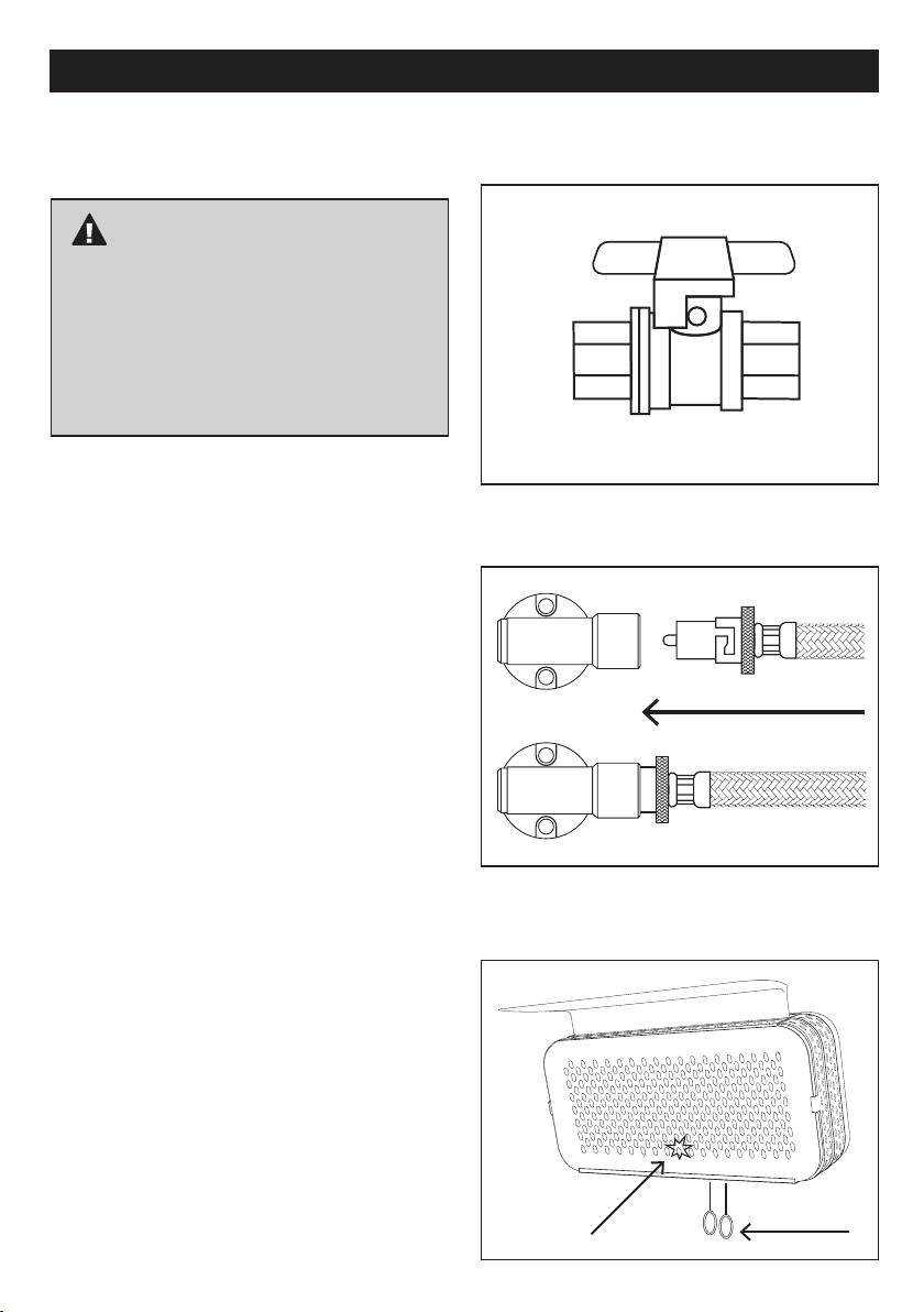
RH205 SOLARIS HEATER – OPERATING INSTRUCTIONS
START - TURNING THE HEATER ON
1. Before starting this appliance:
IMPORTANT
It is imperative that you ensure that the gas
installation and power installation has been
carried out in accordance with the manufacturers
guidelines in this instruction manual. A certificate
of compliance should be provided by the licenced
installer at the completion of any installation.
Make sure you read the instruction manual
thoroughly prior to use.
If there is any uncertainty in relation to the guidelines
stated in this instruction manual or to obtain a copy,
please call the Sitro Service Team on 1300 174 876
(Mon – Fri) 8.00am – 5.00pm or Email service.group@
sitro.com.au for technical support.
2. Turn the gas supply on:
- If the heater is connected to a ball valve
socket containing an on/off tap, then turn the
gas on at the tap. See image 1
- If the heater is connected to a bayonet point
then you can move straight to step 3, as the
gas is already flowing to the unit. See image 2
3. Ensure the appropriate gas pressure is set:
Refer to page 2 of the instruction manual under the
heading Gas Requirements.
IMAGE 1
IMAGE 2
4. Igniting the unit: Pull and hold down the ignition
cord on right and maintain tension for approx. 10
seconds to ignite the tiles. Maintain the hold for a
further 15 seconds to heat the thermocouple, then
release the ignition cord.
Note:
Visually you should see a spark at the base of the
centre tile when holding down the ignition cord.
IMAGE 3
10
Ignition Spark
Ignition Cord
Pull Down
Page 11
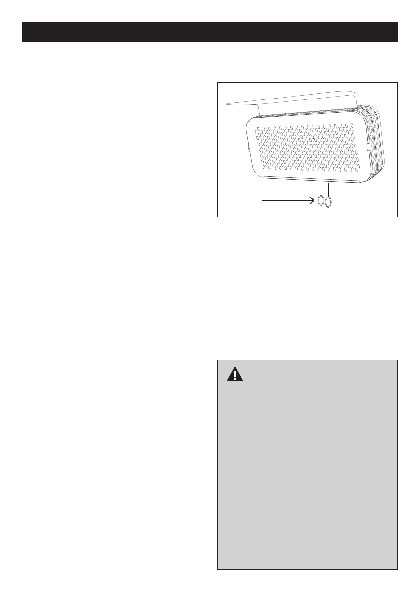
RH205 SOLARIS HEATER – OPERATING INSTRUCTIONS
6. Ignition Failure: If the heater fails to ignite after 6
attempts, refer to the troubleshooting guide in the
back of the instruction manual for further guidance
or alternatively contact the Sitro Service Team on
1300 174 876 (Mon – Fri) 8.00am – 5.00pm or Email
[email protected] for technical support.
STOP - TURNING THE HEATER OFF
1. Turning the heater off temporarily: Pull down the
shut off cord on left by giving it a quick tug and
release. See image 4.
- Once the heater is turned off the tiles will no
longer be glowing orange giving indication that the
unit is now off.
2. Turning the heater off permanently: Firstly, follow
step 1 and secondly shut the gas off at the gas
supply.
- If the heater is connected to a ball valve socket
containing an on/off tap, then simply turn the gas
off at the tap.
- If the heater is connected to a bayonet point,
then the hose will need to be disconnected from
the bayonet socket to shut the gas off.
Note:
The heater must be completely shut off for 10
minutes before being relighted. This allows for any
excess gas to dissipate and for the unit to cool
down.
IMAGE 4
Shut Off Cord
Pull Down
3. Failure to shut down unit: If the tiles continue to
glow orange it means the unit is still functioning. If
this occurs, repeat step 1.
- If the problem persists, shut off the gas supply
and call the your Licenced Gas Installer for further
instruction.
IMPORTANT
Popping Noise:
When turning the heater on and off, there will be
a slight popping noise which is normal when the
burner is ignited or extinguished. If, however a
popping noise occurs when the unit is running,
turn off the heater at the power and gas supply
and contact the Sitro Service Team for further
advice.
Smoke & Odour:
Fumes will be emitted from the heater upon first
use which is smoke and odour from oil from
manufacturing being burnt. Important to avoid
inhaling the fumes. Generally, odour and smoke
will dissipate after approx. 20-30 minutes.
Wind Protection:
Important to protect the heater from wind while
attempting to light.
11
Page 12
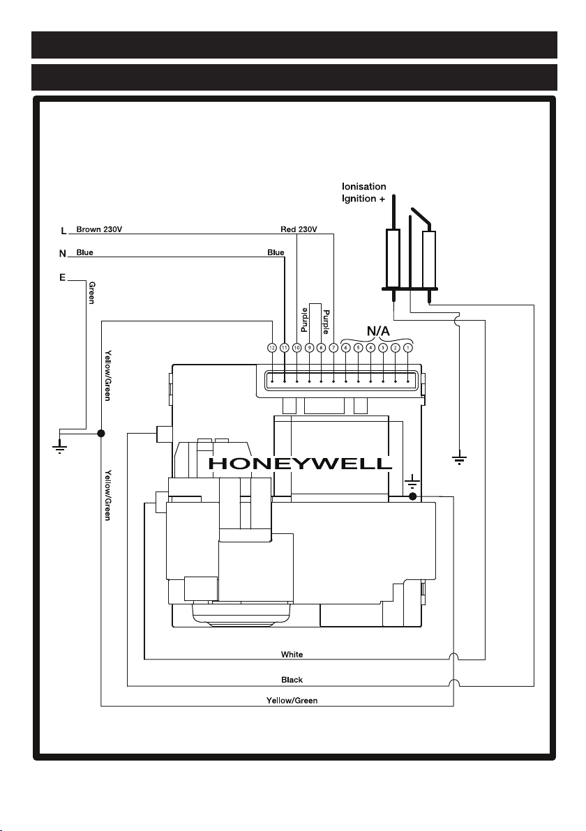
RH200 SOLARIS DELUXE AUTO ELECTRICAL DIAGRAM
WIRING DIAGRAM - HONEYWELL CONTROL, HONEYWELL GAS VALVE
ELECTRICAL DIAGRAM
NOTE: THIS DIAGRAM IS SPECIFICALLY FOR THE RH200
AND IS NOT APPLICABLE FOR THE RH205
12
Page 13
OPERATION DATA -
HONEYWELL CONTROL BOX
The following operation sequence is valid only where the
components are installed according to the manufactures
assembly and installation instructions. Please do not
modify the wiring configuration, gas train or any other part
of the heater assembly.
Application
The Honeywell electronic gas burner control system is
suitable for atmospheric gas burners for non-permanent
operation.
Although the Honeywell unit is available non volatile
lockout, its configuration in the Solaris RH200 Deluxe
Heater limits it to volatile lockout, i.e. the restart from this
condition is possible by the interruption and subsequent
restoration of the mains power supply.
Features:
• Compliance with AGA standard for automatic gas
burner flame monitoring and control systems
• Compliance with EN 298 (European standard for
automatic gas burner flame monitoring and control
systems)
• Compliance with AGA (Australian standard for
automatic gas burner flame monitoring and control
systems)
• Flame monitoring based on rectification property of
the flame (ionisation)
TECHNICAL DATA
Supply voltage 220~240V AC 50Hz
Operating temperature -20°C +60°C
Ambient humidity 90%max at 40°C
Protection degree IPX4
Timings:
Self Check time 1.5 s
Safety time (TS) 25 s
Drop out time on running flame failure 1 s
Power consumption, at start up 10VA
Power Consumption, Running 4VA
Ignition
Ignition Voltage 15kV with 40pF load
Spark repetition rate 33 Hz
Max. Cable length 1M
Recommended spark gap 0.14”
Consumption 2,5 VA
Spark energy 3 uAs
Directions for use
• Automatic controls are safety devices and shall not
be opened. The manufacturer’s responsibility and
guarantee are invalid if the control is unduly opened.
• A regulation shutdown must occur every 24hours to
enable the unit to check its own efficiency (systems
for non permanent operation)
• Connect and disconnect the unit only after switching
off the power supply
• Avoid exposing the unit to dripping water
• Ventilation and the lowest temperature ensures the
longest life of the control Electrical Installation
• Live and Neutral should be connected correctly; a
mistake could cause a dangerous situation.
• Before starting the system check cables carefully for
incorrect installation
• The earth terminal of the control, the metal frame of
the burner and the earth on the mains supply must
be well connected
Operation
At every start, the control unit proceeds to a self-checking
of its own components. During the pre-purge or waiting
time (TW) the internal circuit makes a test of the flame
signal amplifier. Extraneous light or fault in the amplifier
will result in the simulation of a flame which will prevent
the control from starting.
At the end of the waiting or pre-purge time, the gas valve
is energised and the ignition device is operated. In this
way, the safety time (TS) begins.
If a flame is detected during the safety time, the ignition
device is inhibited and the gas valve remains energised.
If the control does not detect any flame signal during
the safety time, at the end of safety time (TS), the unit
proceeds to lockout and the gas valve and ignition device
are switched off.
If the established flame signal is lost, (during the safety
time or during operation thereafter) this will cause the
ignition device to be reactivated within 1 second.
If the burner does not light within 25 seconds of ignition
reactivation, the heater will enter failure lockout mode and
must be reset.
13
Page 14
RH200 SOLARIS DELUXE AUTO ELECTRICAL DIAGRAM
OPERATION DATA - HONEYWELL VALVE
The VK series gas control have been specially developed
for application in domestic appliances. The Honeywell
Gas Valve is a multi-functional control which incorporates
an adjustable direct acting pressure regulator. It is
designed for operation on 220~240V AC 50Hz.
Standard Specifications
• 3/8” SAE Male Thread connection.
• Ambient Temperature Range of 0°C to 60°C.
• Compact Size: 86.5mm x 63.5mm x 65.9mm.
• 50mb Pressure Rating.
• 3/8” x 3/8” SAE Inlet and Outlet.
• Earthing terminal – 6mm spade tab.
• Tamper resistant screws.
• Top mounted coils that can be field replaced.
TECHNICAL DATA
Max inlet working pressure 50 mbar
Installation group Group 2
Operating Temperature 0°C to 60°C
Voltage Ratings 220~240V AC 50Hz
0.52A
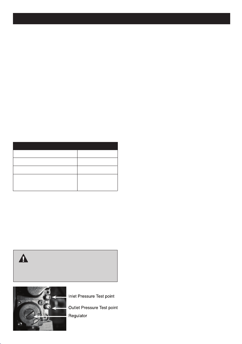
Adjust Regulator Pressure
• Unscrew the regulator cover.
• Unscrew the outlet plug to measure the outlet
regulator pressure by using manometer.
• Adjust the pressure by turning the regulator screw
clockwise or anti wise.
• Adjust the pressure according to appliance
specification.
IMPORTANT
Remember to place the regulator cover, outlet and
inlet back on.
14
Page 15
SAFE APPLIANCE LOCATIONS
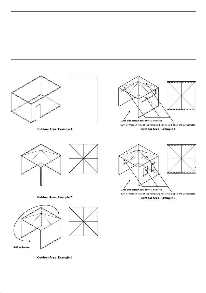
This appliance shall only be used in an above ground open-air situation with natural ventilation, without stagnant areas, where gas leakage and products of
combustion are rapidly dispersed by wind and natural convection.
Any enclosure in which the appliance is used shall comply with the following:
An enclosure with walls on all sides, but at least one permanent opening at ground level and no overhead cover (see Example 1).
Within a partial enclosure that includes an overhead cover and no more than two walls (see Example 2 & 3).
Within a partial enclosure that includes an overhead cover and more than two walls, the following will apply:
At least 25% of the total wall area is completely open, and
at least 30% of the remaining wall area is open and unrestricted.
In the case of balconies, at least 20% of the total wall area shall be and remain open and unrestricted (see Example 4 & 5).
The following figures are diagrammatic representations of outdoor areas. Rectangular areas have been used in these figures – the same principles apply to any
other shaped area.
15
Page 16
TROUBLESHOOTING, CLEANING AND MAINTENANCE
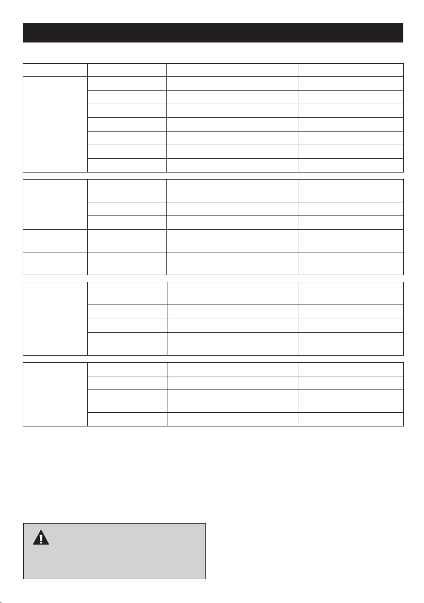
TROUBLE SHOOTING
Fault Causes Remedy Action
Main burner (Tiles)
will not light
(a). Air in gas line Purge gas line Contact Licenced Gas Installer
(b). Blockage in gas line Trace back and clear Contact Licenced Gas Installer
(c). Igniter not sparking Repair lead, electrode, piezo or replace Contact Licenced Gas Installer
(d). Cylinder turned off Turn on Customer - (Owner of Heater)
(e). Cylinder empty Install full cylinder Customer - (Owner of Heater)
(f). No Power Check power supply by authorised Electrician Contact Authorised Electrician
(g). No Gas Check gas supply by authorised Plumber Contact Licenced Gas Installer
Main burner (Tiles)
will not light fully
Main burner (Tiles)
cut out
Low heat output (a). Restricted gas flow Trace back to source, clear where necessary Contact Licenced Gas Installer
(a). Poor gas supply Trace supply back to source, clear when
(b). Gas control inoperative Inspect valve, rectify Contact Licenced Gas Installer
(c). Insufficient gas Inspect tile/s & replace Contact Licenced Gas Installer
(d). Partial blockage in
gas line
(e). Insufficient gas Rectify gas supply / install full cylinder Licenced Gas Installer / Customer -
(a). (RH205 Only) - Faulty
thermocouple
(b). Poor gas supply Trace back to source, clear where necessary Contact Licenced Gas Installer
(c). Faulty gas valve Replace gas valve Contact Licenced Gas Installer
(d). Check burner ports for
blockage
(b). Faulty regulator Check regulator setting and replace if faulty Contact Licenced Gas Installer
(c). Regulator pressure
setting incorrect
(d). Faulty gas valve Replace gas valve Contact Licenced Gas Installer
necessary
Trace back and clear Contact Licenced Gas Installer
Replace / tighten thermocouple Contact Licenced Gas Installer
Clean if necessary
Check regulator setting and replace if faulty Contact Licenced Gas Installer
Contact Licenced Gas Installer
(Owner of Heater)
CLEANING AND MAINTENANCE: Proper care and
maintenance will keep your appliance in operating
condition and prolong its life.
IMPORTANT
CAUTION: Be sure your appliance is off and cool
before cleaning.
CLEANING EXTERIOR SURFACES
1. Clean with a wash cloth or sponge using a mild soap
and warm water solution. Note – Never use abrasive
cleaners of any type on your heater. These will scratch
surfaces during the cleaning process.
2. Ensure the appliance is dried after cleaning. It is
recommended the appliance be operated after cleaning
to ensure the appliance is dry.
16
Page 17
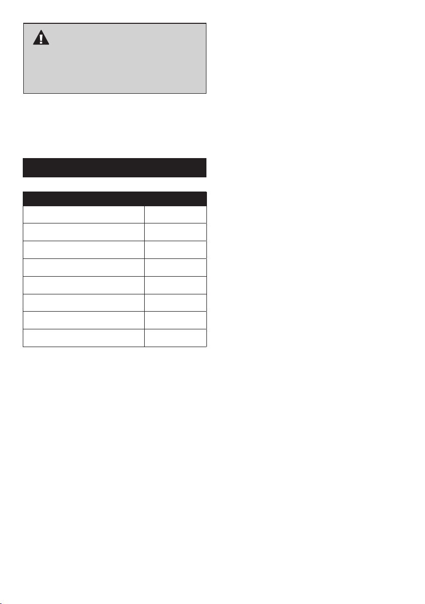
IMPORTANT
The following parts must be installed by a licenced
installer. Failure to follow this direction can be
dangerous and will void the warranty!
RH200 SOLARIS PARTS LIST
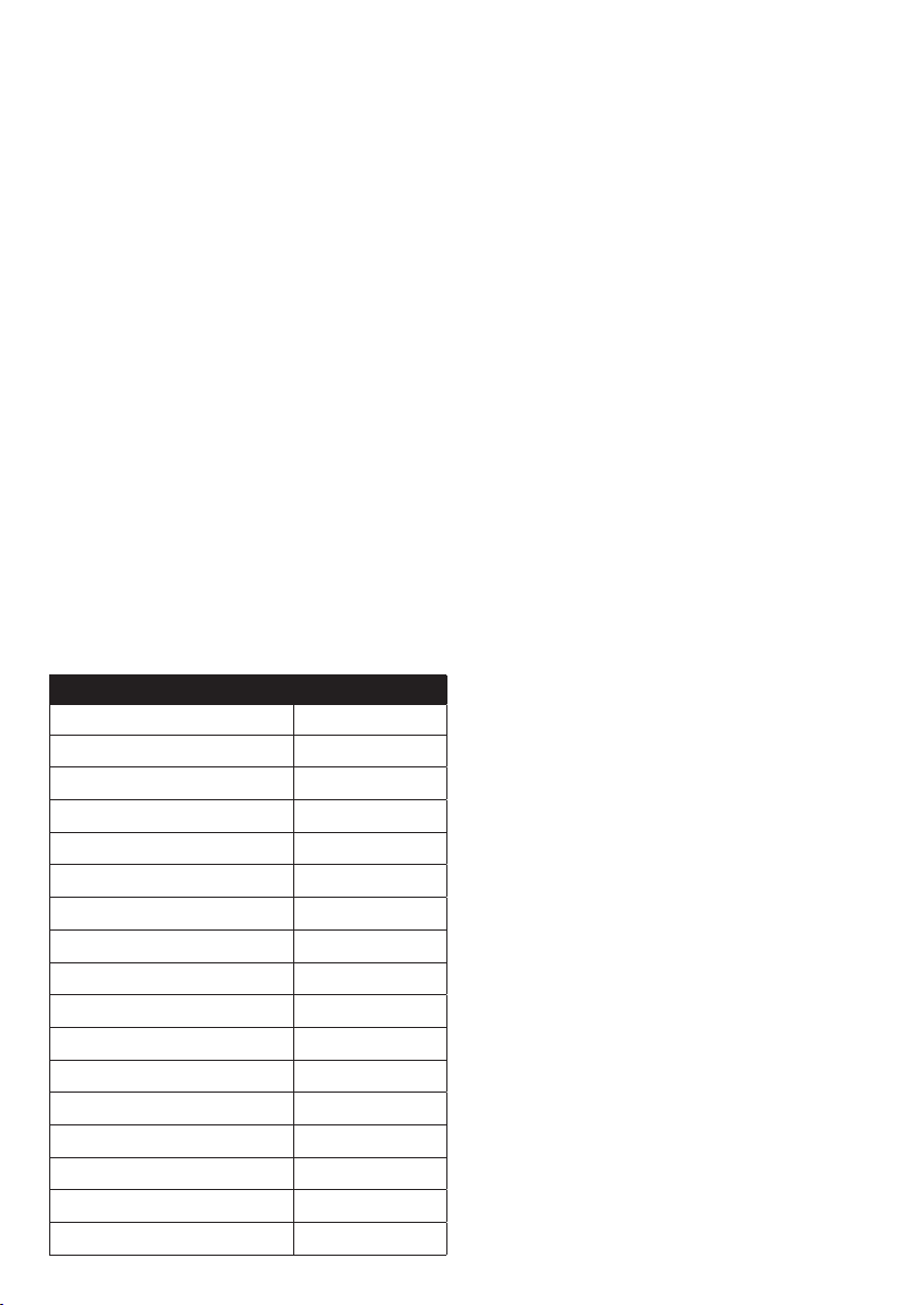
DESCRIPTION PART#
Ceramic Tile Assembly 91 RH200CTA
Ion Sensor 91 RH200IS
Natural Gas Injector 91 RH200INJ
Auto Gas Valve & PCB 91 RH200AGVPCB
Propane Injector for Converting to LPG 91 RH200PINJ
Ceramic Tile Assembly 91 RH200CTA
Short Flexible Hose 91 RH200SFH
Reflector 91 RH200R
To order parts please contact our service team on 1300
174 876 or email [email protected]. The service
team are available between 8.00am – 5.00pm (Mon – Fri).
17
Page 18
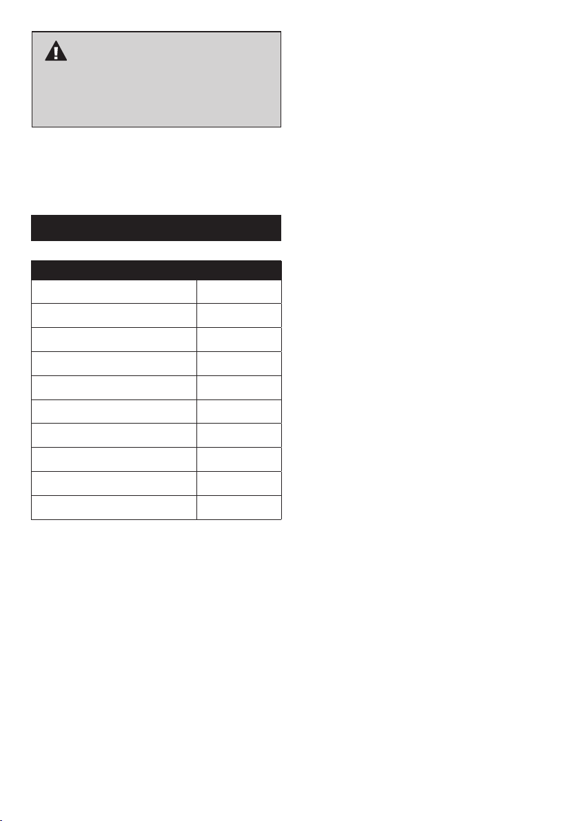
IMPORTANT
The following parts must be installed by a licenced
installer. Failure to follow this direction can be
dangerous and will void the warranty!
RH205 SOLARIS PARTS LIST
DESCRIPTION PART#
Ceramic Tile Assembly 91 RH200CTA
Natural Gas Injector 91 RH200INJ
Propane Injector for Converting to LPG 91 RH200PINJ
On/Off Cord 91 RH205OC
Gas Valve 91 RH205GV
Thermocouple 91 RH205TCW
Electronic Ignition 91 RH205EI
Ignition Lever 91 RH205IL
V/E Guard 91 RH205VEG
Reflector 91 RH200R
To order parts please contact our service team on 1300
174 876 or email [email protected]. The service
team are available between 8.00am – 5.00pm (Mon – Fri).
18
Page 19

NOTES
19
Page 20

For any queries or assistance call
Customer Service
(Australia Only)
1300 174 876
Hours of operation:
Monday to Friday 8am - 5pm EST
Do not return to place of purchase.
Keep your purchase receipt, this will be required to
make any claims under the 12 month warranty.
20
 Loading...