

Page 1
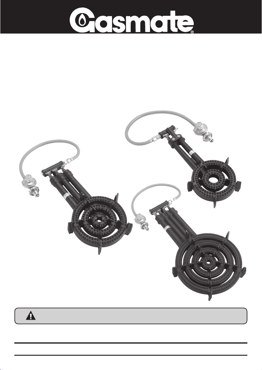
Ring Burner Series
FEATURES
• Ideal for camping
• Suitable for cooking at home where larger ports
and a higher heat output is required – Convenient
for cooking sauces, crabs, lobster or any shell fish
• Made from high quality cast iron with
brass controls
• Outlet: ¼” BSP thread
• Hose and Regulator included
• Propane use only
• AGA certified
RB2
RB3
RB4
NOTE: ONLY USE ON A NON-COMBUSTIBLE SURFACE
Gasmate® is a registered trademark of: Sitro Group Australia Pty Ltd www.sitro.com.au
Aber, Hamilton, N.Z www.gasmate.co.nz
Important: Retain these instructions for future use.
02562 03/11
Page 2
GENERAL INFORMATION
Gas Installation Codes
• Appliance must be used in accordance with the
installation requirements of your gas supply
authority, or the appropriate installation code
issued by Standards Australia AS 5601.
• Appliances for use with bottled gas are labelled
‘propane gas’.
• Only use on a non-combustible surface.
Clearances
Minimum Clearances from combustible materials
must be: Cylinder - 500mm. Wall - 500mm.
Above - 1200mm.
Below - never use on a flammable surface. Only use
on a non-combustible surface.
Hose & Regulator Safety
The regulator and hose assembly supplied with the
appliance are suitable for propane gas only.
The pressure regulator and hose assembly supplied
with the appliance must be used. Replacement
pressure regulators and hose assemblies must be
those specied by the appliance manufacturer.
Only use the hose assembly supplied with this
appliance for direct connection to the cylinder
“DO NOT USE ADAPTORS”.
Check the regulator “O” Ring periodically for
wear or damage and replace if required.
When connecting the hose and regulator assembly
to the gas cylinder, take care to avoid unnecessary
twisting or kinking of the exible hose. Maximum
hose length is 1 metre.
After the assembly has been secured, turn on the
gas and check for leaks by brushing a soap and
water solution overall connections.
DO NOT USE this appliance if it is leaking, damaged
or does not operate properly.
If you are unable to correct the leak by tightening
the connections, turn off the gas and contact the
supplier immediately.
Always ensure the appliance is kept away from
ammable materials and the gas cylinder clear
of any heat source. When changing over from an
empty gas cylinder to a full one make sure this
procedure is carried out in a well ventilated location,
preferably outside, away from people and away from
any sources of ignition; such as naked ames, pilot
ames, electric heaters/equipment.
Specifications
Appliance specifications can be found on the data
label attached to the appliance body.
Gas Cylinder Use & Safety
This is a low pressure appliance and must only be
used with the hose and regulator supplied. This
appliance shall only be used with propane gas
cylinders certified to AS 2469. It may be hazardous
to attempt to fit other types of gas containers.
The gas cylinder should be lled by a reputable gas
supplier and visually inspected and re-qualied at
each lling.
Always keep cylinder in an upright position. Always
close the cylinder valve when the appliance is not in
use.
Do not subject gas cylinder to excessive heat.
IMPORTANT
• Outdoor use only
• Read these instructions for use carefully.
Familiarise yourself with the appliance
before connecting it to its gas container.
Keep these instructions for future
reference.
• Failure to comply with these instructions could
result in a re or explosion which could cause
serious bodily injury, death or property
damage.
CAUTION: Accessible parts may be very hot.
• Keep young children away.
• DO NOT modify this appliance.
• DO NOT move this appliance during use.
• Turn off the gas supply at the gas cylinder
after use.
• Parts sealed by the manufacturer or their
agent must not be manipulated by the user
• This appliance is only to be used outdoors.
• Never operate this appliance without a
regulator.
• Do not test for gas leaks with an open ame.
• If this information is not followed exactly a re
causing death or serious injury may occur.
• Do not store a spare gas cylinder under or
near this appliance. Never ll the cylinder
beyond 80% full. This appliance is only to be
used and stored outdoors.
• If there is a leak on your appliance (smell
of gas), immediately attempt to turn off the
cylinder valve. Remove the appliance to a
well ventilated location away from any ignition
source. Only check for leaks outdoors using
soapy water. DO NOT try to detect leaks using
a ame.
• Never connect an unregulated gas cylinder to
your appliance.
NOTE: ONLY USE ON A
NON-COMBUSTIBLE SURFACE
2
Page 3
Never Store your Gas Cylinder Indoors.
If you store your appliance indoors, ALWAYS
disconnect the gas cylinder rst and store the
cylinder safely outside. Cylinders must be stored
outdoors in a well ventilated area out of reach of
children, and must not be stored in a building,
garage or any other enclosed area.
Gas connection is 1/4” BSP
Location of your Appliance
Only use on a non-combustible surface. DO NOT
use your appliance in garages, porches, sheds,
breezeways, or other enclosed areas. Your appliance
is to be used OUTDOORS ONLY. The appliance is not
intended to be installed in or on recreational vehicles
and/or boats and should not be placed on any
surface that will burn. Do not obstruct the ow of
combustion and ventilation air around the appliance.
Protect Children
Keep children away from appliance during use and
until appliance has cooled after you have nished.
Do not allow children to operate appliance.
Always ensure that no sporting or physical activities
are carried out in close proximity to the appliance
during use and while still hot.
Tools You Will Need
Adjustable spanner, phillips screwdriver.
Check Appliance for any Damage
Inspect appliance parts as you proceed. Contact
your supplier for assistance regarding replacement
of any damaged or missing parts. Do not assemble
or operate a appliance that appears damaged.
Appliance for use with gas cylinders are labelled
‘propane gas’. Check labelling at the gas connection
on your appliance.
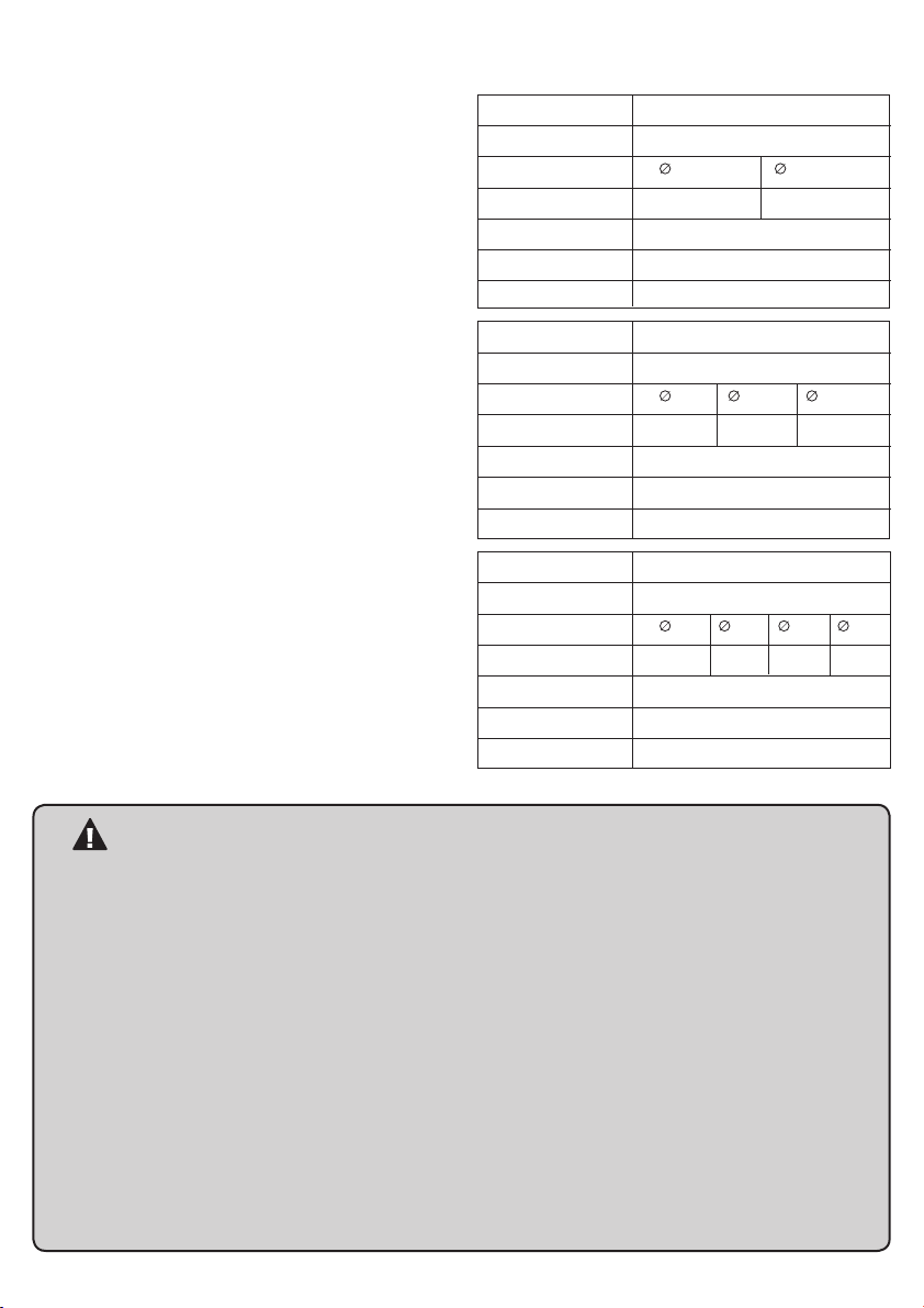
Product details:
RB2
Gas Type Propane
Inj. Size (mm)
Gas Cons. (MJ/h) 5.5 13
Gas Pressure 2.75kPa
Overall size 425 x 200 x 70mm
Weight 3.4kg
RB3
Gas Type Propane
Inj. Size (mm)
Gas Cons. MJ/h 1.6 8.5 15.5
Gas Pressure 2.75kPa
Overall size 465 x 239 x 90mm
Weight 5.9kg
RB4
Gas Type Propane
Inj. Size (mm)
Gas Cons. MJ/h 3 8.5 15.5 27
Gas Pressure 2.75kPa
Overall size 640 x 355 x 112mm
Weight 13.1kg
0.7 1.10
0.4 0.9 1.20
0.5 0.9 1.2 1.5
FOR YOUR SAFETY
• Do not store or use petrol or other ammable
liquids in the vicinity of this or any other
appliance.
• Do not store empty or full spare gas cylinders
under or near this or any other appliance.
• Keep the gas hose away from hot surfaces and
protect from dripping grease. Avoid
unnecessary twisting of hose. Visually inspect
the hose prior to each use for cracks, excessive
wear or other damage. Replace the hose if
necessary.
• Never test for gas leaks with a lit match or
open ame.
• Never lean over cooking surface when lighting.
• Never alter or modify the regulator or gas
supply assembly.
• This appliance must not be used indoors.
• Only use in well ventilated areas.
• Carbon monoxide hazard - This appliance can
produce carbon monoxide which has no odour.
Using it in an enclosed space (for example:
caravan, tent, car, mobile home) may cause
death.
• This appliance shall only be used in an
above ground open-air situation with natural
ventilation, without stagnant areas, where
gas leakage and products of combustion
are rapidly dispersed by wind and natural
convection.
• Ensure the appliance is set up on a level and
stable surface.
• Do not move the appliance while in use or
when hot.
NOTE: ONLY USE ON A
NON-COMBUSTIBLE SURFACE
3
Page 4

RING BURNER COMPONENTS (Image as guide only)
1. Hose and Regulator assembly
2. Gas valve
• RB2 - screws on top
• RB3 - screws from underside
• RB4 - screws from underside
3. Burner
• RB2 - 2 rings
• RB3 - 3 rings
• RB4 - 4 rings
4. Trivets - to stand cooking pot on
Note: Remove any transit
protection material before using
the burner.
2
1
4
3
Venturi tube
BURNER ASSEMBLY
ASSEMBLY
Note: Remove any transit protection material before
using the burner.
1. Slide gas valve assembly into the burner
assembly and secure with the two screws
provided.
2. Attach the supplied hose and regulator to
the gas inlet.
GAS VALVE ASSEMBLY
Gas inlet
Gas valve in off position
Primary air disk
4
Page 5

GENERAL ASSEMBLY
Wall
Ground - Non combustible surface and/or material.
min 500mm min 500mmmin 1200mm
Connecting & Disconnecting to Gas
Source
Familiarise yourself with the general information and
safety guidelines located at the front of this manual.
Check:
1. Gas cylinder is lled. A sloshing sound will be
heard when shaken.
2. The gas valve is in the ‘OFF’ position
Connecting
1. Ensure cylinder and gas valve is in its full
off position.
2. Check for any damage to either the cylinder
connection or the hose. NEVER attempt to use
damaged equipment.
3. When connecting the hose to the cylinder tighten
the nut to a positive stop by hand or spanner.
4. Open cylinder valve fully. If a leak can be heard
at either end of the hose turn cylinder off and
tighten joint. Wait 5 minutes before re-testing
and use a soapy water solution to check the
joint. If bubbles appear the connection will need
to be re-tightened.
General Positioning
1. Never place or position the ring burner on
combustible material. Only use on a
non-combustible surface.
2. Ensure the gas hose is straight and not knotted.
CARE & MAINTENANCE
As with all appliances, proper care and maintenance
will keep them in top operating condition and
prolong their life. Your new gas appliance is no
exception. By following these cleaning procedures
on a timely basis, your appliance will be kept clean
and working properly with minimum effort.
Spiders and small insects occasionally spin webs or
make nests in the burner tubes during warehousing
and transit. These webs can lead to a gas ow
obstruction which could result in a re in and around
the burner tubes. Cleaning with a soft brush before
use and at least every six months is recommended.
This type of re is known as ‘FLASH-BACK’ and can
cause serious damage to your appliance and create
an unsafe operating condition for the user. Although
an obstructed burner tube is not the only cause of
‘FLASH-BACK’ it is the most common cause and
frequent inspection and cleaning of the burner tubes
is necessary.
Flash-Back
If re occurs in and around the burner, immediately
turn off gas at its source and turn the burner control
to ‘OFF’, wait until the appliance has cooled, then
clean the burner tubes and burner ports.
Cleaning
After cooking, turn burner gas cylinder valve and
burner valve to ‘OFF’. Let the burner cool before
attempting to clean and store. After use brush
excess dust, dirt and debris from the burner
surface. Ensure all the burner ports are clean
and open before storing and re-using. Ensure the
bottoms of all cooking pots / pans are cleaned of
any dirt or discolouration after use.
IMPORTANT
Before connecting and disconnecting
appliance to gas source, make sure burner
controls are in ‘OFF’ position.
CAUTION: When the appliance is not in use,
the gas must be turned off at the cylinder.
Check that the seals between the appliance
and the gas cylinder are in place and in good
condition before connecting the gas cylinder.
Do not use this appliance if it has damaged or
worn seals.
• Beware of spiders and wasps.
Burner tube should be inspected and
cleaned periodically.
• This appliance must only be serviced by an
authorised person.
NOTE: ONLY USE ON A
NON-COMBUSTIBLE SURFACE
5
Page 6

LIGHTING PROCEDURE
RB2
4
1
Inner # 1
Outer # 4
RB3
4
2
1
Outer # 4
Inner # 1
1st Middle # 2
RB4
4
2
1
3
Outer # 4
1st Middle # 2
Inner # 1
2nd Middle # 3
Burner Operation &
Ignition System Check
1. Turn inner gas valve on.
2. Open gas valve and light immediately with long
BBQ match following sequence in step 3.
3. Light the burners in order:
Without pot.
RB2 RB3 RB4
Inner # 1 Inner # 1 Inner # 1
Outer # 4 1st Middle # 2 1st Middle # 2
Outer # 4 2nd Middle # 3
Outer # 4
All of these will need to be lit using a long
BBQ match.
With pot.
RB2 RB3 RB4
Outer # 4 Outer # 4 Outer # 4
Inner # 1 1st Middle # 2 2nd Middle # 3
Inner # 1 1st Middle # 2
Inner # 1
The outer ring #4 will need to be lit using a long
BBQ match, all other rings will cross light if lit in the
above sequence.
4. Once lit adjust the primary air disk to provide a
clean blue ame.
5. Place cooking pot onto ring burner.
Gas valve and burner ring matching.
Problem Possible Reason Solution
Burner will not ignite Valve on gas bottle closed. Open valve on gas bottle.
Control knob is closed. Turn knob to high when lighting.
Food is not cooking Burner has gone out. Check that the gas bottle is not
or is taking too long empty and re-ignite burner.
After Use
Turn the gas cylinder valve off and wait for the ame
to go out. Then turn the appliance gas valve off.
AERATION
To ensure the ame is clean and blue, that is NO
yellow tip to ame or sooting, adjust the primary
air disk. The primary air disk can be adjusted
clockwise/counter clockwise by hand. The ideal
positioning of the aeration disk when measured from
the venturi tube is;
RB2 - INNER # 1 - 2mm open
- OUTER # 4 - 3mm open
RB3 - INNER # 1 - 7mm open
- 1st MIDDLE# 2 - 7mm open
- OUTER # 4 - 3mm open
RB4 - ALL BURNER RINGS 3mm open
6
Page 7

OPERATING PROCEDURE
The gas valve can be adjusted from “OFF to “HIGH”
and this will affect the cooking time.
Primary Air Disk
Gas Valve “OFF”
Gas Valve “ON”
Gas Inlet
Gas valve “ON” max.
The gas lever is in a straight line with the gas valve
to the venturi tube.
Gas valve “OFF”
The gas lever is at right angles to the gas valve and
the venturi tube.
Spillage
Turn off the cylinder gas valve. Wait for the ame to
go out. Using heat proof gloves:
• Remove cooking pan.
• Blow liquid from burner ports.
• Tip burner upside down to drain spilled liquid.
• Once dry re-position.
• Follow lighting procedures to re-light burner and
continue cooking.
IMPORTANT
• Do not smoke when attempting to ignite
appliance.
• Always use protective gloves when handling
hot components.
• Do not smoke at any time when attempting
to ignite the appliance burners.
Caution:
Do not move the appliance while in operation.
• Do not leave the appliance unattended
when alight.
NOTE: ONLY USE ON A
NON-COMBUSTIBLE SURFACE
For any queries or assistance call
Customer Service
Australia Only
1300 174 876
Monday to Friday 8.30am - 5.30pm EST
Do not return to place of purchase.
Keep your purchase receipt, this will be required to make any claims under the
Hours of operation:
12 month warranty.
Page 8

SAFE APPLIANCE LOCATIONS
This appliance shall only be used in an above ground open-air situation with natural ventilation, without stagnant areas,
where gas leakage and products of combustion are rapidly dispersed by wind and natural convection.
Only use on a Non-combustible surface.
Any enclosure in which the appliance is used shall comply with the following:
An enclosure with walls on all sides, but at least one permanent opening at ground level and no overhead cover.
Within a partial enclosure that includes an overhead cover and no more than two walls.
Within a partial enclosure that includes an overhead cover and more than two walls, the following will apply:
at least 25% of the total wall area is completely open, and
at least 30% of the remaining wall area is open and unrestricted.
In the case of balconies, at least 20% of the total wall area shall be and remain open and unrestricted.
DIAGRAMMATICAL REPRESENTATIONS OF OUTDOOR AREAS
The following figures are diagrammatical representations of outdoor areas. Rectangular areas have been used in these figures
– the same principles apply to any other shaped area.
 Loading...