

Page 1

No. MDE-4813
Revision C
June 2011
CCFFNNPPLLUUS
S
INSTALLATION MANUAL
This document is based on Orpak’s Controller Unit (OrCU 3000)
installation manual P/N 817438032
Page 2

Page 3

SAFETY CONSIDERATIONS
Read all warning notes and instructions carefully. They are included to help you installing the Product safely
in the highly flammable environment of the fuel station. Disregarding these warning notes and instructions
could result in serious injury or property damage. It is the installer responsibility to install, operate and
maintain the equipment according to the instructions given in this manual, and to conform to all applicable
codes, regulations and safety measures. Failure to do so could void all warranties associated with this
equipment.
Remember that the fuel station environment is highly flammable and combustible. Therefore, make sure
that actual installation is performed by experienced personnel, licensed to perform work in fuel station and at
a flammable environment, according to the local regulations and relevant standards.
WARNING - EXPLOSION HAZARD
Use separate conduit for the intrinsically safe. Do not run any other wires or cables through this conduit,
because this could create an explosion hazard.
Use standard test equipment only in the non- hazardous area of the fuel station, and approved test equipment
for the hazardous areas.
In the installation and maintenance of the Product, comply with all applicable requirements of the National
Fire Protection Association NFPA-30 “Flammable and Combustible Liquids Code”, NFPA-30A “Code for
Motor Fuel Dispensing Facilities and Repair Garages”, NFPA-70 “National Electric Code”, federal, state and
local codes and any other applicable safety codes and regulations.
Do not perform metal work in a hazardous area. Sparks generated by drilling, tapping and other metal work
operations could ignite fuel vapors and flammable liquids, resulting in death, serious personal injury,
property loss and damage to you and other persons.
CAUTION - SHOCK HAZARD
Dangerous AC voltages that could cause death or serious personal injury are used to power the Product.
Always disconnect power before starting any work. The Product has more than one power supply connection
port. Disconnect all power before servicing.
CAUTION – EXTERNAL WIRING
For supply connections, use wires suitable for at least 90°C.
Signal wiring connected in this box must be rated at least 300 V.
Page 4

WARNING – PASSING VEHICLES
When working in any open area of fuel station, beware of passing vehicles that could hit you. Block off the
work area to protect yourself and other persons. Use safety cones or other signaling devices.
WARNING
Components substitutions could impair intrinsic safety.
Attaching unauthorized components or equipment will void your warranties.
CAUTION
Do not attempt to make any repair on the printed circuit boards residing in the Product, as this will void all
warranties related to this equipment.
PROPRIETY NOTICE
This document contains propriety and confidential information. It is the property of ORPAK SYSTEMS
Ltd. It may not be disclosed or reproduced in whole or in part without written consent of ORPAK
SYSTEMS. The information in this document is current as of the date of its publication, but is subject to
change without notice.
DISCLAIMER
This document is provided for reference only. Although every effort has been made to ensure correctness,
ORPAK SYSTEMS does not guarantee that there are no errors or omissions in this document.
Page 5

FCC Compliance Statement
The FCC Wants You to Know:
This equipment has been tested and found to comply with the limits for a Class B digital device, pursuant to
Part 15 of the FCC rules. These limits are designed to provide reasonable protection against harmful
interference in a residential installation. This equipment generates uses and can radiate radio frequency
energy and, if not installed and used in accordance with the instructions, may cause harmful interference to
radio communications. However, there is no guarantee that interference will not occur in a particular
installation. If this equipment does cause harmful interference to radio or television reception, which can be
determined by turning the equipment off and on, the user is encouraged to try to correct the interference by
one or more of the following measures :
a) Reorient or relocate the receiving antenna.
b) Increase the separation between the equipment and receiver.
c) Connect the equipment to an outlet on a circuit different from that to which the receiver is connected.
d) Consult the dealer or an experienced radio/TV technician.
FCC Warning
Modifications not expressly approved by the manufacturer could void the user authority to operate the
equipment under FCC Rules.
This document is the property of:
ORPAK SYSTEMS Ltd.
ISRAEL
Page 6

Page 7

TABLE OF CONTENTS
Paragraph Page
SECTION 1. GENERAL DESCRIPTION
1-1. SCOPE................................................................................................................................ 1
1-2. DESCRIPTION .................................................................................................................. 1
1-3. SYSTEM OVERVIEW ...................................................................................................... 3
1-3.1. CFN PLUS System ........................................................................................................ 3
1-3.2. Vehicle Identification - FuelPoint PLUS....................................................................... 3
1-3.3. Remote Web Access ...................................................................................................... 3
1-3.4. Head Office.................................................................................................................... 3
1-3.5. Restrictions and Limits ..................................................................................................3
1-3.6. CFN PLUS Capabilities for Forecourt Management..................................................... 4
1-3.7. System Workflow - Example......................................................................................... 5
1-3.7.1. Refueling Scenario with FuelPoint PLUS................................................................. 5
1-4. CFN PLUS STRUCTURE ................................................................................................. 6
1-4.1. Main Components..........................................................................................................6
1-4.2. CFN PLUS Internal Configuration – Mechanical Pump ............................................... 7
1-4.3. Main Components Location........................................................................................... 8
1-5. AVAILABLE CONFIGURATIONS ................................................................................. 10
1-5.1. General........................................................................................................................... 10
1-5.2. CFN PLUSVehicle Identification System ..................................................................... 10
1-5.3. Dispensers...................................................................................................................... 11
1-5.4. OrTR (Orpak Tag Reader) ............................................................................................. 11
1-5.5. CFN PLUS / Extension Box .......................................................................................... 12
1-5.6. Configurations................................................................................................................ 12
1-6. SECURITY AND PROTECTION ..................................................................................... 14
1-6.1. General........................................................................................................................... 14
1-6.2. Network Security ........................................................................................................... 14
1-6.3. Maintenance Security.....................................................................................................14
1-7. HOUSING .......................................................................................................................... 14
1-8. SPECIFICATIONS.............................................................................................................15
1-9. STANDARDS .................................................................................................................... 15
1-9.1. Communication Standards............................................................................................. 15
1-10. MANUAL STRUCTURE .................................................................................................. 16
1-11. USING THIS MANUAL.................................................................................................... 17
1-12. REFERENCES ................................................................................................................... 18
CFN PLUS Manual
i
Page 8

TABLE OF CONTENTS
Paragraph Page
SECTION 2. PRELIMINARY INSTALLATION PROCEDURES
2-1. GENERAL.......................................................................................................................... 19
2-2. INSTALLATION SPECIFICATIONS............................................................................... 19
2-2.1. General ........................................................................................................................... 19
2-2.2. Precautions and Safety Notes......................................................................................... 19
2-3. CONDUITS LAYOUT/INSTALLATION SPECIFICATIONS........................................ 20
2-4. CONDUITS ........................................................................................................................ 21
2-4.1. General ........................................................................................................................... 21
2-4.2. Conduit Requirements.................................................................................................... 21
2-4.3. Conduits at CFN PLUS.................................................................................................. 21
2-4.4. Required Conduits in station.......................................................................................... 22
2-4.5. Wiring conduits in CFN PLUS ...................................................................................... 23
2-5. CONDUITS INSTALLATION .......................................................................................... 23
2-5.1. General ........................................................................................................................... 23
2-5.2. Installing Conduits in Station......................................................................................... 23
2-5.3. Sealing Conduits ............................................................................................................ 24
2-6. CABLES ............................................................................................................................. 27
2-6.1. General ........................................................................................................................... 27
2-6.2. Types of Cables.............................................................................................................. 27
2-6.3. Cables Routing ...............................................................................................................28
2-6.3.1. LAN Cable Routing................................................................................................... 29
2-7. POWER SETUP ................................................................................................................. 29
2-7.1. General ........................................................................................................................... 29
2-7.2. Power Distribution and Grounding ................................................................................ 29
2-7.3. Connecting the Power Equipment.................................................................................. 32
2-7.4. AC Power Supply Setup................................................................................................. 32
2-7.5. Grounding....................................................................................................................... 33
2-8. WIRING THE PERIPHERALS ......................................................................................... 34
2-8.1. Pump Wiring .................................................................................................................. 34
2-8.2. TLG wiring..................................................................................................................... 34
SECTION 3. CFN PLUS INSTALLATION PROCEDURES
3-1. GENERAL.......................................................................................................................... 37
3-2. INSTALLATION SPECIFICATIONS............................................................................... 37
ii
CFN PLUS Manual
Page 9

TABLE OF CONTENTS
Paragraph Page
3-2.1. General........................................................................................................................... 37
3-2.2. Precautions and Safety Notes......................................................................................... 37
3-2.3. Safety Distances............................................................................................................. 38
3-3. HOME BASE STATION - OVERVIEW........................................................................... 39
3-3.1. General........................................................................................................................... 39
3-3.2. Home Base Station Architecture.................................................................................... 39
3-3.2.1. Main Power Cabinet.................................................................................................. 39
3-3.2.2. Home Base Forecourt................................................................................................ 39
3-3.2.3. Head Office System (Optional)................................................................................. 39
3-4. MAPPING THE SITE– EXAMPLE .................................................................................. 42
3-4.1. General........................................................................................................................... 42
3-4.2. Locating all objects of the site ....................................................................................... 42
3-4.3. Assigning Logical IDs ................................................................................................... 42
3-4.3.1. To each fuel tank....................................................................................................... 42
3-4.3.2. To each Dispenser Unit ............................................................................................. 42
3-4.3.3. To CFN PLUS........................................................................................................... 42
3-4.4. Mapping ......................................................................................................................... 42
3-5. CONNECTIONS TO CFN PLUS ...................................................................................... 43
3-6. INSTALLING THE CFN PLUS ........................................................................................ 44
3-6.1. General........................................................................................................................... 44
3-6.2. Installation Procedure Steps........................................................................................... 44
3-6.3. Site Preliminary Setup Procedures................................................................................. 44
3-6.4. Installation Assembly Parts............................................................................................ 44
3-6.5. Installation Procedures................................................................................................... 45
3-6.6. Sealing Conduits ............................................................................................................ 47
3-7. WIRING ............................................................................................................................. 48
3-7.1. General........................................................................................................................... 48
3-7.2. Types of Wiring ............................................................................................................. 48
3-7.3. Wiring Requirement.......................................................................................................48
3-7.4. Types of Cable ............................................................................................................... 48
3-8. MECHANICAL PUMP – WIRING ................................................................................... 49
3-8.1. General........................................................................................................................... 49
3-8.2. Mechanical Pump – Terminal Block - Pin-Out Connections ........................................ 49
3-8.3. Mechanical Pump - Required Connections.................................................................... 53
3-8.4. Mechanical Pump - Pulser Connections ........................................................................ 57
3-8.4.1. Electronic Pulser ....................................................................................................... 57
CFN PLUS Manual
iii
Page 10

TABLE OF CONTENTS
Paragraph Page
3-8.4.2. Mechanical Pulser ..................................................................................................... 58
3-9. ELECTRONIC PUMP – WIRING DESCRIPTION .......................................................... 59
3-9.1. General ........................................................................................................................... 59
3-9.2. Tokheim Electronic Pump.............................................................................................. 61
3-9.3. Current Loop Electronic Pump ...................................................................................... 62
3-9.4. RS-485 Electronic Pump................................................................................................ 63
3-10. WIRING TO GENERAL COMPONENTS........................................................................ 64
3-10.1. General ........................................................................................................................... 64
3-10.2. Connection to TLG Controller....................................................................................... 64
3-11. POST-INSTALLATION CHECKLIST ............................................................................. 65
3-12. CFN PLUS SETUP............................................................................................................. 65
SECTION 4. MAINTENANCE
4-1. GENERAL.......................................................................................................................... 67
4-2. CLEANING ........................................................................................................................ 67
SECTION 5. GLOSSARY
5-1. FUELOMAT GLOSSARY................................................................................................. 69
5-2. COMMUNICATION GLOSSARY.................................................................................... 70
APPENDIX A. SITE SURVEY
APPENDIX B. WIRING DIAGRAM
iv
CFN PLUS Manual
Page 11

LIST OF ILLUSTRATIONS
Figure Page
Figure 1-1 CFN Plus - General View...........................................................................................2
Figure 1-2 CFN Plus In Home Base Station - General Configuration Diagram .......................... 4
Figure 1-3 Internal Configuration Diagram – Mechanical Pump................................................. 7
Figure 1-4 Internal Components Location – Mechanical Pump With 5-Port Ethernet Switch.... 8
Figure 1-5 Internal Components Location – Mechanical Pump With 8-Port Ethernet Switch.... 9
Figure 1-6 Cfn Plus With OrTR ................................................................................................... 12
Figure 1-7 Cfn Plus With OrTR And WGT ................................................................................. 12
Figure 2-1 CFN Plus Lower Panel ................................................................................................ 22
Figure 2-2 Conduit Fitting ............................................................................................................. 24
Figure 2-3 Conduits Layout for Mechanical Pump....................................................................... 25
Figure 2-4 Conduits Layout for Electronic Pump ......................................................................... 26
Figure 2-5 Power Equipment Connections.................................................................................... 29
Figure 2-6 Power Distribution and Grounding In Mechanical Pump Station ............................... 30
Figure 2-7 Power Distribution and Grounding In Electronic Pump Station ................................. 31
Figure 2-8 CFN Plus – Power Supply Components and Grounding Studs ................................... 32
Figure 2-9 Vac Power Supply – Jumpers Setup............................................................................ 33
Figure 2-10 Communications Cable Wiring ................................................................................. 34
Figure 3-1 CFN Plus – Installation Control Drawing ................................................................... 38
Figure 3-2 Home Base Station With Mechanical Pumps – System Diagram ............................... 40
Figure 3-3 Home Base Station With Electronic Pumps – System Diagram ................................. 41
Figure 3-4 CFN Plus Terminal Block, Power and LAN Connections .......................................... 43
Figure 3-5 Rear Panel Support Holes ............................................................................................ 46
Figure 3-6 Wall Bracket, Installation Example............................................................................. 46
Figure 3-7 Wall Bracket, Dimensions (mm) ................................................................................. 46
Figure 3-8 Conduits Sealing .......................................................................................................... 47
Figure 3-9 Terminal Lug ............................................................................................................... 48
Figure 3-10 Terminal Block .......................................................................................................... 51
Figure 3-11 Terminal Block – Mechanical Pump - Wiring List Label ......................................... 52
Figure 3-12 Terminal Block –Wiring List Label Installed on Protective Cover........................... 52
Figure 3-13 Mechanical Pump – Single Dispenser Connections.................................................. 54
Figure 3-14 Mechanical Pump – Twin Dispenser Connections.................................................... 55
Figure 3-15 CFN Plus And Mechanical Pump - Terminal Block Detailed Connections.............. 56
Figure 3-16 Terminal Block And 3-Wire Pulser – Wiring Connections....................................... 57
Figure 3-17 Terminal Block And 2-Wire Pulser – Wiring Connections....................................... 58
CFN PLUS Manual
v
Page 12

LIST OF ILLUSTRATIONS
Figure Page
Figure 3-18 CFN Plus Terminal Block – Wiring List Label .........................................................60
Figure 3-19 Tokheim Electronic Pump - Wiring Diagram............................................................ 61
Figure 3-20 Current Loop Electronic Pump - Wiring Diagram..................................................... 62
Figure 3-21 RS-485 Electronic Pump - Wiring Diagram.............................................................. 63
Figure 3-22 Terminal Block – Tlg Wiring Link ............................................................................ 64
vi
CFN PLUS Manual
Page 13

LIST OF TABLES
Table Page
Table 1-1. Dispensers Card Definition.......................................................................................... 11
Table 1-2. CFN Plus - Standard Models ........................................................................................ 13
Table 2-1. Conduits Into CFN Plus ............................................................................................... 23
Table 2-2. CFN Plus, Cables Type................................................................................................ 28
Table 3-1. CFN Plus, Assembly Parts...........................................................................................45
Table 3-2. CFN Plus Terminal Block - Mechanical Pump – Connections Definition .................. 50
CFN PLUS Manual
vii
Page 14

Page 15

0
SSEECCTTIIOONN 11
GGEENNEERRAALL DDEESSCCRRIIPPTTIIOONN
11--11.. SSCCOOPPEE
This manual is provided to assist you in installing a controller unit - CFN PLUS. The CFN PLUS
system must be installed as described in this manual to ensure the system reliability and proper
operation.
This manual includes a general and functional description of the product, his main components,
installation requirements and procedures.
This manual is intended for qualified authorized installers of the CFN PLUS and its components.
11--22.. DDEESSCCRRIIPPTTIIOONN
The CFN PLUS is a fuel control and data acquisition system (see Figure 1-1). CFN PLUS system
is self-contained in a forecourt compatible and weather-resistant cabinet installed on a wall or any
flat surface.
CFN PLUS Manual
1
Page 16

Figure 1-1 - CFN PLUS - General View
CFN PLUS is a major component in Gasboy’s solution for Home Base gas Station (Home Base
Station). CFN PLUS provides the central function of Site Controller. It also fulfills other essential
services on the Island such as Vehicle/Driver Identification System (FuelPoint PLUS), Transaction
data storage, Forecourt devices control and more. Its user-friendly operating program enables fast
and accurate service for the driver in the refueling site.
CFN PLUS can control up to four mechanical hoses, or up to 64 electronic hoses. The hoses may
be linked together or standalone.
CFN PLUS supports personal refueling identification devices such as Vehicle/Driver Identification
Unit (FuelPoint PLUS) and FuelOPass.
2
CFN PLUS Manual
Page 17

11--33.. SSYYSSTTEEMM OOVVEERRVVIIEEWW
1-3.1. CFN PLUS System
CFN PLUS is an innovative product that enables refueling in Home Base gas stations for fleets
authorized vehicles or drivers. CFN PLUS electronically locks all dispensers and pumps thereby
ensuring that only appropriately authorized vehicles and plants receive the required fuel. The
system also ensures accurate recording of each transaction (see Figure 1-2).
The heart of the Home Base Station solution is the SiteOmat automation software. SiteOmat runs
on an embedded operating system on the OrCU (Orpak Controller Unit). OrCU is an embedded
hardware platform designed to survive the harsh gas station environment. It uses a solid state Flash
disk and RTC (Real Time Clock) with back-up, along with surge suppressors for transient and noise
immunity. The system also includes power fail recovery mechanisms.
1-3.2. Vehicle Identification - FuelPoint PLUS
Vehicle Identification is an important option for maximal control and savings on fuel expenditure.
The dispenser is authorized to refuel after a positive identification of the vehicle and only while the
nozzle is inside the fuel inlet of the identified vehicle. All transaction information is automatically
recorded. A combined vehicle and driver identification is also possible for tight tracking.
1-3.3. Remote Web Access
Remote Web-based capabilities for monitoring, management and maintenance are available. A
standard PC with Internet Browser (Explorer) is used for management of the site either locally or
remotely (secured). There is no need for special management software; thanks to the built-in Web
server technology integrated into the station controller and a large variety of communication links is
supported – both wired and wireless.
1-3.4. Head Office
Centralized management is provided by the optional Fleet and Fuel Head Office server. The Fleet
and fuel Head Office consolidates the data from multiple sites and generates reports, including
exception reports. It also enables control of the limits and restrictions placed on the various fleet
vehicles. Furthermore, authorized fleet personnel are able to log-in remotely and are always in
control. Head office enables authorized users to control and manage wet stock inventory on all
stations including orders, deliveries and reports.
1-3.5. Restrictions and Limits
Control of a fleet’s fuel expenses can be maximized by defining limits (day, week, month),
maximum number of refueling (day, week, month) and setting restrictions (days of the week, fuel
type, stations, time intervals). In case of system configuration for multiple sites, the centralized
Fleet Head Office needs to synchronize the data between all sites so that the limits can be applied to
a whole system rather than to an individual site. In case of communication failure, the specific site
will be able to refuel for a predefined grace period (parameter) using the most recent limits stored in
its database.
CFN PLUS Manual
3
Page 18

1-3.6. CFN PLUS Capabilities for Forecourt Management
CFN PLUS provides the following operational features for a comprehensive Forecourt
management:
• Supports over 50 different types of dispensers in use in many countries. For UL listing; this
product has only been evaluated for use with UL Listed Dispensers.
• Advanced electronic support of mechanical dispensers, enabling pump with totalized, preset
and price update
• Tank Level Gauging System (TLG) available for several brands. For UL listing; this product
has only been evaluated for use with UL Listed TLG’s.
• Support of large variety of communication links: cellular, dial-in modem, VPN, satellite,
ADSL and more.
Figure 1-2 - CFN PLUS in Home Base Station - General Configuration Diagram
4
CFN PLUS Manual
Page 19

1-3.7. System Workflow - Example
Follows an example of an operational workflow for self-service at the Home Base Station:
1-3.7.1. Refueling Scenario with FuelPoint PLUS
A motorist stops for fuel at the station. His authorization device for the fueling transaction is a
vehicle identification unit (FuelPoint PLUS) mounted in his car. The client lifts the nozzle and
inserts it in the car fuel inlet.
The FuelPoint PLUS information is automatically read and sent to the Site Controller (CFN
PLUS) for authentication and approval. Upon approval, the fueling transaction starts, once the
refueling is completed, the motorist replaces the nozzle back to the pump. At the end of the
process the transaction data is kept internally and transferred to the Fuel Head Office (FHO) for
future billing.
CFN PLUS Manual
5
Page 20

11--44.. CCFFNN PPLLUUSS SSTTRRUUCCTTUURREE
1-4.1. Main Components
Following is a short description of the CFN PLUS main sub units (see Figure 1-3 and Figure 1-4):
Orpak Controller Unit (OrCU)
Orpak Controller Unit (OrCU) is a complete forecourt
controller with its own embedded operating system. The unit
consists of an embedded hardware platform with a solid
state Flash hard disk, Real Time Clock (RTC) with back up,
along with surge suppressors for transient and noise
immunity
OrCU features two separate and isolated networks (TCP/IP
over Ethernet). One network links the CFN PLUS system
components. The second network is intended for external
rd
remote communication (Head Office, 3
party systems). This network is protected by SSL security.
OrCU includes a built-in server for Web access trough an internet browser (Explorer).
8-Port CommVerter
The 8-Port CommVerter consists of a
communication board for all CFN PLUS
electronic units and for the peripheral
equipment interface.
The CommVerter includes two MPI-C cards
for interface to the mechanical pumps, an
Ethernet Switch, RS/485 ports and one RS/232
port. For electronic pump, a different interface
card is installed. See Chapter 3 for more
details.
The CommVerter communicates with the Site Controller (OrCU) via a LAN (Ethernet) link.
6
CFN PLUS Manual
Page 21

1-4.2. CFN PLUS Internal Configuration – Mechanical Pump
The following Figure 1-3 shows a general configuration diagram of the CFN PLUS.
Figure 1-3 - Internal Configuration Diagram – Mechanical Pump
CFN PLUS Manual
7
Page 22

1-4.3. Main Components Location
CFN PLUS is provided in different configurations, in accordance with the geographical area where
it is installed. Figure 1-4 shows the location of the main components of the CFN PLUS.
The shown unit includes a terminal block specially set for barriers connection. The barriers
themselves are grouped in an external box installed separately.
Figure 1-4 - Internal Components Location – Mechanical Pump with 5-Port Ethernet switch
8
CFN PLUS Manual
Page 23

Figure 1-5 - Internal Components Location – Mechanical Pump with 8-port Ethernet Switch
CCAAUUTTIIOONN
This unit includes a cover for the Terminal block
and the power components. After installation, the
barriers cover must be installed. Do not power the
unit without the cover in place.
CFN PLUS Manual
9
Page 24

11--55.. AAVVAAIILLAABBLLEE CCOONNFFIIGGUURRAATTIIOONNSS
1-5.1. General
CFN PLUS is available in several configurations, in accordance with its intended use and with the
components installed. All configurations are manufactured in accordance with specific customer
request and receive a Part Number.
The following paragraphs describe the several configurations, and their devices composition.
1-5.2. CFN PLUSVehicle Identification System
Several options are available for vehicle identification with the CFN PLUS:
• FuelPoint PLUS - WGT (Wireless Gateway Terminal, P/N PA04000001) is Vehicle
identification process performed in a wireless mode. WGT receives DataPass or FuelOpass
signals, decrypts their information and transmits it to the Station automation system (OrCU)
in a secure manner over an RF signal. This setup enables the RF signal to travel through
various routes and bypass possible interferences (such as a big truck/bus). The transmission
signal range is 10 meters. The WGT is designed to be installed in a designated external box
on the station wall or pedestal. The WGT should be connected to the OrCU box using
CAT5E cable.
More than one WGT outdoor unit can be mounted in one station for better RF area
coverage. In this case one WGT box is Master and the other(s) are routers. For further
details, see WGT outdoor unit Installation Guide, document no. MDE-4815.
• No vehicle identification unit: The vehicle identification process will be done manually by
the driver with any accepted authorization devices such as cards, tags or manual entry.
10
CFN PLUS Manual
Page 25

1-5.3. Dispensers
CFN PLUS can support either mechanical or electronic Dispensers, in accordance with its
configuration. Mechanical Dispensers require the installation of MPI-C cards on the 8-port
Convertor. Electronic Dispensers (Tokheim, Current Loop or RS-485) require installation
of interface relevant cards on the 8-port Convertor.
In the order form, you are required to define also the P/N for the specific pump card in use (MPI-C,
Tokheim, Current Loop or RS-485 – see Table 1-1).
Table 1-1. Dispensers Card Definition
No. Pump Card Description Gilbarco P/N Orpak P/N
1 Tokheim interface (8P) P.B. 819223420
2 Current Loop interface (8P) P.B. 819223431
3 RS232 Interface (8P) P.B. M09680B016 819223451
4 RS485 Interface (8P) P.B. M09680B017 819223460
5 MPI-C + Sub Interface (8P) P.B. M09680B019 819223490
1-5.4. OrTR (Orpak Tag Reader)
OrTR (P/N Orpak 800910910) - OrTR (Orpak Tag Reader) receives tag signals for refuel
authorization purpose. OrTR transmits the information to the Station automation system (OrCU)
over a CAT5E or RS-485 cable. OrTR is designed to be installed in a non hazardous location in the
station. Two installation alternatives are available:
• External box on the station wall or pedestal. This installation mode requires a dedicated
mounting bracket. Such an installation shall be performed within safety distances required
for any installation adjacent to dispensers. See Figure 3-1 for instructions.
• Installed beneath CFN PLUS box with mounting bracket
More than one OrTR can be mounted in one station for improved service. In this case all OrTR
shall be connected to the same, single OrCU via RS-485 or Ethernet.
For further details, see OrTR Installation Guide, document no. MDE-4816.
CFN PLUS Manual
11
Page 26

Figure 1-6 – CFN PLUS with OrTR
Figure 1-7 – CFN PLUS with OrTR and WGT
1-5.5. CFN PLUS / Extension Box
CFN PLUS is supplied with the OrCU (Orpak Controller Unit) embedded in the unit. In this
configuration, CFN PLUS performs as full station controller, providing functions such as
authorization unit, central forecourt devices controller, link to the Head Office, etc.
CFN PLUS supports up to 4 mechanical pumps. If more pumps are needed, an additional extension
box is required. Each extension box can support up to 4 mechanical pumps.
In the Extension Box configuration, the OrCU is removed from the basic CFN PLUS. This Box
operates as an authorization terminal and is intended to ease the system operation in large home
base stations. In this configuration, the station includes a main CFN PLUS and a second unit in
Extension Box configuration.
The Extension Box unit is linked to the main CFN PLUS via a CAT5E cable (Ethernet), and
communicates with the OrCU and to the Head Office. In this configuration, the OrCU in the CFN
PLUS is shared by both units.
1-5.6. Configurations
Table 1-2 define all the available product numbers for the different configurations of CFN PLUS:
12
CFN PLUS Manual
Page 27

Table 1-2. CFN PLUS - Standard Models
Name Gilbarco P/N Orpak P/N
Controller for Electric Pumps PA039300000 800938653
Controller for Mechanical Pumps - 2 hose PA039300200 800938655
Controller for Mechanical Pumps - 4 hose PA039300400 800938657
Extension Box for Mechanical Pumps - 4 hoses PA03990000 800938656
CFN PLUS Manual
13
Page 28

11--66.. SSEECCUURRIITTYY AANNDD PPRROOTTEECCTTIIOONN
1-6.1. General
The transaction activities of the CFN PLUS are secured and protected for transmission and
authorization activities.
1-6.2. Network Security
The Ethernet LAN is isolated from the external WAN by the Site Controller (OrCU). In case of
remote maintenance, a firewall should be applied either at the router level or preferably at the Home
Base Station level.
1-6.3. Maintenance Security
The CFN PLUS maintenance and setup procedures require inserting a user name and password for
access. For further information, please refer to the SiteOmat Setup Manual, P/N MDE-4817
CFN PLUS is locked by key to prevent unauthorized access to the bypass switches and controller
electronics.
11--77.. HHOOUUSSIINNGG
The CFN PLUS system enclosure is made of a metal cabinet in the form of a box. The enclosure is
weather-proof in order to prevent humidity and dust penetration, and to sustain the harsh
environment of a Home Base Station.
The CFN PLUS box is locked by key for safety and security. The key should be kept in a wellkept, secure and safe place.
14
CFN PLUS Manual
Page 29

11--88.. SSPPEECCIIFFIICCAATTIIOONNSS
The following physical, electrical and environmental specifications are applicable to CFN PLUS:
Supply Voltage: 120 VAC or 240 VAC, 50/60 Hz, manual setting required,
by means of two jumpers (Factory set).
Power Consumption: 1A max.
Operating Temperature:
Storage Temperature:
-22 °F to +104 °F (-30 °C to +40 °C)
-22 °F to +158 °F (-30 °C to +70 °C)
Humidity: 80% Non-condensing
Dimensions: W x H x D: 15 x 11.80 x 6.10 " (380 x 300 x 155 mm)
Communication Interface: RS-485 – 9600 bps, Half-Duplex
RS-232
Ethernet RJ-45 - 10 Mbps
Pump Control Maximum Current
(4 Solid State Relay Channels):
Motor maximum: ¾ HP at 115 VAC or 1½ HP at 230
VAC. An additional external relay must be used if the
pump motor exceeds these limitations.
Power supply output voltage to
Pulsar unit
Pulsar Input High level voltage
Pulsar Input High level sink current
12 VDC +/- 20%, 30 mA max
9 to 15 VDC
3 mA
(@15V)
In use "On" level (Input) 100 – 240 VAC, 50/60 Hz, 2 W (20 mA)
In use "Off" level (Input)
0 to 20 VAC
11--99.. SSTTAANNDDAARRDDSS
1-9.1. Communication Standards
The CFN PLUS communicates, in its different models, over the following standards:
• RS-232 link
• RS-485 link
• TCP/IP over Ethernet
CFN PLUS Manual
15
Page 30

11--1100.. MMAANNUUAALL SSTTRRUUCCTTUURREE
This manual comprises of the following sections:
Section 1: General Description
This section provides a general description of the CFN PLUS system.
Section 2: Preliminary Installation Procedures
This section provides the preliminary installation requirements and procedures to be performed in
the Home Base Station before installing CFN PLUS.
Section 3: CFN PLUS Installation Procedures
This section provides a detailed description of CFN PLUS installation requirements and procedures.
Section 4: Maintenance
This section provides basic maintenance
Section 5: Glossary
procedures for the CFN PLUS.
This section includes a glossary of terms employed for the CFN PLUS description.
Appendix A: Site Survey
This section includes the site survey form for the CFN PLUS.
Appendix B: Wiring Diagram
This section includes the Wiring Diagram of the CFN PLUS.
16
CFN PLUS Manual
Page 31

11--1111.. UUSSIINNGG TTHHIISS MMAANNUUAALL
This manual includes alerting comments inserted along the document, in order to draw the reader’s
attention to important issues. The comments are accompanied by symbols for ease of reference.
The following comment types are used:
WWAARRNNIINNGG
An operating procedure, practice, etc', that if not
correctly followed, could result in injury or loss of
life.
CCAAUUTTIIOONN
An operating procedure, practice, etc', that if not
strictly observed, could result in damage to, or
destruction of equipment.
TTIIPP
This note is aimed for using the system in better
efficiently way.
NNOOTTEE
This comment is of importance for emphasizing.
IINNSSIIGGHHTT
More detailed technical/ functional information in
regard relevant issue.
CFN PLUS Manual
17
Page 32

11--1122.. RREEFFEERREENNCCEESS
For additional and complementary information regarding the CFN PLUS system, please refer to the
following manuals:
8-Port CommVerter User’s Manual, Document No. MDE-4812
WGT outdoor unit Installation Guide, document no. MDE-4815.
OrTR Installations guide, document no. MDE-4816.
SiteOmat Station Controller User’s Manual, Document No. MDE-4817
SiteOmat Station Controller Setup Manual, Document No. MDE-4818
18
CFN PLUS Manual
Page 33
0
SSEECCTTIIOONN 22
PPRREELLIIMMIINNAARRYY IINNSSTTAALLLLAATTIIOONN PPRROOCCEEDDUURREESS
22--11.. GGEENNEERRAALL
This section provides the general installation procedures for the CFN PLUS.
These procedures include:
• Preliminary instructions
• Wiring and Wire Conduits requirements
22--22.. IINNSSTTAALLLLAATTIIOONN SSPPEECCIIFFIICCAATTIIOONNSS
2-2.1. General
NNOOTTEE
Perform a site survey of the station prior to
installation
Installation procedures and requirements depend, to some extent, on the specific fuel dispenser
models and the site layout. Therefore, use the information in this section to develop installation
plans for each specific installation. Since installation requirements vary widely from case to case,
no installation hardware is supplied by the equipment manufacturer, and installation planners must
develop their own requirements.
The customer should provide an installation plan, designed by an authorized engineer, and
applicable to all authorities having jurisdiction. This plan design should reflect the existing electric
infrastructure of the site.
2-2.2. Precautions and Safety Notes
Prior to actual installation activities, carefully observe the precautions and safety notes below.
WWAARRNNIINNGG
Before installing or servicing equipment, carefully
observe the warnings and precautions provided at
the beginning of this manual.
CFN PLUS Manual
19
Page 34

z Remember that the Home Base Gas Station environment is highly flammable and
combustible. Therefore, make sure that actual installation is performed by experienced
personnel, licensed to perform work in Home Base Station and capable of implementing all
applicable requirements of the National Fire Protection Association NFPA-30 “Flammable
and Combustible Liquids Code”, NFPA-30A “Code for Motor Fuel Dispensing Facilities
and Repair Garages “National Electric Code”, federal, state and local codes and any other
applicable safety codes and regulations.
z System power may come from more than one source. Disconnect all power sources,
including pumps, before attempting to work on the system.
z Install the CFN PLUS in an area in accordance with the safety restrictions as shown in
Figure 3-1.
z CFN PLUS site preparation is in the customer’s responsibility.
z Do not connect power to the CFN PLUS and other peripherals in the whole system,
including pumps, until complete installation is inspected and certified.
z Do not perform any metal work in the hazardous area. Sparks generated by drilling,
tapping and metal work operations could ignite fuel vapors and flammable liquids, resulting
in death, serious personal injury, property loss and damage to you and other persons.
z When working in any open area of Home Base Station, beware of passing vehicles that
could hit you. Block off the work area to protect yourself and other persons. Use safety
cones or other signaling devices.
22--33.. CCOONNDDUUIITTSS LLAAYYOOUUTT//IINNSSTTAALLLLAATTIIOONN SSPPEECCIIFFIICCAATTIIOONNSS
The installation of the CFN PLUS requires preparing beforehand the cables layout in the Home
Base Station. This procedure consists of installing conduits within the station, inserting the proper
cables and setting the proper power equipment and sensors.
This chapter provides the procedures for infrastructure groundwork. These procedures consist of, in
a descending order of performance:
• Wire conduits installation
• Cables routing within the conduits
• Power equipment setup
• Forecourt equipment wiring
20
CFN PLUS Manual
Page 35

22--44.. CCOONNDDUUIITTSS
2-4.1. General
The installation of the CFN PLUS in the station requires digging and setting several conduits in the
Station ground. The conduits are required for the routing and protection of the different types of
cables in use in a Home Base Station with CFN PLUS.
In sites where the infrastructure is already setup, you can use the existing conduits only if they meet
the requirements defined below.
2-4.2. Conduit Requirements
Conduits must comply with:
• All conduits must be made and installed according to local regulations.
• High-voltage AC and low-voltage DC must NOT be combined in a common conduit,
junction box or wire through.
• RS-485 or LAN communication must not exceed 330 feet (100 m). Cables must be
inserted in a separate low voltage conduit, away from AC wires. Communication
range can be extended with 3rd party devices.
• RS-232 communication must not exceed 50 feet (15 m). RS-232 communication
cable must be inserted in a separate low voltage conduit, away from AC wires.
Communication range can be extended with 3rd party devices.
• Antenna wire must not exceed 330 feet (100 m) in case the VIU is in use, and 50 feet
(15m) in case the FuelOPass is used. Antenna wire must be inserted in a separate
low voltage conduit, away from AC wires.
• All conduits must be inserted in the CFN PLUS enclosure through the openings provided in
the bottom panel (see Figure 2-1). Connect the wiring through optional glands or
appropriate metal tubing. For UL/cUL listing, this product has only been evaluated for use
without the optional glands. If you must make holes at locations other than those provided,
contact Gasboy for approval.
• After completing the installation, all open holes should be sealed.
2-4.3. Conduits at CFN PLUS
The bottom panel in the CFN PLUS includes four openings of 3/4" diameter for the insertion of
cables into the unit (see Figure 2-1).
tubing.
glands.
For UL/cUL listing, this product has only been evaluated for use without the optional
. The cables and wires to/from the other units in the forecourt are connected to the Terminal
Connect the wiring through optional glands or appropriate metal
Block. The cables and wires are inserted through the conduits in accordance with their types and
routed to their sources.
The conduits are in use for:
• One conduit is intended for high voltage cables, and is located at the rear of the panel
• Two conduits are intended for low voltage cables
• One conduit is intended for the Barrier with Intrinsically Safe Signal
CFN PLUS Manual
21
Page 36

Figure 2-1 CFN PLUS Lower Panel
(*) All glands in picture are optional.
2-4.4. Required Conduits in station
The types of conduits in the station are a function of the different equipment, and their location in
the station. Basically, there are two functional conduits:
• High voltage conduit.
• Low voltage conduit.
The following conduits are required in the station:
• High voltage conduits
o AC power for CFN PLUS
o Pump control from pumps to CFN PLUS
o Pump In-use signal from pumps to CFN PLUS
• Low voltage conduits
o Internet line from LAN at Office to CFN PLUS
o RS-232 communication line from TLG at office to CFN PLUS
o RS-485/422/C.L. or Tokheim
o Pulser from pumps to CFN PLUS
22
CFN PLUS Manual
Page 37

• Grounding
o At least 10 mm
o At least 10 mm
2
Grounding cable to pump chassis
2
Grounding cable to CFN PLUS pole
o Grounding cable to TLG – in accordance with TLG manufacturer
instructions.
• Tank conduit
o TLG probe
2-4.5. Wiring conduits in CFN PLUS
CFN PLUS includes four wiring openings, each carrying specific wires, as listed in Table 2-1 and
shown in Figure 2-3.
Table 2-1. Conduits into CFN PLUS
No. Conduit Type Type
1 Low voltage Pulser, TLG, LAN
2 High voltage AC power, GND, control
3 High voltage In-use
22--55.. CCOONNDDUUIITTSS IINNSSTTAALLLLAATTIIOONN
2-5.1. General
This paragraph describes the infrastructure groundwork necessary to install the conduits in the
station (see Figure 2-1).
2-5.2. Installing Conduits in Station
Proceed as follows:
1. Determine the location of the CFN PLUS in the station.
2. Dig and prepare passageways for the necessary conduits
3. Route the following conduits to the inspection boxes:
• Low voltage cables inspection box:
o One conduit to Office (control room)
o One conduit to each pump
o Two conduits to CFN PLUS
CFN PLUS Manual
23
Page 38

• High voltage cables inspection box:
o One conduit to Office (control room)
o One conduit to each pump
o Two conduits to CFN PLUS
2-5.3. Sealing Conduits
The conduits shall be sealed in accordance with NFPA requirements and local regulations, to
prevent the passage of gases through conduits, cables and conductors. The fittings are requested
wherever volatile liquids or gases are present in the surroundings (see Figure 2-2).
Figure 2-2 Conduit Fitting
24
CFN PLUS Manual
Page 39

Figure 2-3 Conduits Layout for Mechanical Pump
CFN PLUS Manual
25
Page 40
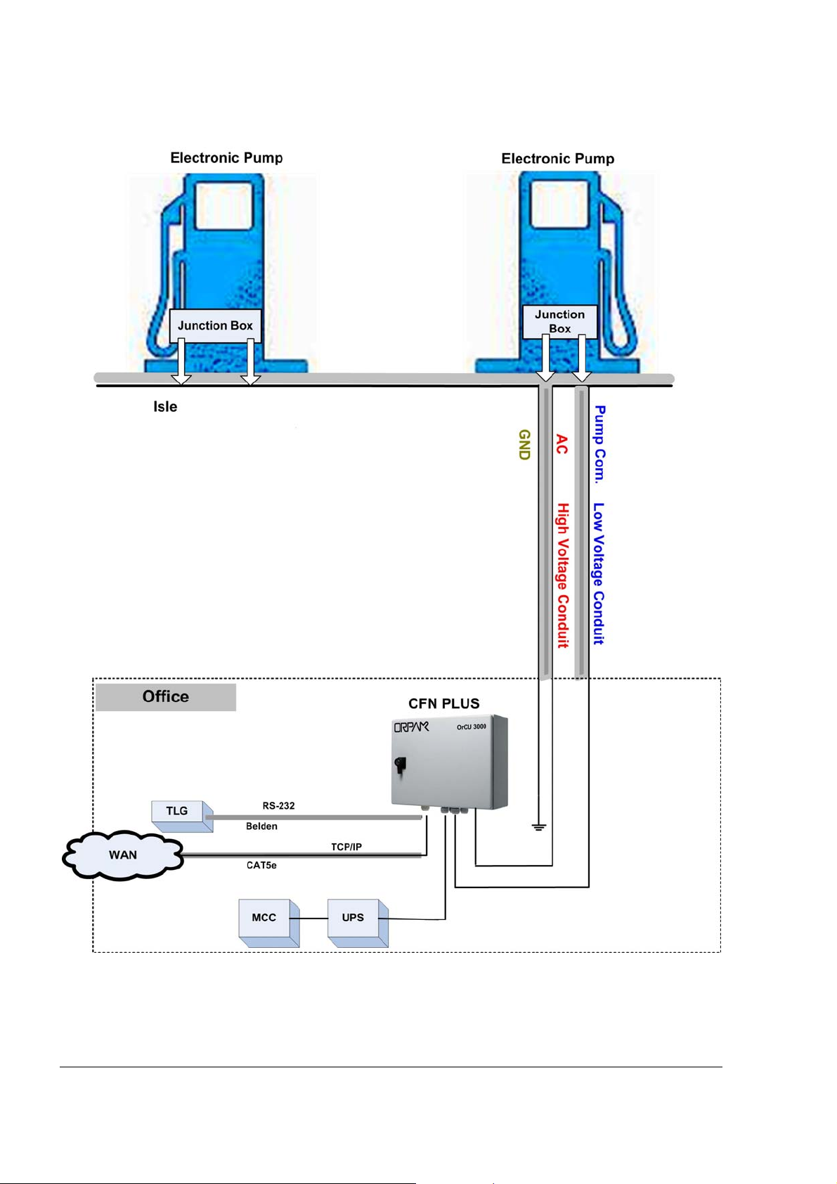
Figure 2-4 Conduits Layout for Electronic Pump
26
CFN PLUS Manual
Page 41
22--66.. CCAABBLLEESS
2-6.1. General
This paragraph describes the requirements and procedures for the insertion of cables in the conduits.
NNOOTTEE
All devices in the system must be connected to the
same electric power phase.
NNOOTTEE
The type of cable needed vary in accordance with
the device it connects. The wire used must be
stranded and not a solid core. Select a cable
specification in accordance with local environment
conditions.
CCAAUUTTIIOONN
For supply connections, use wires suitable for at
least 90°C.
Signal wiring connected in this box must be rated at
least 300 V
2-6.2. Types of Cables
Table 2-2 lists the types of cables in use for the wiring of the CFN PLUS system.
CFN PLUS Manual
27
Page 42

Table 2-2. CFN PLUS, Cables Type
No. Function Type
2
1 AC Power from Office
Power cable, 3x1.5 mm
accordance with local standards
NYY (14 AWG), in
Control to pumps (valves or engine)
In-use signal
Pulser Data communication cable, 300 V RMS, 90ºC,
shielded twisted pair, oil resistant, 24 AWG,
low capacitance below 60 PF/meter similar to
Belden 9729 cable
TLG (RS-232)
3 LAN CAT5E, Shielded, 300 V RMS, 90ºC similar to
Belden 121700A
4 GND Ground cable 0.4" (10.8 mm2)
2-6.3. Cables Routing
Route the cables from the peripherals and the Office to CFN PLUS as listed in Table 2-3 and shown
in Figure 2-3. Proceed as follows:
Table 2-3. CFN PLUS, Cables Routing
No. Functional Description From Through Insert Cable Type (*)
1 Power AC Office High voltage conduit 1
2 GND Office High voltage conduit 4
3 TLG Office Low voltage conduit 2
4 LAN Office Low voltage conduit 3
5 Control, Pump A Pump A High voltage conduit 1
6 In-use, Pump A Pump A High voltage conduit 1
7 Pulser, Pump A Pump A Low voltage conduit 2
(*) Refer to Table 2-2.
28
CFN PLUS Manual
Page 43

2-6.3.1. LAN Cable Routing
Due to FCC requirements, the LAN cable entering the system box should be exposed (near the
entry point, inside the box), and the exposed shielded wire of the cable must be connected to the
nearest ground point on the bottom plate.
Use only LAN cable with RJ-45 metal connector connected to the shield.
22--77.. PPOOWWEERR SSEETTUUPP
2-7.1. General
The power equipment shall be installed in the Main Power Cabinet of the station office. It should
include the following:
• Mains Circuit Control Box (MCC)
• Uninterruptible Power Supply (UPS) – Online ("True") UPS
Figure 2-5 shows the requested connections of the power equipment.
Figure 2-5 Power Equipment Connections
Beside the power equipment, other components shall be connected to the power supply such as the
TLG and the dispensers.
2-7.2. Power Distribution and Grounding
Installation of CFN PLUS in station with mechanical pump requires specific power distribution and
grounding as shown in Figure 2-6.
Installation of CFN PLUS in station with electronic pump requires specific power distribution and
grounding as shown in Figure 2-7.
CFN PLUS Manual
29
Page 44
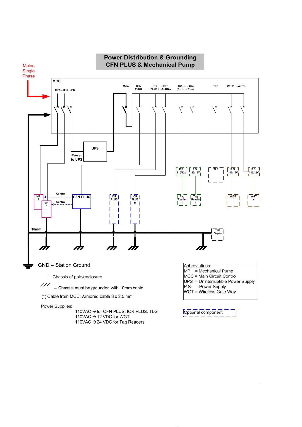
Figure 2-6 Power Distribution and Grounding in Mechanical Pump Station
30
CFN PLUS Manual
Page 45
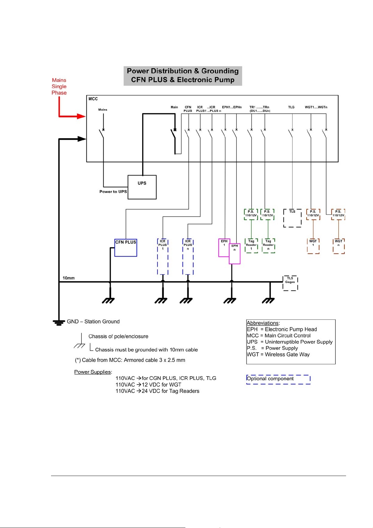
Figure 2-7 Power Distribution and Grounding in Electronic Pump Station
CFN PLUS Manual
31
Page 46

2-7.3. Connecting the Power Equipment
Proceed as follows:
• External Mains
o Connect Mains power to the Mains Circuit Control Box (MCC)
• Uninterruptible Power Supply (UPS)
o Connect the MCC to the UPS.
• If any doubt concerning grounding arises, ask for a ground test performed by a qualified
electrician.
2-7.4. AC Power Supply Setup
CFN PLUS can be fed either 110 VAC or 220 VAC. The Mains cable is first connected to the
terminal block. Between the terminal block and transformer the system uses a Line Filter in order to
attenuate conducted radio frequencies - RFI, electromagnetic interference (EMI) - between the line
and the equipment (see Figure 2-8). AC power is then supplied to an AC/AC High to Low
Transformer – 110/220 VAC to 25 VAC. The transformer requires jumpers' setup for either 110
VAC or 220 VAC Mains input, as shown in Figure 2-9. A settings label is also found on top of the
transformer.
Figure 2-8 CFN PLUS – Power Supply Components and Grounding Studs
32
CFN PLUS Manual
Page 47
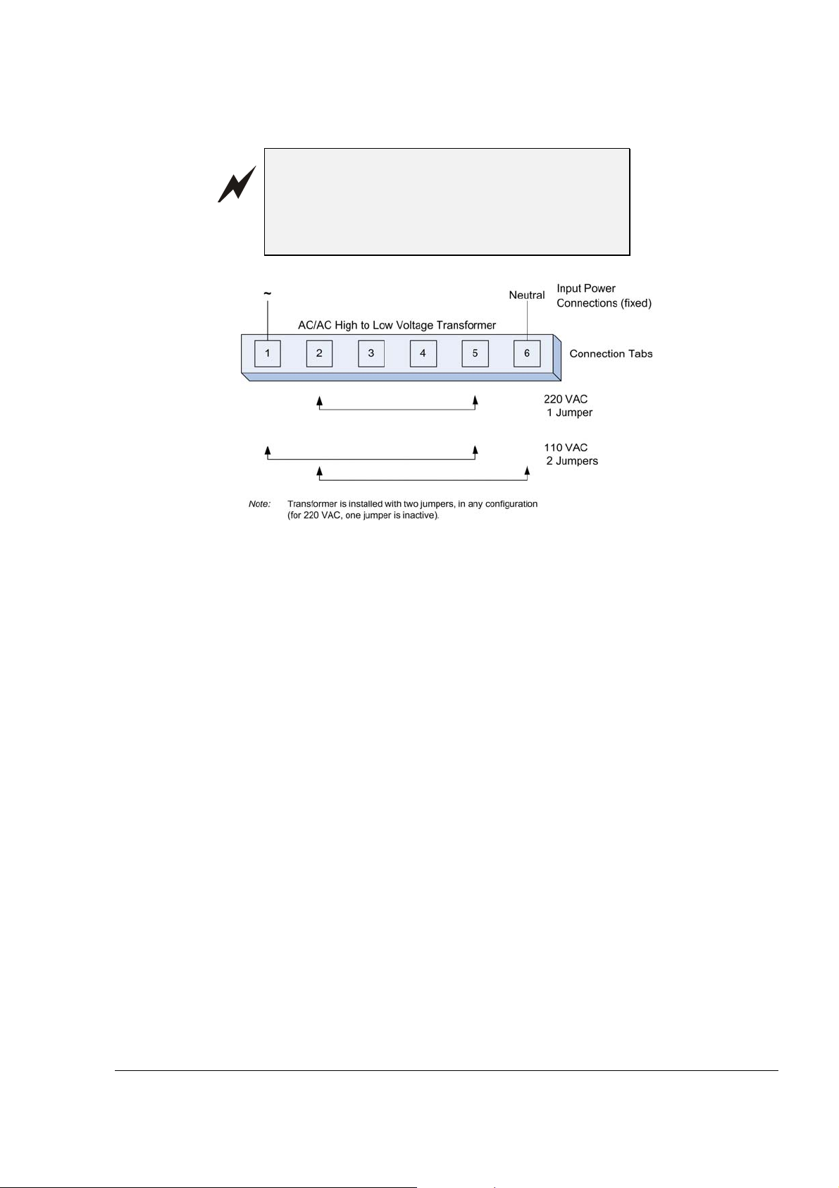
WWAARRNNIINNGG
CFN PLUS is shipped configured for 110 VAC
Mains power supply. Take care to set it accordingly
to your local Mains power supply specifications.
Failure to do so may result in damages.
Figure 2-9 VAC Power Supply – Jumpers Setup
2-7.5. Grounding
Proper system grounding is an extremely important part of the system installation. As with the AC
power, the grounds for all system components should return to the same circuit breaker panel. This
helps you assure a common ground throughout the system, necessary for protection of the RS-485
data loop circuitry. Ground for all system devices should be wired to the breaker panel ground bus
bar, which in turn should be grounded to a ground rod. A conduit ground does not provide sufficient
ground. It is recommended that the neutral and ground bus bars be bonded together when it is not
prohibited by local codes.
See Figure 2-6 and Figure 2-7 for grounding requirement diagrams of station with mechanical
pump and with electronic pump, accordingly.
CFN PLUS includes several grounding studs (see Figure 2-8) in order to comply with the earthing
requirements. The Mains power ground wire should be attached to the stud close to the Line Filter.
CFN PLUS Manual
33
Page 48

22--88.. WWIIRRIINNGG TTHHEE PPEERRIIPPHHEERRAALLSS
2-8.1. Pump Wiring
CFN PLUS is capable of directly driving pump motors up to 3/4 HP at 115 VAC or 1-1/2 HP at 230
VAC. A separate circuit breaker should be supplied for each dispenser. Wire the pump as follows:
• Wire one Mains AC cable from the UPS-MCC to the pump enclosure, for electronic pump
head.
• For an electronic pump, wire RS485 / Current Loop / Tokheim communication cable from
the CFN PLUS to the pump head.
• Wire one 0.4" (10 mm) ground cable from the Mains ground connection to the pump
chassis.
• The communication cable shield must be connected to ground at one end-side only,
preferably at the controller installation side (see Figure 2-10).
• For mechanical pumps, wire the control cable, in-use cable, pulser cable and cable
according to Table 2-2.
Figure 2-10 Communications Cable Wiring
2-8.2. TLG wiring
RS-232/LAN is used for communication between the TLG and CFN PLUS. Follow these
installation requirements when installing the RS-232/LAN communications lines:
NNOOTTEE
These requirements shall be compatible with the
recommendations of the TLG manufacturer.
• Distance: the following distances must be adhered to when installing the
communication lines:
34
CFN PLUS Manual
Page 49

o RS-232: 1 – 50 feet (1 – 15 m) for direct connection to a TLG device.
o LAN: 1- 330 feet (100m) for direct connection to a TLG device
• Conduit: All directly connected RS-232/LAN cables must be in a separate low
voltage conduits away from any AC wires.
• Cable: The type of cable required should be according to the device it is connected
to. The wire used must be stranded and not a solid core. Select a cable specification
in accordance with local environment conditions.
CFN PLUS Manual
35
Page 50

Page 51

0
SSEECCTTIIOONN 33
CCFFNN PPLLUUSS IINNSSTTAALLLLAATTIIOONN PPRROOCCEEDDUURREESS
33--11.. GGEENNEERRAALL
This section provides the installation procedures for the CFN PLUS.
These procedures include:
• CFN PLUS installation
• Wiring
• Post installation check.
33--22.. IINNSSTTAALLLLAATTIIOONN SSPPEECCIIFFIICCAATTIIOONNSS
3-2.1. General
NNOOTTEE
Perform a site survey of the station prior to
installation
Installation procedures and requirements depend, to some extent, on the specific fuel dispenser
models and the site layout. Therefore, use the information in this section to develop installation
plans for each specific installation. Since installation requirements vary widely from case to case,
no installation hardware is supplied by the equipment manufacturer, and installation planners must
develop their own requirements.
The customer should provide an installation plan, designed by an authorized engineer, and
applicable to all authorities having jurisdiction. This plan design should reflect the existing electric
infrastructure of the site.
3-2.2. Precautions and Safety Notes
Prior to actual installation activities, carefully observe the precautions and safety notes detailed in
paragraph 2-2.2 and at the opening pages.
CFN PLUS Manual
37
Page 52
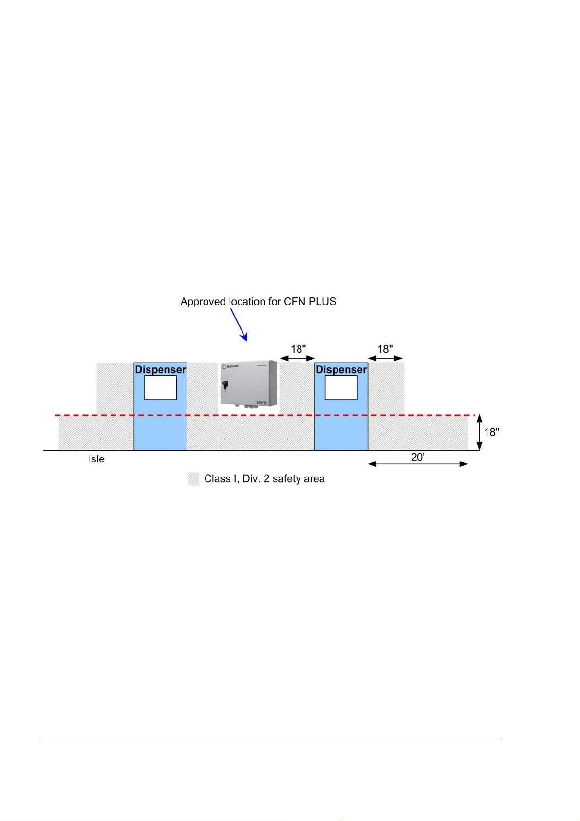
3-2.3. Safety Distances
Figure 3-1 shows the safety distances required for the installation of the CFN PLUS adjacent to
the dispensers. CFN PLUS will be installed in a non hazardous location. When mounting the
CFN PLUS, a minimum clearance of 18 inches between the unit and any of the pumps or the
dispensers must be maintained. This clearance allows room for the wiring and maintenance of
the system.
CFN PLUS is designed and approved for installation and use at a convenient location at or near fuel
Island in the appropriate hazardous (classified) location:
• Where hazardous location is classified as Class 1, Division 2 and it does not extend higher
than 18 inches (0.5m) from surface and
• A minimum safety separation of 18 inches (0.5m) from any nearest pump/dispenser.
Figure 3-1 CFN PLUS – Installation Control Drawing
38
CFN PLUS Manual
Page 53

33--33.. HHOOMMEE BBAASSEE SSTTAATTIIOONN -- OOVVEERRVVIIEEWW
3-3.1. General
Prior to installation, you are required to obtain an overview of the Home Base Station functional
architecture. This overview is required in order to draw an architecture diagram with all
components and their communication links.
Figure 3-2 shows a functional diagram of the links within the Home Base Station with mechanical
pumps. Figure 3-3 shows a functional diagram of the links when operating with electronic pumps.
3-3.2. Home Base Station Architecture
The Home Base Station functional architecture consists of the following levels:
• Main Power Cabinet and Home Base Station forecourt
• Head Office Center
3-3.2.1. Main Power Cabinet
The Main Power Cabinet includes the following components:
• Mains Circuit Control Box (MCC)
• Uninterruptible Power Supply (UPS)
• TLG Controller
3-3.2.2. Home Base Forecourt
The Home Base Forecourt includes the following components:
• CFN PLUS
• Dispenser(s) – up to four mechanical nozzles for each CFN PLUS. For UL
listing; this product has only been evaluated for use with UL Listed Dispensers.
• One or more Underground gas tanks
• TLG probe for each gas tank, For UL listing; this product has only been
evaluated for use with UL Listed TLG’s.
3-3.2.3. Head Office System (Optional)
The Head Office system consists of fully integrated management hardware and software tool that
supports Home Base Station and small gas stations with their sale management of products
including inventory management and reporting.
The Head Office Center is a remote control center that stores, processes and analyzes all the
transactions at the Home Base Station. The Head Office Station provides an integrated retail
solution.
CFN PLUS Manual
39
Page 54

Figure 3-2 Home Base Station with Mechanical Pumps – System Diagram
40
CFN PLUS Manual
Page 55

Figure 3-3 Home Base Station with Electronic Pumps – System Diagram
CFN PLUS Manual
41
Page 56

33--44.. MMAAPPPPIINNGG TTHHEE SSIITTEE–– EEXXAAMMPPLLEE
3-4.1. General
This paragraph shows an example of the mapping of a site. This procedure consists of the
following steps (see also Appendix A):
• Locating and mapping all objects of the site
• Assigning logical identifications (Id.) to the devices
• Assigning the Ethernet and Serial addresses of devices linked to the network
• Obtaining a functional and physical Map of the devices in the site.
3-4.2. Locating all objects of the site
• Locate the roads around the site
• Locate the islands and their dispensers
• Locate the fuel tanks
• Locate the intended position of the CFN PLUS
• Draw a basic map of the site with all the objects
3-4.3. Assigning Logical IDs
3-4.3.1. To each fuel tank
• Assign the tank sequential number (coordinated with the station manager)
• Assign its fuel code and name
• Assign its TLG Probe (AP) Id.
3-4.3.2. To each Dispenser Unit
• Assign an id. to every dispenser name and Pump Server
• Assign an id. to every dispenser pump (P)
• Assign an id. to every pump CPU addresses if any
• Assign an id. to its nozzles (N)
• Assign to each nozzle the tank (T) Id. to whom it is linked.
3-4.3.3. To CFN PLUS
• Assign the CFN PLUS its id. after installation on a flat surface
3-4.4. Mapping
• Draw a map of the site.
• Use the map methodology and Ids. For later setup configuration.
42
CFN PLUS Manual
Page 57

33--55.. CCOONNNNEECCTTIIOONNSS TTOO CCFFNN PPLLUUSS
All connections to the CFN PLUS must be performed to the Terminal Block located at the bottom
of the CFN PLUS pedestal by (see Figure 3-4). The required connections are:
1. Dispenser wiring connections:
• Pulser (Low Voltage)
• In Use signal (High voltage)
• Valve (High voltage)
2. Communications
• RS-232 to TLG Controller to Gas Tank
• RS-485 for peripheral device
• Pump communication line (e.g. Current Loop, RS485, Tokheim, RS-422)
3. Mains AC Power and Ground
4. LAN connection.
Figure 3-4 CFN PLUS Terminal Block, Power and LAN Connections
CFN PLUS Manual
43
Page 58

33--66.. IINNSSTTAALLLLIINNGG TTHHEE CCFFNN PPLLUUSS
3-6.1. General
CFN PLUS is mounted in the safe area of the Home Base Gas Station on a wall or any flat surface
up from ground (panel, billboard).
CFN PLUS is installed with wall mounting brackets that provide a wall distance of 10 mm. The
brackets are attached to four holding padded holes in the inner rear wall of CFN PLUS.
3-6.2. Installation Procedure Steps
Installation of CFN PLUS consists of the following general steps:
• Installing CFN PLUS on a wall
• Running cables through the conduits to CFN PLUS
• Wiring CFN PLUS
3-6.3. Site Preliminary Setup Procedures
Proceed as follows:
1. Determine the spot for CFN PLUS installation
2. Run cable conduits for each type of cables to the spot:
• One High Voltage conduit from the dispenser
• One Low Voltage conduit from the dispenser
• One Low Voltage conduit from the Office
• One High Voltage conduit from the Mains Distribution Box
3. Run the cable conduits to the hole.
3-6.4. Installation Assembly Parts
Table 3-1 lists the assembly parts for the installation of the CFN PLUS.
44
CFN PLUS Manual
Page 59

Table 3-1. CFN PLUS, Assembly Parts
Item No. Part Number Description Qty
1 800938652 - 800938715 CFN PLUS 1
2 819022200 Wall Mount Kit 1
2a 814423100 Wall Bracket 4
2b 815122000 Nut M8 4
2c 815222000 Screw, M8x20, Hexagon Head 4
2d 815322000 Washer, Flat, M8 4
2e 815322100 Washer Spring M8 4
2f 815322400 Washer, Insulator, M8 4
3-6.5. Installation Procedures
Proceed as follows:
Note: If the wall mount is already installed, go to step 4.
1. Open CFN PLUS enclosure
2. Turn CFN PLUS enclosure (1 in Table 3-1) so you face its rear panel (see Figure 3-5)
3. Attach to each support hole in the rear panel a wall bracket (see , 2 in Table 3-1), with nut,
M8x20 screw and flat washer (3/4/5 in Table 3-1). Set the bracket so that they fit to the
proper installation, as shown in Figure 3-6. The wall bracket dimensions are provided in
Figure 3-7.
4. Set the CFN PLUS enclosure (with wall brackets) in the spot and mark the four holes
location from brackets for drilling. Make sure you select place that will allow you to open
completely the CFN PLUS door.
5. Drill four holes in the installation spot (fit for M4 screws)
6. Insert four wall anchors (or equivalent) in the holes
7. Set the CFN PLUS enclosure on the spot so that its installation holes fit with the anchors
8. Insert four M4 screws (6 in Table 3-1) and M4 flat washers (7 in Table 3-1) and secure CFN
PLUS enclosure. Verify that CFN PLUS enclosure is firmly held, and provides a distance
from wall.
9. Take care that all power and communication cables pass through the holes in the bottom
panel
CFN PLUS Manual
45
Page 60
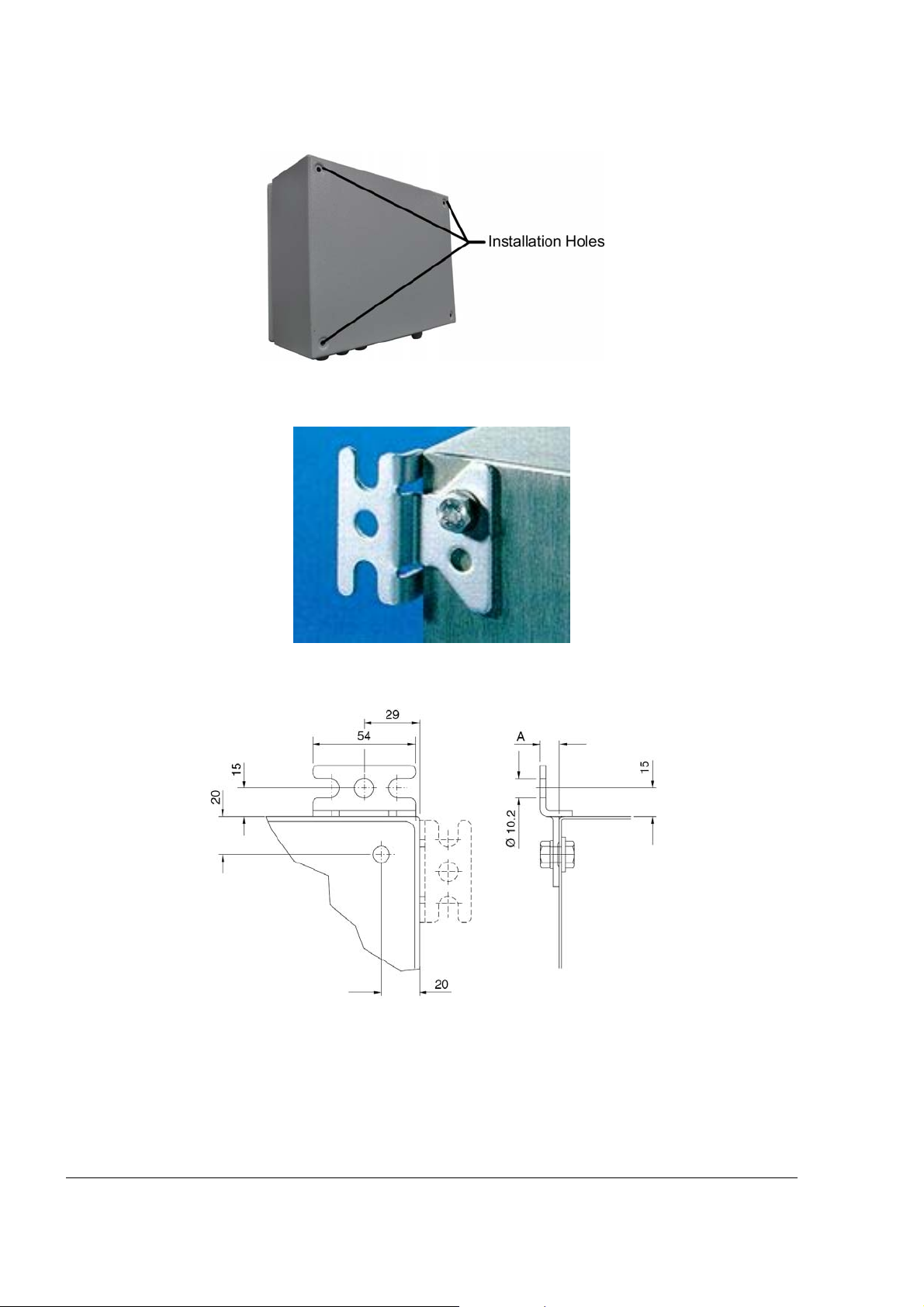
Figure 3-5 Rear Panel Support Holes
Figure 3-6 Wall Bracket, Installation Example
Figure 3-7 Wall Bracket, Dimensions (mm)
46
CFN PLUS Manual
Page 61

3-6.6. Sealing Conduits
The conduits shall be sealed in accordance with NFPA requirements and local regulations, to
prevent the passage of gases through conduits, cables and conductors. The fittings are requested
wherever volatile liquids or gases are present in the surroundings (see Figure 3-8).
Figure 3-8 Conduits Sealing
CFN PLUS Manual
47
Page 62

33--77.. WWIIRRIINNGG
3-7.1. General
After completing the installation procedure, perform the following wiring procedures. The wiring is
performed in the CFN PLUS Terminal Block only.
The wires should be pulled from the conduits that protrude from the Installation Base, or in the
opposite direction, from the Terminal Block to the device in the Home Base Station.
3-7.2. Types of Wiring
The wiring in the Terminal Block differs in accordance with the type of pump installed in the Home
Base Station. There are two types of pumps:
• Mechanical Pump
• Electronic Pumps
The following paragraphs provide the wiring requirements for each type of pump.
3-7.3. Wiring Requirement
For any type of pump and wire, prior to inserting a wire, proceed as follows:
1. Insert all wires with a terminal lug only.
2. Use the proper Terminal Crimper to attach the lug to the wire.
3. For UL Listing, The Terminal Lug must be a UL recognized components.
Figure 3-9 Terminal Lug
TTIIPP
Mark each cable at its both ends with a number or
sign that will identify its functionality in the future.
3-7.4. Types of Cable
The following cables are in required for the CFN PLUS installation:
48
CFN PLUS Manual
Page 63

• Power cable – In accordance with local regulations
• LAN cable – CAT5E
• RS232/485/422/Tokheim/Pulser – Communication cable, twisted pair, separately
shielded, low capacitance
NNOOTTEE
The shield should be connected to Ground in one
side of the cable only, preferably on the CFN PLUS
side.
• Antenna cable - Communication cable, Twisted pair, separately shielded, low
capacitance
33--88.. MMEECCHHAANNIICCAALL PPUUMMPP –– WWIIRRIINNGG
3-8.1. General
The wiring for mechanical pumps is provided in two modes:
• Figure 3-11 lists the wiring in the sequential order of the terminals. This table provides the
signal name and a functional description of the signal.
• Figure 3-11 shows the wiring list for connection to the Terminal, as published in the Wiring
Label added to the power protective window (see Figure 3-12). The Wiring Label follows
the physical location of the wires in the Terminal Block, as shown in Figure 3-11.
3-8.2. Mechanical Pump – Terminal Block - Pin-Out
Connections
The CFN PLUS Terminal Block connections for a Mechanical Pump are listed in the following
table.
CFN PLUS Manual
49
Page 64

Table 3-2. CFN PLUS Terminal Block - Mechanical Pump – Connections Definition
Terminal No. Signal Name Functional Description
1 BARRIER 1 (-) N/A
2 BARRIER 2 (-) N/A
3 BARRIER 3 (-) N/A
4 BARRIER 4 (-) N/A
5 BARRIER 1 (+) N/A
6 BARRIER 2 (+) N/A
7 BARRIER 3 (+) N/A
8 BARRIER 4 (+) N/A
9 TX-RS232 Transmit (optional RS232 connection)
10 GND-RS232 RS232 Ground (optional RS232 connection)
11 RX-RS232 Receive (optional RS232 connection)
12 RS-485 (+) (+)RS 485 (optional equipment interface)
13 RS-485 (-) (-)RS 485 (optional equipment interface)
14 RS-485 GND (Gnd) Rs485 (optional equipment interface)
15 Pulser 1 Pulser Input – Nozzle 1
16 Pulser 2 Pulser Input – Nozzle 2
17 Pulser 3 Pulser Input – Nozzle 3
18 Pulser 4 Pulser Input – Nozzle 4
19 GND 1 P Nozzle Grounding – Nozzle 1
20 GND 2 P Nozzle Grounding – Nozzle 2
21 GND 3 P Nozzle Grounding – Nozzle 3
22 GND 4 P Nozzle Grounding – Nozzle 4
23 +12V 1 P +12 VDC Output to Pulser – Nozzle 1
24 +12V 2 P +12 VDC Output to Pulser – Nozzle 2
25 +12V 3 P +12 VDC Output to Pulser – Nozzle 3
26 +12V 4P +12 VDC Output to Pulser – Nozzle 4
27 IN USE 1 A (AC) Handle Up – AC In Use signal input - Nozzle 1
28 IN USE 2 A (AC) Handle Up – AC In Use signal input - Nozzle 2
29 IN USE 3 A (AC) Handle Up – AC In Use signal input - Nozzle 3
30 IN USE 4 A (AC) Handle Up – AC In Use signal input - Nozzle 4
31 IN USE 1 B(-) (Return) Handle Up – AC In Use signal return - Nozzle 1
32 IN USE 2 B(-) (Return) Handle Up - AC In Use signal return - Nozzle 2
33 IN USE 3 B(-)(Return) Handle Up – AC In Use signal return - Nozzle 3
50
CFN PLUS Manual
Page 65

Table 3-2. CFN PLUS Terminal Block - Mechanical Pump – Connections Definition
Terminal No. Signal Name Functional Description
34 IN USE 4 B(-)(Return) Handle Up – AC In Use signal return - Nozzle 4
35 LOAD 1 Pump control output - Nozzle 1
36 LOAD 2 Pump control output - Nozzle 2
37 LOAD 3 Pump control output - Nozzle 3
38 LOAD 4 Pump control output - Nozzle 4
39 LINE 1 Pump control 12/24 VDC Input - Nozzle 1
40 LINE 2 Pump control 12/24 VDC Input - Nozzle 2
41 LINE 3 Pump control 12/24 VDC Input - Nozzle 3
42 LINE 4 Pump control 12/24 VDC Input - Nozzle 4
43 LINE IN (115/230V) Input AC voltage
44 NEUTRAL IN (115/230V) Neutral line
45 GROUND IN Ground
Figure 3-10 Terminal Block
CFN PLUS Manual
51
Page 66

Figure 3-11 Terminal Block – Mechanical Pump - Wiring List Label
Figure 3-12 Terminal Block –Wiring List Label Installed on Protective Cover
52
CFN PLUS Manual
Page 67

3-8.3. Mechanical Pump - Required Connections
This paragraph describes the required wiring connections between the mechanical pump and the
CFN PLUS. Figure 3-13 shows a schematic diagram of a single dispenser connections and Figure
3-14 shows a schematic diagram of a twin dispenser connections. Figure 3-15 shows a detailed
wiring diagram between the CFN PLUS terminal block and the pump components.
Pulse Input Wires: The dispenser outputs pulses to the system by means of the Pulser unit,
installed inside the pump head. The Pulse rate per volume (liter/gallon)
is determined by the Pulser unit. It is programmed as a "factor" by the
Head Office controller.
Handle Status Input
Wires:
Authorization Output
Wires:
The handle signal is used to signal the system that the pump is "In Use"
mode. . When the dispenser handle is lifted this contact will close. This
should signal the system that the pump is "In Use" or that the
transaction ended. (see FIGURE 3-13).
The dispenser requires an authorization signal from the CFN PLUS to
start a sale transaction. Without this authorization signal, the electric
valve (or pump) will not open and the sale transaction will not begin.
The CFN PLUS sends the authorization signal in the form of an AC
power signal to the valve. When the dispenser receives the authorization
signal, fuel is flow.
CFN PLUS Manual
53
Page 68
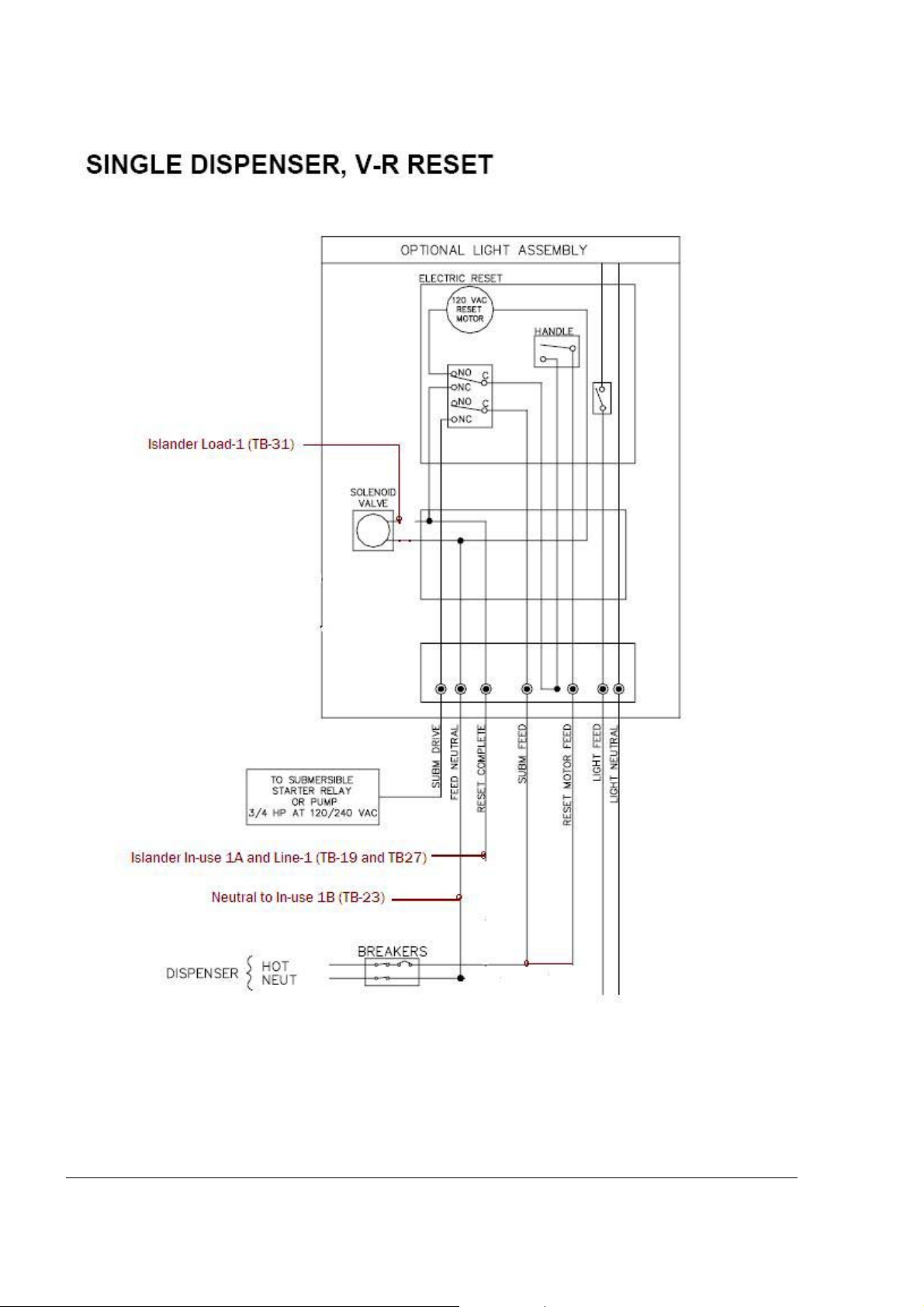
Figure 3-13 Mechanical Pump – Single Dispenser Connections
54
CFN PLUS Manual
Page 69

Figure 3-14 Mechanical Pump – Twin Dispenser Connections
CFN PLUS Manual
55
Page 70
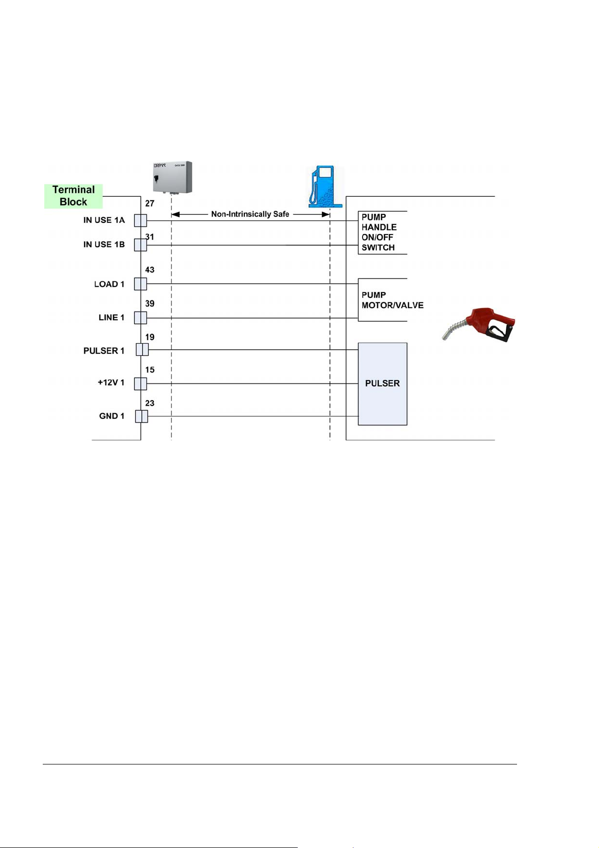
Figure 3-15 CFN PLUS and Mechanical Pump - Terminal Block Detailed Connections
56
CFN PLUS Manual
Page 71

3-8.4. Mechanical Pump - Pulser Connections
This paragraph describes the required wiring connections between the Pulser in the mechanical
pump and the CFN PLUS. The system can accept many types of pulsers, please contact Gasboy for
more information. Two types of pulser can be found in trucks:
- Electronic pulser
- Mechanical pulser
Connect the CFN PLUS to the Pulser in accordance to its characteristics.
NNOOTTEE
Pulser should be installed in accordance with the
pulser manufacturer's instructions. Some pulsers do
not have a barrier, in that case you must add a pulser
barrier! Barriers are not provided with CFN PLUS.
3-8.4.1. Electronic Pulser
• 3-Wire Pulser, that requires an external power source (12V) in order to operate
Figure 3-16 shows a schematic diagram of the connections between the Terminal Block and a
3-wire Pulser.
Figure 3-16 Terminal Block and 3-Wire Pulser – Wiring Connections
CFN PLUS Manual
57
Page 72
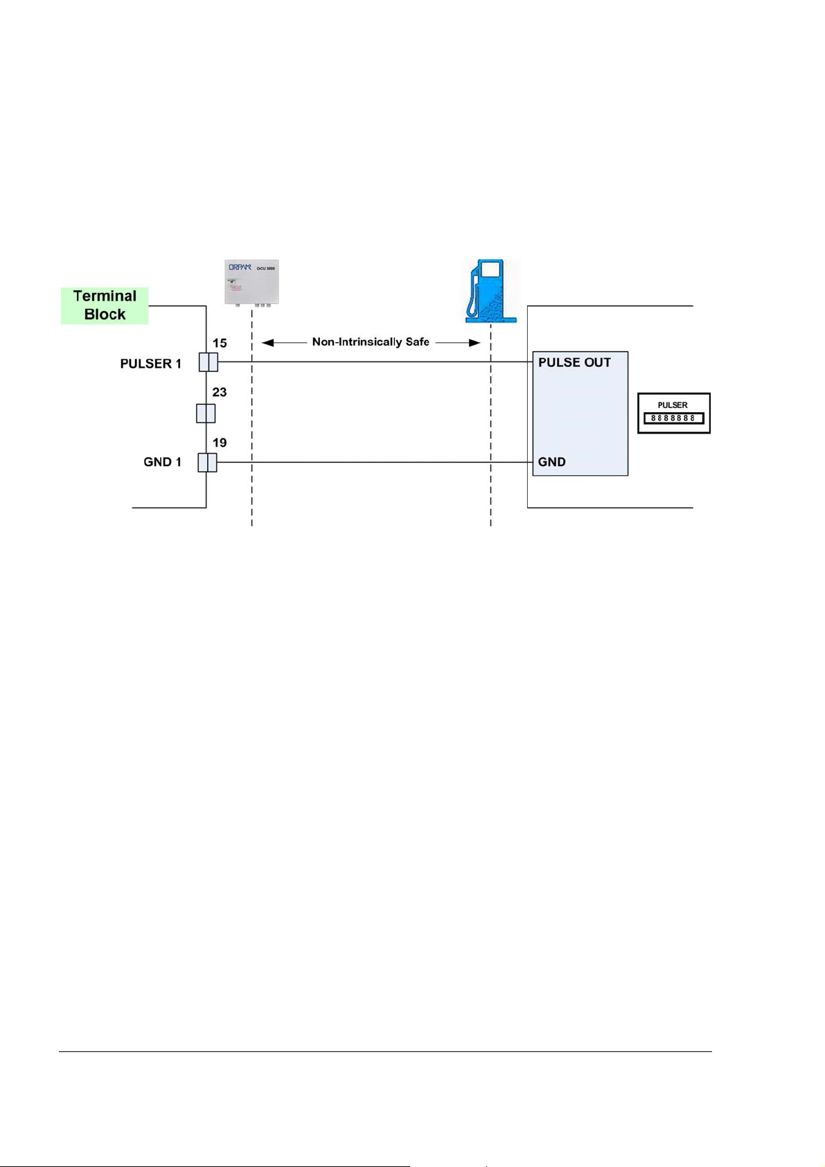
3-8.4.2. Mechanical Pulser
• 2-Wire Pulser, powered by the CFN PLUS.
Figure 3-17 shows a schematic diagram of the connections between the Terminal Block and a
2-wire Pulser.
Figure 3-17 Terminal Block and 2-Wire Pulser – Wiring Connections
58
CFN PLUS Manual
Page 73

33--99.. EELLEECCTTRROONNIICC PPUUMMPP –– WWIIRRIINNGG DDEESSCCRRIIPPTTIIOONN
3-9.1. General
The wiring in the Terminal Block differs in accordance with the type of electronic pump installed in
the Home Base Station. There are several types of electronic pumps. The wiring of some of the
major one are described below. The major pumps are:
• Tokheim
• Current Loop
• RS-485
• RS - 422
See Figure 3-18 for the wiring list label applied within the inner wall of the unit. This label consists
of a wiring list table for the Terminal block. You are requested to connect the Forecourt equipment
to OrIC in accordance with this table:
• The rows are the connection ports in the Terminal Block, in an ascending order.
• Each column is dedicated for a specific pump.
• Each cell defines the signal attached to the Terminal Block port.
The wiring of some of the major pumps is described below.
CFN PLUS Manual
59
Page 74
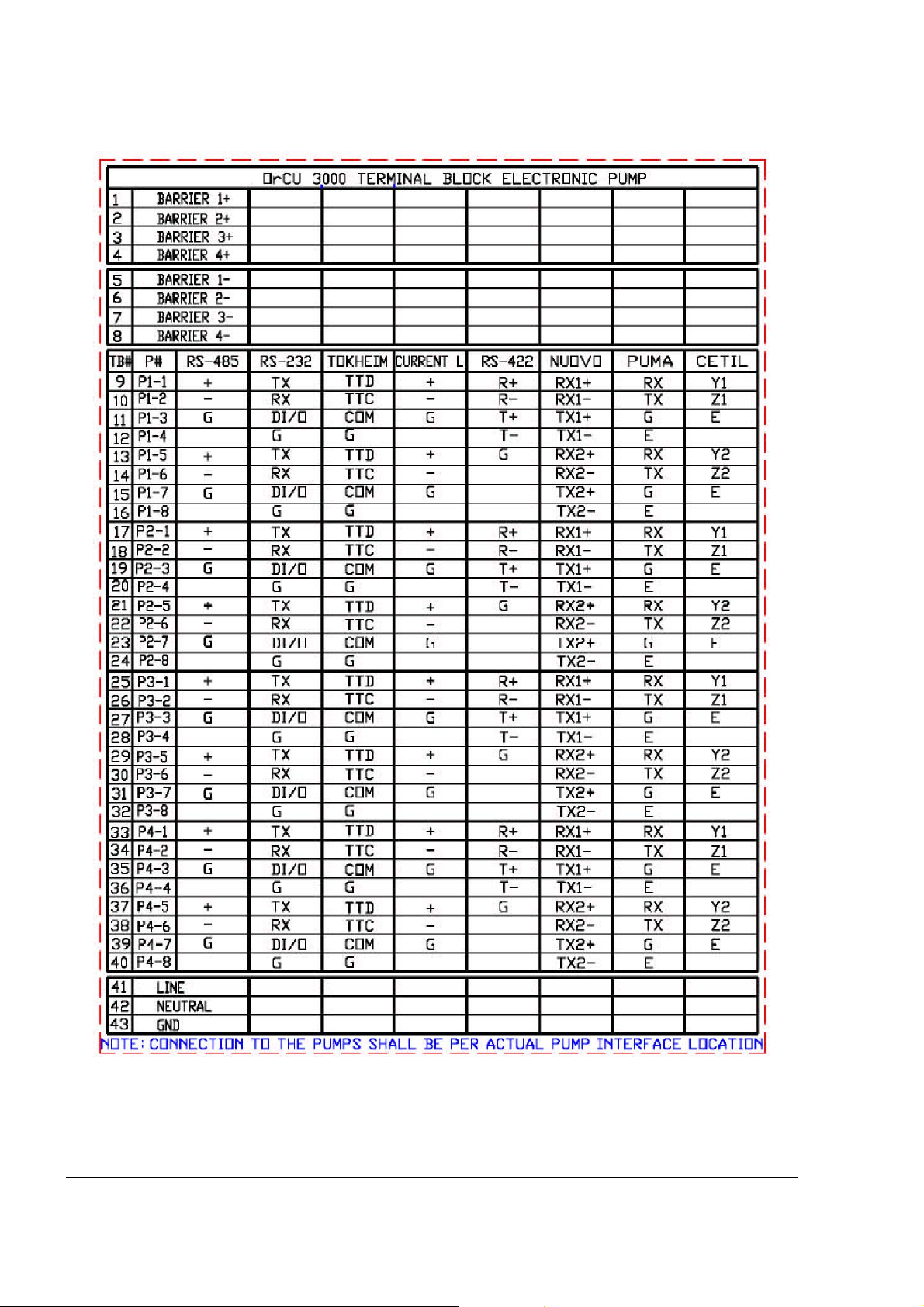
Figure 3-18 CFN PLUS Terminal Block – Wiring List Label
60
CFN PLUS Manual
Page 75

3-9.2. Tokheim Electronic Pump
The wiring for the Tokheim electronic pump is provided as follows:
• Figure 3-19 shows the specific wiring connections between CFN PLUS and the Tokheim
pump nozzle, and the terminals that differ from the Mechanical Pump.
• Figure 3-18 shows the wiring list for connection to the Terminal, as published in the Wiring
Label added to the inner door. The Wiring Label follows the physical location of the wires
in the Terminal Block, as shown in Figure 3-10.
Figure 3-19 Tokheim Electronic Pump - Wiring Diagram
CFN PLUS Manual
61
Page 76
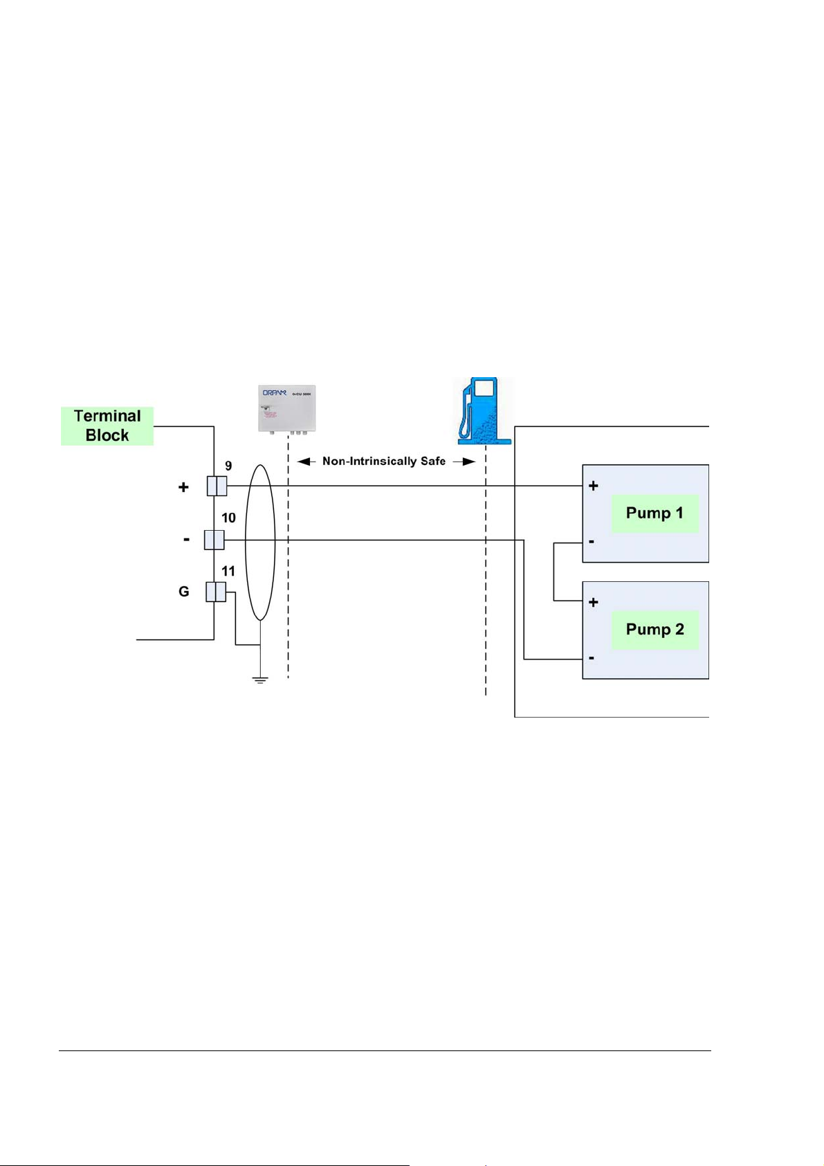
3-9.3. Current Loop Electronic Pump
The wiring for the Current Loop electronic pump is provided as follows:
• Figure 3-20 shows the specific wiring connections between CFN PLUS and the Current
Loop pump nozzle, and the terminals that differ from the Mechanical Pump. The figure
shows the serial connection between two Current Loop pumps and the Terminal Block.
• Figure 3-18 shows the wiring list for connection to the Terminal, as published in the Wiring
Label added to the inner door. The Wiring Label follows the physical location of the wires
in the Terminal Block, as shown in Figure 3-10.
Figure 3-20 Current Loop Electronic Pump - Wiring Diagram
62
CFN PLUS Manual
Page 77

3-9.4. RS-485 Electronic Pump
The wiring for the RS-485 electronic pump is provided as follows:
• Figure 3-21 shows the specific wiring connections between CFN PLUS and the RS-485
pump nozzle, and the terminals that differ from the Mechanical Pump. The figure shows the
parallel connection between two RS-485 pumps and the Terminal Block.
• Figure 3-18 shows the wiring list for connection to the Terminal, as published in the Wiring
Label added to the inner door. The Wiring Label follows the physical location of the wires
in the Terminal Block, as shown in Figure 3-10.
Figure 3-21 RS-485 Electronic Pump - Wiring Diagram
CFN PLUS Manual
63
Page 78

33--1100.. WWIIRRIINNGG TTOO GGEENNEERRAALL CCOOMMPPOONNEENNTTSS
3-10.1. General
The following paragraphs show the specific wiring between the CFN PLUS Terminal Block and
components common in both types of Home Base Stations, either with mechanical or electronic
pump.
3-10.2. Connection to TLG Controller
Figure 3-22 shows the required connection between the TLG controller in the gas tank and the
Terminal Block (RS-232 type).
Figure 3-22 Terminal Block – TLG Wiring Link
64
CFN PLUS Manual
Page 79

33--1111.. PPOOSSTT--IINNSSTTAALLLLAATTIIOONN CCHHEECCKKLLIISSTT
After completing the installation procedure, inspect carefully the connection between the CFN
PLUS and the external power mains and the data sources.
In particular, pay attention to the following issues:
• Correct wiring
o Is all the wiring inserted in metal conduits?
o Is the AC and the DC wiring inserted in separate conduits, throughs and so
on.
o Is the system/peripheral equipment powered on a separate dedicated breaker?
o Is the system grounded properly?
o Are the cables correctly routed in the station?
o Are the communication lines under the maximum allowable distance?
RS-232: 50 feet (15m)
RS-485: 330 feet (100m)
Antenna wire:
• 330 feet (100m) for VIU
• 50 feet (15m) for FuelOpass
• Clean dirt and wire remnants
In case problems are detected after installation or during operation, repeat the post-installation
checks listed above.
33--1122.. CCFFNN PPLLUUSS SSEETTUUPP
Please refer to the SiteOmat Setup Manual, document number MDE-4817.
CFN PLUS Manual
65
Page 80

Page 81

0
SSEECCTTIIOONN 44
MMAAIINNTTEENNAANNCCEE
44--11.. GGEENNEERRAALL
This section provides general maintenance instructions for the CFN PLUS.
44--22.. CCLLEEAANNIINNGG
The CFN PLUS itself as a standalone unit should be cleaned periodically at short intervals, due to
the harsh environment of the Home Base Station where they operate.
The following instructions are valid for the CFN PLUS box and for OrTR (Optional).
• Clean the OrTR front panel with a damp cloth only.
• Clean the box and other devices with a damp cloth only.
CCAAUUTTIIOONN
DO NOT use any solvents such as thinner or
benzene.
CFN PLUS Manual
67
Page 82

Page 83

0
55--11.. FFUUEELLOOMMAATT GGLLOOSSSSAARRYY
ComVerter
DataPass
FHO
MPI
MPI-C
NIS
NR
OrCU
LAN/232/485/422/C.L./Tokheim Communication Converter
Vehicle Data Transceiver
Fleet and Fuel Head Office
Mechanical Pump Interface
Mechanical pumps Interface Card
Non-Intrinsically Safe
Nozzle Reader (Wireless Nozzle Reader unit)
Orpak embedded Controller Unit
SSEECCTTIIOONN 55
GGLLOOSSSSAARRYY
OrCU 3000
OrIC
OrIT
OrPT
OrTC
OrTR
POS
SAM
TLS
VBIS
VIS
Orpak site Controller Unit
Orpak Island Controller
Orpak Island Terminal
Orpak/Outdoor Payment Terminal (display, Keyboard, key reader,
magnetic card reader, LED’s, buzzer; install in fueling area)
Orpak Tanker Controller
Orpak Tag Reader
Point Of Sale
Security Application Module (security card in the VIT/UPI)
Tank Level System (measuring fuel tank level in station)
Vehicle Bus Information System
Vehicle Information System
CFN PLUS Manual
69
Page 84

VIT
Vehicle Information Transceiver
VIU
WGT
µVIT ( = micro VIT)
Vehicle Identification Unit (VIU3/35/45)
Wireless Gateway Terminal
Mini VIT with RF/LAN/485 communication
55--22.. CCOOMMMMUUNNIICCAATTIIOONN GGLLOOSSSSAARRYY
Access Point
Ad Hoc
Backbone
BSS
DES
An internetworking device that seamlessly connects wired and wireless networks
together.
A peer- to-peer wireless network without Access Point. A group of wireless clients
consistent an independent wireless LAN.
The core infrastructure of a network, the portion of the network that transports
information from one central location to another central location. The information
is then off-loaded onto a local system.
Basic Service Set. An Access Point associated with several wireless stations.
LANs with high level of security. A method of data encryption.
DHCP
ESS
ESSID
Ethernet
Infrastructure
LAN
Roaming
TCP/IP
Triple DES
WAN
Dynamic Host Configuration Protocol.
Extended Service Set. More than one BSS can be configured as an Extended
Service Set. An ESS is basically a roaming domain.
Extended Service Set Identifier. The length of the ESSID information is between 0
and 32 octets. A zero-length identifier indicates the broadcast SSID.
A popular local area data communications network, originally developed by Xerox
Corp., which accepts transmission from computers and terminals. Ethernet operates
on 10/100 Mbps transmission rate over shielded coaxial cable or over shielded
twisted pair telephone wire.
An integrated wireless and wired LAN is called an infrastructure configuration.
Local Area Network
A function that allows one to travel with a mobile end system (wireless LAN
mobile station, for example) through the territory of a domain (an ESS, for
example) while continuously connecting to the infrastructure.
Communication protocol used in Ethernet/Internet.
A method of data encryption.
Wide Area Network
70
CFN PLUS Manual
Page 85

WEP
Wired Equivalent Privacy. The optional cryptographic confidentiality algorithm
specified by IEEE 802.11 used to provide data confidentiality that is subjectively
equivalent to the confidentiality of a wired local area network (LAN) medium that
does not employ cryptographic techniques to enhance privacy.
WG
Wireless Gateway
CFN PLUS Manual
71
Page 86

Page 87

0
AAPPPPEENNDDIIXX AA
SSIITTEE SSUURRVVEEYY
SSTTAATTIIOONN IINNFFOORRMMAATTIIOONN FFOORRMMSS
((TToo bbee ffiilllleedd dduurriinngg ssiittee ssuurrvveeyy))
n
HHoommee BBaassee SSttaattiioon
Date:_______
Prepared by:
Name:______ e-mail:__________ Phone:_______
Gas station info:
Company name __________________ Tel: ____________
Contact person: __________________ Mobile Phone:_____
Fax: ____________
A. STATION INFORMATION
• Power line 110VAC 220VAC Other____
• Power stabilizer/UPS available? ______________ Spec _________________
• Station name __________________________
• Location _________________________
• FCC Tel. No._____________ / Direct connect _____________
CFN PLUS Manual
73
Page 88

• Internet connectivity method (Modem, GPRS, cable, frame relay,
SAT,ADSL etc) ______________
• Number of dispensers (to be connected to FCC): ______
• Number of nozzles (to be connected to FCC): ______
• Number of Authorizers required _____
• TLS type_________________________
B. STATION MODE OF OPERATION
How do the pumps being authorized?
o Console
o Preset Money, Preset Volume
o From office
o Auto-authorized (free mode)
Do they provide receipts? Y/N (attach samples)
D. DISPENSER INFORMATION (CONNECTED TO FCC)
• Dispenser No._________________
• Manufacturer_________________
• MODEL___________________________
• TYPE:
Mechanical: have electronic pulse out ?_____ Pulses/liter factor_________
Electronic (protocol communication)____________
• Pump link – Current Loop, RS-485, Other ___________________
• Type of wire used for pump link; is it shielded ?______________
• Number of CPU Heads per dispenser ______________________
• Number of Nozzles __________________
• Decimal Point: Price________ Volume _______ Total _______
74
CFN PLUS Manual
Page 89

• How many different dispenser TYPES in the station?_______________
E. NOZZLE EQUIPMENT-1
• HOSE SIZE : 3/4” 1” other________
• Hose Length ___________________
• Break Away : Yes No Location on the hose:________
• Vapor Recovery: Yes No
• NOZZLE/HOSE THREAD: INCH (NPT) MILLIMETER (DSP)
• HOSE THREAD : Male Female
• MANUFACTURER: ___________________
• MODEL: ___________________________
• DIAMETER OF NOZZLE SPOUT: ________
•
F. NOZZLE EQUIPMENT-2
• HOSE SIZE : 3/4” 1” other________
• Hose Length ___________________
• Break Away : Yes No Location on the hose:________
• Vapor Recovery: Yes No
• NOZZLE/HOSE THREAD: INCH (NPT) MILLIMETER (DSP)
• HOSE THREAD : Male Female
• MANUFACTURER: ___________________
• MODEL: ___________________________
• DIAMETER OF NOZZLE SPOUT: ________
CFN PLUS Manual
75
Page 90

G. CONDUIT
Exists _________ Can be used ____________ Sealed ______________
Need new conduit _____________ Type of surface ________________
Tanks
Is tank gage reading required Yes No
How many tanks and what type ?_______________________________________
Do they use a TLS, what type ?_________________________________________
How do they read tanks today ?_________________________________________
H . Site inspection
Pay attention to the following:
• Photos of : Nozzle, Hose, Pump, Isle, Station
• Distances
• Location of office (to install FCC), Pumps, Tanks, Isles etc.
• Broadcast antennas, Power line cables/tower, Generators etc.
(draw the station and attach photos):
76
CFN PLUS Manual
Page 91

Color scream and Graphics that may affect the appearance of our equipment at the
station (like the color of OrPT Box)
Drawings/photos
CFN PLUS Manual
77
Page 92

Page 93

AAPPPPEENNDDIIXX BB
WWIIRRIINNGG DDIIAAGGRRAAMM
This appendix provides the wiring diagram of the CFN PLUS, as follows:
• Figure A-1 CFN PLUS – Wiring Diagram (Mechanical Pump)
• Figure A-2 CFN PLUS – Wiring Diagram (Electronic Pump)
CFN PLUS Manual
79
Page 94

Figure A-1 CFN PLUS – Wiring Diagram (Mechanical Pump)
80
CFN PLUS Manual
Page 95
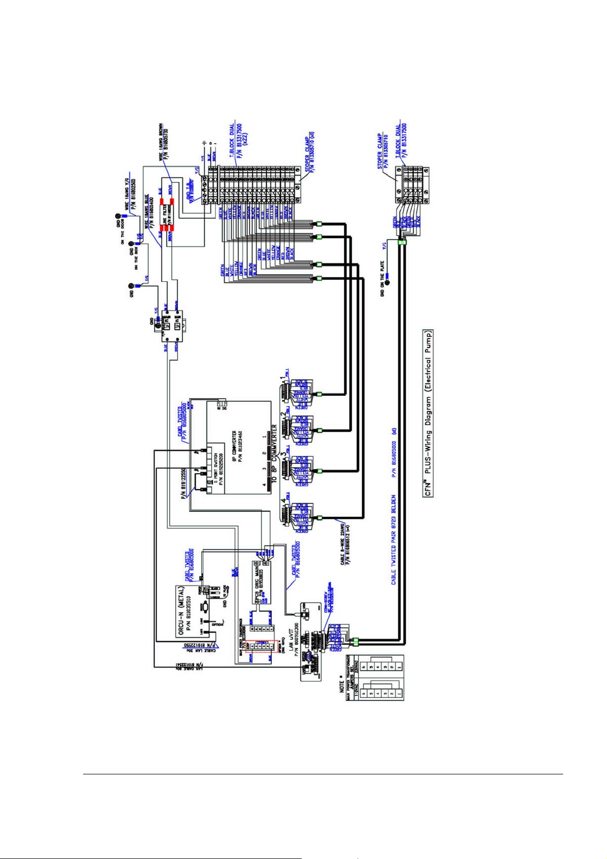
Figure A-2 CFN PLUS – Wiring Diagram (Electronic Pump)
CFN PLUS Manual
81
 Loading...