

Page 1

CFN SERIES
ISLANDER II
INSTALLATION MANUAL
C35963
GASBOY INTERNATIONAL LLC
Page 2

GASBOY
CFN SERIES
ISLANDER II
INSTALLATION MANUAL
C35963
Rev. 03/07/03
The information in this document is confidential and proprietary. No further disclosure shall be made
without permission from Gasboy International LLC. Gasboy International LLC believes that the information
in this document is accurate and reliable. However, we assume no responsibility for its use, nor for any
infringements of patents or other rights of third parties resulting from its use. We reserve the right to make
changes at any time without notice.
Copyright 2003 by Gasboy International LLC All rights reserved.
GASBOY INTERNATIONAL LLC LANSDALE, PA
Page 3

Page 4

FCC AND DOC CUSTOMER INFORMATION
Both the US Federal Communications Commission (FCC) and the Canadian Department of
Communication (DOC) require specific information be supplied to the users of any equipment
which may emit radio frequency energy. Please read the following information.
FCC PART 15
This equipment has been tested and found to comply with the limits for a Class A digital device,
pursuant to Part 15 of the FCC rules. These limits are designed to provide reasonable protection
against harmful interference when the device is operated in a commercial environment. This
equipment generates, uses, and can radiate radio frequency energy and, if not installed in
accordance with the instruction manual, may cause harmful interference to radio communications.
Operation of this equipment in a residential area is likely to cause harmful interf erence, in which
case, the user will be required to correct the interference at his own expense.
FCC PART 68
GENERAL REQUIREMENTS FOR ALL EQUIPMENT
1. This equipment complies with Part 68 of the FCC rules. The GASBOY Internal Modem is
contained within a GASBOY Fuel Management System. On the outside of the rear access
door of the Fuel Management System is a label that contains, among other information, the
FCC registration number and ringer equivalence number (REN) for this equipment. If
requested, this information must be provided to the telephone company.
2. The GASBOY Internal Modem should be connected to a USOC RJ-11C jack.
3. An FCC compliant telephone cord and modular plug is provided with the equipment. This
equipment is designated to be connected to the telephone network or premises wiring using a
compatible modular jack which is Part 68 compliant. See Installation Instructions for details.
4. The REN is used to determine the quantity of devices which may be connected to the
telephone line. Excessive RENs on the telephone line may result in the device not ringing in
response to an incoming call. In most, but not all areas, the sum of RENs should not exceed
five (5.0). To be certain of the number of devices that may be connected to a line, as
determined by the total RENs, contact the local telephone company.
5. If the GASBOY Internal Modem causes harm to the telephone network, the telephone
company will notify you in advance that temporary discontinuance of service may be required.
But if advance notice is not practical, the telephone company will notify the customer as soon
as possible. Also, you will be advised of your r ight to file a complaint with the FCC if you
believe it is necessary.
6. The telephone company may make changes in it’s facilities, equipment , operations or
procedures that could affect the operation of the equipment. If this happens the telephone
company will provide advance notice in order for you to make necessary modifications to
maintain uninterrupted service.
7. If trouble is experienced with the GASBOY Internal Modem, for repairs or warranty
information, please contact GASBOY International LLC at 1-800-444-5529. If the equipment
is causing harm to the telephone network, the telephone company may request that you
disconnect the equipment until the problem is resolved.
Page 5

8. The GASBOY Internal Modem does not have any easily repairable or replaceable parts. If
you are experiencing trouble please contact GASBOY International LLC.
9. The equipment cannot be used on public coin phone service provided by the telephone
company. Connection to party line service is subject to state tariffs. (Contact your state
Public Utility Commission, Public Service Commission or Corporation Commission for
information.)
DOC CERTIFICATION
The Industry Canada Ringer Equivalence Number Notice
The Canadian Department of Communications label identifies certified equipment. This
certification means that the equipment meets certain telecommunications network protective,
operational and safety requirements. The Department does not guarantee the equipment will
operate to the user’s satisfaction.
Before installing this equipment, users should ensure that it is permissible to be connected to the
facilities of the local telecommunications company. The equipment must also be installed using an
acceptable method of connection. In some cases, the company’s inside wiring associated with a
single line individual service may be extended by means of a certified connector assembly
(telephone extension cord). The customer should be aware that compliance with the above
condition may not prevent degradation of service in some situations.
Repairs to some certified equipment should be made by an authorized maintenance facility
designated by the supplier. Any repairs or alterations made by the user to this equipment, or
equipment malfunctions, may give the telecommunications company cause to request the user to
disconnect the equipment.
Users should ensure for their own protection that the ground connections of the power utility,
telephone lines and internal metallic water pipe system, are connected together. T his precaution
may be particularly important in rural areas.
CAUTION Users should not attempt to make such connections themselves, but should contact
the appropriate electric inspection authority, or electrician, as appropriate.
The RINGER EQUIVALENCE NUMBER (REN) assigned to each terminal device denotes the
percentage of the total load to be connected to a telephone loop which is used by the device, to
prevent overloading. The termination on a loop may consist of any combination of devices subject
only to the requirement that the total of the REN of all devices does not exceed 5.
The REN for the GASBOY Internal Modem is 0.8B.
Page 6

CONTENTS
Section 1: INTRODUCTION
Purpose..................................................................................................... 1-1
System Overview ...................................................................................... 1-1
Section 2: SYSTEM LAYOUT
Purpose..................................................................................................... 2-1
Islander...................................................................................................... 2-1
Islander With Standard Post or Island Mount Standalone Pump
Control Unit.......................................................................................... 2-2
Islander With Receipt Printer Post ............................................................ 2-3
Pump Control Unit (PCU) (Optional)......................................................... 2-4
Wall-Mount Pump Control Unit (PCU) Dimensions................................... 2-5
Console (Optional) .................................................................................... 2-6
Console..................................................................................................... 2-7
RS-485 Junction Box................................................................................. 2-7
Console Options........................................................................................ 2-8
Customer Display (Optional)..................................................................... 2-9
CRT/Printer (Optional) .............................................................................. 2-10
External Modem (Optional) ....................................................................... 2-10
Power Conditioner (Optional).................................................................... 2-10
Conduit Requirements............................................................................... 2-11
Conduit Layout/Installation Specifications................................................. 2-12
Conduit Layout - Pump Control Post......................................................... 2-13
Conduit Layout - Island-Mount Standalone Pump Control Unit................. 2-14
Conduit Layout - Wall Mount Pump Control.............................................. 2-15
Conduit Layout - Gasboy Electronic Pumps/Remote Dispensers............. 2-16
Section 3: SYSTEM COMPONENTS WIRING
General Wiring Precautions ...................................................................... 3-1
Power Requirements................................................................................. 3-2
System/Peripheral Equipment.............................................................. 3-2
Wire Size................................................................................................... 3-2
Communication Requirements.................................................................. 3-2
RS-485................................................................................................. 3-2
RS-232................................................................................................. 3-4
RS-422................................................................................................. 3-4
RS-232 Cables.......................................................................................... 3-5
RS-232 1:1 Cable (P/N C04549: 8-foot M/M)...................................... 3-5
RS-232 DTE Cross Cable (P/N C05039: 8-foot M/M,
P/N C05928: 8-foot M/F)...................................................................... 3-5
Termination Box................................................................................... 3-5
System Components Wiring Diagram....................................................... 3-6
Checkpoint Console Wiring....................................................................... 3-8
Multiple Checkpoint Console Wiring.......................................................... 3-8
Port Communication Wiring....................................................................... 3-9
Local Port Wiring.................................................................................. 3-9
Remote Port Wiring.............................................................................. 3-10
Short Haul Modems (RS-422)................................................................... 3-12
Installation Requirements..................................................................... 3-12
Wiring For a Link CRT Terminal and Okidata Printer................................ 3-13
03/07/03 Contents-1
Page 7

CFN Series System
Phone Modems......................................................................................... 3-13
External Modems................................................................................. 3-13
Internal Modems .................................................................................. 3-13
Wiring For a Tank Monitoring System....................................................... 3-14
Gate Controller Wiring Using Gate Reader............................................... 3-15
Section 4: PUMP/REMOTE DISPENSER WIRING
Wiring Precautions.................................................................................... 4-1
Power Requirements................................................................................. 4-2
Suction Pumps..................................................................................... 4-2
Remote Dispensers.............................................................................. 4-2
Wire Size................................................................................................... 4-2
Wiring Electronic or Mechanical Pumps.................................................... 4-3
Connection of Tokheim Pumps............................................................ 4-3
Tokheim Splitter Cabling...................................................................... 4-4
Tokheim 162 Interface, Electronic Interface......................................... 4-5
Tokheim 262 and 262A Interface, Electronic Interface........................ 4-6
Tokheim 330B, 333B-SA, TCS, and Premier Interface, Electronic
Interface.......................................................................................... 4-7
Terminal Block ID...................................................................................... 4-8
Receipt Printer Pedestal ...................................................................... 4-8
Standard Pedestal - Left Side.............................................................. 4-9
Standard Pedestal - Right Side............................................................ 4-10
Wall Mount Pump Control Unit............................................................. 4-11
Control Lines............................................................................................. 4-12
Grounding ............................................................................................ 4-12
Reset Motor Feed................................................................................ 4-12
Pump Motor Feed................................................................................ 4-12
Neutral Feed ........................................................................................ 4-12
Submersible Feed, Submersible Drive................................................. 4-13
Reset Complete (Switch Detect)/Slow Flow......................................... 4-13
Fast Flow ............................................................................................. 4-13
Light Feed............................................................................................ 4-13
Light Neutral......................................................................................... 4-13
Phase 2 Feed....................................................................................... 4-13
Pulser................................................................................................... 4-13
Pulser Wiring and Configuration................................................................ 4-14
Pulser Wiring Requirements ................................................................ 4-15
Single Suction Pump................................................................................. 4-16
Twin Suction Pump ................................................................................... 4-17
Twin Suction Pump, Single Motor............................................................. 4-18
Single Remote Dispenser.......................................................................... 4-19
Twin Remote Dispenser............................................................................ 4-20
Single Suction Pump with Console ........................................................... 4-21
Twin Suction Pump with Console.............................................................. 4-22
Twin Suction Pump, Single Motor with Console........................................ 4-23
Single Remote Dispenser with Console.................................................... 4-24
Twin Remote Dispenser with Console ...................................................... 4-25
Single Suction Pump................................................................................. 4-26
Twin Suction Pump ................................................................................... 4-27
Twin Suction Pump, Single Motor............................................................. 4-28
Single Remote Dispenser.......................................................................... 4-29
Twin Remote Dispenser............................................................................ 4-30
Single Suction Pump with Console ........................................................... 4-31
Contents-2 03/07/03
Page 8

Contents
Twin Suction Pump with Console.............................................................. 4-32
Twin Suction Pump, Single Motor with Console........................................ 4-33
Single Remote Dispenser with Console.................................................... 4-34
Twin Remote Dispenser with Console ...................................................... 4-35
Using the PCU to Activate a Gate Controller ............................................ 4-36
Section 5: TESTING
Completion Checklist................................................................................. 5-1
Manual Override Test................................................................................ 5-2
03/07/03 Contents-3
Page 9

Page 10

Section 1
INTRODUCTION
PURPOSE
The GASBOY CFN Islander II Installation Manual is provided to assist you in installing your CFN
Islander System. This manual should be supplied to the electrician prior to the installation of
conduit and wiring to ensure your Islander System is installed properly. Faulty installations are the
major cause of system malfunctions. The system must be installed as described in this manual to
ensure the reliability and proper operation of your Islander System. Please read this entire
manual before starting installation.
GASBOY provides a toll-free number for customers and installers having any
☎
SYSTEM OVERVIEW
The CFN Islander II is a microprocessor-based automated fueling system. Consisting of modular
components and configurable software, the CFN Islander System can be tailored to meet the
needs of government and private fleet owners and retail petroleum marketers. System flexibility
allows for debit, credit, club, and fleet cards as well as cash operation through the optional
console.
System application determines the components required, therefore, your system may consist of
several or all of the following components:
• Islander System
• RS-485 junction box(es)
• Pump control unit(s)
• Satellite Islander Reader(s)
• Console(s)
• Standalone receipt printer(s)
• Cash drawer(s)
• PIN pad(s)
• Data terminal
• Modem
• Power conditioner
Section 2, System Layout, provides a brief description of each component.
questions pertaining to the installation:
1-800-444-5529
03/07/03 1-1
Page 11

Page 12

Section 2
SYSTEM LAYOUT
PURPOSE
Use this section for detailed planning of the installation of your system. This section covers a
basic description, location requirements, and the environmental requirements of the CFN
components. A dimensional drawing is included for components manufactured by GASBOY. This
section also covers conduit requirements and gives conduit layout examples for three basic
system configurations. Careful planning for the layout of the site will help eliminate possible
problems with the start-up of your system and will help ensure continued, reliable system
operation.
CFN ISLANDER
Description
The CFN Islander II is the heart of the CFN System at the fueling site. The Islander consists of a
Site Controller II, which controls and allows interaction between all your automated fueling
equipment including pump control devices and satellite Islander readers. In the Islander, the Site
Controller II comes standard with two PCMCIA car d slots and two PCMCIA SRAM cards for mass
storage of data and loading in of oper ating system programs. The Islander II can be ordered to
provide magnetic or optical card or cardless oper ation. A built-in keyswitch can be used to limit
access to specified commands. The Islander can control up to 32 hoses and up to 7 satellite
readers (Islander readers).
The Islander comes in two post configurations, a standard post and a receipt printer post.
If pump control units are required, the standard pedestal can accommodate two pump control
units controlling up to eight hoses. The receipt printer pedestal can accommodate one pump
control unit controlling up to four hoses. Remote wall-mount pump control unit(s) can also be
used.
The Islander contains four asynchronous ports for terminals, modems and/or computer
communications. The ports can be set for either RS-232 or RS-422 communications to meet
individual requirements. Port 0 is used for communications to a data terminal (logger ). Port 2 is
used for communication through a modem or to a computer. Ports 1 and 3 are additional por ts
which can be programmed according to the application.
Two RS-485 ports are provided for communications with other CFN devices at the fueling site.
Location
The Islander should be located on the fuel island. The unit has been designed for an operating
temperature range of -40
Adequate clearance must be provided to allow easy access to the post’s access covers.
The Islander requires a minimum of 18 inches clearance between the post and any of the
pumps/remote dispensers on the island.
o
F to 104oF with a relative humidity of 2% to 99% non-condensing.
03/07/03 2-1
Page 13
CFN Series System
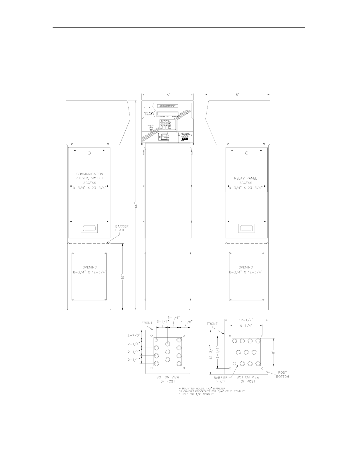
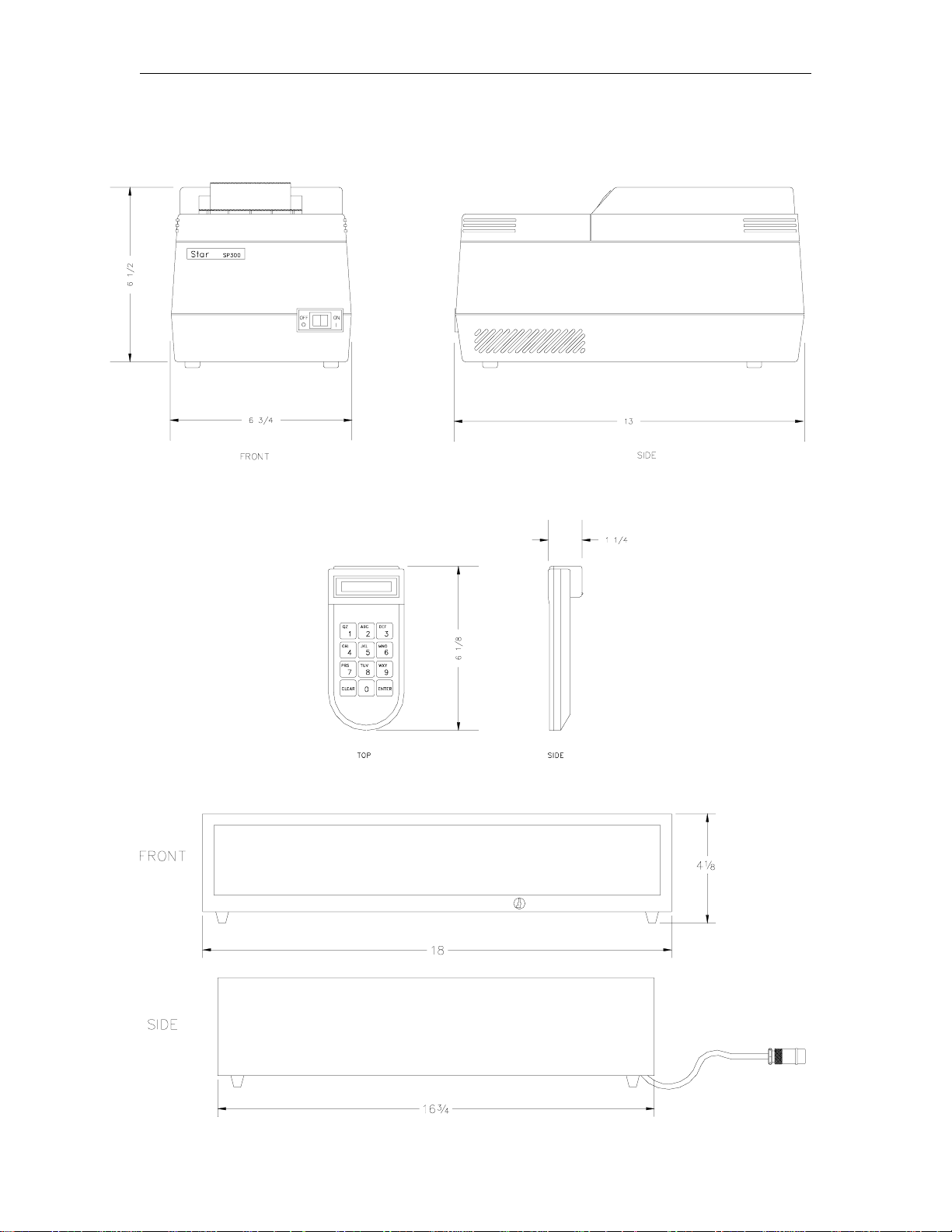
ISLANDER WITH STANDARD POST OR ISLAND-MOUNT STANDALONE
PUMP CONTROL UNIT
NOTE: Drawing shows standard Islander II unit. Island-Mount Standalone unit has the same
footprint, but does not have a head. Pedestal height is 48 inches.
2-2 03/07/03
Page 14
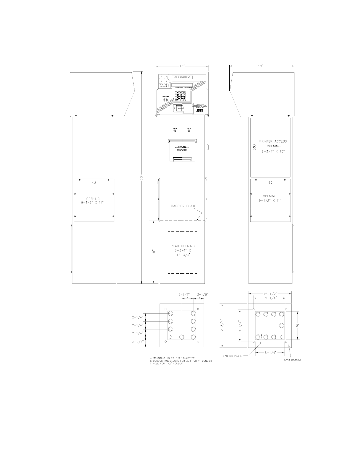
System Layout
ISLANDER WITH RECEIPT PRINTER POST
03/07/03 2-3
Page 15

CFN Series System
PUMP CONTROL UNIT (PCU) (OPTIONAL)
Description
The pump control unit (PCU) controls most mechanical pumps and some electronic pumps. The
unit is controlled by a microprocessor and communicates to the Islander via the RS-485 loop.
Each pump control unit can control up to four pumps or remote dispensers.
Hardware features include a battery backup for Weights and Measures requirements, three solid
state relays for each pump or remote dispenser (slow flow, fast flow and pump), manual override
switches, and diagnostic capabilities. Field wiring connections are made to the unit via easy-towire terminal blocks.
Pump control units, can be accommodated within the pedestal of the Islander (a standard pedestal
can accommodate two pump control units, a receipt printer pedestal can accommodate only one),
can be remote from the Islander (wall-mount), or can be a standalone unit located on the island.
Location
The pedestal version of the pump control unit is located within the Islander. The wall mount
version of the pump control unit must be located in an area protected from direct contact with
weather. The standalone version is located on the island. Do not install over a hazardous
location. All pump control units are designed for an operating temperature of -40
a relative humidity of 2% to 99% non-condensing.
o
F to 104oF with
2-4 03/07/03
Page 16
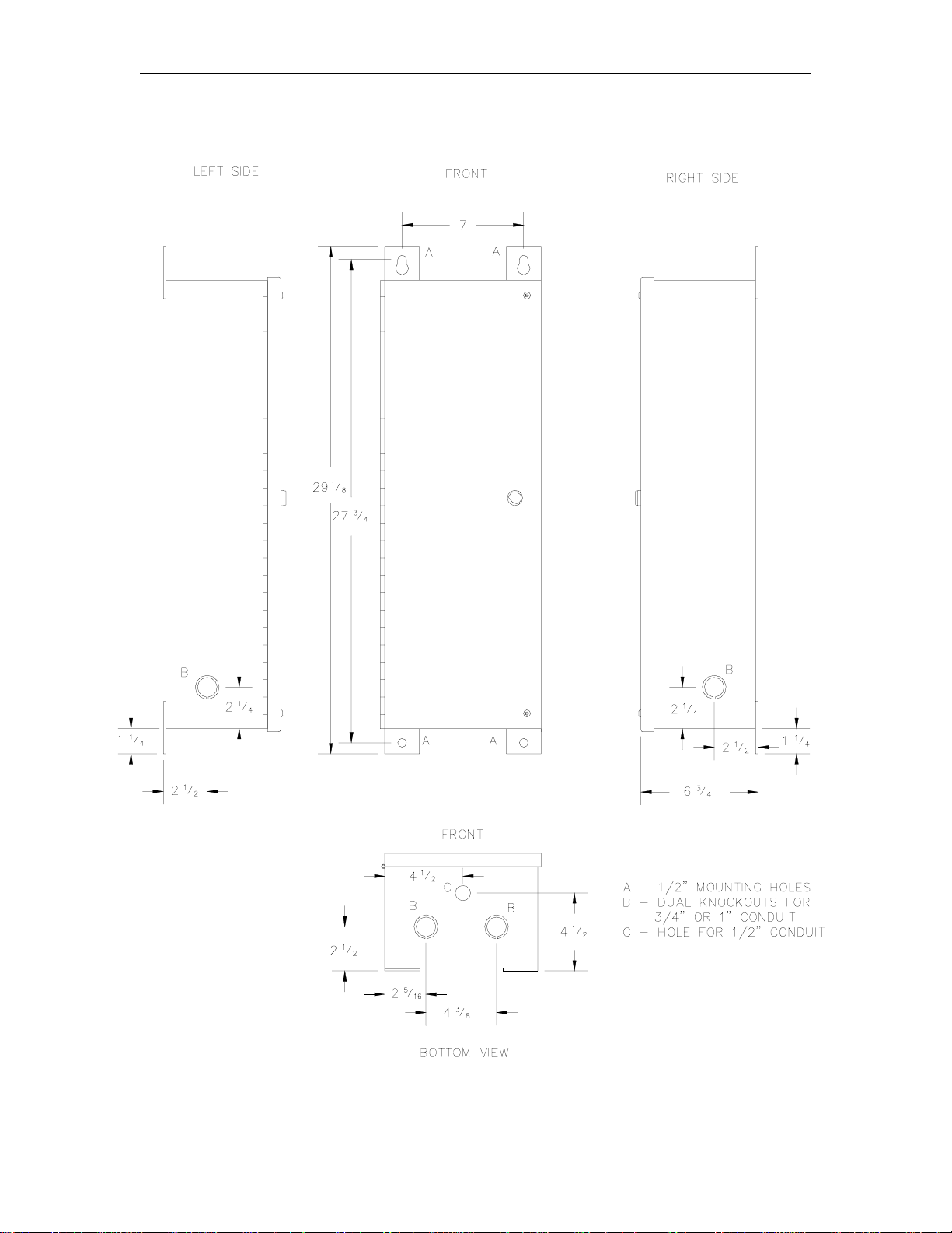
System Layout
WALL-MOUNT PUMP CONTROL UNIT (PCU) DIMENSIONS
03/07/03 2-5
Page 17

CFN Series System
CONSOLE (OPTIONAL)
Description
The Checkpoint console is used in retail applications to initiate and monitor sales at the Islander.
The unit is controlled by a microprocessor and communicates to the Islander via a direct RS-485
connection that requires an RS-485 junction box. The RS-485 junction box provides a means for
hard-wire connection while incorporating protection circuitry to prevent electrostatic sur ges (which
may occur on the field wiring) from reaching the console.
Each Checkpoint console can control up to 16 pumps or remote dispensers. A 20-character
alphanumeric display along with pump status LEDs are used to provide the operator with current
information regarding the site. Full-travel keys are used in the operation of the unit. An ABA
Track 2 magnetic stripe reader is provided for use in reading magnetic stripe cards for credit or
club card purchases.
An optional standalone receipt printer, a PIN (personal identification number) pad, a cash drawer ,
and a customer display are available for use with the console. The optional standalone receipt
printer is used for generating receipts in the building where the console is located. T he optional
PIN pad can be used to allow customers to secretly enter their PINs for console transactions. The
optional cash drawer is used for storage of cash at the site. The customer display allows you to
display console sales so they are visible to the customer.
Location
The console and optional equipment should be located in an office-type environment. The unit
must be located in an area protected fr om direct contact with the weather. Do not install over a
hazardous location. The unit is designed for an operating temperature range of 4
a relative humidity of 5% to 95% non-condensing. The operative temperature range for the
optional standalone receipt printer is 40
o
F to 104oF.
You can locate the console in a location up to 1000 feet away from the Islander. The RS-485
junction box must be located within eight feet of the console. See Console Wiring in Section 3.
o
F to 120oF with
2-6 03/07/03
Page 18
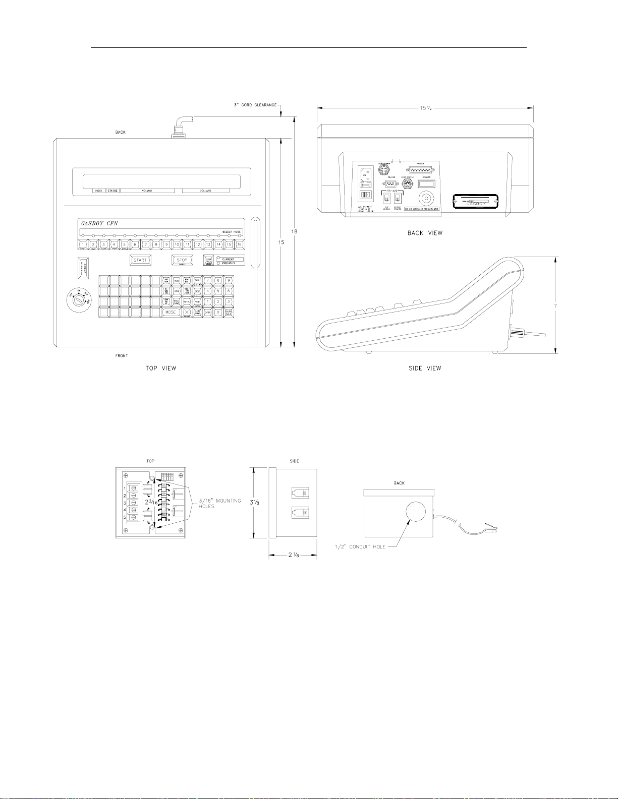
System Layout
CONSOLE
RS-485 JUNCTION BOX
03/07/03 2-7
Page 19
CFN Series System
CONSOLE OPTIONS
Standalone Receipt Printer
PIN Pad
Cash Drawer
2-8 03/07/03
Page 20
System Layout
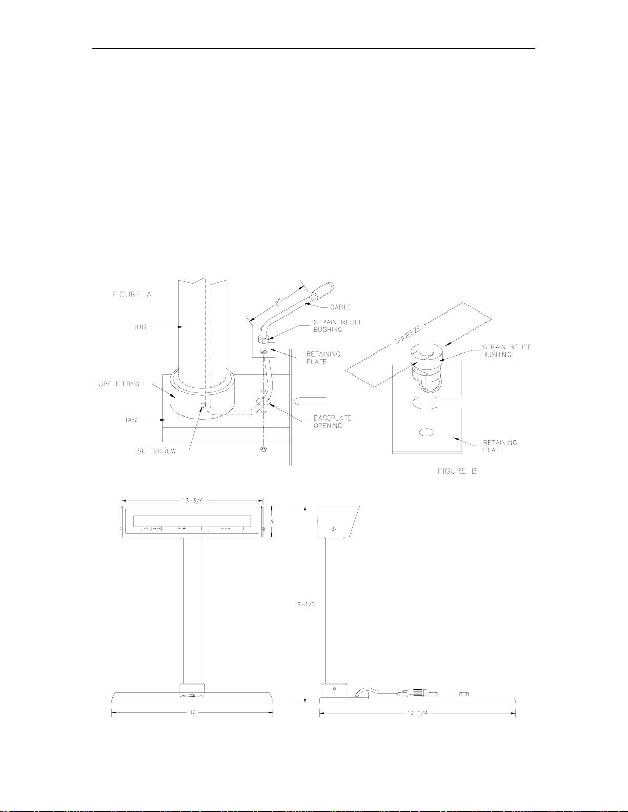
CUSTOMER DISPLAY (OPTIONAL)
Install the customer display as follows:
1. Remove the protective tape holding the connecting cable to the tube.
2. Thread the connecting cable from the tube down through the tube fitting in the base, under
the base and up through the opening in the base plate (Figure A). Be careful not to drop
display.
3. Install the tube in the tube fitting, position the display, and tighten the set screw in the tube
fitting.
4. Take the strain relief bushing and, using pliers, squeeze the bushing onto the wire. Snap the
bushing into the retaining plate (Figure B).
5. Screw the retaining plate to the base as shown in Figure A.
03/07/03 2-9
Page 21

CFN Series System
CRT/PRINTER (OPTIONAL)
Description
The CRT terminal is used for communication to and from the Islander. A CRT/printer combination
can be used as a logger for providing hard-copy printouts of action at the site or as an
interrogation device to extract information from the system via the system’s commands. A CRT
can be directly connected to the Islander, connected via short haul modems, or connected via
telephone modems.
Location
The CRT/printer should be located in a clean, office-type environment. Do not install over a
hazardous location. CRT/printer combinations supplied by GASBOY have an operating
temperature range of 32
o
F to 104oF, 10% to 95% relative humidity, non-condensing. Locating the
CRT/printer in a dirty environment may cause premature failures.
MODEMS (OPTIONAL)
Description
There are two types of modems (internal and external) that can be used for communication to the
Islander where distance or conditions will not permit direct connection to the unit. When an
internal modem is installed, remote port communication is routed through the modem in place of
being wired at the terminal block in the post. See Section 3, Phone Modems for details. Modems
to be used for dial-out to a bank network require a dedicated phone line.
Location
When an external modem is used with the system, it is recommended the modem be located in an
office-type environment. However, if this is not possible, it should be housed in a protective
enclosure. Do not install over a hazardous location. External modems supplied by GASBOY have
an operating temperature range of 32
o
F to 104oF.
When ordered, the internal modem is mounted inside the Islander at the factory. Power for the
modem is supplied by the Islander.
POWER CONDITIONER (OPTIONAL)
Description
A Listed power conditioner should be used when there is an unstable source of power. Poor
power conditions are a key cause to system malfunction or failure. When used, the power
conditioner helps provide clean power to the Islander and other CFN devices. The power
conditioner provides transient and common mode protection for the CFN system, although it
cannot totally compensate for extremely poor power conditions.
Location
The power conditioner should be located near (within 50 feet of) the Islander, but not in or above a
hazardous area. It must be located in an area protected from direct contact with weather (typically
near the system circuit breakers). The unit is designed for an operating temperature range of 0
o
to 104
F.
o
F
2-10 03/07/03
Page 22
System Layout
CONDUIT REQUIREMENTS
The conduit requirements outlined in this section are relevant to all components making up the
GASBOY system including, but not limited to, CFN system units, pumps, remote dispensers,
submersible pumps, submersible starter relays and the circuit breaker panels. The GASBOY
Warranty will not apply to any system deviating from the requirements outlined in this section.
All wiring and conduit runs must conform with all building/fire codes, all Federal, State, and Local
codes, National Electrical Code, (NFPA 70), NFPA 30, and Automotive and Marine Service
Station Code (NFPA 30A) codes and regulations. Canadian users must also comply with the
Canadian Electrical Code.
All wiring (AC and DC) connecting the different components of the CFN System and all
communication equipment signal wires must be installed underground in threaded, rigid, metal
conduit. PVC IS NOT ACCEPTABLE. It is recommended that high voltage AC power wires be
installed in separate conduit from the low voltage DC signal wires. However, if AC and DC wires
share conduit, DC wiring must use the cable specified in Section 3, Communication
Requirements (RS-485), Short Haul Modems (RS-422), and Section 4, Pulser Wiring and
Configuration. When AC and RS-485 or RS-422 wires are combined in the same conduit, only
AC wires for the system and pumps may be in that conduit.
All conduit must be connected to the CFN components through the holes and knockouts provided
by the factory. Do not make any other holes in these units. If alternate holes are required, contact
GASBOY for approval first.
Use the charts below as a guideline to determine the proper conduit sizes for the GASBO Y CFN
Series system. When planning the orientation of the wiring runs, follow the applicable GASBOY
wiring diagram and consider the layout of the components at the site. Long runs or a large
number of bends may require you to increase conduit size over what is listed.
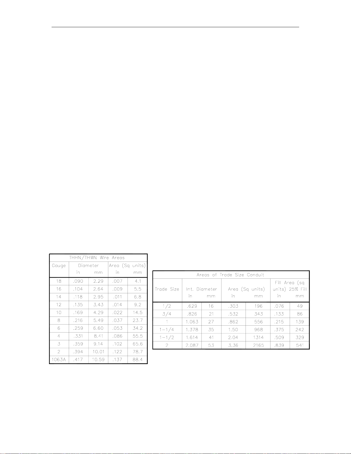
To determine conduit size needed, use the THHN/THWN Wire Areas table (left) to find the area
for each wire gauge. Add up all wire areas. Use the Areas of Tr ade Size Conduit Table (right) to
select the smallest number in the 25% fill area (based on NEC 501-1) that comes closest without
exceeding the total wire area.
03/07/03 2-11
Page 23

CFN Series System
CONDUIT LAYOUT/INSTALLATION SPECIFICATIONS
1. All wiring is to be installed and used in accordance with all building/fire codes, all Federal,
State, and Local codes, National Electrical Code (NFPA 70), NFPA 30, and Automotive and
Marine Service Station Code (NFPA 30A) codes and regulations. Canadian users must also
comply with the Canadian Electrical Code.
2. All peripher al equipment connected to the RS-232 ports must be Listed, have an Electronics
Industrial Association (EIA) standard RS-232 communications protocol and not be installed
over a hazardous location.
3. Power for the system components, data terminal, and modem must come from a separ ate
dedicated circuit breaker rated at no less than 10 AMPS.
4. All conduit must be metal to provide the necessary shielding.
5. All conduit must be run underground, not overhead.
6. DC pulser and DC RS-485 and RS- 422 communication wires can be combined in the same
conduit. It is recommended that the DC pulser, RS-485 and/or RS-422 wiring be in a
separate metal conduit from any AC wires. However, the DC pulser, RS-485 and/or RS-422
wires can share conduit with AC wires if shielded cable is used as specified in Section 3,
Communication Requirements (RS-485), Short Haul Modems (RS-422), and/or Section
4, Pulser Wiring and Configuration.
7. Use the wire size chart (Table 4-1) to determine the wire gauge.
8. Use the conduit size char ts to determine the size according to the number of wires and wire
gauge.
9. RS-232 communication must not exceed 100 feet. RS- 232 communication wires must be in
a metal conduit separate from any AC wires.
10. For communication distances exceeding 100 feet, you must use a GASBOY short haul
modem.
11. In submersible applications, starter relays are always recommended; however, the system
can directly drive motors up to 3/4 HP at 120/240 VAC or 1-1/2 HP at 240 VAC.
12. Suction pumps over 3/4 HP at 120/240 VAC or 1-1/2 HP at 240 VAC must use a starter relay.
Wire the starter relay in place of the motor in the applicable pump wiring drawing.
13. A minimum distance of 18 inches must be maintained between the Islander post and any of
the pumps/remote dispensers.
14. Disregard the submersible pump in the drawing if the hose outlets are suction pumps.
15. Consult the applicable section of this manual for specific system installation requirements.
16. When used with Fuel Point, an extra dedicated junction box is supplied to be installed in the
pump/dispenser. A separate dedicated conduit is to be run between the junction box and the
Fuel Point Reader. Consult the Fuel Point Reader Installation Manual C35628 for details.
2-12 03/07/03
Page 24
System Layout
CONDUIT LAYOUT-PUMP CONTROL POST
Mechanical Hose Outlets
03/07/03 2-13
Page 25
CFN Series System
CONDUIT LAYOUT-ISLAND-MOUNT STANDALONE PUMP CONTROL
Mechanical Hose Outlets
2-14 03/07/03
Page 26

System Layout
CONDUIT LAYOUT-WALL MOUNT PUMP CONTROL
Mechanical Hose Outlets
03/07/03 2-15
Page 27

CFN Series System
CONDUIT LAYOUT-GASBOY ELECTRONIC PUMPS/REMOTE DISPENSERS
Electronic Hose Outlets
2-16 03/07/03
Page 28

Section 3
SYSTEM COMPONENTS WIRING
GENERAL WIRING PRECAUTIONS
The quality of the electrical installation is a major factor in maintaining proper safety levels and
providing trouble-free operation of your GASBOY CFN System. To ensur e a quality installation,
follow these rules:
1. All wiring is to be installed and used in accordance with all building/fire codes, all Federal,
State, and Local codes, National Electrical Code (NFPA 70), NFPA 30, and Automotive and
Marine Service Station Code (NFPA 30A) codes and regulations. Canadian users must also
comply with the Canadian Electrical Code. Wiring must also conform to the wiring diagram
supplied with the pump/remote dispenser.
2. Use approved conduit and insulated gasoline- and oil-resistant wiring of the proper size.
3. Wire connections must be tightly spliced and secured with a wire nut; close off the open end
of the wire nut with electrical tape.
4. Install an emergency power cutoff. In addition to circuit breaker requirements of NFPA 70,
NFPA 30, NFPA 30A, and the Canadian Electrical Code (Canadian users only), a single
control which simultaneously removes AC power from all site dispensing equipment is
recommended. This control must be r eadily accessible, clearly labeled, and in accordance
with all local codes.
In a fuel management system application, the DISABLE PUMPS button on the Islander
and/or the DISABLE PUMPS and STOP keys on the console do not remove AC power from
equipment and under certain conditions, will not stop product flow.
In order to provide the highest level of safety to you, your employees, and customers, we
recommend that all employees be trained as to the location and procedure for turning off
power to the entire system.
To reduce the risk of electrical shock when servicing, turn off all power to the pump/remote
dispenser. In submersible pump applications, turn off all power to the submer sible pump and
any other dispensers which use that submersible pump. AC power can feed back into a shutoff dispenser when dispensers share a common submersible pump or starter relay.
Pour réduire le risque de choc électrique lors de l'entretien/révision, coupez totalement le
courant à la pompe/distributeur. Dans les applications de pompe immersible, coupez
totalement le courant à la pompe immersible et tous autres distributeurs qui utilisent la
pompe immersible. Le courant alternatif peut alimenter de nouveau un distributeur à l'arrêt
quand les distributeurs partagent une pompe immersible commune ou un relais de
démarrage.
WARNING
AVERTISSEMENT
03/07/03 3-1
Page 29

CFN Series System
POWER REQUIREMENTS
System/Peripheral Equipment
AC power for the CFN system components, data terminal, and exter nal modem must come from a
separate, dedicated circuit breaker. No other equipment, including the system’s pumps or remote
dispensers, may be powered from this breaker. Whenever possible, one breaker should be used
to supply the CFN system components, data terminal, and modem. However, it is acceptable to
supply the power to the different CFN system components and accessories from multiple
breakers within the same breaker panel and the same phase of power. When necessary,
power for the data terminal or modem may be supplied from a separate, dedicated breaker
located in a different breaker panel.
The system requires 120 VAC +
the use of a power conditioner. See Section 2, Power Conditioner for installation information.
Proper system grounding is an extremely important part of the system installation. As with the AC
power, the grounds for all CFN system components should return to the same breaker panel. This
helps to assure a common ground throughout the system which is necessary for protection of the
RS-485 data loop circuitry. Grounds for all system devices should be wired to the breaker panel
ground bus bar which in turn should be grounded to a gr ound rod. A conduit ground does not
provide a sufficient ground. It is recommended that the neutral and ground bus bars be bonded
together when it is not prohibited by local codes.
10% 47-63 HZ for power. An unstable power source may require
WIRE SIZE
The AC wire size for power of the CFN system components must be 14 AWG or larger. This
gauge of wire will be sufficient for runs of up to 300 feet from the breaker panel to the system.
Components with distances over 300 feet must use 12 AWG wire or larger. All wire should be
stranded.
The specifications for the RS-485 data loop and RS-232 and RS-422 communication wire/cable
size can be found in Communication Requirements (RS-485) and/or Short Haul Modems (RS-
422) later in this section.
COMMUNICATION REQUIREMENTS
The CFN System utilizes RS-485, RS-232, and RS-422 modes of communication for
communicating to other CFN system components and peripheral equipment. The Islander has six
ports: two are RS-485 and are dedicated to communicating with other CFN components; the other
four can be individually set up for use with a terminal, modem, or PC and can be RS-232 or RS-
422. Phone line (modem) communication may also be used when remote communication to the
site is desired. In cases where an Islander internal modem is used, the port connected to the
internal modem is not available for external communication wiring. The specific requirements for
each of these modes of communication are listed below.
RS-485
RS-485 wiring is used for communication between the CFN system components. This
communication takes place over the RS-485 modular cables provided with the system
components and the RS-485 data loop field wiring. The following installation requirements must
be followed when installing the CFN RS-485 communication lines:
3-2 03/07/03
Page 30

System Components Wiring
1. All wiring is to be installed and used in accordance with all building/fire codes, all Federal,
State, and Local codes, National Electrical Code (NFPA 70), NFPA 30, and Automotive and
Marine Service Station Code (NFPA 30A) codes and regulations. Canadian users must also
comply with the Canadian Electrical Code.
2. Cable: Twisted pair shielded cable is highly recommended for RS-485 wiring and is required
for distances over 100 feet. Although it is recommended that wires be run in a conduit
separate from AC wires, they can be combined in the same conduit with AC wires providing
UL-Listed cable with the following specifications is used:
Conductor: 18 AWG stranded wire. 2 twisted-pairs.
Shield: Foil-wrapped 100% coverage and/or tinned copper braid 90% coverage
Drain Wire: Stranded, tinned copper, 20 AWG or larger/or braided shield
Voltage Rating: Maximum operating voltage of 600V
Environmental: Gas- and oil-resistant; suitable for wet or dry locations.
GASBOY can supply Belden 1063A (P/N C09655) which is a UL-Listed, 4-conductor cable
that meets the requirements listed above. NOTE: Belden 1063A is UL-Listed but not CSA
listed.
Cable with a voltage rating of less than 600V must be installed in a conduit separate from all
AC wires.
3. Conduit: When using the recommended shielded, twisted-pair cable described above, the
cable can be run with AC wires in metal conduit. The shield drain wire must be connected to
the system AC ground. Only AC wir es for the system and pumps can be installed in the AC
conduit. Do not run the cable outdoors without the use of metal conduit. Do not run this
cable overhead, outdoors.
The cable can be run indoors without the use of metal conduit. The shield drain wire must be
connected to the system AC ground.
If using cable other than that recommended above, the RS-485 field wires must be installed
in a metal conduit separate from any AC wires.
4. Distance: The following distances must be adhered to when installing the RS-485 field
wiring.
● The distance from the Islander to the farthest CFN component is limited to 1000 feet.
● The total length of the RS-485 field wiring to all the CFN components cannot exceed
1500 feet.
5. RS-485 Modular Cable: The RS-485 modular cables required are supplied with the system.
These cables are not compatible with standard phone cables that can be obtained from other
sources.
GASBOY-supplied cables are eight feet long. If you need to connect a CFN component with
a modular connector (i.e., console) to the Islander, you must use an RS-485 junction box to
connect the device to the RS-485 communication wiring.
6. Connections: See the System Components Wiring Diagram later in this section for proper
connection of the RS-485 field wiring to the CFN system components.
03/07/03 3-3
Page 31

CFN Series System
RS-232
RS-232 wiring can be used for communication between the CFN Islander and EIA RS-232
compatible peripheral devices (CRT/printer, modem, etc.). The remote end of the wiring can be
terminated with either an RS-232D connector or a GASBOY termination box. You must follow
these installation requirements when installing the CFN RS-232 communication lines:
1. All peripheral equipment connected to the RS-232 ports must be UL-listed, have an
Electronics Industry Association (EIA) standard RS-232 communication pr otocol and not be
installed over a hazardous location.
2. Distance: The following distances must be adhered to when installing the RS-232
communication lines:
● 1 - 100 feet: RS-232 can be directly connected to a peripheral device.
● 101 - 1500 feet: RS-422 and GASBOY shor t haul modems (SHM) are requir ed. See Short
Haul Modems later in this section.
3. Conduit: All direct connect RS-232 cables over 15 feet must be in a metal conduit separate
from any AC wires. For conduit requirements of short haul modems, see the installation
sheet that applies to the device being used.
4. Cables: RS-232 cables can either be purchased from GASBOY or made by the installer.
The type of cable needed will vary according to the devices it connects. When making
cables, wire used must be stranded, not solid core and may be 18 to 22 gauge.
RS-422
For guidelines and restrictions on RS-422 wiring, see Short Haul Modems (RS-422) later in this
section.
3-4 03/07/03
Page 32

System Components Wiring
RS-232 CABLES
RS-232 11 Cable (P/N C04549 8-foot M/M)
RS-232 DTE Cross Cable (P/N C07514)
Termination Box
A termination box can be purchased from GASBOY and provides the installer with an easy- to- wir e
terminal block connected to the proper pins on an RS-232D female connector. The terminal block
will accept up to 18 AWG wire.
03/07/03 3-5
Page 33

CFN Series System
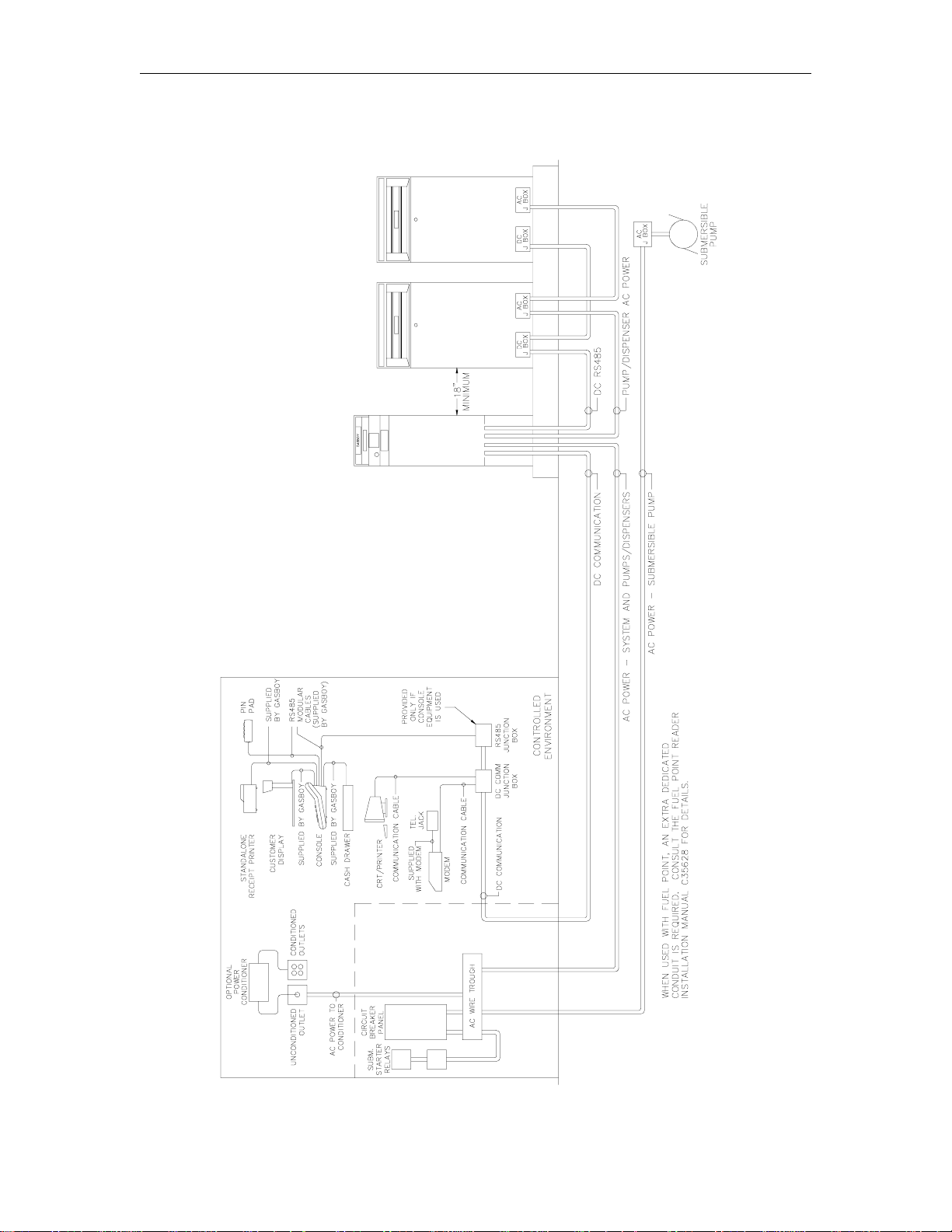
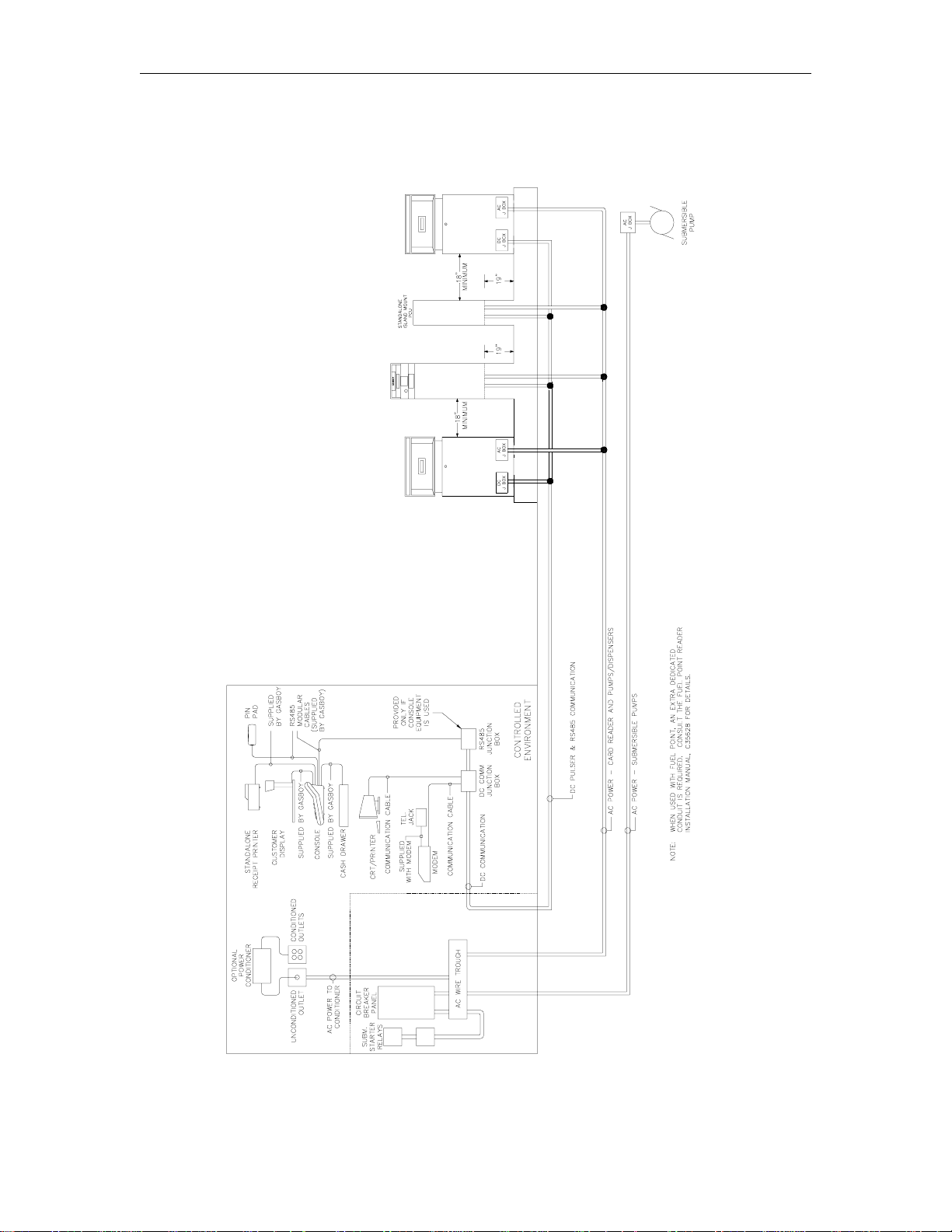
SYSTEM COMPONENTS WIRING DIAGRAM
NOTES:
1. All wiring is to be installed and used in accordance with all building/fire codes, all Federal,
State, and Local codes, National Electrical Code (NFPA 70), NFPA 30, and Automotive and
Marine Service Station Code (NFPA 30A) codes and regulations. Canadian users must also
comply with the Canadian Electrical Code. Wiring must also conform to the wiring diagram
supplied with the pump/remote dispenser.
2. All peripheral equipment connected to the RS-232 ports must be UL-listed, have an
Electronics Industry Association (EIA) standard RS-232 communications protocol and not be
installed over a hazardous location.
3-6 03/07/03
Page 34

System Components Wiring
3. The above wiring diagram illustrates a CFN System with every component to indicate how
they are interconnected. Components that are not a part of your system should be ignored.
4. When using shielded cable for the RS-485 communication wiring, ground the shield to the AC
ground used for the system components (on one end only).
5. CFN island card readers (ICR’s) are interchangeable with satellite Islanders in your
configuration.
6. Consult the applicable section of this manual for specific system installation requirements.
03/07/03 3-7
Page 35

CFN Series System
CHECKPOINT CONSOLE WIRING
The Checkpoint console(s) can be located up to 1000 feet from the Islander. You must use an
RS-485 junction box and wire the site as shown below. Remember to mount the junction box
within eight feet of the console as the supplied cables are only eight feet long.
MULTIPLE CHECKPOINT CONSOLE WIRING
The following diagram illustrates how to connect multiple Checkpoint consoles. All wiring must be
installed according to the RS-232 and RS-485 wiring specifications discussed previously.
3-8 03/07/03
Page 36

System Components Wiring
PORT COMMUNICATION WIRING
The following diagrams show the pin-to-pin layout of the possible wiring schemes for the Islander
ports. Each port may be wired for any of the wiring schemes provided the installation
requirements are met as outlined at the beginning of this section in the Communication
Requirements. In the drawings below, the LOCAL terminal block (TB3) is connected to Port 0 of
the Islander II.
NOTE: To insure the necessary signals and proper operation, external modems used in dial-out
or bank network applications must use the remote or Port 2 terminal block (TB4).
Local Port Wiring
RS-232 - D Connector
RS-232 - GASBOY Termination Box
RS-422 - GASBOY Short Haul Modem
03/07/03 3-9
Page 37

CFN Series System
Remote Port Wiring
In the drawings below, the remote terminal block (TB4) is connected to port 2 of the site controller.
Port 3 terminal block (TB6) is a five-position terminal block. The wiring to TB6 will still be the
same as that shown for the first five positions of TB4.
RS-232 - D Connector
RS-232 - GASBOY Termination Box
3-10 03/07/03
Page 38

System Components Wiring
RS-422 - GASBOY Short Haul Modem
03/07/03 3-11
Page 39

CFN Series System
SHORT HAUL MODEMS (RS-422)
A GASBOY short haul modem and the appropriate interconnect cable must be used when the RS422 communication mode is being used to communicate to one of the ports of the CFN Islander.
It should be used for distances between 100 and 1500 feet. It can be used for distances under
100 feet in place of RS-232 wiring. One SHM is required at the remote end of the communication
wiring. See Port Communication Wiring earlier in this section for local and remote wiring
diagrams.
Installation Requirements
1. All wiring is to be installed and used in accordance with all building/fire codes, all Federal,
State, and Local codes, National Electrical Code (NFPA 70), NFPA 30, and Automotive and
Marine Service Station Code (NFPA 30A) codes and regulations. Wiring must also conform
to the wiring diagram supplied with the pump/remote dispenser. Canadian users must also
comply with the Canadian Electrical Code.
2. Power: The AC power for the short haul modem should come from the same breaker that
supplies the peripheral device or the system.
3. Cable: Twisted pair shielded cable is highly recommended for RS-422 wiring. Although it is
recommended that wires be run in a conduit separate from AC wires, they can be combined
in the same conduit with AC wires providing UL-Listed cable with the following specifications
is used:
Conductor: 18 AWG stranded wire. 2 twisted-pairs.
Shield: Foil-wrapped 100% coverage and/or tinned copper braid 90% coverage
Drain Wire: Stranded, tinned copper, 20 AWG or larger/or braided shield
Voltage Rating: Maximum operating voltage of 600V
Environmental: Gas- and oil-resistant; suitable for wet or dry locations.
GASBOY can supply Belden 1063A (P/N C09655) which is a UL-Listed, 4-conductor cable
that meets the requirements listed above. NOTE: Belden 1063A is UL-Listed but not CSA
listed.
Cable with a voltage rating of less than 600V must be installed in a conduit separate from all
AC wires.
These modems must be connected with private lines and will not work if connected into a
telephone network.
4. Conduit: When using the recommended shielded twisted-pair cable described previously,
RS-422 wires can be run with AC wires in metal conduit. The shield drain wire must be
connected to the system AC ground. Only AC wires for the system and pumps can be
installed in the AC conduit. Do not run the cable outdoors without the use of metal conduit.
Do not run this cable overhead, outdoors.
The cable can be r un indoor s without the use of metal conduit. The shield dr ain wire must be
connected to the system AC ground.
If using cable other than that recommended previously, the RS-422 field wires must be
installed in a metal conduit separate from any AC wires.
5. Distance: The maximum field wiring cable length is not to exceed 1500 feet.
3-12 03/07/03
Page 40

System Components Wiring
WIRING FOR A LINK CRT TERMINAL AND OKIDATA PRINTER
The following diagram shows the connections between the Islander port and the Link CRT
terminal and Okidata printer.
PHONE MODEMS
External Modems
The type of phone line required for communication via an external modem is contingent upon the
type of modem used and the method of communication desired. Consult the manual that comes
with the modem for specific requirements.
Internal Modem
The Islander is available with an optional internal modem. When this modem is installed, remote
port communication is routed through the modem in place of being wired at the terminal block in
the post. The phone line for the internal modem must not be installed in the DC conduit. Check
with your local phone company for proper installation of the phone line.
The 2400 baud modem is designed for 300, 1200, or 2400 baud, full duplex, asynchronous
communication. The modem is mounted inside the Islander at the factor y. Power for the modem
is supplied by the Islander.
The modem is designed to meet or exceed the direct connection registration requirements of the
FCC rules. This means the modem will connect directly with a jack supplied by the phone
company. The customer is required to order this jack and have it installed. To order this
equipment from the phone company, specify:
1. Any one of the following jacks: RJ11C or RJ41S, OR RJ45S.
2. The registration number of 6BHUSA-24793-DT-E.
3. The data transmission rate of 300 baud, 1200 baud, or 2400 baud.
4. The Bell equivalent of 103J/212A.
03/07/03 3-13
Page 41

CFN Series System
WIRING FOR A TANK MONITORING SYSTEM
The following diagrams show the wiring schemes for connecting the Islander to a tank monitoring
system. All wiring must be installed according to the RS-485, RS-232 and RS-422 wiring
specifications discussed previously. Consult manufacturer’s documentation for installation
instructions before connecting a tank gauge to your CFN system. For EECO monitors, use a
C07476 cable in place of the C04549.
RS-485 Loop Connection
RS-232 D Connector
RS-232 GASBOY Termination Box
RS-422 GASBOY Short Haul Modem
3-14 03/07/03
Page 42

System Components Wiring
GATE CONTROLLER WIRING USING GATE READER
The CFN system can activate a gate controller by using the CFN Gate Island Reader or Gate
Satellite Reader. Either of these Gate Readers allows activation by card, Fuel Point, or ter minal
command, but not via console or POS terminal.
1. The CFN Gate ICR can directly switch power to a gate controller. The maximum ratings of the
switched power is not to exceed 5A @ 30VDC or 1/8HP @ 120VAC. If the gate controller
switch control exceeds those ratings, an auxiliary relay must be installed to handle the load.
The auxiliary relay coil is not to exceed the ratings mentioned above.
2. The CFN system allows a loadable timeout value up to two minutes during which time the
relays are energized. The selected time depends on the gate controller manufacturer’s
specification.
3. Instead of a timed closure, the system also allows the relays to stay energized indefinitely until
a signal comes back to turn them off. The signal is 120VAC only, and is connected to the I/O
Board’s Switch Detect connector.
03/07/03 3-15
Page 43

Page 44

Section 4
PUMP/REMOTE DISPENSER WIRING
WIRING PRECAUTIONS
The quality of the electrical installation is a major factor in maintaining proper safety levels and
providing trouble-free operation of your GASBOY CFN System. To ensur e a quality installation,
follow these rules:
1. All wiring is to be installed and used in accordance with all building/fire codes, all Federal,
State, and Local codes, National Electrical Code (NFPA 70), NFPA 30, and Automotive and
Marine Service Station Code (NFPA 30A) codes and regulations. Canadian users must also
comply with the Canadian Electrical Code. Wiring must also conform to the wiring diagram
supplied with the pump/remote dispenser.
2. Use approved conduit and insulated gasoline- and oil-resistant wiring of the proper size.
3. Wire connections must be tightly spliced and secured with a wire nut; close off the open end
of the wire nut with electrical tape.
4. The line to the motor should be on a separate circuit and fused to carry 20 to 30 AMPS
depending on the motor size and/or the voltage setting.
5. Install an emergency power cutoff. In addition to circuit breaker requirements of NFPA 70,
NFPA 30A, and the Canadian Electrical Code (Canadian users only), a single control which
simultaneously removes AC power from all site dispensing equipment is recommended. This
control must be readily accessible, clearly labeled, and in accordance with all local codes.
In a fuel management system application, the DISABLE PUMPS button on the Islander
and/or the DISABLE PUMPS and STOP keys on the console do not remove AC power from
equipment and under certain conditions, will not stop product flow.
In order to provide the highest level of safety to you, your employees, and customers, we
recommend that all employees be trained as to the location and procedure for turning off
power to the entire system.
To reduce the risk of electrical shock when servicing, turn off all power to the pump/remote
dispenser. In submersible pump applications, turn off all power to the submer sible pump and
any other remote dispensers which use that submersible pump. AC power can feed back
into a shut-off remote dispenser when dispensers share a common submersible pump or
starter relay.
Pour réduire le risque de choc électrique lors de l'entretien/révision, coupez totalement le
courant à la pompe/distributeur. Dans les applications de pompe immersible, coupez
totalement le courant à la pompe immersible et tous autres distributeurs qui utilisent la
pompe immersible. Le courant alternatif peut alimenter de nouveau un distributeur à l'arrêt
quand les distributeurs partagent une pompe immersible commune ou un relais de
démarrage.
WARNING
AVERTISSEMENT
03/07/03 4-1
Page 45

CFN Series System
POWER REQUIREMENTS
Suction Pumps
The CFN pump control unit is capable of directly driving pump motors up to 3/4 HP at 120/240
VAC or 1-1/2 HP at 240 VAC. A starter relay must be used with pump motors exceeding these
limitations. A separate circuit breaker should be supplied for each pump to meet the current
requirements and to allow for isolated control with the circuit breaker panel in case of problems.
Remote Dispensers
The CFN pump control unit is capable of directly driving submersible pumps up to 3/4 HP at
120/240 VAC or 1-1/2 HP at 240 VAC. A remote dispenser with a submersible pump rated over
these limitations will require the use of a submersible starter relay. A separate circuit breaker
should be supplied for each remote dispenser in cases where it will directly drive the submersible
pump. Remote dispensers may be grouped together on a single breaker when the submersible
pump has its own breaker. It is recommended that no more than two remote dispensers be
powered from one breaker to maintain isolated control with the circuit breaker panel in case of
problems.
GASBOY 9800 Pumps/Remote Dispensers
GASBOY 9800 Series pumps and remote dispensers do not use the CFN Pump Control Unit.
They are wired as standalone units. Refer to the 9800 Pumps and Dispensers
Installation/Operation Manual, 035235 for wiring diagrams and instructions.
WIRE SIZE
Table 4-1 shows the required AC wire size for suction and submersible pumps based on the HP
rating of the pump motor and the distance from the circuit breaker to the pump/remote dispenser
for both 120 and 240 volt units. Use this table as a guide for selecting the proper size wire for
your installation. All wire should be stranded.
The wire size for the switch detect from the pump should be 14 AWG. The wire size for the
control lines of a remote dispenser should be 12 AWG. These contr ol lines are used to supply
power for the reset mechanism, solenoid valve, and submersible starter relay (when the
submersible pump is not directly powered by the remote dispenser). The wire size for DC pulsers
should be 18 AWG. This size exceeds the current requirements of the pulser and is primarily
used for its strength.
Table 4-1. Wire Size
4-2 03/07/03
Page 46

Pump/Remote Dispenser Wiring
WIRING ELECTRONIC OR MECHANICAL PUMPS
The remainder of this section shows wiring schematics for electronic and mechanical pumps. All
electronic and mechanical pumps must be installed according to the manufacturer’s instructions.
Depending on the type of electronic pump to which you are connecting, you may require additional
information. Refer to the Pump Interface Manual, C09146 or contact Gasboy Technical Service
for information on various pump interfaces.
Connection of Tokheim Pumps
The following diagrams show the interconnection for the Islander II and the Tokheim interface.
D Connector
GASBOY ISL/TOK Termination Box
03/07/03 4-3
Page 47

CFN Series System
Tokheim Splitter Cabling
NOTES:
1. Use a C05578 cable for connection to a single 67 or 98 Interface box. Use a C05876 cable
for connection to two 67 or 98 Interface boxes. Both cables include the Tokheim Splitter.
2. A Model 180 signal cable extension is available as an accessory from Tokheim. The
maximum distance of the combined cables and field wiring should not exceed 350 feet. The
maximum distance for a 98 Interface box is 250 feet.
3. Use part number C06694 for connection to three or more 98 Interface boxes. C06694 is the
combination of one C05878 cable, two C05577 cables and a Tokheim Splitter.
4. Communication for pumps 1-32 may be provided through port1 or 3 of the Islander II.
5. The second two 98 boxes must be connected to channel 2 of the splitter. Addr ess the third
98 box (first 98 box on channel 2) as pumps 1 to 8; address the fourth 98 box (second 98 box
on channel 2) as pumps 9 to 16.
4-4 03/07/03
Page 48

Pump/Remote Dispenser Wiring
Tokheim 162 Interface, Electronic Interface
Basic System
1 to 8 Hoses System consists of one Islander II, one computer module, and one C05578 cable
9 to 16 Hoses System consists of one Islander II, two computer modules, and one C05876 cable
17 to 24 Hoses System consists of one Islander II, three computer modules, and one C06694
25 to 32 Hoses System consists of one Islander II, four computer modules, and one C06694
and Tokheim Splitter combination.
and Tokheim Splitter combination.
cable and Tokheim Splitter combination.
cable and Tokheim Splitter combination.
NOTES:
1. All Tokheim equipment should be installed per Tokheim specifications.
2. Wiring trough, conduits, and wire are furnished by the installer.
3. A Model 180 signal cable extension is available as an accessory from Tokheim. The
maximum distance of the combined cables should not exceed 350 feet. The maximum
distance for a 94 or 98 interface box is 250 feet.
4. Communication for pumps 1-32 may be provided through port 1 or 3 of the Islander II.
5. The second two 98 boxes must be connected to channel 2 of the splitter. Addr ess the third
98 box (first 98 box on channel 2) as pumps 1 to 8; address the fourth 98 box (second 98 box
on channel 2) as pumps 9 to 16.
03/07/03 4-5
Page 49

CFN Series System
Tokheim 262 and 262A Interface, Electronic Interface
Basic System
1 to 16 Hoses System consists of one Islander II, one interface box, and one C05578 cable and
17 to 32 Hoses System consists of one Islander II, two interface boxes, and one C05876 cable
Tokheim Splitter combination.
and Tokheim Splitter combination.
NOTES:
1. All Tokheim equipment should be installed per Tokheim specifications.
2. Wiring trough, conduits, and wire are furnished by the installer.
3. A Model 180 signal cable extension is available as an accessory from Tokheim. The
maximum distance of the combined cables should not exceed 350 feet. The maximum
distance for a 94 or 98 interface box is 250 feet.
4. A Model 68 Box is recommended for emergency shut-off applications.
5. Communication for pumps 1-32 may be provided through port 1 or 3 of the Islander II.
4-6 03/07/03
Page 50

Pump/Remote Dispenser Wiring
Tokheim 330B, 333B-SA, TCS, and Premier Interface, Electronic Interface
Basic System
1 to 16 Hoses System consists of one Islander II, one interface box, and one C05578 cable and
17 to 32 Hoses System consists of one Islander II, two interface boxes, and one C05876 cable
Tokheim Splitter combination.
and Tokheim Splitter combination.
NOTES:
1. All Tokheim equipment should be installed per Tokheim specifications.
2. Wiring trough, conduits, and wire are furnished by the installer.
3. A Model 180 signal cable extension is available as an accessory from Tokheim. The
maximum distance of the combined cables should not exceed 350 feet. The maximum
distance for a 94 or 98 interface box is 250 feet.
4. A Model 68 Box is recommended for emergency shut-off applications.
5. Communication for pumps 1-32 may be provided through port 1 or 3 of the Islander II.
03/07/03 4-7
Page 51

CFN Series System
TERMINAL BLOCK ID
All mechanical pump/remote dispenser wiring for the CFN System is terminated in the pump
control unit. Terminal connectors should be used on stranded wire when connecting to the pump
power and power input terminal blocks of the system. Connections made to the smaller screw
terminal blocks (Pump Control I/O PCB Assembly) do not require terminal connectors. The wire to
these connectors must not be any larger than 14 AWG. This page and the following pages show
terminal block locations for the receipt printer pedestal, the standard pedestal (left and right views)
and the wall mount pump control unit.
Receipt Printer Pedestal
4-8 03/07/03
Page 52

Pump/Remote Dispenser Wiring
Standard Pedestal - Left Side
03/07/03 4-9
Page 53

CFN Series System
Standard Pedestal - Right Side
4-10 03/07/03
Page 54

Pump/Remote Dispenser Wiring
Wall Mount Pump Control Unit
03/07/03 4-11
Page 55

CFN Series System
CONTROL LINES
Descriptions of the control lines are provided to familiarize the installer with the control inputs and
outputs that are used to control a mechanical pump/remote dispenser. It is recommended the
installer read these descriptions to obtain a better working knowledge of the system in order to
guide him in planning the site wiring.
Grounding
To ensure proper operation of the equipment and provide the necessary safety factors, this unit
must be grounded. A ground wire (preferably green) must be connected between the unit’s AC
junction box ground lug and the main electrical service panel. One (1) ear th ground connection is
required per unit. A ground rod must be installed at the main electrical panel in accordance with
the National Electrical Code. This ground rod is to be a solid, corrosion-resistant conductor. It
should be properly tied into the ground bus strip of the panel. We recommend the neutral and
ground bus strips be bonded together (unless prohibited by local codes).
Reset Motor Feed
This is a 120VAC input which is supplied through the pump handle switch to activate the reset
motor. This line should be switched through the CFN System and only be on when the
pump/remote dispenser is authorized or in manual mode. Without power supplied to this line, the
pump/remote dispenser will not reset when the pump handle is turned on. Two feed lines are
provided for twins. This feed is also connected to the input of one of the internal switches of the
electric reset. When the reset finishes its cycle, the 120VAC input to the switch will be passed
through as an output causing the solenoid valve (optional in some models) to open and the Reset
Complete line to indicate 120VAC.
NOTE: This line is also used to sense the closing of the pump handle for console operation. A
low current 120VAC is supplied through this line in order to sense the condition of the
handle. This low current voltage is not capable of driving the reset motor or oper ating a
solenoid valve.
Pump Motor Feed
This is a 120VAC input which is supplied to the input side of one of the internal switches of the
electric reset. This line should be switched through the CFN System and only be on when the
pump/remote dispenser is authorized or in manual mode. When the reset finishes its cycle, the
120VAC input to the switch is passed through as an output causing the pump motor to receive
power and begin running. Without power to this line, the unit would reset, but be unable to fuel.
Two feed lines are provided in twins which contain two motors. The gauge of this wire (and its
neutral wire) should be determined according to the size of the motor, the voltage at which the
motor will be powered (120VAC or 240VAC), and the distance from the breaker panel to the
pump. It is possible to combine the pump motor feeds for twins and supply them from one
breaker; however, the gauge of the wire must be adjusted to handle the load of two motors.
(NOTE: 240 VAC is developed across a motor when the other leg of the motor is connected to a
Phase 2 Feed.)
Neutral Feed
This is the AC current return line back to the breaker panel for all attached devices (pump motor,
reset motor, solenoid valves). The gauge of this wire must be equal to that of the pump motor
feed (suction pumps) or submersible feed (remote dispensers).
4-12 03/07/03
Page 56

Pump/Remote Dispenser Wiring
Submersible Feed, Submersible Drive
This is a 120VAC input which is supplied to the input side of one of the internal switches of the
electric reset. This line should be switched through the CFN System and only be on when the
pump/remote dispenser is authorized or in manual mode. When the reset finishes its cycle, the
120VAC input to the switch is passed through as an output (submersible drive) to dr ive a starter
relay or to directly drive a submersible motor up to 3/4 HP at 120/240 VAC or 1-1/2 HP at 240
VAC. Any submersible motor exceeding these limitations must use a starter relay. (NOTE: 240
VAC is developed across a motor when the other leg of the motor is connected to a Phase 2
Feed.)
Reset Complete (Switch Detect)/Slow Flow
This is a 120VAC output which is used to indicate the reset is complete and the pump/remote
dispenser is ready to dispense product. Two lines are provided for twins. This line should only be
used when monitoring of the pump/remote dispenser is desired (such as with a fuel management
system). This line must be capped when not in use. This line is connected to the slow flow stage
of the solenoid in the pump.
Fast Flow
This is a 120VAC input which controls the fast flow valve of the pump/remote dispenser (when a
slow/fast flow valve is available). If slow/fast flow control is not desired, this line should be tied to
the reset complete/slow flow line. This line should be switched through the CFN System and only
be on when the pump/remote dispenser is authorized and the pump/remote dispenser should be
in the fast flow mode. This line will also be switched on when the pump/r emote dispenser is in the
manual mode.
Light Feed
This is a 120VAC input required to power optional fluor escent lights that may be available in a
pump/remote dispenser. In a site configuration using multiple remote dispensers (or pumps), the
power for the lights of up to 8 units can be supplied by one breaker. The light feed is not
controlled by the CFN System.
Light Neutral
This is a return line for AC current from the lights to the breaker panel.
Phase 2 Feed
This is a hot feed which is the opposite phase of the pump motor feed. This line and the pump
motor feed are used for 240VAC motor applications.
Pulser
This supplies a DC output which is provided to indicate the quantity dispensed. This line must be
capped when not in use. DC pulser and DC RS-422 and RS-485 communication wires can be
combined in the same conduit. DC wires must be in separate metal conduit from AC wires unless
shielded cable is used as specified in Section 3, RS-485, Short Haul Modems (RS-422), and
Pulser Wiring and Configuration.
03/07/03 4-13
Page 57

CFN Series System
PULSER WIRING AND CONFIGURATION
Pulser wiring diagrams appear below. Pulser wiring requirements are detailed on the following
page.
4-14 03/07/03
Page 58

Pump/Remote Dispenser Wiring
Pulser Wiring Requirements
When installed in a separate DC conduit, 18 AWG wires are required for installation. Although it is
recommended that DC pulser wires be run in a conduit separate from AC wires, they can be
combined in the same conduit with AC wires providing UL-Listed cable with the following
specifications is used:
Conductor: 18 AWG stranded wire. Number of conductors to be determined by pulser
Shield: Foil-wrapped 100% coverage and/or tinned copper braid 90% coverage
Drain Wire: Stranded, tinned copper, 20 AWG or larger/or braided shield
Voltage Rating: Maximum operating voltage of 600V
Environmental: Gas- and oil-resistant; suitable for wet or dry locations.
GASBOY can supply Belden 1063A (P/N C09655) which is a UL-Listed, 4-conductor cable that
meets the requirements listed above. NOTE: Belden 1063A is UL-Listed but not CSA listed.
03/07/03 4-15
Page 59

CFN Series System
SINGLE SUCTION PUMP, V/R RESET
4-16 03/07/03
Page 60

Pump/Remote Dispenser Wiring
TWIN SUCTION PUMP, V/R RESET
03/07/03 4-17
Page 61

CFN Series System
TWIN SUCTION PUMP, SINGLE MOTOR, V/R RESET
4-18 03/07/03
Page 62

Pump/Remote Dispenser Wiring
SINGLE REMOTE DISPENSER, V/R RESET
03/07/03 4-19
Page 63

CFN Series System
TWIN REMOTE DISPENSER, V/R RESET
4-20 03/07/03
Page 64

Pump/Remote Dispenser Wiring
SINGLE SUCTION PUMP WITH CONSOLE, V/R RESET
03/07/03 4-21
Page 65

CFN Series System
TWIN SUCTION PUMP WITH CONSOLE, V/R RESET
4-22 03/07/03
Page 66

Pump/Remote Dispenser Wiring
TWIN SUCTION PUMP, SINGLE MOTOR WITH CONSOLE, V/R RESET
03/07/03 4-23
Page 67

CFN Series System
SINGLE REMOTE DISPENSER WITH CONSOLE, V/R RESET
4-24 03/07/03
Page 68

Pump/Remote Dispenser Wiring
TWIN REMOTE DISPENSER WITH CONSOLE, V/R RESET
03/07/03 4-25
Page 69

CFN Series System
SINGLE SUCTION PUMP, GASBOY RESET
4-26 03/07/03
Page 70

Pump/Remote Dispenser Wiring
TWIN SUCTION PUMP, GASBOY RESET
03/07/03 4-27
Page 71

CFN Series System
TWIN SUCTION PUMP, SINGLE MOTOR, GASBOY RESET
4-28 03/07/03
Page 72

Pump/Remote Dispenser Wiring
SINGLE REMOTE DISPENSER, GASBOY RESET
03/07/03 4-29
Page 73

CFN Series System
TWIN REMOTE DISPENSER, GASBOY RESET
4-30 03/07/03
Page 74

Pump/Remote Dispenser Wiring
SINGLE SUCTION PUMP WITH CONSOLE, GASBOY RESET
03/07/03 4-31
Page 75

CFN Series System
TWIN SUCTION PUMP WITH CONSOLE, GASBOY RESET
4-32 03/07/03
Page 76

Pump/Remote Dispenser Wiring
TWIN SUCTION PUMP, SINGLE MOTOR WITH CONSOLE, GASBOY RESET
03/07/03 4-33
Page 77

CFN Series System
SINGLE REMOTE DISPENSER WITH CONSOLE, GASBOY RESET
4-34 03/07/03
Page 78

Pump/Remote Dispenser Wiring
TWIN REMOTE DISPENSER WITH CONSOLE, GASBOY RESET
03/07/03 4-35
Page 79

CFN Series System
USING THE PCU TO ACTIVATE A GATE CONTROLLER
You can use a relay position in the CFN Mechanical PCU to activate a gate controller. This is only
available as a Fuel Point transaction, not via card, console, POS terminal, or terminal command.
1. The CFN PCU can directly switch power to a gate controller. T he maximum rating of the PCU
relay is 3/4HP @ 120VAC. If your gate controller uses a different control voltage or exceeds
the 3/4HP rating, use an auxiliary mechanical relay with a 120 VAC coil to handle the load.
2. Up to 4 gate controllers can be accessed per PCU. You can also combine pumps and gates
within the same PCU.
3. Once the relay is closed, it will remain closed until one pulse is received on the PULSER input,
or until the switch timeout is reached, or the Fuel Point rings are separ ated, whichever comes
first. If the transaction ends by the pulse, the transaction is stored in memory. If the
transaction ends by timeout or ring separation, a message is logged but nothing is stored in
memory.
4. The PULSER signal can come from a dry-contact switch with no other voltage or circuits
connected, or it can be a 12VDC signal. Be sure to set the appr opriate pulser input jumper as
shown. The jumpers are K1 through K4 and correspond to gates 1 through 4, respectively.
5. Receipts are not available for these transactions.
4-36 03/07/03
Page 80

Section 5
TESTING
COMPLETION CHECKLIST
The information below should be reviewed to help verify proper installation of the Islander prior to
testing the pumps and/or remote dispensers in the manual override position.
1. Are the CFN system components located in the proper environment as described throughout
Section 2?
2. Is there adequate clearance around the Islander. (See Section 2, Islander)?
3. Is all the wiring in metal conduit except as noted in the Short Haul Modem section?
4. Is the AC and DC wiring in separate conduits, troughs, etc.? If not, and AC and DC wires
share conduit, shielded cable must be used as specified in Section 3 Communication
Requirements, RS-485, Short Haul Modem - RS-422, or Section 4, Pulser Wiring and
Configuration.
5. Are the CFN system components on a separate dedicated breaker (see Section 3)?
6. Are the CFN system components grounded properly (see Section 3)?
7. Are pumps over 3/4 HP at 120/240 VAC or 1-1/2 HP at 240 VAC equipped with a starter
relay (Section 4)?
8. Is the correct gauge wire installed for the:
• system (Section 3)?
• pumps (Section 4)?
• remote dispensers (Section 4)?
• pulsers (Section 4)?
• short haul modem (Section 3)?
9. Are the communication lines under the maximum allowable distance:
• RS-485 1000/1500 feet (Section 3)
• RS-422 (short haul modem) 1500 feet (Section 3)?
• RS-232 100 feet (Section 3)?
10. If the system has a modem, is the phone line installed (See Phone Modems, Section 3)?
11. Is there fuel in the tanks?
03/07/03 5-1
Page 81

CFN Series System
MANUAL OVERRIDE TEST
NOTE: The manual override test can only be performed on pumps/remote dispensers that are
The pumps and/or remote dispensers should be tested to verify AC wiring. Power up only the
pump control unit(s) during these tests! The steps below indicate the proper procedure for
testing and the expected results. If any of these tests fail, correct the wiring and re-do the test.
See the Terminal Block ID diagrams in Section 4 for the location of the override switches.
1. Remove all wiring connectors (green) from the Pump Control I/O PCB assembly located in
2. Turn on the breakers for all pumps and/or remote dispensers. If the Islander and other
3. In the PCU, turn the AC power and battery power switches to the ON position (up). These
4. Place the system override switch for hose #1 in the MAN position.
5. Turn on hose 1. After completing reset, the hose should be able to dispense product.
6. Turn on all other hoses. No other hoses besides hose 1 should activate.
7. Turn off all hoses.
8. Place the system override switch for hose 1 in the ON position.
9. Repeat Steps 4 through 8 for all remaining hoses. Substitute the hose under test for hose 1.
10. Turn off the AC power and battery power switches in the PCU.
11. Turn off the breakers for all pumps and/or remote dispensers and the Islander and other
12. Replace all wiring connectors (green) pr eviously removed from the Pump Control I/O PCB
NOTE: The manual override test will uncover most point-to-point AC wiring mistakes that can
connected to CFN pump control units (PCUs).
the front of the card cage. This will prevent any damage to the PCBs if the wiring is incorrect.
Make sure the connectors are not touching any metal surfaces.
components are powered from the same breaker as the pump control unit (PCU), be sure
that they are switched off before proceeding
CAUTION
AC power is present on the terminal blocks of the relay modules. Electrical shock
may occur if the operator comes in contact with these connections.
ATTENTION
Le courant alternatif est sous tension sur les bornes des modules de relais. Un choc
électrique peut se produire si l'opérateur entre en contact avec ces connexions.
switches are located in the upper righthand corner of the power supply.
components.
assembly.
occur. The automatic test performed during the system start-up will complete the
verification of correct AC wiring to the pump/remote dispensers. The automatic test
should only be performed at the start-up.
5-2 03/07/03
Page 82

GW01 - 6/04/02 Rev. 1
WARRANTY
General Statements:
Gasboy International LLC. warrants all new equipment manufactured by Gasboy against defective material and/or workmanship, for the warranty
period specified below, when the equipment i s installed in accordance with specifications prepared by Gasboy.
This warranty does not cover damage caused by acci dent, abuse, Acts of God, lack of surveillanc e of automatic recording systems, negl i gence,
mis-application, faulty installation, improper or unauthorized maintenance, installation or use in violation of product manuals, instruc tions, or warnings.
Under no circumstanc e shall Gasboy be liable for any indirect, special , or consequential damages, losses, or expenses to include, but not limited
to, loss of product, los s of profits, litigation fees, or the use, or inability t o use, our product for any for any purpose whatsoever.
Parts Only - During the warranty period, Gasboy will, at its option, repair or replace defective parts returned transportation prepaid to its factory.
On-Site Labor Included - Gasboy will also provide, within the Continental United States and during the warranty period, the services of an
Authorized Service Representati ve (A S R) for on-site repair or replacement of defecti ve parts.
Replacement Parts - A ny system components that are not part of the original system order, including I sland Card Readers, Pump Control Units, etc.,
are considered replacement part s.
Equipment Term Coverage
Commercial Pumps and Dispensers
Full-Cabinet Consumer Pum ps
Small Transfer Pumps, Meters,
Pressure Regulators
Keytrol One year from date of instal l ation or 18 mos. from date of
Fuel Management Systems :
- CFN/ Profit Point
- Series 1000/Fleetkey
- TopKAT
- Fuel Point Readers
(sold with new systems)
Additional Fuel Point Items:
- Fuel Point Readers sold for
retrofitting existing systems.
- Fuel Point vehicle and dispenser
components.
Encoders, Embos sers, Modems,
CRTs, and Logger Printers
Air Diaphragm Pumps Three years from date of purchas e (for full warranty
Items not m anufactured by Gasboy
(ex. automatic nozzles, hoses, swivels,
etc.)
Replacement Parts One year from date of Gasboy International's invoice to the
To the extent permitted by law, this warranty is made in lieu of all other warranties, expressed or impl i ed, including warranties of freedom from patent
infringement, or merchant abilit y, or fitness for a particular purpose, or arising from a course of dealing or usage of trade. No one is authorized to
vary the terms of the warranty nor may anyone make any warranty of representation, or assume any liability other than that herei n stated, in
connection with the sale desc ri bed herei n. The acceptance of any order by Gasboy International is express l y made subject to the purchaser's
agreement to these condit i ons.
One year from date of install ation or 18 mos. from date of
Gasboy International’s invoi ce to the purchaser, whichever
comes first.
One year from date of install ation or 18 mos. from date of
Gasboy International’s invoi ce to the purchaser, whichever
comes first.- Excepting the Model 2020 Hand Pump, which
has a 90-day warranty from date of GASBOY International’s
invoice.
Gasboy International’s invoi ce to the purchaser, whichever
comes first.
One year from date of start-up or 15 mos. from date of
Gasboy International’s invoi ce to the purchaser, whichever
comes first .- The basic warranty only applies to systems
which have been started up by a Gasboy Authorized Service
Representative (ASR).
One year from date of start-up or 15 mos. from date of
Gasboy International’s invoi ce to the purchaser,
whichever comes first.
Purchased with Fuel Management Syst em (Encoders,
Embossers only):
90 days from the date of s t art-up by a Gasboy ASR, or 180
days from date of Gasboy I nternational's invoice, whichever
occurs first.
Purchased with Fuel Management System
(Modems, CRTs, and Logger Printers only):
Matches system warranty.
Purchased Separately:
90 days from date of Gasboy International's
invoice to the purchaser.
description, see Price List).
Not warranted by Gasboy International (consul t original
manufacturer’s warranty).
purchaser.
Parts and Labor.
Parts Only.
Parts and Labor.
Parts and Labor.
Parts Only.
Purchased with System
(Encoders, Embos sers only):
Parts only.
Purchased with System (Modems,
CRTs, Logger Printers only):
Matches system warranty.
Purchased Separately:
Parts Only.
Parts Only.
Not Applicable.
Parts Only.
GASBOY INTERNATIONAL LLC
P.O. Box 309, Lansdale, PA 19446 ● (800) 444-5579 ● FAX: (800) 444-5569 ● www.gasboy.com
 Loading...