

Page 1
CFN IslanderI & II
Installation Quotation Guide
(For Quotation Use Only - Do Not Install From This Guide)
This document is provided as a guide for quoting the installation of a CFN Islander system. Component location, power, wiring, and
conduit requirements can be calculated from this guide. The CFN Islander Installation Manual (not this guide!) should be used for the
actual instal lation of th e s ystem . GASBOY will not be responsible for installations performed from this guide.
HARDWARE DESCRIPTION
The GASBOY CFN I sla nd er system s ar e mi cropr ocessor -ba sed
autom ated fuel in g s ystems th at con tr ol el ect r on ic or m ech ani ca l
pumps or dispensers. The CFN systems are made up of modular
components so you ca n cu s tom-tai lor the system to your needs .
Depending on your application, you could have several or all of
the following components:
• Islander I or Islander II
• CRT Ter minal and Printer
• Islander Satellite Readers or Satellite Readers with Receipt
Printers
• Consoles
• Stan da lone Receipt Printers
• Cash Drawers
• PIN Pads
• Pump Control Units (wall-mount or pedestal)
• RS-485 Junction Box(es)
• Internal or external phone modems
Standard Islander Sy stem Feat ure s
Magnet ic or opti cal card or car dless oper ation. Controls up t o
32 h oses. Sta n dar d or r ecei pt pr in ter post . Cer t ain a ppl icat ion s
require peripheral pump control units: the standard pedestal can
contain two pump control units controlling up to eight hoses;
receipt printer pedestal can contain one pump control unit
controlling up to four hoses. Remote wall-mount pump control
unit(s) can also be used. Display: 2x20-character LCD, backlit,
displays programmable instructional messages. Read Method:
ABA Track II Magnetic, manual swipe; or Static read optical.
4x4 Membrane keypad. Options: DES Encryption of PIN
numbers, receipt prin ter mounted in pedestal or pump control
unit mounted in pedestal, disable pumps button. Supports up to
7 satellite readers. Satellite readers contain same features as
Islander, minus CPU and memory boards.
Islander I Features
Site Controller I with 512K memory is designed for fuel-only
operations where access to financial networks is not required.
Two asynchronous RS-232 or RS-422 ports for terminal and/or
computer communications (Local port-CRT/logger printer;
remote port-modem/computer/terminal). Two RS-485 ports for
commun ication s with other CFN d evi ces at the fuel ing site.
Islander II Features
Site Controller II with 608K battery-backed RAM is designed
for fuel and merchandise operations and controls/interacts with
all your automated fueling equipment including pump control
devices and satellite Island er readers. Two PCMCIA car d slots
and two PCMCIA SRAM cards for mass storage of data and
operating system program loading. Ports: Four asynchronous
RS232 or RS422 (0-data terminal/logger; 2-modem/computer; 1
and 3 individually configurable). Two RS-485 ports for
communications with other CFN devices at the fueling site.
Various network interfaces may require a modem. Dispenser
interfaces: GASBOY, Gilbarco*, Tokheim*, Wayne, Bennett,
Tokheim DPT, Wayne CAT*, Gilbarco CRIND*,
Unidynamics*, LTS* (propane).
* Requires interface equipment.
OPERATOR INSTRUCTIONS
Page 2

Consoles
Console I Provides point of sale capabilities for fuel sales for up
to 16 fueling positions. Features: 20 character alphanumeric
display, 16 pump LEDs, built-in ABA track II mag reader,
manager keyswitch . Handles credit and proprietary cards and
stackable sales. Options: Standalone receipt printer, PIN pad,
cash dr awer, cust omer displ ay.
Check Point Provides point of sale capabilities for fuel and
merchandise sales for Site Controller II only. 20-character
alphanumeric display. Built-in ABA track II mag reader. Three
key configurations, 71, 56, and 36 key, programmable for
custom functions. Stackable sales, high, low prices and lookups
for 99 products/departments. Handles credit, debit, proprietary
cards. Options: Standalone receipt printer, PIN pad, cash
drawer , cu s tomer dis p lay.
CRT Terminal and Printer
Provides communication capability with the Islander. Can be
used to log system activity and enter and extract information.
Cables ar e not incl uded with the terminal and must be or dered
separately.
LINK MC5 CRT Terminal (GASBOY P/N C03813)
Interface Modes: EIA RS-232 C Main and Auxiliary Ports,
IBM-compatible Centronics 25-pin interface, 50-38.4K Baud.
Power: 110/220 VAC, 50/60 HZ Keyboard: Low profile,
Extended PC (EPC) layout Display: 14" diagonal, 24, 25 or 43
scrollable lines, 80 or 132 columns. Data Transmission:
Asynchronous, Full Duplex. Includes CRT-Printer adapter
DB9F-DB25F
Okidata 184 Serial Printer (GASBOY P/N C03814)
Interface modes: RS-232C Power: 120 VAC, 220/240 VAC
Print speed: 155 cps, utility; 186 cps @10 and 17.1 cpi; 232 cps
@ 12 cpi, draft; 40 cps, NLQ. Data Transmission:
Asynchronous full duplex
RS-485 Junction Box
Provides a means for hard-wire connections and incorporates
protection cir cuitry to prevent electr ostatic surges (which may
occur on the field wiring) from reaching the Islander.
Power Conditioner
Provides clean power to the Islander. Provides transient and
common mode protection.
Pump Control Units
Required for mechanical pumps and some electronic pumps.
Micr opr ocess or con tr oll ed. On e unit con tr ol s up to fou r fue lin g
positions (up to 8 fueling positions in self-contained unit) to a
maximum of 32. Certain applications may require peripheral
pump control units. Battery-backup, three solid state relays for
each pump/dispenser, manual override switches. Wall-mounted
or accommodated in island reade r pedestal.
Electronic Pump/Dispenser Interfaces
Certain pump interfaces use controller boxes or special interface
devices. When installing any electronic pumps or registers,
follow the manufacturer's specifications. GASBOY 9800 Series
electronic pumps and dispensers can be connected to the
Islander via the RS-485 data loop. A Current Loop interface is
available from GASBOY and is required for Gilbarco electronic
pumps. For Islander II, Tokheim and Wayne use a controller
box to control the pumps. The CFN system interfaces with this
control box.
COMPONENT LOCATION
Careful planning for the layout of the site will help eliminate
possible problems with the start-up of the CFN system and will
ensur e continued, reliabl e system oper ation.
Console
Location: Office environment, or at minimum, within a
prot ective encl osu re.
Environment: 4ºF to 104ºF. 5% to 95% relative humidity, noncondensing.
Dimensions: 7"H x 15-1/2"W x 18"D
Installation: Can be located up to 1000 feet away from Islander.
RS-485 junction box must be within 8 feet of console.
CRT Terminal/Printer:
Location: Clean office; a dirty location may cause premature
failure.
Environment: 32ºF to 104ºF, 10% to 95% relative humidity,
non-condensing, if supplied by GASBOY.
Dimensions: CRT: 12.5"H x 13.3"W x 12.2"D Weight:
Terminal: 20 lbs, Keyboard: 3 lbs. Printer: 3.2"H x 14.2"W x
10.8"D Weight: 9.9 lbs.
Installation: Do not install over a hazardous location.
External Modem
Location: Office environment, or at minimum, within a
prot ective encl osu re.
Environment: 32ºF to 104ºF, if supplied by GASBOY.
Installation: Do not install over a hazardous location.
Islander or Satelli te Isl a nder s
Location: On fueling island.
Environment: -40ºF to 104ºF. 2% to 99% relative humidity,
non-condensing.
Dimensions: Blank Post: 58-1/2"H x 11-3/4"W x 11-1/2"D
Receipt Printer Post: 58-1/2"H x 12-3/4"W x 11-5/8"D
Installation: Provide ad equate cl earan ce t o allow eas y acces s to
post's access covers. If equipped with a receipt printer or
pedestal pump control unit, minimum 18 inches between post
and pumps/dispensers.
Page 2
Page 3

RS-485 Junction Boxes
Location: Within eight feet of console.
Environment: -40ºF to 104ºF. 2% to 99% relative humidity,
non-condensing.
Dimensions: 3-1/8"H x 3-1/8"W x 2-1/8"D
Power Conditioner
Location: In weather-protected area, within 50 feet of the
Islander.
Environment: 0ºF to 104ºF.
Pump Control Unit - Wall Mount
Location: Office environment, or at minimum, within a
prot ective encl osu re.
Environment: -40ºF to 104ºF. 2% to 99% relative humidity,
non-condensing.
CONDUIT INSTALLATION SPECIFICA TIONS
1. All wiring is to be installed a nd u s ed in accordance with a ll
building/fire codes, all Federal, State, and Local codes,
National Electrical Code (NFPA 70), NFPA 30, and
Automotive and Mar ine Service Station Code (NFPA 30A)
codes and regulations. Canadian users must also comply
with the Canadian Electrical Code.
2. All peripheral equipment connected to the RS-232 ports
must be UL-Listed, have an Electronics Industrial
Association (EIA) standard RS-232 communications
protocol and not be installed over a hazardous location.
3. Power for the system components, data terminal, and
modem must come from a separate dedicated circuit
breaker rated at no less than 10 AMPS.
4. All wir ing conn ecting th e compon ents of th e CFN system
and all communication equipment signal wires must be
installed in threaded, rigid, metal conduit. PVC is not
acceptable.
5. All condu it must be run undergroun d, not ove rhead.
6. High voltage AC power wires must be installed in separate
conduit from the low voltage DC signal wires; they cannot
be run in any comm on con duit or trough, except a s not ed
in Communication Wiring and Optional Modem
Requirements.
7. Use the Wire Size Char t to determine the wire gauge.
Dimensions: 29-1/8"H x 9-3/16"W x 6-3/4"D
Installation: Do not install over a hazardous location.
Pump Control Unit - Pedestal
Location: Within pedestal on fueling island.
Environment: -40ºF to 120ºF. 2% to 99% relative humidity,
non-condensing.
Dimensions: Post: 48"H x 16-1/2"W x 12"D
Current Loop Interface
Location: Clean office; a dirty location may cause premature
failure.
Environment: 35º to 110ºF, 20% to 80% relative humidity, noncondensing.
Dimensions: 3"H x 12"W x 8"D
Installation: Do not install over a hazardous l oca tion.
8. Use t h e C ondu it S iz e char t to d eter mine the siz e a ccor din g
to the n um ber of wires and wire gaug e.
9. RS-232 communication must not exceed 100 feet. RS-232
communication wires must be in a metal conduit separate
from any AC wires .
10. For communication distances from 100 to 1500 feet, use a
GASBOY RS-422 Short Haul Modem. See the Optional
Modem Requirements section of this document for specific
RS-422 guidelines and restrictions.
11. In submersible applications, starter relays are always
recommended; however, the system can directly drive
motors up to 3/4 HP at 120/240 VAC or 1-1/2 HP at 240
VAC.
12. Suction pumps over 3/4 HP at 120/240 VAC or 1-1/2 HP
at 240 VAC must use a starter relay. Wire the starter relay
in place of the motor in the applicable pump wiring
drawing.
13. When u sing a receipt printer or p ump control un it post, a
minimum distance of 18 inches must be maintained
between the Islander post and any of the pumps/dispensers.
14. Disr egar d th e s ubmer si ble p um p in the dr a wing if th e hose
outlets are suction pumps.
15. See the Communicati on Wir ing and Pulser Wiring sections
of this document for RS-485 and DC wiring and conduit
requirements.
Page 3
Page 4
Mechanical Pumps - Pedestal Pump Control
CONDUIT LAYOUT
Mechanical Pumps - Wall Mount Pump Control
Page 4
Page 5

CONDUIT LAYOUT (cont'd)
GASBOY Electronic Pumps/Dispensers
Use these charts as a guideline to
deter mine the n ecessary con duit siz es for
the wiring of the GASBOY Islander.
When actually determining the size of a
conduit, you may need to increase cond uit
size beca u s e of a long run or large n um ber
of bends.
To deter min e con d ui t s ize n eeded , u se t h e
THHN/T HWN Wir e Areas ta ble (left) to
find the area for each wire gauge. Add up
all wire areas. Use the Areas of Trade
Size Conduit Table (right) to select the
smallest number in the 25% fill area
(based on NEC 501 -1) that comes closes t
with out exceeding the total wire area.
CONDUIT SIZE
Page 5
Page 6

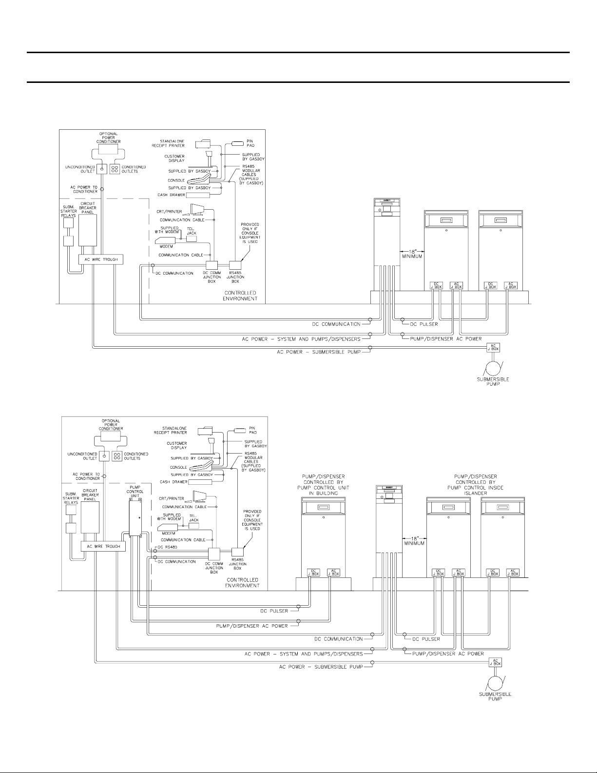
System Components Wiring - Islander
Page 6
Page 7

1. All wiring is to be installed and used in accordance with all building/fire codes, all Federal, State, and Local codes, National
Electrical Code (NFPA 70), NFPA 30, and Automotive and Marine Service Station Code (NFPA 30A) codes and regulations.
Wiring must also conform to the wiring diagram supplied with the pump/dispenser.
2. All peripheral equipment connected to the RS-232 ports must be UL-Listed, have an Electronics Industry Association (EIA)
standard RS-232 communications protocol and not be installed over a hazardous location.
3. The abo ve wirin g diagr am illustr ates a C FN System wi th ever y componen t to ind icate h ow they are in terconn ected. Componen ts
that are n ot a part of your system should be i gnor e d.
4. When using shielded cable for the RS-485 communication wiring, ground the shield to the AC ground used for the system
components (on one end only).
5. CFN island card readers (ICR's) are interchangeable with satellite Islanders in your configuration.
6. Consult the applicable section of the Installation Manual for specific system installation requirements.
7. For Isl and er II con n ectin g to Tokh eim DPT’ s, consu lt th e Pum p In terfa ce man ual or cont act G asboy T echn ical Servi ce for speci al
instructions.
Page 7
Page 8

SYSTEM AND PUMP/DISPENSER WIRING
System/Peripheral Equipment: AC Power for the system
components must come from a separate, dedicated circuit
breaker. No other equipment, including the system's pumps or
dispensers, may be powered from this breaker. Whenever
possible, one breaker should be used to supply the CFN system
components, terminal, and modem. However, it is accept able to
supply the power to different CFN system components and
accessor ies from multiple br eakers within the same panel and
the sa me phase of pow er. If necess ar y, the term inal or modem
may be on a di ffer ent separ ate, dedi cated breaker .
Power: 120 VAC + 10% 47-63 HZ.
Power conditioner: Optional.
Grounding: All system grounds must return to the same breaker
panel to ensure a common gr ound and protect the RS-485 data
loop circuitry.
Pulsers: Reed (contact closure) type pulsers require two wires
per pulser. Electronic pulsers require three wires per pulser.
See Pulser Wiring later in this documen t.
SUCTION PUMPS
The CFN pump control unit is capable of directly driving pump
motors up to 3/4 HP at 120/240 VAC or 1-1/2 HP at 240 VAC.
A start er rel ay must be used wit h pum p motor s exceed in g these
limitations. A separate circuit breaker should be supplied for
each pump to meet the current requirements and to allow for
isolated control with the circuit breaker panel in case of
problems.
DISPENSERS
9800A ELECTRONIC PUMPS
Series 9800A electronic pumps do not use the CFN pump
control unit; they are wired as independent units. See the 9800A
Installation Manual, 035296 for details.
Page 8
The CFN pump control unit can directly drive submersible
pumps up to 3/4 HP at 120/240 VAC or 1-1/2 HP at 240 VAC.
A submersible starter relay must be used with pump motors
exceeding these limitations. A separate circuit breaker is
required for each dispenser directly driving a submersible pump.
Dispensers may be grouped together on a single breaker when
the subm ersible p ump has its own br eaker. No mor e than two
dispensers should be powered from one breaker to allow
isolated control with the circuit breaker panel in case of
problems.
Page 9

WIRE SIZE
Wire Si ze
This table shows the required AC wire size for suction and
submersible pumps based on the HP rating of the pump motor
and th e distan ce from the cir cuit br eaker to th e pump/di spenser
for both 120 and 240 volt units. Use this table as a guide for
selecting the proper size wire according to the specific
inst allation requirement s for motor wi ring. All wi re should be
strand ed.
COMMUNICATION WIRING
Requirements
The CFN system utilizes RS-485, RS-422 and RS-232 modes
for communications to other CFN system components and
peripheral equipment. The Islander has four ports: two RS-485,
which are dedicated to communicating with other CFN
components; the other two are configurable for either RS-232 or
RS-422, for use with a terminal, modem, or PC. Phone line
(modem) communication may also be used when remote
commun ication to the site is desi red. In cases wh ere an I slander
internal modem is used, the remote port is not available for
external comm unication wir ing.
RS-485 Data Loop
RS-485 is used for communications between the Islander and its
peripherals. Communication takes place over RS-485 modular
cables provided with the system components and the RS-485
data loop field wiring.
Twisted pair shielded cable is highly recommended for RS-485
wiring. Although it is recommended that wires be run in a
conduit separate from AC wires, they can be combined in the
same conduit with AC wires providing UL-Listed cable with the
following specifications is used:
Conductor: 18 AWG stranded wire. 2 twisted-pairs.
Shield: Foil-wrapped 100% coverage and/or tinned copper braid
90% coverage
Drain Wire: Stranded, tinned copper, 20 AWG or larger/or
braided shield
Voltage Rating: Maximum operating voltage of 600V
Environmental: Gas- and oil-resistant; suitable for wet or dry
locations.
GASBOY can supply Belden 1063A (P/N C09655) which is a
UL-Listed, 4-conductor cable that meets the requirements listed
above. NOTE: Belden 1063A is UL-Listed but not CSA listed.
When using the above recommended cable or its equivalent,
RS-485 wires can be run with AC wires in metal conduit. The
shield drain wire must be connected to the system AC ground.
Only AC wi r es for th e syst em an d pum ps can be in st all ed in th e
AC conduit.
If using cable other than that recommended, the RS-485 field
wires must be installed in a metal conduit separate from any AC
wires.
Wiring over 100 feet must be C09655 or equivalent. Distance
from Islander to farthest CFN component is limited to 1000 feet.
Total length of all RS-485 wiring cannot exceed 1500 feet.
RS-485 modular cables required are supplied with the system.
These cables are not compatible with standard phone cables.
GASBOY su pp li ed ca bles a r e 8 feet l on g, howev er , if you n eed
to conn ect to a d evice with a modul ar conn ector, you m ust use
an RS-485 junction box to connect the device to the RS-485
wiring. The system components wiring diagrams on pages 6
and 7 sh ow proper conn ection of th e CFN components.
RS-232
RS-232 wiring is used for communication between the Islander
and EIA RS-232-compatible peripheral devices (terminal,
modem, printer, etc). Distance for RS-232 are as follows:
1-100 feet: RS-232 can be directly connected to a peripheral
device.
101-1500 feet: RS-422 and GASBOY Short Haul Modem
required.
RS-232 wiring exceeding 15 feet must be installed in metal
conduit separate from any AC wires.
Cables may be purchased from Gasboy or made by the installer.
See th e Installation Manual for cabling details.
Page 9
Page 10

PULSER WIRING REQUIREMENTS
When installed in a separate DC conduit, 18 AWG wires are
requ ired for insta llati on. Although it is r ecommen ded th at DC
pulser wires be run in a conduit separate from AC wires, they
can be combined in the same conduit with AC wires providing
UL-Listed cable with the following specifications is used:
Conductor: 18 AWG stranded wire. Number of conductors to
be determined by pulser
Shield: Foil-wrapped 100% coverage and/or tinned copper braid
90% coverage
OPTIONAL TANK MONITOR REQUIREMENTS
Islanders can be c onnected t o Veeder-Root TLS tank mon itoring
systems. All previously described RS-232 and RS-485 wiring
guidelines should be followed when wiring a tank monitoring
system. Consult the manufacturer's instructions for further
guidelines.
Drain Wire: Stranded, tinned copper, 20 AWG or larger/or
braided shield
Voltage Rating: Maximum operating voltage of 600V
Environmental: Gas- and oil-resistant; suitable for wet or dry
locations.
GASBOY can supply Belden 1063A (P/N C09655) which is a
UL-Listed, 4-conductor cable that meets the requirements listed
above. NOTE: Belden 1063A is UL-Listed but not CSA listed.
The following diagram shows the connection of the Islander to a
Veeder-Root tank monitoring system. Consult the Islander II
Installation Manual, C35963 for details on RS-232 wiring.
Page 10
Connection to a Veeder-Root TLS
Page 11

OPTIONAL MODEM REQUIREMENTS
GASBOY RS-422 Short Ha ul Modems
A GASBOY Short Haul Modem (SHM) and the appropriate
interconnect cable must be used when the RS-422
communication mode is being used to communicate to the local
or remote ports of the Islander. The SHM should be used for
distances between 100 and 1500 feet. One SHM is required at
the remote end of the communication wiring. SHM's must be
connected with private lines and will not work if connected into
a telephone network.
AC power should come from the same breaker that supplies the
peripheral devi ce or the system .
Twisted pair shielded cable is highly recommended for RS-422
wiring. Although it is recommended that wires be run in a
conduit separate from AC wires, they can be combined in the
same conduit with AC wires providing UL-Listed cable with the
following specifications is used:
Conductor: 18 AWG stranded wire. 2 twisted-pairs.
Shield: Foil-wrapped 100% coverage and/or tinned copper braid
90% coverage
Drain Wire: Stranded, tinned copper, 20 AWG or larger/or
braided shield
Voltage Rating: Maximum operating voltage of 600V
Environmental: Gas- and oil-resistant; suitable for wet or dry
locations.
GASBOY can supply Belden 1063A (P/N C09655) which is a
UL-Listed, 4-conductor cable that meets the requirements listed
above. NOTE: Belden 1063A is UL-Listed but not CSA listed.
When using the recommended C09655 or its equivalent, RS-422
wires ca n be run with AC wires in meta l conduit. The shi eld
drain wire must be con nected t o the system AC ground. Only
AC wires for th e system and pumps can be install ed in the AC
conduit.
If using cable other than that recommended, the RS-422 field
wires must be installed in a metal conduit separate from any AC
wires.
The cabl e can be r un in doors without usin g meta l condu it. The
shi eld drain wire m ust be connected to the system g round.
External Modems
The type of phone line required for communication via an
external modem is contingent upon the type of modem used and
the method of communication desired. Consult the manual that
comes with the modem for specific requirements.
Internal Modem
The Islander is available with an optional internal modem.
When this modem is installed, remote port communication is
routed through the modem in place of being wired at the
terminal block in the post. The phone line for the internal
modem must not be installed in the DC conduit. Check with
your local phone company for proper installation of the phone
line.
The 2400 baud modem is designed for 300, 1200, or 2400 baud,
full duplex, asynchronous communication. The 33600 baud
modem is designed for 1200, 2400, or 9600 baud, full duplex,
Page 11
asynchronous communications. The modem is mounted inside
the Islander at the factory. Power for the modem is supplied by
the Islander.
The mod em i s d esig n ed t o meet or exce ed t h e d ir ect con n ect i on
registration requirements of the FCC rules. This means the
modem will connect directly with a jack supplied by the phone
compan y. Th e cust omer is req uired t o ord er thi s jack and have
it in sta ll ed. To or der thi s equi pm ent from the ph on e com pan y,
specify:
1. Any one of the following jacks: RJ11C or RJ41S, OR
RJ45S.
2. The registration number of 6BHUSA-24793-DT-E.
3. The data transmission rate of 300 baud, 1200 baud, 2400
baud, or 9600 baud.
4. The Bell equivalent of 103J/212A.
Page 12

OPTIONAL FUEL PO INT
The Islander II system can be purchased or retrofitted with a
Fuel Poin t option. With Fuel Point, each vehicle is equipped
with a T-ring (tank ring). Each hose used with Fuel Point is
equipped with an N-ring (nozzle ring). When fueling the
vehicle, the antennas on the T-ring and N-ring automatically
transmit vehicle information to the Fuel Point Reader (FPR),
which in turn, transmits this information to the GASBOY
Islan der II system which authoriz es fuelin g and record s vehicl e
and transaction information.
The h ard war e r equir ed for th e F uel Poi n t opti on can be fact or yinstalled on a new system, or retrofitted to an existing system.
Refer to the following Fuel Point manuals for information on
system installation and ret ro fitting:
• Fuel Point Reader Installation, C35628
• Fuel Point Hose and Dispenser Retrofit Installation,
C35593
• Vehicle Module Installation, C35699
• Vehicle Module Programming Manual, C35629
• Fuel Point Parts, C35709
Ther e are two var iati ons on th e Fuel Poin t opti on: the s tandar d
Fuel Point option or the Fuel Point Gate option. The standard
option allows you to authorize up to 8 fueling positions. The
gate op tion allows y ou to designate a fueling position ( ho se) as a
gate controller. The gate option requires a special vehicle
module with gate antenna connectors on the vehicle and
installation of a special ground loop antenna buried in the
driveway.
GATE CONTROLLER WIRING USING GATE READER
The Islan der system ca n activa te a gate contr oller by usin g the
CFN Gate Island Reader or Gate Satellite Reader. Either of
these Gate Readers allows activation by card, Fuel Point, or
terminal command, but not via console or POS terminal.
• The CFN Gate ICR can directly switch power to a gate
controller. The maximum ratings of the switched power is
not to exceed 5A @ 30VDC or 1/8HP @ 120VAC. If the
gate controller switch control exceeds those ratings, an
auxiliary relay must be installed to handle the load. The
auxiliary relay coil is not to exceed the ratings mentioned
above.
• The Islander II system allows a loadable timeout value up
to two minutes during which time the relays are energized.
The selected time depends on the gate controller
manu facturer’s specification.
• Instead of a timed closure, the system also allows the
relays to stay energized indefinitely until a signal comes
back to turn them off. The signal is 120VAC only, and is
connected to the I/O Board’s Switch Detect connector.
Page 12 C35587 Rev. 0034
GASBOY INTERNATIONAL, INC.
A Tokheim Subsidiary
P.O. Box 309, Lansdale, PA 19446
● (215) 855-4631 ● FAX: (800) 444-5569
 Loading...