

Page 1

Commercial and Retail Series
Atlas
™
Start-up/Service Manual
MDE-4334D
Page 2

Computer Programs and Documentation
Gasboy, Greensboro, is an ISO 9001:2000 registered facility.
Underwriters Laboratories (UL):
UL File# Products listed with UL
MH4314
All dispensers and self-contained pumping
units
MH6418
Power operated Transfer Pump Models 25,
25C, 26, 27, 28, 72, 72S, 72SP , 72X, 73 and
1820
MH7404
Hand operated Transfer Pump Models 1230
Series, 1243 Series, 1520 and 1720 Series
MH10581 Key con t r o l u n i t , M o d e l G K E - B S e r i e s
Card reader terminals, Models 1000, 1000P
Site controller, Model 2000S CFN Series
Data entry terminals, Model TPK-900 Series
Fuel Point Reader System
National Conference of Weights and Measures (NCWM) - Certificate of Compliance (CoC):
Gasboy pumps and dispensers are evaluated by NCWM under the National Type Evaluation Program (NTEP). NCWM has issued the following CoC:
CoC# Product Model # CoC# Product Model # CoC# Product Model #
95-179 Dispenser
9100 Retail Series, 8700
Series, 9700 Series
91-019 Dispenser
9100 Commercial
Series
05-002 Atlas
8700K, 8800K,
9100K, 9200K, 9800K
95-136 Dispenser 9800 Series 91-057 Controller
1000 Series FMS,
2000S-CFN Series
New York City Fire Department (NYFD):
NYFD C of A # Product
4823 9100A, 9140A, 9152A, 9153A,
9800A, 9840A, 9850A, 9852A,
9853A, 9140
4997 9822A, 9823A
5046 9100Q, 9140Q, 9152Q, 9153Q,
9800Q, 9840Q, 9852Q, 9853Q
5087 8753K, 8853K, 9153K, 9853K
(restricted to diesel and non-
retail gasoline sales)
5091 8752K, 9152K
5129 9122K, 9123K, 9822K, 9823K
California Air Resources Board (CARB):
Executive Order # Product
G-70-52-AM Balance Vapor Recovery
G-70-150-AE VaporVac
Registered trademarks
ASTRA
®
Fuel Point
®
Gasboy
®
Keytrol
®
Slimline
®
Additional US and foreign trademarks pending.
Other brand or product names shown may be
trademarks or registered trademarks of their
respective holders.
Non-registered trademarks
Atlas™
Consola™
Infinity™
Federal Communications Commission (FCC) Warning
All Gasboy computer programs (including software on diskettes and within memory chips) and documentation are copyrighted by, and shall remain the property of, Gasboy. Such
computer programs and documents may also contain trade secret information. The duplication, disclosure, modification, or unauthorized use of computer programs or
documentation is strictly prohibited, unless otherwise licensed by Gasboy.
This equipment has been tested and found to comply with the limits for a Class A digital device pursuant to Part 15 of the FCC Rules. These limits are designed to provide
reasonable protection against harmful interference when the equipment is operated in a commercial environment. This equipment generates, uses, and can radiate radio frequency
energy, and if not installed and used in accordance with the instruction manual, may cause harmful interference to radio communications. Operation of this equipment in a
residential area is likely to cause harmful interference in which case the user will be required to correct the interference at his own expense. Changes or modifications not expressly
approved by the manufacturer could void the user’s authority to operate this equipment.
Approvals
Trademarks
This document is subject to change without notice.
E-mail: literature@gasboy.com · Internet: http://www.gasboy.com
2013 GASBOY · All Rights Reserved
Page 3

Table of Contents
Table of Contents
1 – Read This First 1-1
Introduction . . . . . . . . . . . . . . . . . . . . . . . . . . . . . . . . . . . . . . . . . . . . . . . . . . . . . . . . . . . . . . . . . . . . . 1-1
Purpose . . . . . . . . . . . . . . . . . . . . . . . . . . . . . . . . . . . . . . . . . . . . . . . . . 1-1
Important Information About Releases. . . . . . . . . . . . . . . . . . . . . . . . . . 1-1
Topics in This Section . . . . . . . . . . . . . . . . . . . . . . . . . . . . . . . . . . . . . . 1-1
Who Must Use This Manual. . . . . . . . . . . . . . . . . . . . . . . . . . . . . . . . . . 1-2
Service Protocol. . . . . . . . . . . . . . . . . . . . . . . . . . . . . . . . . . . . . . . . . . . 1-2
Related Documents . . . . . . . . . . . . . . . . . . . . . . . . . . . . . . . . . . . . . . . . 1-3
Abbreviations and Acronyms . . . . . . . . . . . . . . . . . . . . . . . . . . . . . . . . . 1-4
Common Terms Used . . . . . . . . . . . . . . . . . . . . . . . . . . . . . . . . . . . . . . 1-5
DEF Special Considerations . . . . . . . . . . . . . . . . . . . . . . . . . . . . . . . . . . . . . . . . . . . . . . . . . . .
Troubleshooting DEF Freeze. . . . . . . . . . . . . . . . . . . . . . . . . . . . . . . . . 1-7
If DEF Freezes. . . . . . . . . . . . . . . . . . . . . . . . . . . . . . . . . . . . . . . . . . . . 1-8
Important Requirements for
Model Information . . . . . . . . . . . . . . . . . . . . . . . . . . . . . . . . . . . . . . . . . . . . . . . . . . . . . . . .
E85 Units . . . . . . . . . . . . . . . . . . . . . . . . . . . . . . . . . . . . . . . . . . . . . . . . 1-9
Mechanical Retail Pump/Dispenser . . . . . . . . . . . . . . . . . . . . . . . . . . . 1-10
Electronic Retail Pump/Dispenser . . . . . . . .
Serial Number Plate and Date Codes . . . . .
Atlas Model Number Table. . . . . . . . . . . . . . . . . . . . . . . . . . . . . . . . . . 1-13
Options Overview. . . . . . . . . . . . . . . . . . . . . . . . . . . . . . . . . . . . . . . . . 1-15
. . . . . . . . . . . . . . . . . . . . 1-11
. . . . . . . . . . . . . . . . . . . . 1-12
. . . . . 1-6
. . . . . . . 1-10
2 – Important Safety Information 2-1
3 – Start-up Procedures 3-1
Introduction . . . . . . . . . . . . . . . . . . . . . . . . . . . . . . . . . . . . . . . . . . . . . . . . . . . . . . . . . . . . . . . . . . . . . 3-1
Purpose . . . . . . . . . . . . . . . . . . . . . . . . . . . . . . . . . . . . . . . . . . . . . . . . . 3-1
Important Information About Releases. . . . . . . . . . . . . . . . . . . . . . . . . . 3-1
Topics in This Section . . . . . . . . . . . . . . . . . . . . . . . . . . . . . . . . . . . . . . 3-1
How to Use This Section . . . . . . . . . . . . . . . . . . . . . . . . . . . . . . . . . . . . 3-1
Certificate of Conformance (CoC) Numbers . . . . . . . . . . . . . . . . . . . . . . . . . . . . . . . . . . . . . . . . . . . . 3-1
Start-up Checklists . . . . . . . . . . . . . . . . . . . . . . . . . . . . . . . . . . . . . . . . . . . . . . . . . . . . . . .
Installation Checklists. . . . . . . . . . . . . . . . . . . . . . . . . . . . . . . . . . . . . . . 3-2
Meter Calibration. . . . . . . . . . . . . . . . . . . . . . . . . . . . . . . . . . . . . . . . . . . . . . . . . . . . . . . . .
Gasboy Atlas (Gallon Unit of Measure) . . . . . . . . . . . . . . . . . . . . . . . . . 3-4
. . . . . . . . 3-2
. . . . . . . . 3-4
4 – Pump Programming 4-1
Introduction . . . . . . . . . . . . . . . . . . . . . . . . . . . . . . . . . . . . . . . . . . . . . . . . . . . . . . . . . . . . . . . . . . . . . 4-1
Purpose . . . . . . . . . . . . . . . . . . . . . . . . . . . . . . . . . . . . . . . . . . . . . . . . . 4-1
Important Information About Releases. . . . . . . . . . . . . . . . . . . . . . . . . . 4-1
Programming Overview. . . . . . . . . . . . . . . . . . . . . . . . . . . . . . . . . . . . . . . . . . . . . . . . . . . . . . .
9800 Series Electronic Commercial Units . . . . . . . . . . . . . . . . . . . . . . . 4-1
8800 Series Electronic Retail Units . . . . . .
Mechanical Commercial Units . . . . . . . . . . . . . . . . . . . . . . . . . . . . . . . . 4-3
Configuring 9800 Series . . . . . . . . . . . . . . . . . . . . . . . . . . . . . . . . . . . . . . . . . . . . . . . . . . . . .
General Configuration Details . . . . . . . . . . . . . . . . . . . . . . . . . . . . . . . . 4-3
Configuration Steps . . . . . . . . . . . . . . . . . . . . . . . . . . . . . . . . . . . . . . . . 4-5
ATC Setup . . . . . . . . . . . . . . . . . . . . . . . . . . . . . . . . . . . . . . . . . . . . . . 4-10
Error Codes . . . . . . . . . . . . . . . . . . . . . . . . . . . . . . . . . . . . . . . . . . . . . 4-11
. . . . . . . . . . . . . . . . . . . . . . 4-2
. . . . . 4-1
. . . . . . 4-3
MDE-4334D Atlas™ Start-up and Service Manual · July 2013 Page i
Page 4

Table of Contents
Programming 8800 Series Units. . . . . . . . . . . . . . . . . . . . . . . . . . . . . . . . . . . . . . . . . . . . . . . . . . . . .4-11
General Programming Details. . . . . . . . . . . . . . . . . . . . . . . . . . . . . . . .4-12
Display Conventions . . . . . . . . . . . . . . . . . . . . . . . . . . . . . . . . . . . . . . .4-14
Programming Steps for 8800 Series Units . . . . . . . . . . . . . . . . . . . . . .4-15
Level 1 Programming . . . . . . . . . . . . . . . . . . . . . . . . . . . . . . . . . . . . . .4-15
Level 2 Programming . . . . . . . . . . . . . . . . . . . . . . . . . . . . . . . . . . . . . .4-18
Level 3 Programming . . . . . . . . . . . . . . . . . . . . . . . . . . . . . . . . . . . . . .4-22
Option and Miscellaneous Programming/Data Acquisition. . . . . . . . . .4-24
Displaying Pump Totals . . . . . . . . . . . . . . . . . . . . . . . . . . . . . . . . . . . .4-25
Error Codes and Descriptions. . . . . . . . . . . . . . . . . . . . . . . . . . . . . . . .4-26
Programming 8700 Series Units. . . . . . . . . . . . . . . . . . . . . . . . . . . . . . . . . . . . . . . . . . . . . . . . . . .
General Programming Details. . . . . . . . . . . . . . . . . . . . . . . . . . . . . . . .4-27
Programming Steps . . . . . . . . . . . . . . . . . . . . . . . . . . . . . . . . . . . . . . .4-27
. .4 -27
5 – Electronic and Electrical Components 5-1
Introduction. . . . . . . . . . . . . . . . . . . . . . . . . . . . . . . . . . . . . . . . . . . . . . . . . . . . . . . . . . . . . . . . . . . . . .5-1
Purpose. . . . . . . . . . . . . . . . . . . . . . . . . . . . . . . . . . . . . . . . . . . . . . . . . .5-1
Important Information About Releases . . . . .
Topics in This Section. . . . . . . . . . . . . . . . . . . . . . . . . . . . . . . . . . . . . . .5-1
How to Use This Section. . . . . . . . . . . . . . . . . . . . . . . . . . . . . . . . . . . . .5-1
Electronics Highlights. . . . . . . . . . . . . . . . . . . . . . .
Retail Parts by Name . . . . . . . . . . . . . . . . . . . . . . . . . . . . . . . . . . . . . . .5-2
Retail Parts by Number. . . . . . . . . . . . . . . . . . . . . . . . . . . . . . . . . . . . . .5-3
Commercial Parts by Number. . . . . . . . . . . . . . . . . . . . . . . . . . . . . . . . .5-4
8800 Series Electronic Retail Units. . . . . . . . . . . . . . . . . . . . . . . . . . . . .5-7
System and Component Overview . . . . . . . . . . . . . . . . . . . . . . . . . . . . .5-8
About Service Procedures . . . .
Working on Electronic and Electrical Components. . . . . . . . .
Component Overview. . . . . . . . . . . . . . . . . . . . . . . . . . . . . . . . . . . . . . . . . . . . . . . . . . . . . . .
PCAs . . . . . . . . . . . . . . . . . . . . . . . . . . . . . . . . . . . . . . . . . . . . . . . . . . . . . . . . . . . . . .
Atlas 9800 Parts. . . . . . . . . . . . . . . . . . . . . . . . . . . . . . . . . . . . . . . . . . . . . . . . . . . . . . . . . .
Accessing Electronic Components. . . . . . . . . . . . . . . . . . . . . . . . . . . . . . . . . . . . . . . . . . . . . . . . . .
Installing Atlas 9800 Power Supply
Installing Atlas 9800 CPU Board (M06333KXXXX) . . . . . . . . . . .
Installing Atlas 9800 Pulse-out I/F with EM Totaliz
Atlas 8800 Parts. . . . . . . . . . . . . . . . . . . . . . . . . . . . . . . . . . . . . . . . . . . . . . . . . . . . . . . . . .
. . . . . . . . . . . . . . . . . . . . . . . . . . . . . . . . . . . . . . . . . . . . . . . . . . . . . .5-8
Preparing for Service . . . . . . . . . . . . . . . . . . . . . . . . . . . . . . . . . . . . . . .5-9
Preventing ESD. . . . . . . . . . . . . . . . . . . . . . . . . . . . . . . . . . . . . . . . . . . .5-9
Hazardous Materials . . . .
Atlas 9800 PCAs. . . . . . . . . . . . . . . . . . . . . . . . . . . . . . . . . . . . . . . . . .5-12
Atlas 9800 CPU Board (M06333KXXXX) . . . . . . . . . . . . . . . . . . . . . . .5-25
Atlas 9800 Power Supply (M07588A00X). . . . . . . . . . . . . . . . . . . . . . .5-28
Atlas 9800 Serial EEPROM Board (M06656K00X). . . . . . . . . . . . . . . .5-29
Atlas 9800 Pulse-out I/F Board with
EM Totalizer Drive (M06587A001) . . . . . . . . . . . . . . . . . . . . . . . . . . . .5-30
K-pump RS-485 with Totalizer (M06725A001) . . . . . . . . . . . . . . . . . . .5-31
(M07588A00X). . . . . . . . . . . . . . . . . . . . . . . . . . . . . . . . . . . . . .5-32
Jumpers JP1, JP2, and JP3 . . . . . . . . . . . . . . . . . . . . . . . . . . . . . . . . .5-34
Jumpers JP4 and JP5. . . . . . . . . . . . . . . . . . . . . . . . . . . . . . . . . . . . . .5-35
Configurations. . . . . . . . . . . . . . . . . . . . . . . . . . . . . . . . . . . . . . . . . . . .5-35
Pump Interface PCA [T18994 (Atlas 8800 Only)] . . . . . . . . . . . . . . . . .5-37
Pump Controller PCA [T20092 (Atlas 8800 Only)] . . . . . . . . . . . . . . . .5-38
ATC Component Overview (Atlas 8800 Only). . . . . . . . . . . . . . . . . . . .5-40
Manager Keypad [T17549-G1 (Atlas 8800 Only)]
Display Backlight PCA (0.6-inch) [T17622-G9 (Atlas 8800 Only)] . . . .5-43
. . . . . . . . . . . . . . . . . . . . . . . . . . . . . . . . . . . . . . .5-1
. . . . . . . . . . . . . . . . . . . . . . . . . . . . . . .5-9
. . . . . . . . . . . . . . . . . . . . . . . . . . . . . . . . . . .5-10
. . . . . . . . . . . . . . . . . . . . . . . . . . .5-33
er Drive Board (M06587A001). . . . . . . . . . . . . . .5-34
. . . . . . . . . . . . . . . . . . . . .5-1
. . . . . .5-11
. . . . . . . . . . .5-12
. . . . . . .5-25
.5-31
. . . . . . .5-37
. . . . . . . . . . . . . . . . .5-42
Page ii MDE-4334D Atlas™ Start-up and Service Manual · July 2013
Page 5

Table of Contents
LCD Display (0.6-inch) [T17701-G1 (Atlas 8800 Only)]. . . . . . . . . . . . 5-44
LCD Display (0.6-inch) [T18981-G1 (Atlas 8800 Only)]. . . . . . . . . . . . 5-45
Power Supplies . . . . . . . . . . . . . . . . . . . . . . . . . . . . . . . . . . . . . . . . . . . . . . . . . . . . . . . . . .
Replacing Fuses . . . . . . . . . . . . . . . . . . . . . . . . . . . . . . . . . . . . . . . . . 5-46
Main Power Supply (T19868-G1). . . . . . . . . . . . . . . . . . . . . . . . . . . . . 5-48
I.S Barrier Assembly ATC (T19428-G1). . . . . .
Q10131-03 Fuse . . . . . . . . . . . . . . . . . . . . . . . . . . . . . . . . . . . . . . . . . 5-50
Electro-mechanical Registers and Totalizers . . . . . . . . . . .
About Displays . . . . . . . . . . . . . . . . . . . . . . . . . . . . . . . . . . . . . . . . . . . 5-50
Pulsers. . . . . . . . . . . . . . . . . . . . . . . . . . . . . . . . . . . . . . . . . . . . . . . . . . . . . . . . . . . . . .
About Standard Pulsers . . . . . . . . . . . . . . .
Testing Pulsers and I.S Barriers . . . . . . . . . . . . . . . . . . . . . . . . . . . . . 5-53
Pulser Drive Assembly. . . . . . . . . . . . . . . . . . . . . . . . . . . . . . . . . . . . . 5-54
About Ultra-Hi Pulsers . . . . . . . . . . . . . . . .
Heater . . . . . . . . . . . . . . . . . . . . . . . . . . . . . . . . . . . . . . . . . . . . . . . . . . . . . . . . . . . . . .
DEF Heating System (Commercial Cold W
Coriolis Meter Interface Board (M10030A001).
. . . . . . . . . . . . . . . . . . . . . . . . . . . . . . . 5-50
. . . . . . . . . . . . . . . . . . 5-50
. . . . . . . . . . . . . . . . . . . . . 5-53
. . . . . . . . . . . . . . . . . . . . . 5-55
eather DEF Units Only) . . 5-55
. . . . . . . . . . . . . . . . . . 5-57
. . . . . . . 5-46
. . . . . . . . . . 5-53
. . . . . . . . . . 5-55
6 – Hydraulic/Mechanical Components 6-1
Introduction . . . . . . . . . . . . . . . . . . . . . . . . . . . . . . . . . . . . . . . . . . . . . . . . . . . . . . . . . . . . . . . . . . . . . 6-1
Purpose . . . . . . . . . . . . . . . . . . . . . . . . . . . . . . . . . . . . . . . . . . . . . . . . . 6-1
Important Information About Releases. . . . . . . . . . . . . . . . . . . . . . . . . . 6-1
Topics in This Section . . . . . . . . . . . . . . . . . . . . . . . . . . . . . . . . . . . . . . 6-1
How to Use This Section . . . . . . . . . . . . . . . . . . . . . . . . . . . . . . . . . . . . 6-1
Hydraulic and Mechanical Highlights. . . . . . . . . . . . . . .
2-stage Solenoid Valve . . . . . . . . . . . . . . . . . . . . . . . . . . . . . . . . . . . . . 6-2
Meter . . . . . . . . . . . . . . . . . . . . . . . . . . . . . . . . . . . . . . . . . . . . . . . . . . . 6-3
General Service Procedures . . . . . . . . . . . . . . . . . . . . . . . . . . . . . . . . . . . . . . . . . . . . . . . . . . .
Working on Hydraulic Components . . . . . . . . . . . . . . . . . . . . . . . . . . . . 6-5
Servicing Hydraulic Components. . . . . . . . . . . . . . . . . . . . . . . . . . . . . . 6-6
Servicing Seals, O-rings, and Gaskets . . . . . . . . . . . . . . . . . . . . . . . . . 6-7
Pipes and Hydraulic Plumbing . . . . . . . . . . . . . . . . . . . . . . . . . . . . . . . . 6-7
Torque Specifications. . . . . . . . . . . . . . . . . . . . . . . . . . . . . . . . . . . . . . . 6-8
Purging Air from System . . . . . . . . . . . . . . . . . . . . . . . . . . . . . . . . . . . . . . . . . . . . . . . . . . . . .
About Purging System . . . . . . . . . . . . . . . . . . . . . . . . . . . . . . . . . . . . . . 6-9
Purging Product Lines (New Installations). . . .
Purging Pumps and Dispensers (with Fuel in Product Lines) . . . . . . . 6-11
Purging Air in DEF Systems. . . . . . . . . . . .
Measuring Flow Rate. . . . . . . . . . . . . . . . . . . . . . . . . . . . . . . . . . . . . . . . . . . . . . . . . . . . . . . .
Measuring Pressure and Vacuum . . . . . . . . . . . . . . . . . . . . . . . . . . . . . . . . . . . . . . . . . . . . . . . . . . .
Using Pressure Gauge. . . . . . . . . . . . . . . . . . . . . . . . . . . . . . . . . . . . . 6-14
Pressure Measuring Locations on Unit . . . . . . . . . . . . . . . . . . . . . . . . 6-15
Measuring Pressure Drop for Pumps and Dispensers
Analyzing Pressure Drop for Pumps
Measuring Vacuum for Pump. . . . . . . . . . . .
About Vacuum Readings . . . . . . . . . . . . . .
Measuring Dry Vacuum for Pump . . . . . . . .
Measuring Wet Vacuum and Pressure for Pump
Meter Calibration. . . . . . . . . . . . . . . . . . . . . . . . . . . . . . . . . . . . . . . . . . . . . . . . . . . . . . . . .
About Calibrating Meters . . . . . . . . . . . . . .
CFT Meter Calibration Adjustment for
Super-Hi™ Models (All Models Excluding 9850K and 9850KX) . . . . . 6-23
LC Meter Calibration Adjustment for Ultra-Hi
Models 9850K and 9850KX . . . . . . . . . . . . . . . . . . . . . . . . . . . . . . . . . 6-25
Calibration Adjustment
. . . . . . . . . . . . . . . . . . . . . . . . . . . . . . . . . . . 6-2
. . . . . 6-4
. . . . . . 6-9
. . . . . . . . . . . . . . . . . . 6-10
. . . . . . . . . . . . . . . . . . . . . 6-12
. . . . . 6-13
6-14
. . . . . . . . . . . . . 6-16
and Dispensers . . . . . . . . . . . . . 6-17
. . . . . . . . . . . . . . . . . . . . 6-19
. . . . . . . . . . . . . . . . . . . . . 6-19
. . . . . . . . . . . . . . . . . . . . 6-19
. . . . . . . . . . . . . . . . . 6-20
. . . . . . . 6-22
. . . . . . . . . . . . . . . . . . . . . 6-22
Standard, Hi-Flow, and
for E85/DEF Units
MDE-4334D Atlas™ Start-up and Service Manual · July 2013 Page iii
Page 6

Table of Contents
[Electronic Calibration (ECAL)] . . . . . . . . . . . . . . . . . . . . . . . . . . . . . . .6-26
Meters. . . . . . . . . . . . . . . . . . . . . . . . . . . . . . . . . . . . . . . . . . . . . . . . . . . . . . . . . . . . . .
. . . . . . . . . . .6-26
About Meters. . . . . . . . . . . . . . . . . . . . . . . . . . . . . . . . . . . . . . . . . . . . .6-26
CFT/E85 Meters . . . . . . . . . . . . . . . . . . . . . . . . . . . . . . . . . . . . . . . . . .6-27
Repairing CFT/E85 Meters . . . . . . . . . . . . . . . . . . . . . . . . . . . . . . . . . .6-28
Replacing Cylinder Cover and Gasket (Cy
Replacing O-rings (Body and Cover Leaks) . . . .
linder Cover Leaks) . . . . . .6-29
. . . . . . . . . . . . . . . . .6-30
Calibrating Wheel Parts Repair. . . . . . . . . . . . . . . . . . . . . . . . . . . . . . .6-31
Replacing Piston Cups . . . . . . . . . . . . . . . . . . . . . . . . . . . . . . . . . . . . .6-31
Removing/Replacing Shaft Seal and Gasket (Upper Seal Leaks) . . . .6-33
LC Meters . . . . . . . . . . . . . . . . . . . . . . . . . . . . . . . . . . . . . . . . . . . . . . .6-34
Removing/Replacing LC Meters . . . . . . . . . . . . . . . . . . . . . . . . . . . . . .6-35
Coriolis Meter . . . . . . . . . . . . . . . . . . . . . . . . . . . . . . . . . . . . . . . . . . . .6-35
Filters and Strainers . . . . . . . . . . . . . . . . . . . . . . . . . . . . . . . . . . . . . . . . . . . . . . . . . . . . . .
. . . . . . .6-37
About Filters . . . . . . . . . . . . . . . . . . . . . . . . . . . . . . . . . . . . . . . . . . . . .6-37
Servicing Filters. . . . . . . . . . . . . . . . . . . . . . . . . . . . . . . . . . . . . . . . . . .6-38
About Strainers . . . . . . . . . . .
. . . . . . . . . . . . . . . . . . . . . . . . . . . . . . . .6-40
DEF Strainer . . . . . . . . . . . . . . . . . . . . . . . . . . . . . . . . . . . . . . . . . . . . .6-40
Servicing Strainers . . . . . . . . . . . . . . . . . . . . . . . . . . . . . . . . . . . . . . . .6-40
Hanging Hardware . . . . . . . . . . . . . . . . . . . . . . . . . . . . . . . . . . . . . . . . . . . . . . . . . . . . . . . .
About Hanging Hardware . . . . . . .
. . . . . . . . . . . . . . . . . . . . . . . . . . . .6-41
. . . . . . .6-41
Hoses and Flow Restrictors . . . . . . . . . . . . . . . . . . . . . . . . . . . . . . . . .6-41
Breakaway Valves. . . . . . . . . . . . . . . . . . . . . . . . . . . . . . . . . . . . . . . . .6-44
Testing Hose and Hanging Hardware Continuity . . . . . . . . . . . . . . . . .6-46
Internal Hose Retrievers
Pumping Unit . . . . . . . . . . . . . . . . . . . . . . . . . . . . . . . . . . . . . . . . . . . . . . . . . . . . . . . . . .
and Clamps. . . . . . . . . . . . . . . . . . . . . . . . . .6-48
. . . . . . . . .6-50
GPU Pumping Unit . . . . . . . . . . . . . . . . . . . . . . . . . . . . . . . . . . . . . . . .6-50
Servicing Strainer Check Valve. . . . . . . . . . . . . . . . . . . . . . . . . . . . . . .6-52
Servicing Pressure Control Valve (PCV)
Servicing Bypass/Pressure Relief
Servicing Rotor and Shaft Assembly
. . . . . . . . . . . . . . . . . . . . . . . .6-54
Valve (PRV) . . . . . . . . . . . . . . . . . .6-55
. . . . . . . . . . . . . . . . . . . . . . . . . . .6-57
XU2A Pumping Unit for 9850K . . . . . . . . . . . . . . . . . . . . . . . . . . . . . . .6-58
Sump for 9850K . . . . . . . . . . . . . . . . . . . . . . . . . . . . . . . . . . . . . . . . . .6-61
Pump Motor . . . . . . . . . . . . . . . . . . . . . . . . . . . . . . . . . . . . . . . . . . . . . . . . . . . . . . . . . . .
About Electric Motor for Self-contained Pump Units
. . . . . . . . . . . . . . .6-62
. . . . . . . . .6-62
Belts and Pulleys. . . . . . . . . . . . . . . . . . . . . . . . . . . . . . . . . . . . . . . . . .6-63
Belt Adjustment. . . . . . . . . . . . . . . . . . . . . . . . . . . . . . . . . . . . . . . . . . .6-64
Valves. . . . . . . . . . . . . . . . . . . . . . . . . . . . . . . . . . . . . . . . . . . . . . . . . . . . . . . . . . . . . .
. . . . . . . . . . .6-65
Solenoid Valves . . . . . . . . . . . . . . . . . . . . . . . . . . . . . . . . . . . . . . . . . .6-65
Solenoid Valve and Filter Manifold . . . . . . . .
. . . . . . . . . . . . . . . . . . . .6-67
Solenoid Valves for 9 X 40, 9850 and 9 X 53 with
Satellite Outlet Piping . . . . . . . . . . . . . . . . . . . . . . . . . . . . . . . . . . . . . .6-68
Meter Check Valve . . . . . . . . . . . . . . . . . . . . . . . . . . . . . . . . . . . . . . . .6-69
Shear Valves. . . . . . . . . . . . . . . . . . . . . . . . . . . . . . . . . . . . . . . . . . . . .6-70
T-52A Pressure Regulator Valve Option. . . . . . . . . . . . . . . . . . . . . . . .6-72
Vapor Recovery Stage 2 Balance Type . . . . . . . . . . . . . . . . . . . . . . . . . . . . . . . . . . . . . . . . . . . . . . .6
Troubleshooting . . . . . . . . . . . . . . . . . . . . . . . . . . . . . . . . . . . . . . . . . .6-73
Mechanical Computers. . . . . . . . . . . . . . . . . . . . . . . . . . . . . . . . . . . . . . . . . . . . . . . . . . . . . .
DEF Nozzle . . . . . . . . . . . . . . . . . . . . . . . . . . . . . . . . . . . . . . . . . . . . . . . . . . . . . . . . . . .
. . . . . .6-73
. . . . . . . . .6-74
Nozzle Door Mechanism (Cold Weather Units Only) . . . . . . . . . . . . . .6-74
-72
Page iv MDE-4334D Atlas™ Start-up and Service Manual · July 2013
Page 7

Table of Contents
7 – Troubleshooting Tables 7-1
Introduction . . . . . . . . . . . . . . . . . . . . . . . . . . . . . . . . . . . . . . . . . . . . . . . . . . . . . . . . . . . . . . . . . . . . . 7-1
Purpose . . . . . . . . . . . . . . . . . . . . . . . . . . . . . . . . . . . . . . . . . . . . . . . . . 7-1
Important Information About Releases. . . . . . . . . . . . . . . . . . . . . . . . . . 7-1
Topics in This Section . . . . . . . . . . . . . . . . . . . . . . . . . . . . . . . . . . . . . . 7-1
How to Use This Section . . . . . . . . . . . . . . . . . . . . . . . . . . . . . . . . . . . . 7-1
Troubleshooting Tables (Commercial Electronic and Retail Elec
Sample Troubleshooting Form. . . . . . . . . . .
Priority Codes. . . . . . . . . . . . . . . . . . . . . . . . . . . . . . . . . . . . . . . . . . . . . 7-4
Table 1: Communications to Console . . . . . . . . . . . . . . . . . . . . . . . . . . 7-4
Table 2: Fuel Delivery (All Units) . . . . . . . . . . . . . . . . . . . . . . . . . . . . . . 7-5
Table 3: Electronic Displays, Electric Reset,
Table 4: Error Codes 10-44 . . . . . . . . . . . . . . . . . . . . . . . . . . . . . . . . . . 7-7
Table 5: Handle Responses, Leaks, Noise, and
Table 6: Repeated Problems and STPs. . . . . . . . . . . . . . . . . . . . . . . . 7-10
tronic Units) . . . . . . . . . . . . . . . . . . 7-2
. . . . . . . . . . . . . . . . . . . . . 7-3
and Calibration . . . . . . . . 7-6
Presets (All Units) . . . 7-9
8 – Wiring and Configuration 8-1
Introduction . . . . . . . . . . . . . . . . . . . . . . . . . . . . . . . . . . . . . . . . . . . . . . . . . . . . . . . . . . . . . . . . . . . . . 8-1
Purpose . . . . . . . . . . . . . . . . . . . . . . . . . . . . . . . . . . . . . . . . . . . . . . . . . 8-1
Important Information About Releases. . . . . . . . . . . . . . . . . . . . . . . . . . 8-1
Topics in This Section . . . . . . . . . . . . . . . . . . . . . . . . . . . . . . . . . . . . . . 8-1
Cable Block Diagrams. . . . . . . . . . . . . . . . . . . . . . . . . . . . . . . . . . . . . . . . . . . . . . . . . . . . . . .
Block Diagram Atlas Commercial (Including DEF and
E85 Models) M05193. . . . . . . . . . . . . . . . . . . . . . . . . . . . . . . . . . . . . . . 8-1
Atlas Hydraulics, Bezel, and Door Configurat
ions. . . . . . . . . . . . . . . . . . . . . . . . . . . . . . . . . . . . . . . . 8-2
. . . . . . 8-1
9 – Preventive Maintenance and Inspection 9-1
Introduction . . . . . . . . . . . . . . . . . . . . . . . . . . . . . . . . . . . . . . . . . . . . . . . . . . . . . . . . . . . . . . . . . . . . . 9-1
Purpose . . . . . . . . . . . . . . . . . . . . . . . . . . . . . . . . . . . . . . . . . . . . . . . . . 9-1
Important Information About Releases. . . . . . . . . . . . . . . . . . . . . . . . . . 9-1
Topics in This Section . . . . . . . . . . . . . . . . . . . . . . . . . . . . . . . . . . . . . . 9-1
How to Use This Section . . . . . . . . . . . . . . . . . . . . . . . . . . . . . . . . . . . . 9-1
Preventive Maintenance . . . . . . . . . . . . . . . . . . . . . . . . . . . . . . . . . . . . . . . . . . . . . . . . . . . . .
Maintenance Procedures and Parts. . . . . . . . . . . . . . . . . . . . . . . . . . . . 9-1
Maintenance of Vendor Supplied Parts . . . . . . . . . . . . . . . . . . . . . . . . . 9-2
Performing Inspections . . . . . . . . . . . . . . . . . . . . . . . . . . . . . . . . . . . . . . . . . . . . . . . . . . . . . .
Safety Warnings. . . . . . . . . . . . . . . . . . . . . . . . . . . . . . . . . . . . . . . . . . . 9-2
Replacements and Adjustments . . . . . . . . . . . . . . . . . . . . . . . . . . . . . . . . . . . . . . . . . . . . . . . . . .
Filter Strainer Replacement . . .
Adjusting Belts (Suction Pumps Only) . . . . . . . . . . . . . . . . . . . . . . . . . . 9-4
Preserving Finish. . . . . . . . . . . . . . . . . . . . . . . . . . . . . . . . . . . . . . . . . . . . . . . . . . . . . . . . .
Preserving Finish of Fueling Equipment . . . . . . . . . . . . . . . . . . . . . . . . 9-5
Preventive Maintenance Table . . . . . . . . . . . . . . . . . . . . . . . . . . . . . . . . . . . . . . . . . . . . . . . . . . .
. . . . . . . . . . . . . . . . . . . . . . . . . . . . . . . 9-4
. . . . . . 9-1
. . . . . . 9-2
. . . 9-4
. . . . . . . . 9-5
. . . 9-6
Index Index-1
MDE-4334D Atlas™ Start-up and Service Manual · July 2013 Page v
Page 8

Table of Contents
This page is intentionally left blank.
Page vi MDE-4334D Atlas™ Start-up and Service Manual · July 2013
Page 9

Introduction Read This First
1 – Read This First
Introduction
Purpose
This section contains a general introduction, service protocol, safety, and model number
information.
Sections of this manual provide start-up and service information for
dispensers. This manual is a general service guide and not a replacement for Gasboy
certified training. Certified training includes instructions on safety procedures, use of test
equipment and common tools, wiring requirements, and electrical service procedures. The
sections in this manual cover the following topics:
Topics Page
Read This F
Important Safety Information 2-1
Start-up Procedures 3-1
Pump Programming 4-1
Electronic and Electrical Components 5-1
Hydraulic/Mechanical Components 6-1
Troubleshooting Tables 7-1
Wiring and Configuration 8-1
Preventive Maintenance and Inspection 9-1
irst 1-1
Important Information About Releases
Sections of this manual may be released or updated independently to supply the most current
data. Information about release date and version for independently released sections will be
included in the section title and footer of the document. For the latest updates, refer to
Gilbarco Online Documentation (GOLD
Atlas™ pumps and
®
Atlas
®
).
This section was last updated
in July 2013.
Topics in This Section
Topic Page
DEF Special Considerations 1-6
MDE-4334D Atlas™ Start-up and Service Manual · July 2013 Page 1-1
Page 10

Read This First Introduction
Who Must Use This Manual
This manual is intended for Gasboy Atlas Authorized Service Contractors (ASCs) who have
been trained and certified by attending Gasboy certified training classes. These ASCs must be
aware of the safety requirements and basic troubleshooting techniques, such as reading a
volt/ohmmeter, reading pressure, and so on, and understanding the differences
between
various Gasboy Atlas products, options, and functionalities.
If you have not attended the Gasboy training, contact the Gasboy Training Department. For
contact information, refer to “
Gasboy Contact Information”.
Service Protocol
A Service Technician requesting technical assistance must do the following:
1 Be available at the site.
2 When placing the call, ensure that the following are available:
• Unit model and serial number
• Site name and telephone number
• Your technician number
• Problem description and history
• All required recommended spare parts
• Manuals available for reference
3 Call the Technical Support Department at 1-800-444-5529. Refer to the Customer Service
Report (CSR) number, if previously assigned.
Using Replacement Parts
Use only genuine Gasboy Atlas replacement parts. Use of other parts will void warranty and
could affect unit conformance to various national, local or state codes.
Gasboy
Information Required Contact Details
Schedule training Gasboy Training Department
Technical assistance, customer service, and
warr
Explanation of Gasboy’s warranty policy For assistance, contact your local Ga
T
echnical literature, parts manuals, and other
documents
Contact Information
anty service
TechnicalTraining@gilbarco.com
Gasboy Technical Support at 1-800-444-5529
Helpdesk@gasboy.com
sboy Distributor
y Literature Department at (336) 547-5661
Gasbo
Page 1-2 MDE-4334D Atlas™ Start-up and Service Manual · July 2013
Page 11

Introduction Read This First
Related Documents
Following documents may be helpful when servicing the Gasboy Atlas equipment:
For a complete list of documents available,
refer to P-7001 Gasboy GOLD and Literature
Guide. For information regarding Gasboy Atlas documentation, contact the Literature
Department at 336-547-5661.
Document
Number Description GOLD Library
®
C35963 CFN
FE-356 Atlas Pump and Dispenser Field Wiring Gasboy Parts List & Wiring Diagrams
FE-357 Atlas Pump Retail/Commercial Field Wiring Gasboy Parts List & Wiring Diagrams
FE-361 Atlas Master & Satellite Field Wiring Diagram Gasboy Parts List & Wiring Diagrams
MDE-2188 Kits K35222 & K35222-01 Meter Quad Ring Top Seal Kit Advantage
MDE-3892 C+ Meter Master Seal Service Kit Installation • Encore
MDE-4255 Gasboy Warranty Policy Statement for USA and Canada Gasboy Atlas Pumps/Dispensers
MDE-4298 CFN Series Site Controller III Installation Manual Gasboy CFN Series
MDE-4319 TopKAT
MDE-4320 Gasboy UHF Pump Blackmer
MDE-4331 Atlas Fuel Systems Installation Manual Gasboy Atlas Pumps/Dispensers
MDE-4333 Atlas Fuel Systems Site Prep Manual Gasboy Atlas Pumps/Dispensers
MDE-4363 Atlas Fuel Systems Owner’s Manual Gasboy Atlas Pumps/Dispensers
MDE-4404 Atlas Technician Programming Quick Ref Gasboy Atlas Pumps/Dispensers
MDE-4447 Gilbarco
MDE-4811 Islander PLUS and ICR PLUS Installation Manual Gasboy Fleet PLUS System
MDE-4813 Islander PLUS and ICR PLUS Installation Manual Gasboy Fleet PLUS System
MDE-5013 TopKAT PLUS Installation Manual Gasboy Series 1000/Fleetkey & T opkat
PT-1949 Atlas Pump and Dispenser Illustrated Parts Manual • Gasboy Atlas Pumps/Dispensers
PT-1950 Gasboy Atlas Recommended Spare Parts Gasboy Atlas Pumps/Dispensers
RP-100 PEI Recommended Practices for Underground Liquid
RP-400 PEI Recommended Procedures for Testing Electrical
RP-500 PEI Publication N/A
Note: In addition to these documents, Gasboy Atlas marketing and information sheets are sources of information.
Islander™ II Installation Manual Gasboy CFN Series
NIST Handbook 44 (National Institute of Standards and
Technology)
™
Fuel Management System Installation Manual • Gasboy Fleet PLUS System
®
Installation Manual
®
Global Pumping Unit Operation & Service
Manual
Storage Systems
Continuity of Petroleum Dispensing Systems
XU2A Rebuild Kit
N/A
• Encore and Eclipse Installers
• Gasboy Series 1000/Fleetkey &
TopKAT
Gasboy Q, A&E Series
Pumps/Dispensers
Advantage & Legacy Models
• Parts Manual
N/A
N/A
®
& Legacy® Models
®
and Eclipse
®
MDE-4334D Atlas™ Start-up and Service Manual · July 2013 Page 1-3
Page 12

Read This First Introduction
Abbreviations and Acronyms
Term Description
API Application Programming Interface
ASC Authorized Service Contractor
ATC Automatic Temperature Compensation
CFN Cash Flow Network
CFR Code of Federal Regulations
CFT Meter Center Flow Through Meter
CPU Central Processing Unit
DEF Diesel Exhaust Fluid
EC Error Code - a number that identifies an error condition reported by the software
ESD Electrostatic Discharge
FMS Fuel Management System
GOLD Gilbarco Online Documentation
GPM Gallons Per Minute
GPU Global Pumping Unit
I.S Intrinsic Safety
LAN Local Area Network
LC Liquid Control
LCD Liquid C rystal Display
LED Light Emitting Diode
MOC Major Oil Company
NEC National Electrical Code
NFPA National Fire Protection Association
OSHA Occupational Safety and Health Administration
PAM Pump Access Module
PCA Printed Circuit Assembly
PCB Printed Circuit Board (may be used interchangeably with PCA)
PCV Pressure Control Valve
PEI Petroleum Equipment Institute
PIN Personal Identification Number
POS Point of Sale
PPG Pulse Per Gallon, of the associated grade
PPL Pulse Per Liter, of the associated grade
PPP Programmable Pump Preset
PPU Price Per Unit (that is, price per gallon or liter)
PRV Pressure Relief (Bypass) Valve
PSI Pounds (of Pressure) per Square Inch
RAM Random Access Memory
SAE Society of Automotive Engineers
STP Submersible Turbine Pump
TCP Transmission Control Protocol
®
UL
UST Underground Storage Tank
W&M Weights and Measures
Underwriters’ Laboratories
Page 1-4 MDE-4334D Atlas™ Start-up and Service Manual · July 2013
Page 13

Introduction Read This First
Common Terms Used
Term Description
Allocation Maximum amount of fuel that can be dispensed from a nozzle for a g
Cold Start Clears pump and configuration data.
Command Code Listing under Command Level for setting software parameters.
Command Level A level of programming accessed by PIN(s).
Turbine Pump (STP) in the storage tank to
Dispenser A dispensing unit that relies on an Submer
Diesel Exhaust Fluid
(DEF)
Dual Hose Same as Twin Hose.
E85 Gasoline ethanol blend with 85% ethanol.
Five Button Preset This is a keypad that cont ains five buttons on which the customer
Function Code One or more procedures within a Command Code.
Grade Indicates the fuel grade available at the nozzle. In case of blen
Manager Keypad Device within the dispenser for setting programming parameters.
Money Display A display that shows the total value of the pro
Option Code A choice that is available on entering a Function Code.
Product Indicates the base fuel grade available in the stor
Prover Can A calibrated container used by W&M officials and calibrating technicians to accur
Pump Refers to a dispensing unit that has a self-con
Side 1 Indicates the electrical acce
Two-wire Proprietary communication system for Atlas 8800 series units
Variator The variator section of the computer register(s
Volume Display A six-digit display that shows the total volume of prod
send fuel to the dispenser.
clear, colorless, non-toxic, non-flammable, non-combustible liquid. It is made up of 32.5%
A
urea with the balance distilled or de-ionized water. Urea and water are completely miscible
and do not separate in storage. DEF is mildly corrosive.
value and/or increment or decrement in the selected sale or volume value, before fueling.
created by blending products.
however, in a non-blending environment, a grade is the same as a product.
or calibr
ate meters in a fuel dispenser.
Side 1 of the dispenser.
ss side of the dispenser. The Manager Keypad is accessed from
sible
duct d
ispensed during normal operation.
age t
ank. Not to be confused with “Grade”;
t
ained suction pump in the unit’s cabinet.
) is exposed to allow for price changes.
uct dispensed during normal operation.
iven transaction.
can enter a predetermined
der dispensers, a grade is
ately check
MDE-4334D Atlas™ Start-up and Service Manual · July 2013 Page 1-5
Page 14

Read This First DEF Special Considerations
DEF Special Considerations
Several important considerations exist for DEF. The service technician must be aware of the
following when servicing or supporting DEF units:
• DEF is non-flammable or explosive.
• The fluid is slightly corrosive and can damage tools or equipme
steel or plastic. It can also damage the electronic components.
• DEF spills can be cleaned with water and a damp rag.
may result in corrosive damage to components or metals.
• DEF can cause serious eye injury if sprayed in t
skin. Wear protective gloves and eye protection, as required. Flush eyes i mmed iately with
water, if sprayed.
• DEF freezes at approximately 11.3 °F (-11.5 °C). If it freezes
may permanently damage the meters, valves, breakaways, and possibly other devices. It is
extremely important that DEF fluid in the dispenser does not fall below that temperature.
• DEF must not be contaminated with dies
Such contamination can cause serious damage to vehicle’s catalytic converters.
• A dedicated stainless steel calibration prover (with SS
with DEF to avoid contamination of the product with diesel fuel or gasoline. No
exceptions are allowed.
• DEF can be returned to the storage tank only if it is not conta
must be disposed of in an environmentally safe manner. Do not dump DEF in storm
sewers or any location, where the fluid or its constituents may enter a waterway.
• DEF must never be introduced into diese
engine may occur. Only dispense DEF into vehicle tanks dedicated for DEF.
• DEF when stored at temperatures above 100 °F (37.7 °C) may break down into ammonia
ga
s over a time. Take care when opening the cabinets, tank vaults, or other areas, where
DEF may have leaked or been spilt to avoid inhaling any toxic ammonia vapors.
• When exposed to air, the water in DEF will evapora
crystals. Crystals may be fine and sharp. They will dissolve in water.
• DEF is much heavier than fuels such as gasoline. Be
heavier Prover Cans and so on, by following proper safe lifting techniques.
el fuel, contaminants or other fluids or materials.
l fuel tanks or serious damage to the vehicle’s
Failure to thoroughly clean spills
he eyes or may affect those with sensitive
valve, if equipped) must be used
te and result in development of urea
careful to avoid injury when lifting
nt that are not stainless
in hydraulic components, it
minated. Contaminated DEF
Page 1-6 MDE-4334D Atlas™ Start-up and Service Manual · July 2013
Page 15

DEF Special Considerations Read This First
CAUTION
WARNING
Applicable during Installation and Operation of the Dispenser: DEF freezes at approximately 11 °F
(-11.5 °C). Power to the dispenser and heater must always remain ON in cold weather. If power is
lost and the temperature drops below this point, the system must be inspected for freeze damage
before restart. For sites that experience occasional power losses or for sites that are located in very
cold climates, it is recommended that a back up power generator be used to maintain constant
power to the dispenser. Do not use any additives to lower the freezing point of DEF. Additives of
any type must not be used in DEF.
Prolonged storage at temperatures above 77 °F (25 °C) can impair the quality of DEF and reduce
its shelf life.
CAUTION
DEF is mildly corrosive. It can corrode components that are made from incompatible material(s)
and reduce their integrity. The use of incompatible material(s) may lead to leaks and spills, and can
contaminate and degrade the DEF. When dispensing DEF, verify with the manufacturer if the
material of all plumbing components are compatible with the DEF being dispensed.
CAUTION
Do not use Prover Cans meant for engine fuel with DEF or vice versa. Use stainless steel Prover
Cans for DEF. DEF and engine fuel must not be mixed with each other or be contaminated by each
other. Else, damage to a vehicle’s engine or pollution control devices could occur. DEF crystallizes
as its water base evaporates. Pouring out liquid will not guarantee that no corrosive DEF remains in
the Prover Can. DEF must not be contaminated with diesel fuel, contaminants, or other fluids or
materials. Such contamination can cause serious damage to vehicle catalytic converters.
Troubleshooting DEF Freeze
DEF freezes at approximately 11.3 °F (-1 1.5 °C). If it freezes in hydraulic components, it may
permanently damage the meters, valves, breakaways and possibly other devices. It is
extremely important that DEF fluid in the dispenser does not fall below that temperature.
If the unit experiences a freeze, it will be required to thaw all components and repair the
damage that may have occurred. Units can be thawed using directed exhaust from a vehicle (if
no electronic boards are in the area being thawed). Although DEF is non-flammable, diesel
fuel is flammable. Therefore, other close proximity heating devices that are non-explosion
proof cannot be used. However, before using electrical heating devices with heat extension
ducting, ensure that such devices or their power cords are not in hazardous vicinity near diesel,
gasoline, other fueling equipment, or hazardous vapors or liquids. To determine any hazard
zone involved, consult the installation or service manuals for other equipment. As other
damage either missed or not detected may exist, very closely monitor the equipment looking
for leaks when the lines are pressurized. Wear eye protection.
• Conventional fluid handling precautions are also applicable to DEF.
• Avoid contact with eyes, skin, and clothing. Ensure that
showers are close to the work location.
eyewash stations and safety
• DEF is mildly corrosive and non-flammable.
MDE-4334D Atlas™ Start-up and Service Manual · July 2013 Page 1-7
• Clean the DEF spill with water and dry the area wit
contain metallic parts. Spilt DEF can be slippery and will corrode certain types of metallic
parts. Wear eye protection and rubber gloves during any cleanup activity.
• DEF is heavier than gasoline. Be aware that Pr
so on will be considerably heavier than gasoline.
h clean rags, especially areas that
over Cans, containers filled with DEF, and
Page 16

Read This First DEF Special Considerations
CAUTION
Certain special alternative fuels such as E85 and additives can degrade pump/dispenser
performance or integrity, if the dispensers are not designed for use with such fuels. Additionally,
converting to certain standard fuels (gasoline, diesel, kerosene, and so on) from alternative fuels
such as those with ethanol (E85), methanol, or biodiesel or from alternative fuels to standard fuels
can degrade dispenser performance or integrity. Similar effects can also occur when converting
units to different standard fuel types. As per Underwriters’ Laboratories (UL) 87A requirements,
nozzles dispensing E85 fuel and DEF must not be used to dispense any other type of fuel
such as Gasoline.
Leaks and potential environmental hazards can result or components may fail prematurely.
To avoid these issues, follow the guidelines for dispensing E85 fuel and DEF in this manual.
If DEF Freezes
If DEF freezes, proceed as follows:
1 Remove power to the pump and dispenser.
2 Check for any damage to breakaways, nozzles, hoses/hanging hardware, and meter. Perform
required repairs. Valve damage can often be detected by looking for seals slightly protruding
from the valve body (compared to the new valve). Hose breakawa ys may only partially
separate.
3 Correct the issue that is causing the loss of heat.
4 Thaw components of the dispenser . Dispenser units can be thawed using directed exhaust from
a vehicle, as long as electronic boards or connections are not present in the area. They can also
be thawed using a non-flame heating device.
Notes: 1) Electronic bo ards or connections must not be present in the area wher e you thaw th e
componen
electronics.
2) Electrical cords or the heating device mu
hazardous area around any fueling pump or dispenser. To identify the designated
hazardous area, refer to MDE-4331 Atlas Fuel Systems Installation Manual.
ts of the dispenser, as any resulting condensation may damage the
st not be used within a designated
5 Check for leaks. Some leaks can be significant. You may be required to turn off the unit
immediately.
6 Check if there is any damage to the above ground tank system or heated above ground
plumbing. For assistance, consult the tank manufacturer.
7 For more details on the significance and impact of freezing in DEF, refer to “DEF Heating
System (Commercial Cold We
ather DEF Units Only)” on page 5-55.
Page 1-8 MDE-4334D Atlas™ Start-up and Service Manual · July 2013
Page 17

Important Requirements for E85 Units Read This First
CAUTION
Certain special alternative fuels such as E85 and additives can degrade pump/dispenser
performance or integrity, if the dispensers are not designed for use with such fuels. Additionally,
converting to certain standard fuels (gasoline, diesel, kerosene, and so on) from alternative fuels
such as those with ethanol (E85), methanol, or biodiesel or from alternative fuels to standard fuels
can degrade dispenser performance or integrity. Similar effects can also occur when converting units
to different standard fuel types. As per UL 87A requirements, units dispensing E85 fuel must not
be used to dispense any other type of fuel such as Gasoline.
Leaks and potential environmental hazards can result or components may fail prematurely.
To avoid these issues, follow the guidelines in this section.
Important Requirements for E85 Units
Following equipment and materials are required to properly install E85 units:
UL-listed E85 Hose (Q13486)
SM
• Veyance
• Veyance
Note: Extended reach hoses are not available for E85 applications.
UL-listed E85 Nozzle (M11298)
®
21GE
OPW
Note: Approved for use with E85 dispen
UL-listed E85 Swivel (N23748-04)
OPW 241 TPS-0492
Note: Approved for use with E85 dispen
UL-listed E85 Shear Valve (T19695-23)
OPW 10P-0152E85
Note: Approved for use with E85 dispens
Flexsteel™ Futura® Ethan-All for E85
Flexsteel Futura for E25
sers, as required under UL 87A.
sers, as required under UL 87A.
ers,
as required under UL 87A.
UL-listed E85 Breakaway (N23010-10)
OPW 66V-0492
Note: Approved for use with E85 dispensers,
as required under UL 87A.
Filter
Use only filters specifically marked for use with E85.
UL-listed Pipe Sealant
Use only UL-listed TPS PTFE Pipe Sealant manufactured by
UL-listed Teflon
®
Tape
SAF-T-LOC International Corp.
Use only UL-listed Taega Technologies Inc. Teflon tape.
Note: Teflon tape must be used only at the inlet pipe connection.
MDE-4334D Atlas™ Start-up and Service Manual · July 2013 Page 1-9
Page 18

Read This First Model Information
Boot Area
Total Monetary
Sale Display
Volume Dispensed
Display
Access Door
Door Lock
Nozzle and
Pump Handle
On/Off Lever
Control
Warning Labels
PPU Display
Monetary Totalizer
Volume Totalizer
Mechanical Retail Unit
Model Information
Mechanical Retail Pump/Dispenser
The external components of a Gasboy pump/dispenser (Mechanical Retail unit) are shown in
Figure 1-1. Mechanical units have mechanical type displays as opposed to electronic di
type displays. In units that
are Commercial instead of Retail, the external components are the
same, except that they do not have a Monetary Sale amount, a Price Per Unit (PPU) display, or
Monetary Totalizer display.
Figure 1-1: Atlas Mechanical Retail Unit
gital
Page 1-10 MDE-4334D Atlas™ Start-up and Service Manual · July 2013
Page 19

Model Information Read This First
Boot Area
Digital Main Display
PPU
Warning Label
Door Lock
Access Door
Nozzle and
Pump Handle
Electro-mechanical Totalizer
Electronic Retail Unit
Volume Dispensed Display
On/Off
Lever
Control
Electronic Retail Pump/Dispenser
The external components of a Gasboy pump/dispenser (Electronic Retail unit) are shown in
Figure 1-2. Electronic units have digital displays as opposed to mechanical dis
that are Electronic Commercial instead of Retail, the
external components are the same, except
that they do not have a Monetary Sale amount, a PPU display, or Monetary Totalizer display.
Figure 1-2: Atlas Electronic Retail Unit
plays. In units
MDE-4334D Atlas™ Start-up and Service Manual · July 2013 Page 1-11
Page 20

Read This First Model Information
Serial Number
Model Number
Serial Number Plate and Date Codes
A two-letter date code is stamped on the serial number plate before the serial number. This
code shows the month and year of manufacture. For warranty purposes, refer to the date code
to determine the age of the equipment. The serial number plate is locate d on the “A” side at the
bottom of the unit attached to the inside of the frame.
To determine the date code on a Gasboy pump or dispenser, refer to the following tables:
Month Codes
A = January E = May J = September
B = February F = June K = October
C = March G = July L = November
D = April H = August M = December
Year Codes
P = 2005 U = 2009
R = 2006 W = 2010
S = 2007 X = 2011
T = 2008 Y = 2012
Figure 1-3: Serial Number/Model Identification
For example, a serial number plate stamped “BP AT000199” contains the following
information:
• Date code [BP] - This unit was manufactured in B = February, P = 2005.
• Serial Number [AT000199]
Page 1-12 MDE-4334D Atlas™ Start-up and Service Manual · July 2013
Page 21

Model Information Read This First
Model Series
Series Description
9100K Mechanical Commercial Pumps and Dispensers
9800K Electronic Commercial Pumps and Dispensers
8700K Mechanical Retail Pumps and Dispensers
8800K Electronic Retail Pumps and Dispensers
9860KX Electronic DEF Dispensers Only
9870KX Electronic Commercial Dispensers for Alternative Fuels (E85)
Model Flow Rates
Series Designation (Digits 1 and 2) Flow Rate Designation (Digits 3, 4, and 5) Flow Rate Quantity
91/98/87/88 52K 15 GPM (57 LPM)
91/98/87/88 53K 22 GPM (83 LPM)
91/98/87/88 40K 40 GPM (151 LPM)
98 50K 50 GPM (190 LPM)
98 60K (DEF Only) 10 GPM (38 LPM)
98 72K 15 GPM (57 LPM)
Note: The flow rates shown are under ideal conditions a
involved, Submersible Turbine Pump (STP) sizing, number of units dispensing at the same time, and
inlet piping to the unit. These are not guaranteed flow rates.
nd will va
ry depending on the hanging hardware
Atlas Model Number Table
The Atlas model number uses a series of four numbers and five letters stamped into the serial
plate to denote the machine type and configuration. To determine the pump/dispenser type that
is denoted on the serial plate, refer to the following table:
Gasboy Atlas Model Code
Retail Model Code
Breakdown
8 X X X X X X X X 9 X X X X X X X X
Product Name
ATLAS 8 ATLAS 9
Product Series: Product Series:
- Retail,
Mechanical
- Retail, Electronic 8 - Satellite 2
Type: - Commercial
- Full Size Cabinet 5 Type:
Flow Rates: - Narrow 1
- Ultra-Hi
Gallonage (40 to
50 gpm)
- Not used 1 - Full Size Cabinet 4
- Std Gallonage
(10 to 15 gpm)
: Product Name:
7 - Commercial,
™
0 - Compact Cabinet 2
2 - Full Size Cabinet 5
Commercial Model
Code Breakdown
Mechanical
Non-computing
onic
r
Elect
1
8
6
7
MDE-4334D Atlas™ Start-up and Service Manual · July 2013 Page 1-13
Page 22

Read This First Model Information
Gasboy Atlas Model Code
- Hi Gallonage (18
to 22 gpm)
Hydraulic Series - Ultra-Hi Gallonage
- Murray A - Not used 1
- Gasboy
Hydraulics with
Gibar
co C meter
- Gilbarco
Hydraulics with
Center
Flow
Through (CFT)
Meter
®
- Tokheim
Hydraulics
Pump or
Dispenser
- Pump Blank Hydraulics Series:
- Dispenser X - Murray A
Hydraulic
Configurat
- 1 Grade, 1 Hose Blank Blank Blank - Improved Gasboy K
- 1 Grade, 2 Hose T W 1 - Tokheim
- 2 Grades, 2
Hoses
- Combo T W 3 - Pump 0
ion
3 Flow Rates:
(
40 to 50 gpm)
Q - Std Gallonage 10
K - Hi Gallonage 18 to
E 215 Standard or
T W 2 Pump or Dispenser
to 15 gpm)
pm)
22 g
High Speed
Satellite
- 216 Super or
Ultra
-Hi Speed
Satellite
- Gasboy Q
Hydr
aulics
- Dispenser X
Hydraulic
Co
nfiguration
- 1 Grade, 1 Hose Blank Blank Blank
- 1 Grade, 2 Hoses T W 1
- 2 Grades, 2 Hoses T W 2
- Combo T W 3
0
2
3
5
6
E
Listing of Atlas Model Suffixes
For information on options that are available for a particular unit, refer to “Atlas Model
Number Table” on page 1-13. Following is a list of some of the opt
some models:
• B - Display Battery Backup
• CX - 10:1 Pulser, Quantity
• CC - 100:1 Pulser, Quantity
• CM - 100:1 Pulser, Money
• D5 - TopKAT PLUS Mounting Kit
• D9 - TopKAT Mounting Kit
• EK - Electric Keytrol
• F - Internal Filter Adapter
• I - Internal Hose Retrievers
• J - Manual Reset (Export Only)
Page 1-14 MDE-4334D Atlas™ Start-up and Service Manual · July 2013
ions that are available on
Page 23

Model Information Read This First
•K - Hand Crank
• L - Lighted Display Panel
• PP - Slowdown Valve
• PPS - Satellite Internal Piping - 9850K
• R - Liters Registration
• S - Internal Satellite Piping
• SS - Stainless Steel - All Panels
• SSA - Stainless Steel - Front and Back
• SSTS - Stainless Steel - Top and Sides
• TW1 - Dual Hose Single Product
• TW2 - Dual Hose Dual Product
• TW3 - Satellite Combo Unit
• V - Vapor Recovery Complete
• WW - Warm Weather (DEF Units Only)
• X - Remote Dispenser
• Y - Vapor Recovery Ready
• Z - Front Load Nozzle Boot
• 25 - 230 VAC, 50 Hz
• 35 - 380 VAC, 50 Hz
• 36 - 380 VAC, 60 Hz
Options Overview
This section provides an overview of the options available in Atlas dispensers.
TopKAT
The TopKAT Fuel Management System (FMS) can be ordered factory mounted on any 9800
unit except Atlas DEF dispenser. TopKAT PLUS FMS can be ordered factory mounted on any
9800 unit. This Plug and Play option increases the ease of installation and provides customers
with a user-friendly fuel reporting system. The TopKAT system is also available as a pedestal
mounted unit and for use with Mechanical pumps.
Electric Keytrol (EK)
The Electric Keytrol can be ordered factory mounted on the 9100 series. The EK provides
each customer with a personal key slot and totalizer to record their fueling amounts.
Configurations are available for both single and twin units.
Vapor Recovery
Balanced Vapor Recovery kits are available for all the K pump units except Atlas DEF and
E85 dispensers. Following two kits are available:
• Vapor Recovery Complete
•Vapor Recovery
The Vapor Recovery Complete k
the high hose retriever to the splitter, all the way to the nozzle.
it provides everything required for a balanced system from
The Vapor Recovery kit i s a retrofit kit used when p roviding your own vapor recovery system.
This kit will provide a new nozzle boot and hook to allow a stage two nozzle to be mounted on
the dispenser.
High Hose Retriever
High Hose Retrievers are also available for standard hoses. Hose clamps are available for a
variety of hose sizes, up to lengths of 15 inches.
MDE-4334D Atlas™ Start-up and Service Manual · July 2013 Page 1-15
Page 24

Read This First Model Information
Internal Hose Retriever
Internal Hose Retrievers are also available for all Atlas pump models. The Atlas DEF cold
weather unit has a built-in hose reel.
Satellite Piping
Satellite Piping is available on the 9850 pump and all remote dispensers except Atlas DEF and
E85 dispensers. This option will provide the internal piping required to connect to a 9215 or
9216 satellite dispenser.
Hand Crank
Hand Cranks are available for installations in locations, where power availability is a concern.
This option is only available for suction pumps.
Solenoid Valve
A two-stage slow down valve is available for units in retail applications. This option is
standard on all remote dispensers.
Pulse Output
Pulse output is available for all the 9800 pump models and some 8800 models. The pulse
®
output board for the 8800 model will be different from the 9800 model. Veeder-Root
will be provided for mechanical units, when specified. An additional pulse output board must
be ordered when connecting an Electronic unit to an FMS requiring mechanical type pulses.
Factory installation as well as field retrofit kits will be available for all pulse output options.
pulsers
RS-485 Interface
When connecting a 9800 model to a Gasboy Cash Flow Network (CFN), TopKAT PLUS or
T opKAT system, an RS-485 Interface Board must be installed in the unit. The interface can be
ordered and installed at the factory. Field installation kits are also available.
Note: The RS-485 Interface Board is not
available for the 8800 model.
Local Area Network (LAN) Interface
When a T op KAT PLUS is mounted on the 9800 model, a LAN cable is factory installed with a
LAN jack at the end in the Junction Box (J-box) for Transmission Control Protocol/Internet
Protocol (TCP/IP) communications.
Battery-backed Power Supply
Until summer of 2012, a battery-backed power supply was an option for all the 9800 models.
This option was required for units used in a Retail application. If power was lost to the unit,
the battery allowed the last transaction amount to remain on the display to meet Weights and
Measures (W&M) requirements. The 8800 series and current 9800 series displays are backed
up by a super cap that performs this function at the display.
Manual Reset
Manual resets are available for mechanical units and export orders only.
Page 1-16 MDE-4334D Atlas™ Start-up and Service Manual · July 2013
Page 25

2 – Important Safety Information
The EMERGENCY STOP, ALL STOP, and
PUMP STOP buttons at the cashier ’s station
WILL NOT shut off electrical power to the
pump/dispenser. This means that even if you
activate these stops, fuel may continue to flow
uncontrolled.
You must use the TOTAL ELECTRICAL
SHUT-OFF in th e cas e of an emerge nc y a nd not
the console’s ALL STOP and PUMP STOP or
similar keys.
!
WARNING
!
Important Safety Information
Notes: 1) Save this Important Safety Information section
in a readily accessible location.
2) Although DEF is non-flammable, diesel is
flammable. Therefore, for DEF cabine ts that are
attached to diesel dispensers, follow all the
notes in this section that pertain to flammable
fuels.
This section introduces the hazards and safety precautions
associated with installing, inspecting, maintaining or servicing
this product. Before performing any task on this product, read
this safety information and the applicable sections in this
manual, where additional hazards and safety precautions for
your task will be found. Fire, explosion, electrical shock or
pressure release could occur and cause death o r serious injury,
if these safe service procedures are not followed.
Preliminary Precautions
You are working in a potentially dangerous environment of
flammable fuels, vapors, and high voltage or pressures. Only
trained or authorized individuals knowledgeable in the related
procedures should install, inspect, maintain or service this
equipment.
Emergency Total Electrical Shut-Off
The first and most important information you must know is how
to stop all fuel flow to the pump/dispenser and island. Locate
the switch or circuit breakers that shut off all power to all fueling
equipment, dispensing devices, and Submerged Turbine
Pumps (STPs).
Read the Manual
Read, understand and follow this manua l and any other labels
or related materials supplied with this equipment. If you do not
understand a procedure, call a Gasboy Authorized Serv ice
Contractor or call the Gasboy Support Center at
1-800-444-5529. It is imperative to your safety and the safe ty of
othe
rs to understand the procedures before beginning wo rk.
Follow the Regulations
Applicable information is available in National Fire Protection
Association (NFPA) 30A; Code for Motor Fuel Dispensing
Facilities and Repair Garages, NFPA 70; National Electrical
Code (NEC), Occupatio nal Safety and Health Administration
(OSHA) regulations and federal, state, and local codes. All
these regulations must be followed. Failure to install, inspect,
maintain or service this equipment in accordance with these
codes, regulations and standards may lead to legal citations
with penalties or affect the safe use and operation of the
equipment.
Replacement Parts
Use only genuine Gasboy replacement p art s and re trofit kits on
your pump/dispenser. Using parts other than genuine Gasboy
replacement parts could create a safe ty hazard and violate
local regulations.
Safety Symbols and Warning Words
This section provides important information about warning
symbols and boxes.
Alert Symbol
Total Electrical Shut-Off Before Access
Any procedure that requires access to electrical component s or
the electronics of the dispenser requires total electrical shut off
of that unit. Understand the function and location of this switch
or circuit breaker before inspecting, installing, maintaining, or
servicing Gasboy equipment.
Evacuating, Barricading and Shutting Off
Any procedure that requires access to the pump/dispenser or
STPs requires the following actions:
• An evacuation of all unauthorized persons and vehicles from
the work area
• Use of safety tape, cones or barricades at the affected unit(s)
• A total electrical shut-off of the affected unit(s)
MDE-4334D Atlas™ Start-up and Service Manual · July 2013 Page 2-1
This safety alert symbol is used in this manual and on
warning labels to alert you to a precaution which must be
followed to prev
safety directives that follow this symbol to avoid possib le inj ury
or death.
ent potential personal safety hazards. Obey
Signal Words
These signal words used in this manual and on warning labels
tell you the seriousness of particular safety hazards. The
precautions below must be followed to prevent death, injury or
damage to the equipment:
DANGER: Alerts y
!
which will result in death or serious injury.
WARNING: Alert
!
that could result in death or serious injury.
CAUTION with Alert symbol: Designates a hazard or
!
un
safe practice which may result in minor injury.
CAUTION wi
unsafe practice which may result in property or
equipment damage.
ou to a hazard or unsafe practice
s
you to a hazard or unsafe practice
thout Alert symbol: Designates a ha zard or
Working With Fuels and Electrical Energy
Prevent Explosions and Fires
Fuels and their vapors will explode or burn, if ignited. Spilled or
leaking fuels cause vapors. Even filling customer tanks will
cause potentially dangerous vapors in the vicinity of the
dispenser or island.
DEF is non-flammable. Therefore, explos
warnings do not apply to DEF fluid lines.
ion and fire safety
Page 26

Important Safety Information
The pump/dispenser contains a chemical known to the
State of California to cause cancer.
WARNING
!
The pump/dispenser contains a chemical known to the
State of California to ca use birth defects or other
reproductive harm.
WARNING
!
Gasoline/DEF ingested may cause
unconsciousness and burns to internal organs.
Do not induce vomiting. Keep airway open.
Oxygen may be needed at scene. Seek medical
advice immediately.
DEF generates ammonia gas at high er temperatures.
When opening enclosed panels, allow the unit to air out to
avoid breathing vapors.
If respiratory difficulties develop, move victim away from
source of exposure and into fresh air. If symptoms persist,
seek medical attention.
WARNING
!
WARNING
!
Gasoline inhaled may cause unconsciousness
and burns to lips, mouth and lungs.
Keep airway open.
Seek medical advice immediately.
WARNING
!
Gasoline/DEF spilled in eyes may cause burns to
eye tissue.
Irrigate eyes with water for approximately
15 minutes.
Seek medical advice immediately.
WARNING
!
Gasoline/DEF spilled on skin may cause burns.
Wash area thoroughly with clear water.
Seek medical advice immediately.
WARNING
!
DEF is mildly corrosive. Avoid cont act with eyes , skin, and
clothing. Ensure that eyewash stations and safety
showers are close to the work location. Seek medical
advice/recommended treatment if DEF spills into eyes.
WARNING
!
No Open Fire
Open flames from matches, lighters, welding torches or
other sources can ignite fuels an
d their vapors.
No Sparks - No Smoking
Sparks from st arting vehicles, starting or using power tools,
burning cigarettes, cigars or pipes can also ignite fuels and their
vapors. Static electricity, including an electrostatic charge on
your body, can cause a spark sufficient to ignite fuel vapors.
Every time you get out of a vehicle, touch the metal of your
vehicle, to discharge any electrostatic charge before you
approach the dispenser island.
Working Alone
It is highly recommended that someone who is capable of
rendering first aid be present during servicing. Familiarize
yourself with Cardiopulmonary Resuscitation (CPR) methods, if
you work with or around high voltages. This information is
available from the American Red Cross . Alw ay s advise the
station personnel about where you will be working, and caution
them not to activate power while you are working on the
equipment. Use the OSHA Lockout/Tagout procedures. If you
are not familiar with this requirement, refer to this information in
the service manual and OSHA documentation.
In an Emergency
Inform Emergency Personnel
Compile the following information and inform emergency
personnel:
ple,
• Location of accident (for exam
building, and so on)
• Nature of accident (for example
over by car, burn s, and so on)
• Age of victim (for example, baby, teenager, middle-age,
derly)
el
• Whether or not victim has received first aid (for example,
opped bleeding by pressure, and so on)
st
• Whether or not a victim has vomited (for example, if
al
lowed or inhaled something, and so on)
sw
address, front/back of
,
possible heart attack, run
Working With Electricity Safely
Ensure that you use safe and established practices in working
with electrical devices. Poorly wired devices may cause a fire,
explosion or electrical shock. Ensure that grounding
connections are properly made. Take care that sealing devices
and compounds are in place. Ensure that you do not pinch wires
when replacing covers. Follow OSHA Lockout/Tagout
requirements. Station employees and service contractors need
to understand and comply with this program completely to
ensure safety while the equipment is down.
Hazardous Materials
Some materials present inside electronic enclosures may
present a health hazard if not handled correctly . Ensure that you
clean hands after handling equipment. Do not place any
equipment in the mouth.
Page 2-2 MDE-4334D Atlas™ Start-up and Service Manual · July 2013
IMPORTANT: Oxygen may be needed at scene if gasoline has
been ingested or inhaled. Seek medical advice immediately.
Lockout/Tagout
Lockout/Tagout covers servicing and maintenance of machines
and equipment in which the unexpected energization or st art-up
of the machine(s) or equipment or release of stored energy
could cause injury to employees or personnel. Lockout/Tagout
applies to all mechanical, hydraulic, chemical, or other energy,
but does not cover electrical hazards. Subpart S of 29 CFR Part
1910 - Electrical Hazards, 29 CFR Part 1910.333 contains
specific Lockout/Tagout provision for electrical hazards.
Page 27

Hazards and Actions
WARNING
Spilled fuels, accidents involving pumps/dispensers, or uncontrolled fuel flow create a
serious hazard.
Fire or explosion may result, causing serious injury or death.
Follow established emergency procedures.
DEF is non-flammable. However it can create a slip hazard. Clean up spills promptly.
!
Collision of a Vehicle with Unit Fire at Island Fuel Spill
The following actions are recommended regarding these hazards:
Important Safety Information
• Do not go near a fuel spill or allow anyone else in the area.
• Use station EMERGENCY CUTOFF immediately. Turn off all system
• Do not use console E-STOP, ALL STOP, and PUMP STOP to shut off power. These keys do not
remove
• Take precautions to avoid igniting fuel. Do not allow starting of vehicles in the area. Do not allow
open flames, smoking or power tools in the area.
• Do not expose yourself to hazardous conditions such as fire, spilled fuel or exposed wiring.
• Call emergency numbers.
AC power and do not always stop product flow.
circuit breakers to the island(s).
MDE-4334D Atlas™ Start-up and Service Manual · July 2013 Page 2-3
Page 28

Important Safety Information
This page is intentionally left blank.
Page 2-4 MDE-4334D Atlas™ Start-up and Service Manual · July 2013
Page 29

Introduction Start-up Procedures
3 – Start-up Procedures
Introduction
Purpose
Gasboy Atlas units require this start-up process for pumps and dispensers that are installed in
the United States. This procedure ensures that the equipment is installed and warranty is
registered properly. It is also recommended that you follow this procedure outside the United
States.
The start-up process and checklists are used to ensure that the unit(
properly.
Important Information About Releases
Sections of this manual may be released or updated independently to supply the most current
data. Information about release date and version for independently released sections will be
included in the section title and footer of the document. For the latest updates, refer to GOLD.
This section was last updated
in July 2013.
Topics in This Section
Topic Page
Certificate of Conformance (CoC) Numbers 3-1
Start-up Checklists 3-2
Meter Calibration 3-4
How to Use This Section
Make copies of the installation checklist found in MDE-4331 Atlas Fuel Systems Installation
Manual to ensure that all units have been installed correctly and function properly.
s) are installed and function
Certificate of Conformance (CoC) Numbers
CoC numbers are required during installation and start-up of new sites. You may be asked for
these numbers by a W&M official. For information on CoC numbers, refer to the cover page
of this document.
MDE-4334D Atlas™ Start-up and Service Manual · July 2013 Page 3-1
Page 30

Start-up Procedures Start-up Checklists
Start-up Checklists
Installation Checklists
To ensure proper and safe operation of all equipment and to maintain warranty coverage, it is
required that the checklist be completed at this time. Many of the items on the list must have
been checked by the electrician already . Forms must be provided with each unit; if not, contact
the Gasboy Atlas Distributor. Make copies of the checklists for use in the field, to preserve
originals for future use.
Mechanical and Hydraulic Related Items Checklist
Item Procedure Refer To Checked
1 Shear valves must be installed as per the va
recommendations. Shear point is ±0.75-inch of grade and properly
mounted.
2 Flexible pipes must not be used within the dispenser
flexible pipes meeting local and state
pump/dispenser, when allowed by regulatory authorities.
3 Pumps (self-contained units) must have a vacuum actuated pressure
eve
regulating valve to pr
used with above ground tanks.
4 Pumps require a check valve. MDE-4333 Atlas Fuel Systems Site Prep Manual
5 Hose breakaways must be used and installed as per the
recommendations. For units with retrievers, breakaways, and whip
hoses, hose breakaways must be attached to the nozzle end. For units
without retrievers, the hose breakaway is attached to the dispenser end.
6 The unit must be anchored to the island properly.
7 Vapor recovery piping at the pump/dispenser must have no traps or
.
s
sag
8 Verify if there are correct nozzles, piping, and brand p
grade.
9 All code, regulatory agency, or customer specified safety warning signs,
lab
els, or decals have been installed.
10 Long hose lengths beyond Gasboy Atlas recommendations must not be
used without special retr
6 inches of hose length may rest on the ground when nozzle is resting in
r balance vapor recovery, no portion of the hose may be on the
boot. Fo
ground.
11 The unit is mounted using the proper quantity, size, and strength
mounting hard
12 The unit must pump fuel, as calibrated. All displays show
calibrated parameters must be accurate.
13 The pump must have a vertical lift of no more than 11 feet to deliver the
fuel.
14 The conduit used in the pump to deliver fuel must be of appropriate
m
eter.
dia
15 The distance of the pump from the under ground tank must not exceed
50 feet.
w
nt positive pressure at the pump base, when
ievers; for VaporVac
are.
lve manufacturer’s
. However,
codes can be used below the
manufacturer’s
anels for each
®
hoses, no more than
ing the
MDE-4333 Atlas Fuel Systems Site Prep Manual
MDE-4333 Atlas Fuel Systems Site Prep Manual
Manufacturer’s specifications
Unit order specific
As provided with and for unit
NFPA 30A
Page 3-2 MDE-4334D Atlas™ Start-up and Service Manual · July 2013
Page 31

Start-up Checklists Start-up Procedures
Electrical Related Items Checklist
Item Procedure Refer To Checked
1 Equipment must be installed in conjunction with an
emergency p
ower cut-off to shut off all power from the
equipment in case of an emergency.
2 STP isolation relays are required for all dispensers.
res as specified for
3 Re tail 8800 only: Use twisted-pair w
i
two-wire communication for new installations or where
new wire is pulled. Do not use a shielded wire.
4 All wir ing must be stranded copper of the gauge and
insulation casing specified.
5 All grounds must be properly connected as per the
allation manual req
inst
uirements as well as state, local,
and national codes.
6 Co nduit must be approved for hazardous locations and
properly size
d for the wiring involved.
7 Properly size all circuit breakers for the units/unit options
involved.
8 All pump/dispenser wiring must be properly spaced and
ated from wiring for electrically noisy devices such as
isol
variable speed STPs, station equipment motors, and other
devices.
tlas
9 All po wer wiring and circuit breakers to Gasboy
A
equipment must be dedicated and not be shared with
other equipment.
10 At temperatures below 15 °F (-9.44 °C) for DEF units filled
must b
with fluid, power
e supplied to the DEF heater as
well as for external plumbing.
11 All circuit breakers to Gasboy Atlas equipment must be
arly labeled and readily accessible.
cle
12 All D
showing the pu
istribution Boxes (D-Boxes) must be clear
mp/dispenser number connections.
ly labeled
13 All pumps/dispensers must be wired to the same phase of
r
electrical powe
14 New site wiring must be Megger
.
®
tested. Old site wiring
must be continuity and short-tested with a digital meter.
15 Wiring color must be coded or tagged, sized for distance
application
and
, and resistant to gas and oil.
16 Remove all tie-wraps securing pulsers and ensure that the
ble to
pulser is a
float (pumps).
17 Confirm proper wiring, if used with a Gasboy FMS (using
the appropr
iate FMS installation manual).
• MDE-4333 Atlas Fuel Systems Site Prep Manual
• FE-356 Atlas Pump and Dispenser Field Wiring
• FE-357 Atlas Pump Retail/Commercial Field Wiring
MDE-4331 Atlas Fuel Systems Installation Manual
• NFPA 30A
•NFPA 70
®
• UL 87
®
•NEC
NEC and local codes
MDE-4333 Atlas Fuel Systems Site Prep Manual
• MDE-4811 Islander PLUS and ICR PLUS Installation
Manual
• MDE-4298 CFN Series Site Controller III Installation
Manual
• MDE-4319 TopKAT Fuel Management System
allation Manual
Inst
• MDE-4813
CFN Plus Installation Manual
• For Atlas units with the D5 TopKAT PLUS option, refer to
13 T
MDE-50
opKAT PLUS Installation Manual.
MDE-4334D Atlas™ Start-up and Service Manual · July 2013 Page 3-3
Page 32

Start-up Procedures Meter Calibration
Meter Calibration
Calibrate all the units before their use by customers. For instructions on calibrating units, refer
to “Hydraulic/Mechanica
DEF and E85 units are electronically calibrated. For calibrating DEF/E85 units (ECAL
procedure), refer
to MDE-4331 Atlas Fuel Systems Installation Manual.
l Components” on page 6-1.
Note: DEF units must be purged properly befor
Incomplete purging of air can result in inaccurate calibration or errors in calibration
verification testing. Improper purging can cause damage to meters and shorten their
life. DEF units create special difficulties regarding purging, especially because of the
ability of the fluid to hold air and commonly the pumps used with the devices have no
air separation capability. Overhead plumbing is especially troublesome.
Gasboy Atlas (Gallon Unit of Measure)
For Gasboy Retail unit, temporary pricing must have already been entered into the unit as
outlined in “Purging Air from System” on page 6-9 to allow dispensing and calibration.
Current production Gasboy Atlas pumps/dispensers, excluding units desig ned for DEF or E85
are tested using US gallons
default programming values. Retail units may be operated and purged in normal mode after
entering prices. On retail units, purging can be done for units eventually, to be converted to
metric mode while the unit is in gallon mode.
(calibration verification is still required) and programmed to
e calibration or calibration verification.
Page 3-4 MDE-4334D Atlas™ Start-up and Service Manual · July 2013
Page 33

Introduction Pump Programming
Atlas
TURN OFF ENGINE
4 – Pump Programming
Introduction
Purpose
This section provides instructions for programming and changing settings in Gasboy Atlas
9800, 8800, and 8700 series pumps and dispensers. Programming and settings for each series
will be explained separately . Depending on the series, units will have electronic or mechanical
means to display the fuel dispensed. Retail units may also show the cost of the fuel dispensed.
Important Information About Releases
Sections of this manual may be released or updated independently to supply the most current
data. Information about release date and version for independently released sections will be
included in the section title and footer of the document. For the latest updates, refer to GOLD.
This section was last updated
in July 2013.
Programming Overview
The purpose of this overview is to show the display characteristics that allow visual reference
for identifying each series of pumps and dispensers. This is accompanied by a brief description
of the programming methods. For detailed information, refer to “Configuring 9800 Series” on
page 4-3, “Programming 8800 Series Units” on page 4-1 1, and “Programming 8700 Series
Units” on page 4-27.
9800 Series Electronic Commercial Units
9800 Gasboy Atlas series Electronic Commercial unit contains a volume display (money
display is omitted). The unit can operate in standalone or online mode, when connected to
various Fleet Fueling Systems, such as the Gasboy Fleet Plus, Gasboy CFN, or TopKAT Fuel
Control System. Configuring 9800 series units is done by selecting switch and jump jack (if
applicable) settings on the Central Processing Unit (CPU) Board. These switches control the
operation mode, timeout control, addressing, and pulse rates. The type of display associated
with the 9800 series units is shown in Figure 4-1.
Figure 4-1: Electronic Commercial Display
MDE-4334D Atlas™ Start-up and Service Manual · July 2013 Page 4-1
Page 34

Pump Programming Programming Overview
Atlas
TURN OFF ENGINE
Total Sale
Gallons
Total Sale
Gallons
8800 Series Electronic Retail Units
The 8800 series Electronic Retail units perform with options such as sale control, totals
maintenance, preset, Automatic Temperature Compensation (ATC) functions,
electro-mechanical totalizers, and so on. External communication
two-wire communication system, which
is used or can be used by a host of Point of Sale
(POS)/controllers as manufactured by Gasboy, Gilbarco, Ruby Verifone
manufacturers. Interface devices for communication such as a Gilbarco PAM 1000 can also be
used to convert the two-wire communication to a usable format for other POS manufacturers
who cannot connect directly to the two-wire system.
utilizes a proprietary
®
, Allied, and other
Programming of the Electronic Retail units is accomplis
hed using three levels of command
codes:
• Level 1 codes are potentially used by station pers
onnel but also useful at times, during
service.
• Level 2 codes are higher level codes typically intended for
the ASC in programming the
unit for desired operation.
• Level 3 codes are the highest level reserved for un
it configuration and changing Personal
Identification Number (PIN) codes. All levels require entry of a PIN code before access.
These codes can be changed for station security. However, losing the codes will require a
master reset of the unit and reprogramming. Most codes have a default setting.
Figure 4-2: Electronic Retail Display
Page 4-2 MDE-4334D Atlas™ Start-up and Service Manual · July 2013
Page 35

Configuring 9800 Series Pump Programming
Atlas
TURN OFF ENGINE
Total Sale
Gallons
Total Sale
Gallons
Mechanical Commercial Units
The 9100 and 8700 series units use a mechanical computing device. On 8700 series, prices are
set on the mechanical units by adjusting the Variator. Besides the instructions in this manual,
there are instructions on the base of the Variator assembly also.
Figure 4-3: Mechanical Commercial Display
Configuring 9800 Series
The 9800 series (Electronic Commercial) can be configured for various operating conditions
by setting the switch(es) and jump jacks (if applicable) located on the CPU Printed Circuit
Assembly (PCA).
General Configuration Details
The 9800 series units can be configured for various operating conditions using the switch(es)
and jump jacks (if applicable) located on the CPU PCA. Check these switch(es) and jump
jacks (if applicable) and change their settings, if required. Switch and jump jack (if applicable)
settings must be changed only when power is shut off. The new settings are read by the CPU
PCA when power is restored.
MDE-4334D Atlas™ Start-up and Service Manual · July 2013 Page 4-3
Page 36

Pump Programming Configuring 9800 Series
Loosen and remove the screws.
Keep for reinstallation.
Note: Display unit will swing forward and down after screws are removed.
To change the switch and jump jack (if applicable) settings, access the CPU Board by
removing the front panel and then remove the screws shown in Figure 4-4.
Figure 4-4: Access to CPU Board
Figure 4-5: Previous Atlas 9800K CPU (M053 46A00X, C06391-C06394, and
C06500-C06503)
Page 4-4 MDE-4334D Atlas™ Start-up and Service Manual · July 2013
Page 37

Configuring 9800 Series Pump Programming
Figure 4-6: Current Atlas 9800 CPU (M06333KXXXX)
Configuration Steps
This section provides steps for configuring the 9800 series (Electronic Commercial) for
various operating conditions.
Baud Rate
(JP1 on M06333KXXXX CPU and SW1-1 on Previous CPU)
This jumper/switch selects the baud rate for RS-485 communications. The Gasboy CFN
System and TopKAT Electronic System communicate at 9600 baud.
Baud Rate JP1/SW1-1
1200 Jumpered/Closed
9600 Open
Mode
(JP2 on M06333KXXXX CPU and SW1-2 on Previous CPU)
This jumper/switch selects the mode in which the pump/dispenser operates. Set the mode to
“Online” if the pump/dispenser communicates through a RS-485 I/F (for example, to a
controlling Gasboy CFN, TopKAT Electronic System). Set the mode to “Standalone” for all
others including Pulse-out I/F configurations (for example, Pulse-out to a Gasboy Series 1000
FMS or TopKAT Mechanical System or non-Gasboy systems) or no controlling system.
Mode JP2/SW1-2
Standalone Jumpered/Closed
Online Open
MDE-4334D Atlas™ Start-up and Service Manual · July 2013 Page 4-5
Page 38

Pump Programming Configuring 9800 Series
Leak Detect Delay
(JP3, JP4 on M06333KXXXX CPU and SW1-3, SW1-4 on Previous CPU)
These jumpers/switches select the delay time used by leak detectors in submersible pump
applications. The delay time is the period between the activation of the submersible pump and
activation of the slow flow valve. The delay time must be set according to the type of leak
detector installed on the submersible pump to allow a normal leak test for each transaction.
The delay time must be set to 0 seconds for suction pumps.
Delay Time JP3/SW1-3 JP4/SW1-4
0 seconds Jumpered/Closed Jumpered/Closed
4 seconds Jumpered/Closed Open
5 seconds Open Jumpered/Closed
6 seconds Open Open
Hose Pressurization
(JP5 on M06333KXXXX CPU and SW1-5 on Previous CPU)
For US Gallons (always in Hose Pressurization mode), this jumper/switch is ignored. This
jumper/switch is used to determine if hose pressurization is used. If enabled, the slow flow
valve is opened before reset is complete,
dispensing begins.
to allow the hose to be pressurized before fuel
Pressurization JP5/SW1-5
Enabled Jumpered/Closed
Disabled Open
Authorization
(JP6 on M06333KXXXX CPU and SW1-6 on Previous CPU)
This jumper/switch allows activation or non-activation of the pump/dispenser from an external
source (for example, Pulse-out I/F configurations). When jumpered (closed), a 115/230 VAC
signal must be present on the Control Feed/AUTH line (for your model pump/dispenser, refer
to the wiring diagram) for pump activation to occur (required setting for Gasboy Series 1000,
T opKAT Mechanical and all non-Gasboy systems). When open, the Control Feed line signal is
ignored [normal setting for online mode communicating through an RS-485 I/F (TopKAT
Electronic System, CFN System) or standalone mode].
Authorization JP6/SW1-6
Enabled Jumpered/Closed
Disabled Open
Note: For JP6 authorization, in standalone mode, the Auth Signal mu st be p resent to activate
the pump.
Page 4-6 MDE-4334D Atlas™ Start-up and Service Manual · July 2013
Page 39

Configuring 9800 Series Pump Programming
Electronic Totalizers
(JP7 on M06333KXXXX CPU and SW1-7 on Previous CPU)
This jumper/switch must be open for normal operation (electronic totals protected). When
jumpered (closed), this allows the electronic totals to be reset.
Totalizers JP7/SW1-7
Reset Jumpered/Closed
Normal Open
Pump Disable Detection
(JP8 on M06333KXXXX CPU SW1-8 on Previous CPU)
This jumper/switch allows the pump/dispenser to detect or ignore a pump disable (RS-485
protocol break character). When detection is enabled, the pump/dispenser will monitor the
RS-485 communications for a protocol break character
progress will be halted and then completed. This setting must only be used when the
pump/dispenser is communicating to a Gasboy CFN system. When
Gasboy TopKAT or Fleet Plus system, or when in standalone mode including Pulse-out I/F
configurations, the setting must be disabled as shown in the following table:
Detection JP8/SW1-8
Disabled Jumpered/Closed
Enabled Open
. When received, any transaction in
communicating to a
JP9
(Only on M06333KXXXX CPU)
JP9 is a spare jump jack and is not used.
The M06333KXXXX CPU Board can also be configured for
various operating conditions
using the switch positions SW2-1 through SW2-10. The previous CPU only uses SW2-1
through SW2-4. Check these switches and change, if required. Switch settings must be
changed with the power to the pump/dispenser “Off”. The CPU Board only reads new switch
settings during power-up.
Note: A switch in the Closed position indicates that the switch i
“On” (towards the center of
s
the CPU Board).
SW2-1 Through SW2-4
(Identical for M06333KXXXX CPU and Previous CPU)
These four switches serve a dual purpose: as an address setting when communicating through
RS-485 I/F (for example, Online mode with CFN systems, To
Fleet Plus system, or Islander II system), or as a pulser output rate selector when in Pul
I/F configuration (for example, Gasboy Series 1000 FMS).
Address Switches (If JP2 on M06333KXXXX CPU or SW1-2 on Previous CPU is Open)
A unique address identifier must be set when the pump/dispenser is communicat
the
RS-485 interface. The unique address must correspond to the address of a unique PCU of a
Gasboy CFN, Islander II, Fleet Plus, or TopKAT Electronic system. There are 16 possible
address combinations; up to 16 pumps (single or twin) can be connected through RS-485
interface. Addressing must start at 1 and continue sequentially through 16. The physical
wiring order does not have to correspond with the address order, that is, the first
pump/dispenser on the RS-485 does not have to be address 1.
pKAT Electronic system,
se-out
ing through
MDE-4334D Atlas™ Start-up and Service Manual · July 2013 Page 4-7
Page 40

Pump Programming Configuring 9800 Series
Address SW2-1 SW2-2 SW2-3 SW2-4
1 Closed Closed Closed Closed
2 Open Closed Closed Closed
3 Closed Open Closed Closed
4 Open Open Closed Closed
5 Closed Closed Open Closed
6 Open Closed Open Closed
7 Closed Open Open Closed
8 Open Open Open Closed
9 Closed Closed Closed Open
10 Open Closed Closed Open
11 Closed Open Closed Open
12 Open Open Closed Open
13 Closed Closed Open Open
14 Open Closed Open Open
15 Closed Open Open Open
16 Open Open Open Open
Pulse Output Rate Switches (If JP2 on M06333KXXXX CPU is Jumpered or SW1-2 on
Previous CPU is Closed)
When the pump/dispenser is connected to an external controlling equipment other than CFN
System, Fleet Plus System, or TopKAT Electronic System, that requires pulse output signals
(for example, Pulse-out I/F configuration interfacing with Gasboy Series 1000 and
non-Gasboy systems), the pulse signals are sent through the Pulse-out Interface Board. Setting
es SW2-1 through SW2-3 configures the Pulse-out rate required by the monitoring
switch
equipment. The Pulse-out rate represents the pulses per unit (gallon, liter, or imperial gallon).
SW2 may require to be sealed by a W&M paper seal if the unit is used for resale of the
product.
Pulse Rate SW2-1 SW2-2 SW2-3
1:1 Closed Closed Closed
10:1 Open Closed Closed
100:1 Closed Open Closed
250:1 Open Open Closed
500:1 Closed Closed Open
None Open Closed Open
None Closed Open Open
None Open Open Open
The maximum pulse output rate that can be achieved depends on the model of the
pump/dispenser and the unit of measure. Pulse output rate o
f 1000:1 is not supported.
Page 4-8 MDE-4334D Atlas™ Start-up and Service Manual · July 2013
Page 41

Configuring 9800 Series Pump Programming
Note: 9800 refers to models 9852, 9853, 9822, and 9823.
Unit of Measure 9800 Models 9840A/Q Models 9840K Models 9850 Models
US Gallons 500:1 500:1 500:1 100:1
Liters 100:1 100:1 10:1 10:1
Imperial Gallons 500:1 500:1 500:1 100:1
Note: If a valid Pulse-out rate is not selected, the M06333KXXXX CPU will not output pulses.
Leading zeros are always suppressed in the tens an
d hundreds place to the left of the decimal
point. In the Standalone mode, positions to the right of the decimal point are displayed based
on the pulse output rate and unit of measure selected as shown in the following table:
Pulse Rate Gallons - US or Imperial Liters and/or 9850
1:1
10:1
100:1 XXX.XX XXXX.XX
250:1 XXX.XXX XXXX.XX
500:1 XXX.XXX XXXX.XX
XXX. XXXX.
XXX.X XXXX.X
Timeout Switch (If JP2 on M06333KXXXX CPU is Jumpered or SW1-2 on Previous
CPU is Closed)
When the pump/dispenser is in the standalone mode including Pulse-out
I/F configurat
ions, it
will turn off an active hose outlet if it does not detect input pulses for 4 minutes and 15
seconds.
Timeout SW2-4
Enabled Closed
Disabled Open
SW2-5 and SW2-6 - Unit of Measure Selection (Only on M06333KXXXX
CPU)
These two switches set the unit of measure (US gallons, liters, or Imperial gallons) that the
pump/dispenser will be using to meter fuel.
Unit of Measure SW2-5 SW2-6
US Gallons Closed Closed
Liters Open Closed
Imperial Gallons Closed Open
NOT USED (default US Gallons) Open Open
SW2-7 - Electro-mechanical Totalizer Enable (Only on M06333KXXXX
CPU)
This switch is only used on K model pumps/dispensers (excluding the 9850K model). When
closed (“On”), it enables the pump/dispenser to drive electro-mechanical totalizers used on
some K model pump. On A and Q models, this switch is ignored.
EM Totalizer SW2-7
Enabled Closed
Disabled Open
MDE-4334D Atlas™ Start-up and Service Manual · July 2013 Page 4-9
Page 42

Pump Programming Configuring 9800 Series
SW2-8 - Background Debug Module (BDM) Enable (Only on
M06333KXXXX CPU)
This switch must be OPEN for normal operation.
SW2-9 - Software Load Enable (Only on M06333KXXXX CPU)
This switch must be OPEN for normal operation. When this switch is closed, it enables lo
ading the new M06333KXXXX CPU software.
SW2-10 (Only on M06333KXXXX CPU)
This switch is not used. Set to the Open position.
ATC Setup
When you activate the magnet located at the opposite side of the totalizer, following items
appear on the display:
Display Name Example Display Description
Volume 0023043 Uncompensated volume
Probe Temperature 023.2 Probe temperature in Celsius only
Flow Rate 189.2 Flow rate (in LPM only)
Software Version 1.30 Software version number
ATC Status 842.2 Automatic Temperature Compensation
On the status display, the rightmost digit (2) indicates whether the temperature compensation
is enabled or not, and if so, the product that is being dispensed. Following digits indicate the
settings that have been enabled:
• 0 = Temperature compensation enabled
• 1 = Product is gasoline and compensation is enabled
• 2 = Product is diesel and compensation is enabled
On the status display, the leftmost digits (842) a
re error indicators, which are blank when the
corresponding error condition is not active. When any of these digits are displayed, it indicates
the following:
• 8 = Temperature probe fault is detected
• 4 = Pulser error occurred
• 2 = Exceptional reset was detected
Setting DIP Switches
DIP Switch Settings
Switch
er Switch Function Settings for Existing and Model 9850K
Numb
1 Product 1 ON for Diesel, OFF for Gasoline ON for Diesel, OFF for
2 Product 2 ON for Diesel, OFF for Gasoline ON for Diesel, OFF for
3 Not Used N/A N/A
4 Unit of Measure N/A ON for Liters, OFF for Gallons
5 Pulser Multiplier ON for 9850 and 9850K, OFF for 9852/9853 N/A
6 Number of Probes ON for two (2) probes, OFF for one (1) probe ON for two (2) probes, OFF for
Settings for Models 9840K,
9852K, 9853K
i
ne
Gasol
ne
Gasoli
e (1)
probe
on
Page 4-10 MDE-4334D Atlas™ Start-up and Service Manual · July 2013
Page 43

Programming 8800 Series Units Pump Programming
DIP Switch Settings
Switch
Number Switch Function Settings for Existing and Model 9850K
7 Pulser Adder ON for 9840 ON for 9840K
8 ATC ON for ATC ON, OFF for ATC OFF ON for ATC ON, OFF for ATC
Settings for Models 9840K,
9852K, 9853K
F
OF
Error Codes
When operating the pump/dispenser, the 9800 series unit shows a two or three digit error
transaction code on the LCD display when transactions are terminated abnormally (that is,
other than turning the pump handle off).
The error codes are displayed for two seconds at the left of the LCD window, alternating with
a five-second display of the l
new transaction begins. When an error occurs, note the error code and relay the information to
the system administrator.
Code Condition
RAM failure
01
02 ROM failure
55 Power failure
56 Pulser error
57 Timed out
58 Limit cutoff
59 Flow error meter 1 (9840 only)
60 Flow error meter 2 (9840 only)
99 Frozen error (9860 only)
993 Calibration error (9860 or 9870 only)
ast sale amount. The display alternates between the two until a
The error codes are displayed for two seconds at the left of the LCD window, alternating with
a five second display of the last sale amount. The display alternates between the two until a
new transaction begins. In case of a 993 error, a new transaction will NOT start until the error
is cleared. When the 9800 series unit is in the Online mode, connected to a CFN or TopKAT,
transaction error codes are transmitted back to the system with the completed transaction data.
Note: Error Codes for the Atlas DEF units can be
found in MDE-4331 Atlas Fuel Systems
Installation Manual.
Programming 8800 Series Units
For 8800 series units, the programming mode can only be entered when both sides of the
dispenser are in an idle mode, using the Manager Keypad. The nozzles must be in the nozzle
boots. Dispenser programming results in the unit being placed offline with regard to external
communications. Dispenser programming is started by pressing F1 on the Manager Keypad.
Following sub-sections describe general dispenser operation while in programming mode.
At each level, the PIN code must be entered. A
any programming process.
MDE-4334D Atlas™ Start-up and Service Manual · July 2013 Page 4-11
fter you are in the third level, you can access
Page 44

Pump Programming Programming 8800 Series Units
AT_PumpPCA_controller
P206
P207
P208
P201
P204
P203
P202
P205
JP1
General Programming Details
Action Cash Display LSD in Volume Display
F1 1
2222 0000 1
ENTER
Repeats for Level 2
10 10
ENTER 2
1503 0000 2
ENTER
Repeats for Level 3
17 17
ENTER 3
1309 0000 3
ENTER 88888 Flashing
Notes: 1) It is important to note that each programming level utilizes a unique set of
programming codes. The reason for this is to allow room for future expansion of
programming features. Function codes within a command code begin at 1.
88888 Flashing
88888 Flashing
2) After the highest level security code has been enter
Entry into a command code will present data in either the
ed, you can access all levels.
DEFAULT format or last
programmed values for that command code. Only one command code and function
code/parameter may be programmed/changed at a time.
Figure 4-7 shows a PCA of the Gasboy 8800 Electronic System. For proper service, the
technician must be knowledgeable of the functions of components and how they relate to the
system.
Figure 4-7: Pump Controller (T20092)
Page 4-12 MDE-4334D Atlas™ Start-up and Service Manual · July 2013
Page 45

Programming 8800 Series Units Pump Programming
123
F1
456
789
0
ENTER
F2
$
TOTAL
VOL.
TOTAL
CLEAR
S0000304
Manager Keypad Details
Figure 4-8 shows the Manager keypad details.
Figure 4-8: Manager Keypad Layout
Manager Keypad Key Definitions and Use
Key(s) Definition/Use
0-9 Numeric Values
a
F1 Function 1 – Used to start dispenser programming
codes. In general, each depression of F1 will take you back to a previous programming function
selection. Pressing F1 from the normal dispenser state will always initiate the Programming mode.
Note that displays are always activated during the Programming mode.
F2 Function 2 – Used to exit the programming mode and return to normal mode.
$Totals Money Tot als – Used to display money tot
code. Clear is used to exit the Money Totals mode.
Vol. Total Volume Totals – Used to display volume totals by side and grade. This key does not require a
ENTER Value entry keys – Sends the entered value to the pump.
CLEAR Clear key – Used to clear the last keypad entry, and exit the Money and Volume Totals mode.
i
ty code. Clear key is used to exit the Volume Totals mode.
secur
als by side and grade. Th
nd sequence among programming and function
is key does not require a security
Programming Errors
Following table shows the currently allocated security and command codes that have been
assigned for Atlas. These codes can be modified by the user by the use of command codes:
Programming
Level
Level 1 2222 Level 2 1503 Level 3 1309 -
Default Security
Code
Level Primarily
Used by
MDE-4334D Atlas™ Start-up and Service Manual · July 2013 Page 4-13
Page 46

Pump Programming Programming 8800 Series Units
Display Conventions
The programming digit positions for the main money and volume displays are shown in
Figure 4-9. This applies even in cases where more than s
display purposes. Information will be di
restricted to digits 4 through 1, unless otherwise noted.
Figure 4-9: Location of Data on Displays at Power Up
splayed on all grade PPUs when required and will be
ix display digits are available for
During programming, the command code is always shown left justified in the main money
display, starting at digit position 6. Other display information will be dependent on specific
programming command codes and function codes within the command code.
Flashing fields indicate a selected parameter where data may be entered or simply inspected.
Programming parameters are shown in LCD displays as soon as the parameter selection key is
pressed. Parameters are entered into the pump control system only after Enter is pressed.
Totals Examples
T o toggle between the grade and side selection for both $ Total and Vol Total key , press Enter
as found on the Manager Keypad.
Non-resettable Money and Volume Totals
The dispenser maintains a set of non-resettable totals for each dispensed fuel grade. These
totals reflect the total value of money and volume of fuel, since the dispenser was installed.
Money and Volume Totals
$ Total is used to retrieve money totals for each fuel grade. This key does not require a
security code. Clear is used to exit Money Totals mode. 1 displayed in the leftmost $ Total
display indicates that this total is a non-resettable money total. The Vol Total key displays the
volume for the grade selected. Volume for both sides of the unit can be viewed. Clear is used
to exit the Volume Total mode. This convention comes from The Advantage Series product
line and is maintained here for ASC and Site Manager familiarity.
Page 4-14 MDE-4334D Atlas™ Start-up and Service Manual · July 2013
Page 47

Programming 8800 Series Units Pump Programming
Programming Steps for 8800 Series Units
This section provides the programming steps for 8800 Series units.
Master Reset/Warmstart
A Master Reset removes all programming, unit configuration, and dispenser memory in
addition to resetting the internal processor to an initial state. It is frequently referred to as a
Cold Start. A Warmstart (power-down and up of the unit) only resets the processor to an initial
state.
Master Resets are generally required:
• When changing the software
• To temporarily or permanently fix a locked dispe
nser or unusual dispenser response
A Master Reset is a powerful service tool. Howeve
r, when troubleshooting a non-responsive
pump, avoid performing a Master Reset as the first step in troubleshooting. First observe the
symptoms, observe the diagnostic LEDs, and check the voltage, as appropriate. In many cases,
a Master Reset will hide problems that are being alerted by these troubleshooting aids by
resetting the pump/dispenser processor . If multiple or repetitive resets are required, investigate
a hardware or software issue.
To perform a Master Reset, proceed as follows:
1 Record all totals and programming. Isolate the unit at the D-Box.
2 Turn off power to the unit.
3 Install a jump jack on JP-1B on the A side main display (J-box opening side).
4 Restore power to the unit and wait for Error Code 40.
5 Remove the jump jack.
6 Reprogram the unit.
7 Bring the unit back on line at the D-Box.
Level 1 Programming
Following information gives specific programming steps for Level 1 commands. All this
information is entered on the Manager Keypad. Ensure that you follow the following steps.
The side with the J-box opening is Side 1 while the other side is Side 2. Power-up and
Command Code 8 will display the current software version.
For Level 1 programming, proceed as follows:
1 Press Fl.
2 Enter the 4-digit ID (default 2222) and then press Enter.
3 Press F1 to exit any command code.
4 Press F2 to return to normal operation.
You may enter any command code directly from Level 1 after entering the PIN code.
MDE-4334D Atlas™ Start-up and Service Manual · July 2013 Page 4-15
Page 48

Pump Programming Programming 8800 Series Units
Command Code 1: Program PPU
Manual programming of PPU, unit pricing. Pricing can also be downloaded through the
two-wire communication using the POS device.
To program the PPU, proceed as follows:
1 Press 1 and then press Enter.
2 Select the Side (1 or 2) and then press Enter.
3 Select the Grade and then press Enter.
4 Select the Price Level and then press Enter.
5 Enter the new PPU and then press Enter.
Note: Repeat steps 1 to 5 for the other Side, Grade, and Price Level.
Command Code 2: Program Two-wire/Standalone
T o set the operation to Standalone mode (isolates sale control from the POS) or two-wire (unit
control through the POS), proceed as follows:
1 Press 2 and then press Enter.
2 Press the configuration number and then press Enter, where:
• 0 = Standalone mode
•1 = Two-wire mode
• 2 = Pulse-out mode
Command Code 3: Program Allocation
Programming Volume Allocation basically sets the maximum sale size in units of measure (for
example, gallons).
To program the Volume Allocation, procee
1 Press 3 and then press Enter.
2 Select the Side (1 or 2) and then press Enter.
3 Select the Hose/Grade and then press Enter.
4 Select the Allocation amount and then press Enter.
Note: Repeat steps 1 to 4 for the other Side, Hose, and Grade.
d as follows:
Page 4-16 MDE-4334D Atlas™ Start-up and Service Manual · July 2013
Page 49

Programming 8800 Series Units Pump Programming
Command Code 4: Program Manual Blank Display Cash/Volume Preset
Select
The Manual Blank and Five-button Preset is a dual use code that allows turning off displays
manually or is used to activate different preset modes depending on the options included with
the unit.
To program Manual Blank Display Cash/Volume P
1 Press 4 and then press Enter.
2 Select the Function Code (1 or 2) and then press Enter, where:
reset Select, proceed as follows:
Function Code 1: Manual Blank Displays
Press the option code and then press En
ter, where:
0 = Display Off
1 = Display On
Function Code 2: Cash/Volume Preset Select
Press the option code and then press En
0 = No Five-button Preset or Programmable Pump Preset
ter, where:
(PPP) installed
1 = Money Preset
2 = Volume Preset
3 = Incremental Preset
Command Code 5: Test Customer Programmable Preset
T est Programmable Customer Preset is a code that is used to initiate testing for the Five-button
Preset option if used.
To program the Test Programmable Customer Preset, proceed as follows:
1 Press 5 and then press Enter.
2 Select the Configuration and then press Enter, where:
0 = STOP Test/Program
1 = START Test/Program
Depending on the preset option, the type testing will convey the following when you press the
pre
set buttons:
Five-button Preset (Non-customer Pr
Press Enter
after making selections, where:
ogrammable Preset)
1 = Program Button 1 (Default 1)
2 = Program Button 2 (Default 5)
3 = Program Button 3 (Default 10)
4 = Program Button 4 (Default 15)
Incremental Preset (Non-customer Programmable Preset)
Press Enter
after making selections, where:
1 = Program Button 1 (Default 1) Money
2 = Program Button 2 (Default 5) Money
3 = Program Button 3 (Default 10) Money
4 = Program Button 1 (Default 1) Volume
5 = Program Button 2 (Default 5) Volume
6 = Program Button 3 (Default 10) Volume
After the test is complete, follow
MDE-4334D Atlas™ Start-up and Service Manual · July 2013 Page 4-17
programming steps to setup.
Page 50

Pump Programming Programming 8800 Series Units
Command Code 6: Memory Clear for Error Code 31 or 35
The Memory Clear code is only useful to clear a unit displaying an Error Code (EC) 31 Totals
Data Error) or EC 35 Configuration Data Error.
To program the Memory Clear code, proceed as follows:
1 Press 6 and then press Enter.
2 Press 1 and then press Enter.
Command Code 7: Program Totals Input
The Setting T otals Input code allows setting of non zero totals. It is useful for new installations
or service when the station does not want to restart totals for its dispensers at zero, when old
dispensers are replaced, or receive certain types of service. It can only be performed after
performing a Master Reset, CC7, or for new units.
To program Totals Input, proceed as follows:
1 Press 7 and then press Enter.
2 Select the Side (1 or 2) and then press Enter.
3 Select the Grade # and then press Enter.
4 Press $ Total.
5 Enter the money total and then press Enter.
Note: Repeat steps 1 to 5 for the other side and grade.
6 Press Volume Total and repeat the above procedure for volume totals.
Command Code 8: Display Version Number
To display the Pump Controller Firmware Version, proceed as follows:
1 Press 8 and then press Enter.
2 Select the Software Option and then press Enter, where:
1 = Pump Controller
3 = Customer Programmable Preset
Level 2 Programming
Following information gives specific programming steps for Level 2 commands. All this
information is entered on the Manager Keypad. Ensure that you follow the following steps.
The side with the J-box opening is Side 1 while the other side is Side 2.
Note: *Indicates the default value.
PIN Code Entry
You must enter Level 1 before accessing Level 2 commands.
• Level 1- Press
• Level 2- Fro
(default 1503), and then press Enter. Press F1 to exit any command code. Press F2 to
return to normal operation.
Page 4-18 MDE-4334D Atlas™ Start-up and Service Manual · July 2013
Fl, enter the 4-digit ID (default 2222) and then press Enter.
m Level 1, enter any Level 2 Command Code (10-12), enter the 4-digit ID
Page 51

Programming 8800 Series Units Pump Programming
Command Code 10: System Configuration
This multi-purpose code contains several sub codes called Function Codes (FC). Not all codes
are used for Atlas. If accessible, do not change other codes from their default values or the unit
may not work properly.
1 Press Enter after making selections.
2 Press 10.
3 Press Function #.
4 Press Configuration #.
Function Code 1: Unit Type
Defines the unit. It must be always set to 1 for
1 = 1 product
2 = 2 product
Function Code 2: Money Decimal Point
Defines the money display format.
1 = xxxxx
2 = xxxx.x
3 = xxx.xx
4 = xxx.xxx
Atlas.
Function Code 3: Calculation PPU Decimal Poin
Defines the PPU decimal point. Must use number 4
t
for US (required in U.S. as per W&M).
1 = xxxx
2 = xxx.x
3 = xx.xx
4 = x.xxx
Function Code 4: Displayed PP
Configures the default value. N
U Decimal Point
ormally select 4 for US. If the displayed decimal point and
calculated decimal point are different, program FC 3 first.
1 = xxxx
2 = xxx.x
3 = xx.xx
4 = x.xxx
Function Code 5: STP Pre-start
Set to On for mechanical leak de
tectors or set to Off for most electronic line leak detectors.
Also, for self-contained pumping units, set to Off.
0 = Off
1 = On
Function Code 6: Beeper Option
Activates the beeper.
0 = Off
1 = On
MDE-4334D Atlas™ Start-up and Service Manual · July 2013 Page 4-19
Page 52

Pump Programming Programming 8800 Series Units
Function Code 8: Two-wire Display Blank Option
Activation of this code allows entering of a specific prese
t amount to be turned off on the
display at the dispenser using a remote POS device.
0 = Off
1 = On
Function Code 9: 5- or 6-digit Cash Display
Programs 5 or 6 digits of cash. POS must be set to the same.
0 = 5 Digit Money
1 = 6 Digit Money
Function Code 10: Decimal/Comma Mode
Programs display format.
0 = Decimal point
1 = Decimal point, comma
Function Code 11: Pre-select Timeout
The customer must make a decision (other than the default
) within the programmed time or the
unit will be de-authorized.
Function Coda 12: Pump Timeout
After you begin dispensing of fuel, if the idle time exce
eds the programmed time, the unit will
terminate the sale.
0 = None
1 = 5 seconds
2 = 15 seconds
3 = 30 seconds
4 = 45 seconds
5 = 60 seconds
6 = 75 seconds
7 = 90 seconds
8 = 120 seconds
Function Code 13: Slowdown
This determines the time for which the
unit will be in a slowdown mode during a preset sale.
Setting it for too short time will result in you missing the target sale. Setting it for too long will
increase the time of completion the sale. This code is useful for preset problems.
0 = .070 gallons (.264 liters)
1 = .120 gallons (.454 liters)
2 = .170 gallons (.643 liters)
3 = .220 gallons (.833 liters)
4 = .270 gallons (1.02 liters)
5 = .320 gallons (1.21 liters)
6 = .370 gallons (1.40 liters)
7 = .420 gallons (1.59 liters)
8 = .470 gallons (1.78 liters)
9 = .520 gallons (1.97 liters)
Function Code 15: Zero PPU Pricing Option Enable
Allows dispensing of fuel with a “zero” PPU.
0 = Disabled
1 = Enabled
Page 4-20 MDE-4334D Atlas™ Start-up and Service Manual · July 2013
Page 53

Programming 8800 Series Units Pump Programming
Function Code 16: Beeper Timeout
Used in conjunction with FC 12 to turn beeper of
f after a programmed period of time.
0 = None
1 = 5 seconds
2 = 15 seconds
3 = 30 seconds
4 = 45 seconds
5 = 60 seconds
6 = 75 seconds
7 = 90 seconds
8 = 120 seconds
Function Code 17: Stop Control
Turns off one or both sides of the unit if the St
op option is pressed.
0 = Stop controls one side
1 = Stop controls two sides
Function Code 18: Zero Previous Transaction After P
Resets the last transaction after the pump handle is raise
ump Handle Operation
d and the unit is authorized (required
for New Jersey, US).
0 = Zero after lamp test
1 = Zero before lamp test (Required for New Jersey)
Function Code 19: Lamp Test (Leak Detector Test)
It is not actually a lamp test; but it programs the amount of time
the dispenser valves take to
open, after the handle is raised. Primarily used for dispensers with mechanical STP leak
detectors to allow the leak detector enough time to run its test.
1 = 1 second
2 = 2 seconds
3 = 3 seconds
4 = 4 seconds
5 = 5 seconds
6 = 6 seconds
7 = 7 seconds
8 = 8 seconds
9 = 9 seconds
Function Code 20: Programmable Pump Preset Value
Set to 1 for use with
six-digit cash programming.
0 = Value X 1
1 = Value X 10
Function Code 21: PPU Blinking Option
0 = No PPU Blinking
1 = PPU Blinking
Function Code 22: Volume Decimal Point
0 = xxx.xxx
1 = xxxx. xx (export only)
Function Code 23: Program STP Control
0 = Off
1 = On
MDE-4334D Atlas™ Start-up and Service Manual · July 2013 Page 4-21
Page 54

Pump Programming Programming 8800 Series Units
Command Code 11: Grade Assignment (Perform this at Console)
Assigning Grades. Normally not used as grades must be programmed using the POS.
Command Code 12: Pump Program
This is also a multi-purpose code with sub-codes. Not all codes are used for Atlas. If
accessible, do not change other codes from their default value or the pump/dispenser may not
work properly.
To program the pump, proceed as follows:
1 Press 12.
2 Enter the Side #, where 1 = Side A, 2 = Side B.
3 Enter the Function Code (1-4).
4 Enter the Configuration Code.
Function Code 1: Two-wire Pump ID
Sets the two-wire ID that the POS uses for the pump/dispenser involved. Pre
making selections.
1-16 = Choose a number between 1-16
ss Enter after
Function Code 2: Cash/Credit at Pump
0 = No
2 = Yes
Function Code 3: Side Exists
0 = Does not exist
1 = Exists
Function Code 4: PPU Options
0 = Level 1 price bar displays the level sent by console
1 = Normal
Level 3 Programming
You must enter Level 1 and 2 before accessing Level 3 commands.
• Level 1 - Press Fl, ente
• Level 2 - From
(default 1503), and then press Enter.
• Level 3 - From
(default 1309), and then press Enter. Press F1 to exit any command code. Press F2 to
return to normal operation.
Command Code 13: PIN Code Change
Change PIN code. To change the PIN code, proceed as follows:
r the 4-digit ID (default 2222), and then press Enter.
Level 1, enter any Level 2 Command Code (10-12), enter the 4-digit ID
Level 2, enter any Level 3 Command Code (13-17), enter the 4-digit ID
1 Enter 13.
2 Enter Level #1, 2, or 3.
3 Enter the new PIN code.
Note: The unit returns to Command Input Mode.
Page 4-22 MDE-4334D Atlas™ Start-up and Service Manual · July 2013
Page 55

Programming 8800 Series Units Pump Programming
Command Code 17 - Conversion Factor and Master Reset Select
Function
The Conversion Factors/Performing Master Resets function is normally used during the setup
of a unit, to program the unit of measure and provide a means to do a firmware initiated Master
Reset.
Function Code 1: Conversion Factor
0 = No conversion factor*
1 = US. Gallons
2 = Imperial Gallons
3 = Liters
4 = 1012 Pulses per gallon
Function Code 2: Master Reset
0 = No Master Reset
1 = Master Reset
Command Code 18 - To Program Various Options Under Pulse Output
Function Code 1 = Volume Pulses per Unit
1 = 1
2 = 10 (Default)
3 = 50
4 = 100
5 = 1000
Function Code 2 = Volume Output Pulse Width
1 = 0.5 ms
2 = 1.0 ms
3 = 2.0 ms
4 = 4.0 (Default)
5 = 17.0 ms
6 = 19.0 ms
7 = 26.0 ms
8 = 150.0 ms
Function Code 3 = Money Output Pulse Width
1 = 0.5 ms
2 = 1.0 ms
3 = 2.0 ms
4 = 4.0 (Default)
5 = 17.0 ms
6 = 19.0 ms
7 = 26.0 ms
Function Code 4 = Volume Suppression
1 = 0.030 (Default)
2 = 0.009
3 = 0.000
Function Code 5 = Quadrature Pulse Output
0 = Disabled (Default)
1 = Enabled
MDE-4334D Atlas™ Start-up and Service Manual · July 2013 Page 4-23
Page 56

Pump Programming Programming 8800 Series Units
Function Code 6 = Authorize After Stop
0 = Disabled (Default)
1 = Enabled
Function Code 7 = PRC Restore Option Programming
0 = Disabled (Default)
1 = Enabled
Command Code 2 - To Program the Unit to the Pulse Output Mode
Function Code 0 = Standard Mode
Function Code 1 = Two-wire Mode
Function Code 2 = Pulse Output Mode
Option and Miscellaneous Programming/Data Acquisition
Special programming is involved in ATC and displaying Totals.
ATC Programming
At power-up, the units programmed with the ATC option will flash 104 before displaying
normal information. Units with the option, but not programmed for ATC will flash 100. To
program the ATC option, proceed as follows:
1 Turn On the programming switch on the ATC Controller Board.
Note: The dispenser must not be used during this programming and all pump handles must be
down or
2 Press 100 on the keypad and then press Enter.
• The money position showing fueling positi
• The volume position showing the
inactive.
on selected will display 1.
fuel type selected will display 1, where:
1 = Gasoline
2 = Diesel
• The PPU position showing fuel density selected will display 730, where:
740 = Gasoline
840 = Diesel
730 = Default
3 Select the fuel type and press Enter.
4 The firmware sequence will sequence through each fueling position. Select the fuel type for
each position (diesel or gasoline).
5 Turn the programming switch on the ATC controller board to Off.
6 Press F2 to exit the ATC Programming mode.
Page 4-24 MDE-4334D Atlas™ Start-up and Service Manual · July 2013
Page 57

Programming 8800 Series Units Pump Programming
ATC Inspection Mode
Inspection of the ATC states and data collection can be obtained following a similar procedure
as outlined for ATC Programming above. Instead of pressing 100, other codes can be used as
described in the following table:
ATC Inspection Modes
On the Manager Keypad, press the ATC following function code, when the unit is idle. Note that all pump handles
must be down or inactive. Press Enter, meter number if appropriate, and then press Enter. Exit by pressing F1.
Function
de D
Co
300 Audit Last Transaction Gross Volume Net Volume Average Temperature
301 Display Volume
302 Display Fuel Density Meter Number 730 Gas
303 Display Temperature Meter Number Current Temperature
escription Main Display Volume Display PPU Display
o
rrection Factor
C
Meter Number Volume Correction
Factor.
840 Diesel
304 Display Gross Totals Gross Volume (most
500 Display Software
ersion Number
V
200 Real-Time Transaction
Mode
Displaying Pump Totals
During service, it is often required to access pump totals. This can be done at the POS or at the
pump/dispenser. Access is simple and is through the Manager Keypad.
To view Side 1 totals, proceed as follows:
1 Press $ Total. The combined cash and credit total will display for grade 1, side 1.
2 Select the grade. Read $ Total for each grade selected.
3 Press Vol Total. The volume total will display for the grade selected.
4 Select the grade. Read volume totals for grade selected .
5 To view Side 2 totals, press Enter.
significant)
AT
C Version
Gr
oss Volume Net Volume Current Temperature
6 Press Clear to exit.
MDE-4334D Atlas™ Start-up and Service Manual · July 2013 Page 4-25
Page 58

Pump Programming Programming 8800 Series Units
Error Codes and Descriptions
Following list describes error codes/states that you may observe. These codes are useful when
troubleshooting a problem. Side A is the J-box opening side and Side B is th e opposite side.
Error Code Description
20 Pulser Fail
21 Non existent Memory
22 Not used
23 Grade Assignment Changed
24 Conversion Factor Changed/ Not Programmed
25 Two-wire/Standalone Mode Changed
26 No Conversion Factor, Tape
27 Side A Two-wire ID Changed
28 Side B Two-wire ID Changed
29 Pump Time-out Error
30 Not Used
31 Totals Data Error
32 Pulser Count Error
33 Push-to-stop Button Activated
34 Not Used
35 Configuration Data Error
36 Unit Type Configuration Code Changed
37 PIN Code 1 Changed
38 PIN Code 2 Changed
39 Cast/Credit Option Changed
40 Master Reset Jumper in Place
41 Side Exists Option Changed
42 PPU Options Changed
43 Not Used
44 Pump Handle Up at Power-up
Page 4-26 MDE-4334D Atlas™ Start-up and Service Manual · July 2013
Page 59

Programming 8700 Series Units Pump Programming
Totalizers
Note: The unit shown to the left is
an example of one type of
Totalizer. The example
shown is a Mechanical
T otalizer and is used only in
mechanical units.
Curved Panel Ends
Dollars/Cents
Gallons/Liters
PPU
Programming 8700 Series Units
General Programming Details
The mechanical computer can be set for the price range and PPU (gallon/liter) dispensed.
Adjustments for volume of the product dispensed is accomplished at the meter calibration
adjustment wheel.
Note: 9100 series units do not require programming.
Figure 4-10: Variator Assembly for Mechanical Units
Programming Steps
This section provides the programming steps for the 8700 Series unit.
Setting Calibration
Gasboy Atlas pumps and dispensers are tested for accurate measure at the factory. It is the
responsibility of the installer to check the unit for accuracy and make the required adjustments.
It is the owner’s responsibility to report this device to the local W&M authority for inspection
before putting the unit in service. For setting the calibration, refer to “Meter Calibration” on
page 6-22.
Setting Prices
To set the prices, proceed as follows:
1 Unlock and remove the front panel. Repeat this procedure for the other side.
2 The variator section of the computer register(s) is exposed to allow for price changes. Slide the
variator cover of the computer register apart to expose the price range arms.
MDE-4334D Atlas™ Start-up and Service Manual · July 2013 Page 4-27
Page 60

Pump Programming Programming 8700 Series Units
Range Arm
Range Arm Locator
3 There are three range arms located in the variator section. One sets the tenths of a cent
position, one sets the one cent position, and the last one sets the ten cents position. To change
the setting, grasp a range arm and raise it to clear the range arm locator, and relocate the range
arm to the desired setting. Ensure that the range arm is totally bottomed on its setting. Repeat
this for all range arm settings, if required.
Figure 4-11: Range Arm Setting
4 To change the money unit setting, locate the lever control that is located above the variator
section on the same level as the price display. There are three available positions: 0.00, 1.00,
and 2.00. Remove the cotter pin, grasp the lever, and raise it slightly to clear the position
locators. Position the lever to the desired setting and release. Reinsert the cotter pin through
the lever and plate.
Note: If the lever does not move to the r
equired position, rotate the right hand money wheel
until the lever is free to move.
Figure 4-12: Insert Cotter Pin
5 If you have difficulty reaching the money shift lever when changing prices, remove the two
cap screws located over the tabs of the bezel assembly. Lift the bezel assembly upward and
remove it from the unit. When reattaching the bezel to the dispensing unit, ensure that the top
inner edge of the bezel assembly slides into the “U” shaped channel located on the upper edge
of the dispensing unit.
Page 4-28 MDE-4334D Atlas™ Start-up and Service Manual · July 2013
Page 61

Introduction Electronic and Electrical Components
5 – Electronic and Electrical Components
Introduction
Purpose
This section provides information regarding the electronics and electrical components within
pumps and dispensers. This information consists of applicable data on connections, settings,
test points, and functional descriptions. PCAs control the hydraulics, monitors fuel delivery,
computes, displays, and stores transactional information. These electronic components
interface with the POS devices and support payment options. The term PCA and Printed
Circuit Boards (PCBs) are used interchangeably in this document.
Important Information About Releases
Sections of this manual may be released or updated independently to supply the most current
data. Information about release date and version for independently released sections will be
included in the section title and footer of the document. For the latest updates, refer to GOLD.
This section was last updated
Topics in This Section
Topic Page
Electronics Highlights 5-1
About Service Procedures 5-8
Working on Electronic and Electrical C
Component Overview 5-11
PCAs 5-12
Power Supplies 5-46
Electro-mechanical Registers and Totalizers 5-50
Pulsers 5-53
How to Use This Section
For location and listings of topics contained in this section, refer to “Topics in This Section”.
To find information on specific components, use the above table.
Electronics Highlights
in July 2013.
omponent
s 5-9
Atlas 8800 Electronic Retail units communicates with various POS devices using the Gilbarco
two-wire current loop proprietary communication protocol. Atlas 9800 series Commercial
units will communicate with various POS devices using the Gasboy PAC Data Protocol.
MDE-4334D Atlas™ Start-up and Service Manual · July 2013 Page 5-1
Page 62

Electronic and Electrical Component s Electronics Highlights
Retail Parts by Name
Retail Parts
Retail Parts for Gasboy Atlas 8800 Series
ATC # T19405-G3 T-Meter Module Automatic Temperature Controller (Optional)
™
ATC, Optimum
Backlight # T17622-G9 0.6-inch Main Display PCA
Ballast # M03154B001 Instant Start
Barrier, Intrinsically Safe # T19428-G1 Assembly ATC (Optional)
Buzzer # Q11763-01
Cable # M02739A001 from T20092-G1 (Pump Controller PCA) P205 (16) and 207 (10) to T20569-G1 OP ATC
ol PCA P405 (34) and P301 (20) and 305 (34)
Contr
Cable # M04658A001 from T18994-G1 P405 (20) to Q11763-01 Buzzer to Q12514-10 switch A1 PH (B1) (4) and
B1 PH (A1)
Cable # M04658A001 from T18994-G1 P406 (5) to J922A (4)
and J922B (4) > M00455A003 Grade 2 side Electronic Totalizer B
Cable # M04659A001_2_3 to relay
Cable # M04850A002
Cable # M04889A001 from T18994-G1 P405 (20) to Q11763-01 Buzzer to Q12514-10 switch A1 PH (B1) (4) and
B1 PH (A1)
Cable # M04890A001 from Main J-box
Cable # R196677-G1 from T20092-G1 (Pump Controller PCA) P204
P304 (34)
Cable # R18944-G1 from T17331-G1 (Pump Preset PCA) P412 (3
P612 (34)
Cable # R18944-G1from T17331-G1 (Pump Preset PCA) P413 (34
P612 (34)
Cable # R19072-G1 from J921A to T18350-G3 Pulser
Cable # R19527-G1 from T20569-G1 {OP ATC Control PCA (Optional)} P204A
Display
Cable # R19936-G1 from T20092-G1 (Pump Controller PCA) P201 (
(34)
Cable # R19939-G1 from T20092-G1 (Pump Controller PCA) P206 (
(5)
Cable # R19951-G1 Cable from T20092-G1 (Pump Controlle
P901A (10)
Cable # R19951-G1 Cable from T20092-G1 (Pump Controlle
Cable # R19951-G1 Cable from T20569-G1 {Optimum ATC Contro
(Manager Keypad) P901A (10)
Cable # R19952-G1 Cable from T20092-G1 (Pump Controller PCA) P205 (16) to T18994-G1 (Pump Interface PCA)
6)
P305 (1
Cable # R20128-G1 Cable from T20569-G1 {OP ATC Contr
Cable # R20146-G1 Cable from T20092-G1 (Pump Controlle
PCA) P303 (10)
Cable # R20148-G3 Cable from T19405-G3 (T-Meter Module) P200 (16) to Probe 2 PTP2 (16)
Cable # R20148-G3 Cable from T19405-G3 (T-Meter Module) P202 (16) to Probe 1 PTP1 (16)
Cable # R20412-G3 Cable from T20092-G1 (Pump Controlle
Wiring
Cable # R20412-G3 Cable from T20092-G1 (Pump Controller PCA) P208
P402A (2)
Cable # R20412-G3 from T19428-G1 I.S Barrier > JIS (10) to P201 (10) T19405-G3
# T20569-G1 Optimum Automatic Temperature Controller Control PCA (Optional)
(4) to J921B and J921A to J1 (3) to P1 Relays
> M00455A003 Grade 1 Electronic Totalizer Side A
(4) to J921B and J921A to J1 (3) to P1 Relays
(34) to T20569-G1 (OP ATC Control PCA)
4) to T17328-G1 Pump Preset Display PCA
) to T17328-G1 Pump Preset Display PCA
(34) to P204A (34) J204 LCD Main
10) to T17331-G1 (Pump Preset PCA) P411
5) to T18994-G1 (Pump Interface PCA) P306
r PCA) P203 (10) to T17549-G1 (Manager Keypad)
r PCA) P207 (10) toT18994-G1 P307 (10)
ller PCA (Optional)} P303A (10) to T17549-G1
ol PCA (Optional)} P307 (4) to Main J-box
r PCA) P203 (10) to T20569-G1 (OP ATC Control
r PCA) P208 (two-wire) to P402A (2) to J402 FE
[3 (two-wire)] to FE wiring sheet 1>
Page 5-2 MDE-4334D Atlas™ Start-up and Service Manual · July 2013
Page 63

Electronics Highlights Electronic and Electrical Components
Retail Parts
Filter # Q10895-07
Fuse # Q10131-03
Key Pad # T17549-G1 Manager
LCD # T17701-G1 or T18981-G1 Main Display PCA 0.6-inch
Power Supply # T19868-G1 Main
Pulser # T18350-G3 Assembly
Pump Controller # T20092-G1 PCA
Switch # Q12514-10 Pump Handle SW
Totalizer # M00455A003 Electronic
Varistor PCA # T17448-G1 (115 VAC) in Main J-box
Varistor PCA # T17448-G3 (220/230/240 VAC) in Main J-box
Note: ATC is available as an option in units for the Canadian market.
Retail Parts by Number
Part Number Description
M00455A003 Electro-mechanical Totalizer
M02739A001 Cable from T20092-G1 (Pump Controller PCA) P205 (16) and 207 (10) to T20569-G1 OP ATC
M03154B001 Instant Start Ballast
M04011B001 Cable Pulser Assembly
M04658A001 Cable from T18994-G1 P405 (20) to Q11763-01 Buzzer to Q12514-10 switch A1 PH (B1) (4) and
M04658A001 Cable from T18994-G1 P406 (5) to J922A (4) >
M04659A001
M04659A002
M04659A003
M04850A006 Main Conduit
M04889A001 Cable from T18994-G1 P405 (20) to Q11763-01 Buzzer to Q12514 10 switch A1 PH (B1) (4) and
M04890A001 Ballast and 2-lamp assembly
M04956A006
M04956A007
Q10131-03 Fuse, 3 A, 250 V SLO-BLO
Q10895-07 Filter
Q11763-01 Buzzer
Q12514-10 Pump Handle Switch
R12667-G1 Cable from T20092-G1 (Pump Controller PCA) P204 (34) to T20569-G1 (OP ATC Control PCA)
R18944-G1 Cable from T17331-G1 (Pump Preset PCA) P412 (34) to T17328-G1 Pump Preset Display PCA
R19072-G1 Cable from J921A to T18350-G3 Pulser
R19527-G1 Cable from T20569-G1 (OP ATC Control PCA) P204A (34) to P204A (34) J204 LCD Main
R19936-G1 Cable from T20092-G1 (Pump Controller PCA) P201 (10) to T17331-G1 (Pump Preset PCA)
R19939-G1 Cable from T20092-G1 (Pump Controller PCA) P206 (5) to T18994-G1 (Pump Interface PCA)
ol PCA P405 (34) and P301 (20) and 305 (34)
Contr
B1 PH (A1)
and J922B (4) > M00455A003 Grade 2 Side Electronic Totalizer B
Cable to relay
B1 PH(A1)
Relay Single, A007 Dual
P304 (34
P612 (34
Display
P41
P306 (5)
(4) to J921B and J921A to J1 (3) to P1 Relays
M00455A003 Grade 1 Electronic T otalizer Side A
(4) to J921B and J921A to J1 (3) to P1 Relays
)
)
1 (34)
MDE-4334D Atlas™ Start-up and Service Manual · July 2013 Page 5-3
Page 64

Electronic and Electrical Component s Electronics Highlights
Part Number Description
R19951-G1 Cable from T20092-G1 (Pump Controller PCA) P203 (10) to T17549-G1 (Manager Keypad)
P901A (10)
R19951-G1 Cable from T20092-G1 (Pump Controller PCA) P207 (10) toT18994-G1 P307 (10)
R19951-G1 Cable from T20569-G1 (Optimum ATC Controller
Keypad) P901A (10)
R19952-G1 Cable from T20092-G1 (Pump Controller PCA) P205 (16) to T18994-G1 (Pump Interface PCA)
R20128-G1 Cable from T20569-G1 (OP ATC Control PCA) P307 (4) to Main J-box
R20146-G1 Cable from T20092-G1 (Pump Controller PCA) P203 (10) to T20569-G1 (OP ATC Control PCA)
R20148-G3 Cable from T19405-G3 (T-Meter Module) P200 (16) to Probe 2 PTP2 (16)
R20148-G3 Cable from T19405-G3 (T-Meter Module) P202 (16) to Probe 1 PTP1 (16)
R20412-G3 Cable from T20092-G1 (Pump Controller PCA) P208 (
R20412-G3 Cable from T19428-G1 I.S Barrier > JIS (10) to P201 (10) T19405 G3
R20412-G3 Cable from T20092-G1 (Pump Controller PCA) P208 (3) (2 wire) to FE wiring sheet 1> P402A (2)
T17448-G1 Varistor PCA (115 VAC) in Main J-box
T17448-G3 Varistor PCA (220/230/240 VAC) in Main J-box
T17549-G1 Manager Keypad
T17701-G1
~ OR ~
T18981-G1
T17897-01 Membrane Switch, Pump Reset Display
T18350-G3 Assembly Pulser
T18679-G1 Main Display Backlight PCA
T18994-G1 Pump, Hydraulic Interface PCA
T19405-G3 T-Meter Module Automatic Temperature Controller
T19428-G1 Intrinsically Safe Barrier Assembly
T19868-G1 Main Power Supply
T20092-G1 Pump Controller PCA
T20569-G1 Optimum Automatic Temperature Controller Control PCA
W199 Probe Assembly
P305 (16
P303 (10
Main Display PCA LCD
)
)
PCA) P303A (10) to T17549-G1 (Manager
2 wire) to P402A (2)to J402 FE Wiring
Commercial Parts by Number
Part Number Description
140941824 Cable Pump Handle Switch, Cold Weather DEF Only
C02824 Fuse, Pico 3 A, 125 V, QB
or
C04044
Q10131-29
C04243 Sensor, Front Load Nozzle Boot
C06372 Display Backlight Board (Used only with C06387, M12158A002, or M12158A004)
C06387 LCD Display PCA (Replaced by M12158A002 or M12158A004)
C06455 Cable, Display Ribbon, Single
C06518 Cable/Bracket Assembly, Solenoid to CPU, Ultra-Hi Only, Dual
C06519 Cable Backlight PWR, Single Front Load, Ultra-Hi Only
C06574 Cable, Display Ribbon, Front load, Single, Ultra-Hi Only
Page 5-4 MDE-4334D Atlas™ Start-up and Service Manual · July 2013
1 A, 250 VAC Slow-blow Fuse
Page 65

Electronics Highlights Electronic and Electrical Components
Part Number Description
C06766 Barrier, I.S, Front Load
C09071 Fuse, Pico 1A, 125 V, QB
C09546 Fuse Holder
M00150A003 Cable Assembly, ECAL Switch DEF Only
M00150A004 Cable Assembly, ECAL Switches E85 Only
M00455A002 Electro-mechanical Totalizer
M02367A004 Cable, AC to Filter, DEF Only
M02958A002 Valve Coil Assembly, E85 Only
M03154B001 Instant Start Ballast
M04011B001 Cable Pulser Assembly
M04114A007 Conduit/Cable Assembly, Cold Weather DEF Only
M04114A008 Cable, Meter Interface, Warm Weather DEF Only
M04161B005 Power Supply, +24 VDC, DEF and E85 Only
M04193A001 Cable/Bracket Assembly, Solenoid to CPU, Ultra-Hi Only, Single
M04659A004
M04659A005
M04659A007
M04659A008
M04850A008 Conduit, Main AC
M04850A010 Conduit, Main AC, E85 Only
M04890A001 Ballast and 2-lamp Assembly
M04956A008
M04956A009
M04956A010
M04956A011
M05105A002 Cable Pump Handle Switch
M05105A003 Cable Pump Handle Switch, Front Load Warm Weather DEF Only
M05107A001 Cable, Power Supply to CPU, DC
M05107A002 Cable, Power Supply to CPU, DC, E85 Only
M05108A001 Cable Backlight PWR
M05109A001 Cable, Display Ribbon, Dual
M05110A001 AC Bracket Assembly
M05110A002 AC Bracket Assembly, DEF Only
M05119A001 Cable, Sensor, K-pump
M05120A001 Cable 115 VAC Heater
M05120A002 Cable 230 VAC Heater
M05158A00X K-pump Pulse-out I/F Board with Totalizer Drive (Replaced by M06587A001)
M05189A002 Conduit Pulse-out to Main J-box, Standard
M05189A006 Conduit DC, Dispenser-mount TopKAT
M05189A008 Conduit DC, Dispenser-mount TopKAT PLUS
M05201A001 Cable Pulser to CPU
M05248A001 RS-485 I/F Board with Electro-mechanical Totalizer Drive (Replaced by M06725A001)
Cable to Relay
Cable to Relay, E85 Only
Relay Single, A009 Dual
Relay Single, A011 Dual, E85 Only
MDE-4334D Atlas™ Start-up and Service Manual · July 2013 Page 5-5
Page 66

Electronic and Electrical Component s Electronics Highlights
Part Number Description
M05683A002 Conduit, DC Dispenser-mount TopKAT, Ultra-Hi Only
M05683A004 Conduit, DC Standard, Ultra-Hi Only
M05683A006 Conduit DC, Dispenser-mount TopKAT PLUS
M05684A002 Conduit, Main AC, Ultra-Hi Single Dispenser
M05685A002 Conduit, Main AC, Ultra-Hi Single Pump
M05686A002 Conduit, AC, Valve and Micro, Ultra-Hi TW2 Only
M05686A003 Conduit, AC, Valve and Micro, Ultra-Hi TW1 Only
M05692A002 Conduit, AC, Valve and Lights, Ultra-Hi TW2 Only
M05692A002 Conduit, AC, Valve and Lights, Ultra-Hi TW1 Only
M05819K001 Kit, ATC Single Non-Ultra-Hi
M05819K002 Kit, ATC Dual Non-Ultra-Hi
M05819K003 Kit, ATC Single Ultra-Hi
M05819K004 Kit, ATC Dual Ultra-Hi
M05839B002 Cable Pulser Assembly, E85 Only
M06031A001 Valve Controller Board, E85 Only
M06333KXXXX Atlas 9800 CPU Board 115/230 VAC
Note: M06333KXXXX requires M07588A00X Power Supply.
M06525A001 RS-485 I/F Board with Electro-mechanical Totalizer Drive (Replaces M05248A001)
M06587A001 Atlas 9800 Pulse-out I/F Board with EM Totalizer Drive (Replaces M05158A00X)
M06656K00X Atlas 9800 Serial EEPROM Board
M06783A001 E2 Temperature Control Board, DEF Only
M07141A003 Cable, DC to Coriolis Interface, DEF and E85 Only
M07233A003 Cable, Heater Adapter, Cold Weather DEF Only
M07275A002 Conduit, Satellite AC, Ultra-Hi Pump Combo Only
M07275A004 Conduit, Satellite AC, Ultra-Hi Dispenser Combo Only
M07366A001 Satellite Control Board, 115 VAC, Ultra-Hi Combo Only
M07366A002 Satellite Control Board, 230 VAC, Ultra-Hi Combo Only
M07588A001 Atlas 9800 Power Supply AC-DC with Battery 115 VAC (Replaced by M12421K00X Kit)
M07588A002 Atlas 9800 Power Supply AC-DC Without Battery 115 VAC
M07588A003 Atlas 9800 Power Supply AC-DC with Battery 230 VAC (Replaced by M12422K00X Kit)
M07588A004 Atlas 9800 Power Supply AC-DC Without Battery 230 VAC
M08121A002 Cable, AC from Filter to PS, DEF Only
M09958A001 Cable, Heater AC to J-box, DEF Only
M10006A001 Coriolis Meter, DEF Only
M10030A001 Coriolis Interface Board, DEF Only
M10059A002 Cable, DC PWR to Meter Interface Board, DEF Only
M10060A001 Cable, Pulser to Meter Interface Board, DEF Only
M10092A001 Cable, Coriolis Meter, DEF Only
M10131A006 Cable, Heater Sensor, Cold Weather DEF Only
M10131A008 Cable, Frozen Sensor, Cold Weather DEF Only
M11277A001 Cable, Main AC to J-box, DEF Only
Page 5-6 MDE-4334D Atlas™ Start-up and Service Manual · July 2013
Page 67

Electronics Highlights Electronic and Electrical Components
Part Number Description
M11277A002 Cable, DC to J-box, DEF Only
M11480A001 Valve Interface Board, E85 Only
M11714A002 Display, LCD PCA, Super Cap
M11715A001 Cable, AC to Filter, E85 Only
M11716A001 Cable, AC from Filter to PS, E85 Only
M11717A001 Cable, Valve Adapter, E85 Only
M12019A001 Backlight PCA, Use with M11714A001 or M11714A002 Only
M12201A001 Cable, Pump Handle, Cold Weather DEF Only
M12202A001 Cable, AC Splitter Heater, Cold Weather DEF Only
M12260A001 Heater/Fan Assembly 230 W, Cold Weather DEF Only
M12261A001 Cable, AC Heater Relay Extension, Cold Weather DEF Only
M12262A001 Cable, DC to Heater, Cold Weather DEF Only
M12263A001 Cable, AC PWR Extension, Cold Weather DEF Only
M12264A001 Cable, DC Heater Relay Extension, Ribbon, Cold Weather DEF Only
Q10362-02 AC filter, DEF and E85 Only
Q10557-01 Fluorescent Bulb
Q11008-01 Relay, Solid State, 40 A
Q11008-02 Relay, Solid State, 25 A, Cold Weather DEF Only
Q11781-01 Fuse Holder, E85 Only
Q12514-10 Sensor, Pump Handle, Side Load
Q13070-07 Fuse, Pico 1 A, 250 V, QB
Q13254-03 Heater/Fan Assembly 750 W, Cold Weather DEF Only
T17448-G1 Varistor PCA (115 VAC) in Main J-box
T17448-G3 Varistor PCA (220/230/240 VAC) in Main J-box
8800 Series Electronic Retail Units
Atlas 8800 series Electronic Retail unit is discussed in this section. The electronic parts are
listed in the “Retail Parts by Name” on page 5-2. The electronics manages all the common
functions for a low hose compact dispenser such
functions, electro-mechanical totalizers, and other options. External communications utilize a
proprietary two-wire communication system used by a number of POS controller
manufacturers. Interface devices for communications such as a Pump Access Module (PAM)
1000 can be used to convert two-wire communications to a usable format for other POS
manufacturers who cannot connect directly to the two-wire system.
Note: T o interface to the Gasboy CFN Site Controller Systems, a Current Loop (ISL2, SC2) or
PC Inter
MDE-4334D Atlas™ Start-up and Service Manual · July 2013 Page 5-7
face Package (SC3) is used in place of the PAM.
as sales control, maintenance, preset ATC
Page 68

Electronic and Electrical Components About Service Procedures
Front-load Unit
Side-load Unit
System and Component Overview
In this section, cautions and warnings for electronic components will be addressed. Extreme
care must be taken while using explosive vapors or liquids, which may be present around the
dispensing equipment. These vapors can be ignited by flames, electrical arcs, or static
electricity discharges. An electrical shock hazard exists when working with this equipment.
An electrical discharge can cause injury, ignite vapors, or damage sensitive electronic
components. All safety precautions and requirements must be strictly followed.
About Service Procedures
Figure 5-1 shows an example of a Front-load and Side-load Atlas 8800 Retail unit. The nozzle
boot is located either on the front or side of the unit.
Figure 5-1: Atlas 8800 Retail Pumps - Side and Front-load
Page 5-8 MDE-4334D Atlas™ Start-up and Service Manual · July 2013
Page 69

Working on Electronic and Electrical Components Electronic and Electrical Components
WARNING
Read and follow all precautions and requirements before performing any
inspection and/or maintenance in a potential ly dang erous environment of
flammable fuels, vapors, and high voltage.
Fire, explosion or electrical shock could result in severe injury or death if safety
procedures are not strictly followed.
Do not smoke and prevent open flames in the pump area.
Promptly clean up spills or debris in the pump area.
Use IC extractor
Ground wrist strap is required
!
WARNING
Working on Electronic and Electrical Components
Explosive vapors or liquids are present in and around the fuel dispensing equipment, which
can be ignited by open flames, electrical arcs, or static electricity discharges.
A potential shock hazard exists when working with this equipment. Electricity discharges can
cause injury and damage sensitive electronic components. Follow all precautions and
requirements.
Preparing for Service
To prepare for service, perform the following:
• Barricade the working area.
• Shut off all power from units with electronic components to be serviced. Shut off power
from the assoc
required.
• Use extreme caution during any observation or testing procedure
applied to the unit.
• To prevent damage from Electrostatic Discharg
ignition of flammable fuels or vapors, follow all precautions and requirements.
Preventing ESD
iated connected devices, for example, STP. Multiple disconnects may be
that requires power to be
e (ESD) to electronic components or
MDE-4334D Atlas™ Start-up and Service Manual · July 2013 Page 5-9
Page 70

Electronic and Electrical Components Working on Electronic and Electrical Components
The area contains a chemical known to the State of California to cause cancer.
WARNING
The area contains a chemical known to the State of California to cause birth defects or other
reproductive harm.
WARNING
!
!
There is danger of explosion if batteries are incorrectly replaced. Only replace batteries
with the same or equivalent type of batteries recommended. Dispose of the used
batteries as per battery manufacturer’s instructions. Ensure that you replace the
batteries in the correct polarity position to avoid damage to the equipment.
!
WARNING
To ensure equipment protection and maintenance of safe operation, always use the correct
replacement fuse. Using an incorrectly sized or type fuse may cause equipment damage. The
type of fuse is also very important. Some fuses even with the same amperage rating are
designed to respond differently to over current and so on.
CAUTION
PCAs and ICs are sensitive to ESD. ESD can damage electronic parts.
While removing PCAs or handling ESD sensitive parts:
• Touch an unpainted metal surface to discharge any static electricity build-up.
• Use a wrist strap connected to a grounded metal frame or chassis.
• Place the removed PCAs or ICs on a grounded anti-static mat.
• Use an IC extractor tool to remove the under
• Place all PCAs you plan to return for credit or
girded circuits.
repair in anti-static bags.
Hazardous Materials
Some components inside electronic enclosures may present a health hazard if not handled
correctly. Always clean your hands after handling the equipment. Do not hold or place any
equipment in your mouth.
Replaceable Batteries
Some PCBs contain replaceable batteries. Insert all the batteries correctly.
Replacing Fuses
Helpful Service Information
Some boards include information that helps in correct or faster servicing. Be aware of the
following found on many boards:
• Cable connectors are labeled with the destination of the cable.
• Test points are clearly labeled and recessed to faci
• Test point labels indicate an acceptable elec
• LED Status Code: Refer to the LED Status description incl
litate the use of meter probes.
trical range. For example, 4.8-5.2 VDC.
uded with PCA information.
Page 5-10 MDE-4334D Atlas™ Start-up and Service Manual · July 2013
Page 71
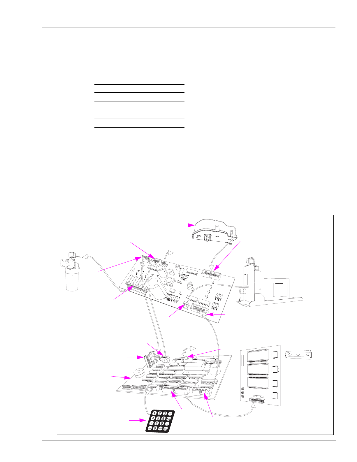
Component Overview Electronic and Electrical Components
Pulser (T18350-G3)
Main Display (T18981-G1)
2 Locations
Graphics Overlay (T17549-G1)
P204
Display Data
P205
P203
Manager’s
Keypad
Pump Controller
(T20092-G1)
P206
P207
P208
P-307
STP and Valve Signals from
the Pump Controller Board
P406
Driver Signals to
the Totalizers
P309
AC Signals to the
Valves and
STP/Motor Relays
P305
Handle Switch, Pulser Data to
the Pump Controller Board
and +5 VDC from the Pump
Controller Board
P308
24 VAC from the
Power Supply
Valve Feed and
Transformer
Assembly
Two-wire Data
P306
+14 VDC to
the Pump
Controller board.
P405
Handle Switch and Pulser Data
Main Power Supply (T19868-G1)
110 VAC to Valves and STPs
4.7 VAC to Display Backlights
Component Overview
Figure 5-2 shows the electronic components found in Atlas 8800 Retail unit. It is a typical
Atlas 8800 electronic system. For proper service,
the functions of components and how they relate to the system.
Part Number Description
T18350-G3 Pulser Assembly
T18994-G1 Hydraulic Interface PCA
T19868-G1 Main Power Supply
T20092-G1 Pump Controller PCA
T17701-G1
~ OR ~
T18981-G1
LCD Main Display PCA
While learning to operate the system, use a copy of this illustration for reference until you are
completely familiar with the system. This information is supplied with the Service Launch
Package. The prime functions of boards, devices, and service details are covered in
“Hydraulic/Mechanical Components” on page 5-1.
the technician must possess knowledge of
Figure 5-2: Atlas 8800 Electronics Retail Unit
MDE-4334D Atlas™ Start-up and Service Manual · July 2013 Page 5-11
Page 72

Electronic and Electrical Components PCAs
M07588A002 115 VAC without backup battery
M07588A001 115 VAC with backup battery
Atlas 9800
Power Supply Board
P3 - AC Input
C06387 LCD Display Board
M12158A00X LCD/Backlight Assembly.
P1: +5 VDC
Power Fail
Battery and
Ground to CPU
K-Pump RS-485 Board
M06725A001 with Totalizer output
M05248A001 with Totalizer output
C06389 Standard
(M06587A001) or K-Pump Pulse-out with Totalizer Boards (M05158A00X)
(M06333KXXXX)
Atlas 9800 CPU Board
P14: Serial Peripheral I/F
P9: ISB PWR/GND
JP1-JP9
P11: Display Power
and Data
P10: DC Power Input
shows the interface that relates assemblies and components for the main display
SW2
P1 - Hose 1 Valves and STP
P2 - Hose 2 Valves and STP
P3 - Pulser 1
P5 - Pulser 2
P4 - Handle switches
P2: +7.5 VDC
Power to display
Back lights and
Electromechanical
Totalizers
P8 RS-485 I/F
or
Pulse-out I/F
P6 - Totalizer
Sensor Intput
P7 Relay
Drive
Connection to
the CPU bd.
Connection to
the CPU bd.
Atlas 9800 Pulse-out I/F with EM Totalizer Drive Board
M07588A003 230 VAC with backup battery
M07588A004 230 VAC without backup battery
PCAs
This section provides information specific to PCAs.
Atlas 9800 PCAs
PCAs control the hydraulics and monitor the fuel delivery, compute, and display store
transaction information, interface with FMS. The term PCA and PCB may be interchanged
suitably.
Note: For proper service of PCAs, the technician must possess knowledge of the
components and how they relate to the system.
functions of
Figure 5-3 shows the interface that relates assemblies and c
omponents for the main display
PCA [see Figure 5-2 (on page 5-11) and Figure 5-32 (on page 5-39)].
Figure 5-3: Atlas 9800 Series Block Diagram
Page 5-12 MDE-4334D Atlas™ Start-up and Service Manual · July 2013
Page 73

PCAs Electronic and Electrical Components
U8 Programmed IC
(Software)
Figure 5-4 contains information regarding LEDs, hose information, switch locations, and
Random Access Memory (RAM) connections for previous Atlas 9800K CPUs.
M05346A002 (Dual, 115 VAC) and M05346A004 (Dual, 230 VAC):
Used on Models 9852K, 9853K, 9840K.
C06394 (Dual, 115 VAC) and C06503 (Dual, 230 VAC):
Used on Models 9850K, 9850A/Q, 9852A/Q, 98
53A/Q, 9840A/Q, 9822A/Q, 9823A/Q/K.
Note: This PCA is only used for 9800 serie
Figure 5-4: Previous Atlas 9800K CPU (M05346A00X, C06391-C06394, C06500-C06503)
s Commercial pumps.
MDE-4334D Atlas™ Start-up and Service Manual · July 2013 Page 5-13
Page 74

Electronic and Electrical Components PCAs
Fuses
(13070-07)
Hose 1
Hose 2
Valve and STP Relays
(Non-replaceable)
Authorization and
Relay LEDs
+3.3 V LED
+5 V LED
TP4, TP5 and TP6
(DC Voltage Test Points)
Pulser and
Handle LEDS
Fuses
(13070-07)
Previous Atlas 9800K CPU Software Kits
Dispenser or Pump Type Conversion Factor PCB Used On Software
Standard 9800K Gallons M05346A001 -
M05346A004 CPUs
C06500 -
C06503
Electronic
Commercial Uni
Standard 9800K Liters M03946K002
Standard 9800K Imperial Gallons M03946K003
Super-Hi 9840K Gallons M03946K004
ts
Super-Hi 9840K Liters M03946K005
Super-Hi 9840K Imperial Gallons M03946K006
Ultra-Hi 9850K Gallons C06391 - C06394,
Ultra-Hi 9850K Liters C06426K9850L
Ultra-Hi 9850K Imperial Gallons C06426K9850M
Figure 5-5 contains information regarding LEDs, hose information, switch locations, and jump
jack locations on the current Atlas 9800 CPU.
Notes: 1) M06333KXXXX requires an Atlas 9800 Power Supply (M07588A00X).
2) M06333KXXXX requires ATC Kit (M08218K001) for Models 9850A/Q, 9850K,
9852A/Q, 9853A/Q, 9840A/Q, where ATC is present.
M03946K001
C06426K98
50G
M06333KXXXX (Dual, 115/230 VAC)
Used on Models 9852K, 9853K, 9850K, 9840K, 9852A/Q, 9853A/Q, 9850 A/Q, 9840A/Q,
9822A/Q, 9823A/Q/K
Figure 5-5: Current Atlas 9800 CPU (M06333KXXXX)
.
Page 5-14 MDE-4334D Atlas™ Start-up and Service Manual · July 2013
Page 75

PCAs Electronic and Electrical Components
P2 - +7.5 VDC Power to Display
Backlights and Electro-mechanical
Totalizers
TP3
TP2
TP1
P1 - +5 VDC
Power Fail
Battery and
Ground to
CPU
P3 - AC Input
Current Atlas 9800 CPU Software Kits
Conversion
Dispenser or Pump Type
Standard 9800K
(Models: 9852K, 9853K)
Ultra-Hi 9850
(Models: 9850A/Q, 9850K)
Electronic
Commercial Unit
*Atlas 9800 Serial EEPROM Boards (M06656K00X) are used for reprogramming CPU Boards (M06333KXXXX).
tware Kit (M06656K100) contains parts M06656K001 - M06656K006 (one of each).
Sof
Super-Hi 9840K (Model:
s
9840K)
Standard 9800Q
(Models: 9852A/Q,
9853A/Q, 9822A/Q,
9823A/Q/K)
Super-Hi 9840Q (Model:
9840A/Q)
Standard 9860 and 9870
(Models: 9862KX, 9872KX)
Figure 5-6 shows the Atlas 9800 Power Supply Board (M07588A00X) that connects to the
CPU.
Factor PC
Selectable at
M06333KXXXX
CPU
M06333K9800K CPU M06656K001*
M06333K9850 CPU M06656K002*
M06333K9840K CPU M06656K003*
M06333K9800AQ
CPU
M06333K9840AQ
CPU
M06333KECAL M06656K006*
B Used On Software
M06656K004*
M06656K005*
Figure 5-6: Atlas 9800 Power Supply (M07588A00X)
MDE-4334D Atlas™ Start-up and Service Manual · July 2013 Page 5-15
Page 76

Electronic and Electrical Components PCAs
TP1
P6 (Totalizer)
P7 (Relay Drive)
P8 (RS-485/Pulser I/F)
P10 (Power Input)
P11 (LCD Display)
Switch 1
Switch 2
TP2
P1 (Hose 1 AC)
P2 (Hose 2 AC)
P3 (Pulser 1)
P4 (Handles)
P5 (Pulser 2)
P9 (ISB PWR/GND)
P10
P11
P14
(Serial
Peripheral I/F)
JP 1-9
SW2, 1-10
P12 (Not Used)
P5
P4
P3
P2
P1
P6
P7
P8
P9
TP4
(+3.3 V)
TP5
(GND)
TP6
(+5 V)
P18
Figure 5-7 shows the previous Atlas 9800K CPU.
Figure 5-7: M05346A002 (115 VAC) and M05346A004 [230 VAC (Previous Atlas 9800K
CPUs)]
Figure 5-8: Current Atlas 9800 CPU (M06333KXXXX)
Note: For cable block diagram, refer to M05193.
Page 5-16 MDE-4334D Atlas™ Start-up and Service Manual · July 2013
Page 77

PCAs Electronic and Electrical Components
P802
P804
P803
P2
P1
P1
P802
P804
P803
M05248A001
M06725A001
PCA Connections and Cables
Connector # Through Cabl e To Assembly At Connector #
P1 (6) P/O M04850A008
P2 (6) P/O M04850A008
P3 (4) Pulser 1
P5 (4) Pulser 2 Pulser Side B
P4 (4) M05105A001
P6 (2) M05119A001 Q12514-13 Sensor
P7 (3) Relay K1 (3) and (4)/Relay K2 (3) and (4)
P8 (14) M06725A001 P2 (14) CPU
P9 (6) Not Used
P10 (3) M05107A001 M07588A00X Atlas 9800 Power Supply
P11 (26) M05109A001 C06387 or M12158A00X P1 Side A and
P18 (3) M00150A003 or M00150A004 ECAL Security Switches (DEF or E85
M05201A001(Cable) Pulser (8) M04011B001 (cable)
Q12514-10 Pump Handle Switch A1 PH (B1) (4)
Q12514-10 Pump Handle Switch B1 PH (A1) (4)
AC-DC
P1 Side B
)
Only
Pulser Side A
P1 (5)
P1 (26)
Figure 5-9: K-pump RS-485 with Totalizer
Note: For cable block diagram, refer to M05193.
MDE-4334D Atlas™ Start-up and Service Manual · July 2013 Page 5-17
Page 78

Electronic and Electrical Components PCAs
P802
P804
P803
P1
P2
PCA Connections and Cables
Connector # Through Cable To Assembly At Connector #
P1 (4) M05189A002 Field Wiring Main J-box
P2 (14) Direct Connect M05346A002 (115 VAC) or
230 V
M05346A004 (
M06333KXXXX (115/230 VAC)
P802 (2) M00455A002 Side A
P803 (2) M00455A002 Side B
P804 (3) M05108A001
C06372 or M12019A001
2 Connections Side A
2 Connections Side B
M07588A00X P2 (3)
AC) or
Figure 5-10: C06425, C06746 - 9800 Pump I/F
P8 (14)
P1 (3)
Figure 5-11: M05158A001/2/3 - K-pump Pulse-out with Totalizer
Page 5-18 MDE-4334D Atlas™ Start-up and Service Manual · July 2013
Page 79

PCAs Electronic and Electrical Components
Part Number Where Used
M05158A001 T
M05158A002 To be used with all models (except 9850A/Q/K) calling out for Dual
M05158A003 T o be used with all models (except 9850A/Q/K) requiring only EM Totalizer ,
Note: Models 9850A/Q/K can only use M06587A001, C06425, or C06746.
o be used with all models (except 9850A/Q/K) calling out for Single
Channel, Dual/Single Hose Pulse-out I/F (see Figure 5-27 on page 5-36).
Channel, Single Hose Pulse-out I/F (see Figure 5-26 on page 5-35).
no Pulse-out I/F.
Figure 5-12: Atlas 9800 Pulse-out I/F with EM Totalizer Board (M06587A001)
Notes: 1) To be used with models calling out for Dual Channel, Dual Hose Pulse-out I/F (9850
Dual Hose requires M05683A004 Revision B or later).
2) M06587A001 Pulse-out I/F replaces the following 9800 Pump I/F Boards:
• Single Channel, Dual/Single Hose Puls
e-out I/F Board, C06425.
• Dual Channel, Single Hose Pulse-out I/F Board, C06746.
3) For cable block diagram, refer to M05193.
PCA Connections and Cables
Connector # Through Cable To Assembly At Connector #
P1 (4) M05189A002 Field Wiring Main J-box
P2 (14) Direct Connect M05346A002 (115 VAC) or
P802 (2) M00455A002 Side A
P803 (2) M00455A002 Side B
P804 (3) M05108A001 C06372 or M12019A001
46A004 (23
M053
M06333KXXXX
2 Connections Side A
2 Connections Side B
M07588A00X P2 (3)
0 VAC) or
P8 (14)
P1 (3)
MDE-4334D Atlas™ Start-up and Service Manual · July 2013 Page 5-19
Page 80

Electronic and Electrical Components PCAs
P1
Figure 5-13 shows the C06372 Backlight for the main LCD Display Board.
Figure 5-13: C06372 Main Display Backlight (Atlas 9800 Only)
Figure 5-14 shows the new Main Display Backlight Board (M12019A001).
Figure 5-14: New Main Display Backlight (Atlas 9800 Only)
Figure 5-15 shows C06387 LCD Display Board. In Figure 5-3 on page 5-12, the C06387 LCD
Display Board has been shown to connect to the CPU.
Figure 5-15: C06387 Atlas 9800 LCD Display Board
Page 5-20 MDE-4334D Atlas™ Start-up and Service Manual · July 2013
Page 81

PCAs Electronic and Electrical Components
K2, K4, K5, K6, K7
Decimal Point/Comma Jumpers
K1 - Side Select Jumper
Hose/Side 1 - Jumper Pins 1 and 2
Hose/Side 2 - Jumper Pins 2 and 3
Figure 5-16 shows the new Super Cap Main Display Board (M11714A00X).
Figure 5-16: New Super Cap Main Display (Atlas 9800 Only)
Display K2 K4 K5 K6 K7
000000 OFF OFF OFF OFF OFF
00000.0 ON OFF OFF OFF OFF
0000.00 OFF ON OFF OFF OFF
0000,00 OFF ON ON OFF OFF
000.000 OFF OFF OFF ON OFF
000,000 OFF OFF OFF ON ON
MDE-4334D Atlas™ Start-up and Service Manual · July 2013 Page 5-21
Page 82

Electronic and Electrical Components PCAs
P1401
P1405B
P2402
P1405AP1400
CR1
+24 V
CR5
Frozen
CR3 No
Fault A
CR2 No
Fault B
P2110
CR4
+5 V
P2112
Figure 5-17 shows Coriolis Interface Board (M10030A001).
Figure 5-17: Coriolis Interface Board [M10030A001 (At las DEF Only)]
PCA Connections and Cables (Cold Weather DEF)
Connector # Through Cable To Assembly At Connector #
P1400 (6) M04114A007 Temperature Sensor (Frozen) (M10131A008) PTRMF (3)
E
P1401 (3) M04114A007 to
2264A001
M1
P1405A (6) M04114A007 Coriolis Meter (M10006A003) J1501A/B (6)
P1405B (6) Not used
P2110 (7) M1 0059A002 Atlas CPU (M06333A002) P9 (6)
P2112 (8) M1 0060A001 to
5201A001
M0
P2402 (2) M07141A003 +24 V Power Supply (M04161B005) Red - (+)
2 Temperature Control Board (M06783A001) P1301A (10)
A
tlas CPU (M06333A002) P3 and P5 (4)
PCA Connections and Cables (Warm Weather DEF)
Connector # Through Cable To Assembly At Connector #
P1400 (6) Jumper Pins 5 and 6
P1401 (3) Not used
P1405A (6) M04114A008 Coriolis Meter (M10006A003) J1501A/B (6)
P1405B (6) Not used
P2110 (7) M10059A002 Atlas CPU (M06333A002) P9 (6)
P2112 (8) M10060A001 to
P2402 (2) M07141A003 +24 V Power Supply (M04161B005) Red - ( +)
M05201A001
Atlas CPU (M06333A002) P3 and P5 (4)
Black - (-)
Black - (-)
Page 5-22 MDE-4334D Atlas™ Start-up and Service Manual · July 2013
Page 83

PCAs Electronic and Electrical Components
P3
P2
CR1
Fan Active
CR2
Heater
Active
P1301A
Figure 5-18 shows E2 Temperature Control Board (M06783A001).
Figure 5-18: E2 Temperature Control Board [M06783A001 (Atlas Cold Weather DEF
Only)]
PCA Connections and Cables (Cold Weather DEF)
Connector # Through Cable To Assembly At Connector #
P2 (4) M12261A001 to
P3 (3) M12263A001 to
P1301A (6) M12264A001 to
M12202A001 to
M07233A003
M09958A003
M04114A007
This assembly mounts directly to a Solid-state Relay (Q11008-02).
ater/Fan Assembly (Q13254-03) P2082 (6)
He
AC Power Input AC J-box (3)
Coriolis Interface (M10030A001) J1401 (3)
Temperature Sensor (M10131A006) PTRMH (3)
MDE-4334D Atlas™ Start-up and Service Manual · July 2013 Page 5-23
Page 84

Electronic and Electrical Components PCAs
P1
D3 SLOW1
JJ1, JJ2, JJ3
P2402
D1 +24 V
D4 FAST1
D5 SLOW2
D2 +5 V
JJ4, JJ5, JJ6
D6 FAST2
P2
P7105
Component Side
Solder Side
Figure 5-19 shows Valve Interface Board (M11480A001).
Figure 5-19: Valve Interface Board [M11480A001 (Atlas E85 Only)]
PCA Connections and Cables (Atlas E85 Only)
Connector # Through Cable To Assembly At Connector #
P1 (4) M04850A010 Atlas CPU (M06333A002) P1 (6)
P2 (4) M04850A010 Atlas CPU (M06333A002) P2 (6)
P2402 (2) M07141A003 +24 V Power Supply (M04161B005) Red - (+)
P7105 (26) Cable on M06031A001 Valve Controller (M06031A001) P6105 (26)
Due to different tolerances in components and proportional valve coils, jump jacks JJ1 through
JJ6 (JJ1 through JJ3 affect side 1, JJ4 through JJ6 affect side 2) were added to allow adjusting
the SLOW flow rate. If the SLOW flow rate is too slow , add ing a jumper on one of these jump
jacks will increase the valve drive output in SLOW flow mode. Each jumper added increases
the drive output (maximum 3 per hose outlet). They do not affect FAST (or full) flow. If
jumpers have been added and the SLOW flow is too fast (for example, over run of presets),
removing a jumper will decrease the drive output in SLOW flow mode.
Black - (-)
Page 5-24 MDE-4334D Atlas™ Start-up and Service Manual · July 2013
Page 85

Atlas 9800 Parts Electronic and Electrical Components
CR15 Valve One Active
P6101
P6103
P6102
P6104
CR17
Valve Two
Active
P6105
Figure 5-20 shows Valve Controller Board (M06031A001).
Figure 5-20: Valve Controller Board [M06031A001 (Atlas E85 Only)]
PCA Connections and Cables (Atlas E85 Only)
Connector # Through Cable To Assembly At Connector #
P6101 (4) M11717A001 M02958A002 Valve Coil (Side 1)
Atlas 9800 Parts
Atlas 9800 CPU Board (M06333KXXXX)
P6102 (4) M11717A001 M02958A002 Valve Coil (Side 2)
P6103 (4) Not used
P6104 (4) Not used
P6105 (4) Cable on M06031A001 M11480A001 Valve Interface P7105 (26)
The features of the Atlas 9800 CPU Board are as follows:
• Accepts either 115 or 230 VAC on AUTH line inputs.
• Compatible with models 9852K, 9853K, 9850K, 98
9840A/Q, 9822A/Q, 9823A/Q/K, 9862KX, 9872KX.
• Compatible with all RS-485 I/F Boards (C06389, M05248A001, M06725A001).
• Compatible with all Pulse-out I/F Boards (C06425, C06746, M05158A001,
58A002, M05158A003, M06587A001).
M051
• Replaces 9800 CPU Boards: C06391, C06392, C06393, C06394, C06500, C06501,
C0650
2, C06503, M05346A001, M05346A002, M05346A003, M05346A004.
40K, 9852A/Q, 9853A/Q, 9850A/Q,
MDE-4334D Atlas™ Start-up and Service Manual · July 2013 Page 5-25
Page 86

Electronic and Electrical Components Atlas 9800 Parts
The ON position
(Closed) of the switch
is towards the center
of the board.
Always remove AC power from the pump/dispenser before servicing the unit. Failure to
turn off the unit before servicing may result in serious injury or death.
WARNING
• Requires new power supply M07588A00X (refer to “Atlas 9800 Power Supply
(M07588A00X)” on pa
ge 5-28).
• Requires ATC Kit (M08218K0 01), for models 9850A/Q, 9850K, 985 2A/Q, 9853A/Q, and
9840A/Q, where AT
Figure 5-21: Atlas 9800 CPU Board (M06333KXXXX)
C is present.
CPU Boards Software Type Pump Type
M06333K9800K 9800K 9852K, 9853K
M06333K9850 9850 9850A, 9850Q, 9850K
M06333K9840K 9840K 9840K
M06333K9800AQ 9800Q 9852A/Q, 9853A/Q, 9822A/Q, 9823A/Q/K
M06333K9840AQ 9840Q 9840A, 9840Q
M06333KECAL 9800K ECAL 9862KX, 9872KX
Note: The above software types can be loaded on any one of the M06333KXXXX
using the appropriate M06656K00X Serial EEPROM Board.
CPU Boards b
y
Loading New CPU Software (M06333KXXXX)
The CPU Board is configured and programmed before shipping from the factory. In the event
the software requires to be changed, proceed as follows:
1 Disconnect AC power to the pump/dispenser . Remove the DC ca ble from t he P1 conn ecto r on
the power supply .
2 Set Switch SW2-9 to the closed (“On”) position.
3 Select the appropriate Atlas 9800 Serial EEPROM Board (M06656K00X) for the software
type you want to load (refer to “Atlas 9800 Serial EEPROM Board (M06656K00X)” on
ge 5-29).
pa
Page 5-26 MDE-4334D Atlas™ Start-up and Service Manual · July 2013
Page 87

Atlas 9800 Parts Electronic and Electrical Components
4 Ensure that JP1 is not jumpered on the Serial EEPROM Board Assembly (M06656K00X).
Carefully insert into the P14 connector located in the middle of the CPU Board.
5 Connect the DC cable to the P1 connector on the power supply. Connect AC power to the
pump/dispenser.
6 At this point, on the Serial EEPROM Board Assembly , the green “PWR” and yellow “BUSY”
LEDs will illuminate. A few seconds later, the yellow “BUSY” LED will go off and green
“OK” LED must illuminate, indicating download is OK. Ensure that the “OK” LED is lit
before proceeding. If the red “NOT OK” LED illuminates, repeat steps 1 (on page 5-26) to 6.
If the “NOT OK” LED illuminates after a second attempt, call your service represe
ntative or
contact Gasboy Technical Service.
7 Disconnect AC power to the pump/dispenser . Remove the DC ca ble from t he P1 conn ecto r on
the power supply.
8 Set Switch SW2-9 to the Open position.
Note: If SW2-9 is left in the Closed position, the unit wi
ll not display software version,
software type, and firmware version during power-up.
9 Carefully remove the Serial EEPROM Board assembly from the P14 connector.
10 Connect the DC cable to the P1 connector on the power supply.
11 Connect AC power to the pump/dispenser.
12
Ensure that the displayed software type is correct for the pump/dispenser model that the CPU
is installed in (refer to the following table):
Displayed Software Type Corresponding Pump Type
“9800 1” Corresponds to the 9800Q Software:
“9800 2” Corresponds to the 9800K Software:
“9840 1” Corresponds to the 9840Q Software:
“9840 2” Corresponds to the 9840K Software:
“9850” Corresponds to all 9850 Software:
9852A/Q, 9853A/Q, 9822A/Q, 9823A/Q/K
9852K, 9853K, 9862KX, 9872KX
9840A, 9840Q
9840K
9850A, 9850Q, 9850K
MDE-4334D Atlas™ Start-up and Service Manual · July 2013 Page 5-27
Page 88

Electronic and Electrical Components Atlas 9800 Parts
Power Supply Without Battery Backup
(M07588A002)
Power Supply with Battery Backup
(M07588A001)
Atlas 9800 Power Supply (M07588A00X)
The features of the Atlas 9800 Power Supply (M07588A00X) are as follows:
• Required for M06333KXXXX CPU Board (see Figure 5-21 on page 5-26).
• Compatible with models 9852K, 9853K, 9850K, 98
9840A/Q, 9822A/Q, 9823A/Q/K, 9862KX, 9872KX.
• Compatible with the following 9800 CPU Boards: C06391, C06392, C06393, C06394,
C0650
0, C06501, C06502, C06503, M05346A001, M05346A002, M05346A003,
M05346A004, and M06333KXXXX.
• Replaces previous 9800 power supplies as shown in the
Description Old Power Supply Part Number Replacement Power Supply Part Number
115 VAC with Battery C06397 M07588A001 (see Note 1 below)
115 VAC Without Battery C06396 M07588A002
230 VAC with Battery C06489 M07588A003 (see Note 2 below)
230 VAC Without Battery C06488 M07588A004
Figure 5-22: Atlas 9800 Power Supply (M07588A00X)
40K, 9852A/Q, 9853A/Q, 9850A/Q,
following table:
Notes: 1) This supply can no longer be manufactured. Replacement kits are available. For
115 VAC units, the kits are as follows:
Number of
Displays per Unit Kit Number
1 M12421K001
2 M12421K002
4 M12421K003
2) This supply can no longer be manufactured. Replacement kits are available. For
230 VAC units, the kits are as follows:
Number of
Displays per Unit Kit Number
1 M12422K001
2 M12422K002
4 M12422K003
Page 5-28 MDE-4334D Atlas™ Start-up and Service Manual · July 2013
Page 89

Atlas 9800 Parts Electronic and Electrical Components
Atlas 9800 Serial EEPROM Board (M06656K00X)
The features of the Atlas 9800 Serial EEPROM Board are as follows:
• Used to reprogram software on Atlas 9800 CPU Board [M06333KXXX
(see Figure 5-21 on page 5-26)].
Serial EEPROM
Board Software Type Pump Type
M06656K001* 9800K 9852K, 9853K
M06656K002* 9850 9850A, 9850Q, 9850K
M06656K003* 9840K 9840K
M06656K004* 9800Q 9852A/Q, 9853A/Q,
9822A/Q, 9823A/Q/K
M06656K005* 9840Q 9840A, 9840Q
M06656K006* 9800K ECAL 9862KX, 9872KX
*A kit of the latest versions of all of these boards is also
available as p
art nu
mber M06656K100.
• Provides LED indicators to monitor software transfer (Download OK and Download Not
OK).
X,
Figure 5-23: LED Indicators
MDE-4334D Atlas™ Start-up and Service Manual · July 2013 Page 5-29
Page 90

Electronic and Electrical Components Atlas 9800 Parts
Atlas 9800 Pulse-out I/F Board with EM Totalizer Drive (M06587A001)
The features of the Atlas 9800 Pulse-out I/F Board with EM Totalizer Drive are as follows:
• T o be used with models calling out for
Hose requires M05683A004 Revision B or later).
• This board assembly can be configured for use in one of the following pump/dispenser
config
urations:
- Dual Channel, Single Hose Pulse-out I/F (see Figure 5
- Single Channel, Dual/Single Hose Pulse-out I/F (see Figure 5-27 on page 5-36).
- Dual Channel, Dual Hose Pulse-out I/F (see Figure 5-28 on page 5-36).
• Compatible with models 9852K, 9853K, 9850K, 98
9840A/Q, 9822A/Q, 9823A/Q/K, 9862KX, 9872KX.
• Compatible with 9800 CPU Boards (C06391, C06392, C06393, C06394, C06500,
C065
01, C06502, C06503, M05346A001, M05346A002, M05346A003, M05346A004,
M06333KXXXX).
• Can be used in place of previous 9800 Pump I/F
Pulse-out I/F (C06746).
• Can be used in place of previous 9800 Pump I/F Board with Single Channel, Dual/S
Hose Pulse-out I/F (C06425).
Note: 9850A/Q/K models cannot use M05158A00X Boards. They can use M06587A001,
25, and C06746 Boards only.
C064
Dual Channel, Dual Hose Pulse-out I/F (9850 Dual
-26 on page 5-35).
40K, 9852A/Q, 9853A/Q, 9850A/Q,
Board with Dual Channel, Single Hose
ingle
Figure 5-24: Atlas 9800 Pulse-out I/F Board with EM Totalizer Drive (M06587A001)
Page 5-30 MDE-4334D Atlas™ Start-up and Service Manual · July 2013
Page 91

Accessing Electronic Components Electronic and Electrical Components
Always remove AC power from the pump/dispenser before servicing the unit. Failure to
turn off the unit before servicing may result in serious injury or death.
WARNING
K-pump RS-485 with Totalizer (M06725A001)
The features of K-pump RS-485 with Totalizer Board are as follows:
• Allows RS-485 communications between 9800 and a CFN system, TopKAT, or TopKAT
PLUS Electronic
• Compatible with 9852K, 9853K, 9850K, 9840
9822A/Q, 9823A/Q/K, 9862KX, 9872KX.
• Compatible with 9800 CPU Boards (C06391, C06392, C06393, C06394, C06500,
01, C06502, C06503, M05346A001, M05346A002, M05346A003, M05346A004,
C065
M06333KXXXX).
• Can be used in place of previous 9800 RS-485 I/F Board C06389 and M05248A001.
Figure 5-25: K-pump RS-485 with Tot alizer (M06725A001)
system.
K, 9852A/Q, 9853A/Q, 9840A/Q,
Accessing Electronic Components
To access the electronic components, proceed as follows:
1 Unlock and remove the front panel on the pump/dispenser.
2 Remove the two bolts/screws located over the tabs of the bezel assembly. Lift the bezel
assembly upwards and out to remove.
Note: For A and Q models with front load nozzle,
screws) before removing the bezel assembly.
3 Loosen the two screws that secure the display panel and remove them, if required, and pivot
the display panel down.
MDE-4334D Atlas™ Start-up and Service Manual · July 2013 Page 5-31
remove the nozzle boot plastic shroud (two
Page 92

Electronic and Electrical Components Installing Atlas 9800 Power Supply (M07588A00X)
Always remove AC power from the pump/dispenser before servicing the unit. Failure to
turn off the unit before servicing may result in serious injury or death.
WARNING
Installing Atlas 9800 Power Supply (M07588A00X)
To install the Atlas 9800 Power Supply (M07588A00X), proceed as follows:
1 Check the existing power supply. For the correct replacement part number, refer to
“Atlas 9800 Power Supply (M07588A00X)” on page 5-28.
2 Ensure that the AC power to the pump/dispenser has been disconnected.
3 Disconnect the AC power cable from the P3 connector. Disconnect the DC cables from the P2
and P1 connectors.
4 Unscrew and remove all screws that hold the power supply . Retain the screws for installing the
new power supply.
5 Remove the power supply. For models with plastic standoffs, after the screws have been
removed, carefully unsnap the power supply from the standoffs and remove it. Remove any
standoffs that may have remained on the power supply and place them back into the plate
where the power supply was mounted.
6 Install the new power supply on the standoffs. Ensure that the P1 connector is closest to the
CPU Board and P3 connector is away from the CPU. If the pump model is 9822 or 9823, the
P1 connector is closest to the pump handle assembly.
7 Reinstall the screws removed in step 4. For models with plastic standoffs, carefully push the
power supply onto the plastic standoffs before
8 Reconnect the following:
installing the screws.
• Cables and AC power to the P3 connector.
• Display Backlight to the P2 connector.
• CPU DC to the P1 connector.
Page 5-32 MDE-4334D Atlas™ Start-up and Service Manual · July 2013
Page 93

Installing Atlas 9800 CPU Board (M06333KXXXX) Electronic and Electrical Components
Always remove AC power from the pump/dispenser before servicing the unit. Failure to
turn off the unit before servicing may result in serious injury or death.
WARNING
Installing Atlas 9800 CPU Board (M06333KXXXX)
To install the Atlas 9800 CPU Board, proceed as follows:
1 Check the existing power supply. If the existing supply is not a M07588A00X Assembly, it
must be replaced. For additional information, refer to “Installing Atlas 9800 Power Supply
(M07588A00X)” on page 5-32.
2 Ensure that the AC power to the pump/dispenser has been disconnected. Remove the DC cable
from the P1 connector on the power supply.
3 If the pump/dispenser does not have ATC installed, proceed to step 4. If the model of the
pump/dispenser is one of the following - 985 0A/Q, 9850K, 9852 A/Q, 9853A/Q, 9840A/Q, the
AT
C support bracket (that holds the ATC black box) must be replaced. Use the kit
M08218K001 to install the new bracket.
4 If the pump/dispenser has an RS-485 or Pulse-out Interface Board, remove the screws that
secure the interface board and disconnect it from the existing CPU Board.
5 Disconnect all cables going to the connectors on the CPU Board. Ensure that you take note of
connectors and cables so that they can be reconnected to the correct connector.
6 Unscrew and remove all the screws holding the CPU Board. Retain the screws for installing
the M06333KXXXX CPU Board.
7 Remove the CPU Board. For models with plastic standoffs, carefully unsnap the CPU Board
from the standoffs and remove it. Remove any standoffs that may have remained on the CPU
Board and place them back into the plate where the board was mounted.
8 The M06333KXXXX CPU Board can be configured for various operating conditions using
the jumpers JP1 to JP9 and Switch SW2. Check these jumpers and switch settings and change,
if required. Jumper settings must be changed with the power to the pump/dispenser “Off”. The
M06333KXXXX CPU Board only reads new jumper settings during power-up. For detailed
information on Jumper and Switch Settings for the M06333KXXXX CPU, refer to
“Configuration Steps” on page 4-5.
9 Set the new CPU Board on the standoffs. Reinstall screws removed in step 6. For models with
plastic standoffs, en sure that the metal st andoffs
are under the mounting holes located between
P2 and P3, and the outside corner next to P5. Carefully push the new CPU Board onto the
standoffs before installing the screws.
10 Reconnect all the cables, P1 to P9, and P11, if applicable. Reconnect the DC cable to P10 of
the power supply.
MDE-4334D Atlas™ Start-up and Service Manual · July 2013 Page 5-33
Page 94

Electronic and Electrical Components Installing Atlas 9800 Pulse-out I/F with EM Totalizer Drive Board (M06587A001)
11 Apply power to the pump/dispenser and take note of the display(s). The first set of numbers
displayed will be the software version (for example, 06013), second set is the software type
(for example, 9800 1), and third set is the firmware version (for example, 01008).
Ensure that the displayed software type is correct for
the pump/dispenser model that the CPU
is installed in (refer to the following table). If it is, proceed to step 12. If not, proceed to
“Loading New CPU Software (M06333KXXXX)” on page 5-26.
Displayed Software Type Corresponding Pump/Dispenser Model
“9800 1” Corresponds to the 9800Q Software:
“9800 2” Corresponds to the 9800K Software:
“9840 1” Corresponds to the 9840Q Software:
“9840 2” Corresponds to the 9840K Software:
“9850” Corresponds to all 9850 Software:
12 Reassemble the pump/dispenser by proceeding to “Accessing Electronic Components” on
9852A/Q, 9853A/Q, 9822A/Q, 9823A/Q/K
9852K, 9853K, 9862KX, 9872KX
9840A, 9840Q
9840K
9850A, 9850Q, 9850K
page 5-31 and follow the steps in the reverse order.
Installing Atlas 9800 Pulse-out I/F with EM Totalizer Drive Board (M06587A001)
Jumpers JP1, JP2, and JP3
This board assembly can be configured for use in one of the following pump/dispenser
configurations:
• Dual Channel, Single Hose Pulse-out I/F (see Figure 5-26 on page 5-35).
• Single Channel, Dual/Single Hose Pulse-out I/F (see Figure 5-27 on page 5-36).
• Dual Channel, Dual Hose Pulse-out I/F (see Figure 5-28 on page 5-36).
Following chart shows the jumper settings and wires to c
configuration.
Check JP1 - JP3 jumpers and change them, if required. The jumper settings must be changed
only when the power to the pump/dispenser is removed, to protect the circuit that they are
connected to.
The default configuration is Single Channel, Dual/Single Hose Pulse-out I/F. When configured
for Dual Channel, Single Hose Pulse-out I/F, or Single Channel, Dual/Single Hose Pulse-out
I/F, the P3 connector is not connected.
onnect to in the J-box, based on the
Page 5-34 MDE-4334D Atlas™ Start-up and Service Manual · July 2013
Page 95

Installing Atlas 9800 Pulse-out I/F with EM Totalizer Drive Board (M06587A001) Electronic and Electrical Components
Pulse Side 1
Side 1B Output (Green)
Side 1A Output (Red)
Side 1A Return (Black)
Side 1A Return (White)
When configured for Dual Channel, Dual Hose Pulse-out I/F, the P3 connector is used.
Jumper Settings
Single Channel, Dual/Single
Hose Pulse-out I/F
(Default Setting)
Wire Color JP1 Position 1
JP2 Position 1
JP3 Open
Black No Connection Side 1B Return Side B Return
Blue** No Conn ection No Connection Pulse Out Side 2A*
Brown No Connection No Connection Pulse out Side 2A
Gray No Connection No Connection Side 2B Return
Green Pulse out Side 2 Pulse out Side 1B Pulse out Side 1B
Amber No Connection No Connection Pulse out Side 2B
Red Pulse out Side 1 Pulse out Side 1A Pulse out Side 1A
Violet** No Connection No Connection Pulse Out Side 2B*
White Common Return Side 1A Return Side A Return
Yellow No Connection No Connection Side 2A Return
*Requires DC conduit M05683A004 Revision B or later.
**9850K models only.
Dual Channel, Single Hose
Pulse-out I/F
JP1 Position 2
JP2 Position 2
JP3 Open
Dual Channel, Dual Hose
Pulse-out I/F
JP1 Position 2
JP2 Position 2
JP3 Jumpered
Jumpers JP4 and JP5
When this board is used in a model A or Q pump/dispenser or 9850K, jumpers JP4 and JP5 are
set to the Q/A position. When this board is used for all other K models except 9850K, these
jumpers must be in the K position.
Configurations
Refer to Figure 5-26 through Figure 5-29 on page 5-36 for different configurations.
Figure 5-26: Dual Channel, Single Hose Pulse-out I/F
MDE-4334D Atlas™ Start-up and Service Manual · July 2013 Page 5-35
Page 96

Electronic and Electrical Components
Pulse Side 1
Pulse Side 2
Side 1 Output (Red)
Side 2 Output (Green)
Common Return (White)
Pulse Side 1
Side 1A Output (Red)
Side 1B Output (Green)
Side 1A Return (White)
Side 1B Return (Black)
Pulse Side 2
Side 2A Output (Brown)
Side 2B Output (Amber)
Side 2A Return (Yellow)
Side 2B Return (Gray)
Pulse Side 1
Side 1A Output (Red)
Side 1B Output (Green)
Pulse Side 2
Side 2A Output (Blue)
Side 2B Output (Violet)
Side A Return (White)
Side B Return (Black)
Figure 5-27: Single Channel, Dual/Single Hose Pulse-out I/F
Figure 5-28: Dual Channel, Dual Hose Pulse-out I/F
Installing Atlas 9800 Pulse-out I/F with EM Totalizer
Drive Board (M06587A001)
Figure 5-29: Dual Channel, Dual Hose Pulse-out I/F on 9850KX Ultra-Hi
Page 5-36 MDE-4334D Atlas™ Start-up and Service Manual · July 2013
Page 97

Atlas 8800 Parts
AT_PumpPCA_interface
P306
P307 P406 P405
P309 P308 P305
Atlas 8800 Parts
Pump Interface PCA [T18994 (Atlas 8800 Only)]
Pump Interface PCA (T18994) connects with the pump controller and pulsers, pump handle
switches, valves, STP signal relays, and electro-mechanical totalizers. Normally , this interface
is with the Pump Controller PCA. However, when an ATC Controller Board is used, the Pump
Controller Interface sends pulser information to the ATC Controller PCA. The Hydraulic
Interface (T18994) also converts the 24 VAC it receives from the power supply to 14 VDC for
the pump handle feed and 150 VDC for pulsers. The interface receives +5 VDC from the
Pump Controller PCA and supplies 120 VAC for the valve and STP signals.
C
Figure 5-30 shows the STP P
Interface, Pump Interface PCA (T18994-G1).
Figure 5-30: Pump Interface PCA [T18994 (Atlas 8800 Only)]
A layout that contains components related to the Hydraulic
Electronic and Electrical Components
PCA Connections and Cables
Connector # Through Cable To Assembly At Connector #
P305 (20) R19952-G1 T20092-G1 P205 (16)
P306 (5) R19939-G1 T20092-G1 P206 (5)
P307 (10) R19951-G1 T20092-G1 P207 (10)
P308 (2) 24 VAC R20333-G1
MDE-4334D Atlas™ Start-up and Service Manual · July 2013 Page 5-37
P309 (12) T19983 T19983-G1 P604 (4) P601 (3) P401
)
(9
M04658A001 Q12514-10 (A1)/Q12514-10 (B1) PH (A1) (4), PH (B1) (4)
0)
P405 (2
P406 (5) M04889A001
R19072-G1 T18350-G3 (A) T18350-G3 (B) J921B (4), J921A (4)
M04658A001 Q11763-01 (+) (C) (-)
M00455A003 Grade 1 J922A (4)
M00455A003 Grade 1 J922B (4)
Page 98

Electronic and Electrical Components Atlas 8800 Parts
P206
P207
P208
P201
P204
P203
P202
P205
JP1
AT_PumpPCA_controller
P206
P207
P208
P201
P204
P203
P202
P205
JP1
Pump Controller PCA [T20092 (Atlas 8800 Only)]
This PCA provides computation for the operation of the unit. It provides instructions to the
other boards for:
• Control of valves
• Displayed information
• Sale progression
• Sale calculations
•Totals memory
• Programming storage
Figure 5-31 shows the PCA of the Atlas
Retail Electronic system. For proper service, the
technician must possess knowledge of the functions of components and how they relate to the
system.
Figure 5-31: Pump Controller [T20092 (Atlas 8800 Only)]
T20092 Connections and Cables (with ATC)
Connector # Through Cable To Assembly At Connector #
P201 (10)
(Not used)
P202 (13)
(Not used)
P203 (10) R201461-G1 T20569-G1 P303 (10)
P204 (34) R19667-G1 T20569-G1 P304 (34)
P205 (16)
P207 (10)
P206 R19939-G1 T18994-G1 P306 (5)
Page 5-38 MDE-4334D Atlas™ Start-up and Service Manual · July 2013
M02739A001 T20569 P405 (34)
P301 (20)
P305 (34)
Page 99

Atlas 8800 Parts Electronic and Electrical Components
CR-2
Blink = Transmitting Data
CR-1
ON = Two-wire Reversed
CR-4
Blink = Receiving Data
CR-3
ON = CPU Running
JP-1 Jumper On at
Power Up = Master
Reset
Figure 5-32 shows the Hydraulic Interface that contains assemblies and components related to
customer information on the Pump Controller PCA (T20092-G1).
Figure 5-32: Atlas 8800 Pump Controller (T20092)
PCA Connections and Cables
Connector # Through Cable To Assembly At Connector #
P201 (10-pin) N/A N/A N/A
P202 (13-pin) N/A N/A N/A
P203 (10-pin) R19951-G1 T17549-G1 P901A (10)
P204 (34-pin) T17768-G1 T17701-G1 or T18981-G1,
P205 (16-pin) R19952-G1 T18994-G1 P305 (16)
P206 (5-pin) R19939-G1 T18994-G1 P306 (5)
P207 (10-pin) R19951-G1 T18994-G1 P307 (10)
P208 (3-pin) R20412-G3 J402 Field Wiring P402A (2)
This PCA contains a firmware chip that holds base instructions for the operation of the unit.
LEDs are provided to alert the technician during diagnostics, regarding POS problems,
processor function, or reversed polarity of the two-wire system feed wires.
The board receives +14 VDC from th e Hydraulic Interface PCA. Cus tomer programmable and
5-button preset as well as the Manager Keypad (except for ATC) are connected directly to this
PCA. It supplies +5 VDC to the Hydraulic Interface PCA.
t
andard LCD Display
S
P801 (34) (Side A)
(2 places) and (Side B)
(2 places)
P402 (3)
MDE-4334D Atlas™ Start-up and Service Manual · July 2013 Page 5-39
Page 100

Electronic and Electrical Components Atlas 8800 Parts
AT_ATC_GR4
P307
TP1
P405
P301
P305 S1
P415
P303
P303A
P304
P308
P204A
JP1
ATC Component Overview (Atlas 8800 Only)
The ATC PCA (T20569) and T-Meter Module ATC (T19405) are optional electronic
components. Examples of probes and meters used for temperature control are primarily for the
Canadian market. The ATC option measures the temperature of the dispensed products and
compensates for changes in the product volume due to changes in the ambient temperature.
The T-Meter Module PCA links the thermal probe in
the meter cover with t
he ATC PCA. An
Intrinsically Safe (I.S) barrier is used at the J-box between the T-Meter Module PCA and ATC
PCA.
115/230/380 VAC Single/Dual Unit with ATC PCA (T20569) and
Programmable Pump Preset (Option)
The ATC PCA (T20569) records the temperature-related input from the T-Meter Module
Hydraulic Interface PCA, which then modifies the pulser-count to regulate the temperature
change. The adjusted pulser-count is supplied to the Pump Controller PCA. Components for
the firmware are located near the center of the board at U5 and U11, which also contains the
battery-backed RAM. The PCA receives +5 VDC from the Pump Controller PCA and
14.5 VDC from the Pump Interface PCA. The ATC PCA also receives
Keypad before the Pump Controller PCA, which allows information to be entered through the
keypad for programming and testing purposes, when the ATC is us ed.
Figure 5-33: ATC PCA [T20569 (Atlas 8800 Only)]
data from the Manager
Page 5-40 MDE-4334D Atlas™ Start-up and Service Manual · July 2013
 Loading...