

Page 1

Introduction
Purpose
The purpose of the Single Standard Pump/Dispenser Inlet Centering Kit (M07676K00X) is to
provide a method for centering the product inlet on standard Atlas
during unit installation. This will provide the unit with a 2 inch NPT-centered connection, and
it can be used on Atlas single product or Twin 1 product (TW1) models.
Table of Contents
Topic Page
Introduction 1
Important Safety Information 3
Installation of the Kit 5
MDE-4637A
Single Standard Pump/Dispenser Inlet Centering
Kit (M07676K00X) Installation for Atlas
™
Units
August 2007
™
single product models
Kits
Part Number Description
M07676K001 Atlas Standard Dispenser Inlet Centering Kit
M07676K002 Atlas Standard Pump Inlet Centering Kit
Required Tools
The following tools are required for the installation of M07676K00X kits:
Parts List
The following table lists the parts included in the Single Standard Dispenser Inlet Centering
kit (M07676K001).
Item Description Part Number Quantity
1 Inlet Manifold M05347B010 1
2 M10 X 25 Socket Head Screw M04973B005 6
3 M10 Lock washer M01071B001 6
4 Gasket M06101B001 2
5 Dispenser Manifold Blanking Spacer M07671B001 1
• Allen Wrench, Metric
• Gloves, Rubber
• Grease, Silicone
• Ratchet Set, Metric
• Wrench Set, Metric Open-end
MDE-4637A Single Standard Pump/Dispenser Inlet Centering Kit (M07676K00X) Installation for Atlas™ Units · August 2007 Page 1
Page 2

Introduction
Item Description Part Number Quantity
6 M6 X 25 Flanged Screws M00415B016 3
The following table lists the parts included in the Single Standard Pump Inlet Centering kit
(M07676K002).
Item Description Part Number Quantity
1 Inlet Manifold M05347B010 1
2 M8 X 16 Flanged Screw M00415B009 2
3 M10 Lock washer M01071B001 6
4 M10 X 25 Socket Head Screw M04973B005 6
5 Gasket M06101B001 2
6 Pump Manifold Blanking Plate M07675B001 1
Related Documents
Document Number Title GOLD Library
MDE-4331 Atlas Fuel Systems Installation Manual Gasboy Commercial & Retail Pumps
MDE-4333 Atlas Fuel Systems Site Preparation Manual Gasboy Commercial & Retail Pumps
MDE-4334 Atlas Start-up/Service Manual Gasboy Commercial & Retail Pumps
Warranty
For information on warranty, refer to MDE-4255 Gasboy’s Warranty Policy Statement. If you
have any warranty-related questions, contact Gasboy’s Warranty Department at its Greensboro
location.
Page 2 MDE-4637A Single Standard Pump/Dispenser Inlet Centering Kit (M07676K00X) Installation for Atlas™ Units · August 2007
Page 3
Important Safety Information
This section introduces the hazards and safety precautions
associated with installing, inspecting, maintaining or servicing
this product. Before performing any task on this product, read
this safety information and the applicable sections in this
manual, where additional hazards and safety precautions for
your task will be found. Fire, explosion, electrical shock or
pressure release could occur and cause death or serious
injury if these safe service procedures are not followed.
Preliminary Precautions
You are working in a potentially dangerous environment of
flammable fuels, vapors, and high voltage or pressures. Only
trained or authorized individuals knowledgeable in the related
procedures should install, inspect, maintain or service this
equipment.
Important Safety Information
Read the Manual
Read, understand and follow this manual and any other
labels or related materials supplied with this equipment. If you
do not understand a procedure, call a Gasboy Authorized
Service Contractor or call the Gasboy Service Center at 1800-444-5529. It is imperative to your safety and the safety of
others to understand the procedures before beginning work.
Follow the Regulations
There is applicable information in NFPA 30A; Automotive and
Marine Service Code, NFPA 70; National Electrical Code (NEC),
OSHA regulations and federal, state, and local codes which
must be followed. Failure to install, inspect, maintain or
service this equipment in accordance with these codes,
regulations and standards may lead to legal citations with
penalties or affect the safe use and operation of the
equipment.
Emergency Total Electrical Shut-Off
The first and most important information you must know is
how to stop all fuel flow to the pump and island. Locate the
switch or circuit breakers that shut-off all power to all fueling
equipment, dispensing devices, and submerged turbine
pumps (STPs).
!
WARNING
!
The EMERGENCY STOP, ALL STOP, and
PUMP STOP buttons at the cashier’s station
WILL NOT shut off electrical power to the
pump/dispenser.
Total Electrical Shut-Off Before Access
Any procedure requiring access to electrical components or
the electronics of the dispenser requires total electrical shutoff of that unit. Know the function and location of this switch
or circuit breaker before inspecting, installing, maintaining, or
servicing Gasboy equipment.
Evacuation, Barricading and Shut-Off
Any procedures requiring accessing the pump/dispenser or
STPs requires the following three actions:
This means that even if you activate these
stops, fuel may continue to flow uncontrolled.
You must use the TOTAL ELECTRICAL SHUTOFF in the case of an emergency and not only
these cashier station “stops.”
Replacement Parts
Use only genuine Gasboy replacement parts and retrofit kits
on your pump/dispenser. Using parts other than genuine
Gasboy replacement parts could create a safety hazard and
violate local regulations.
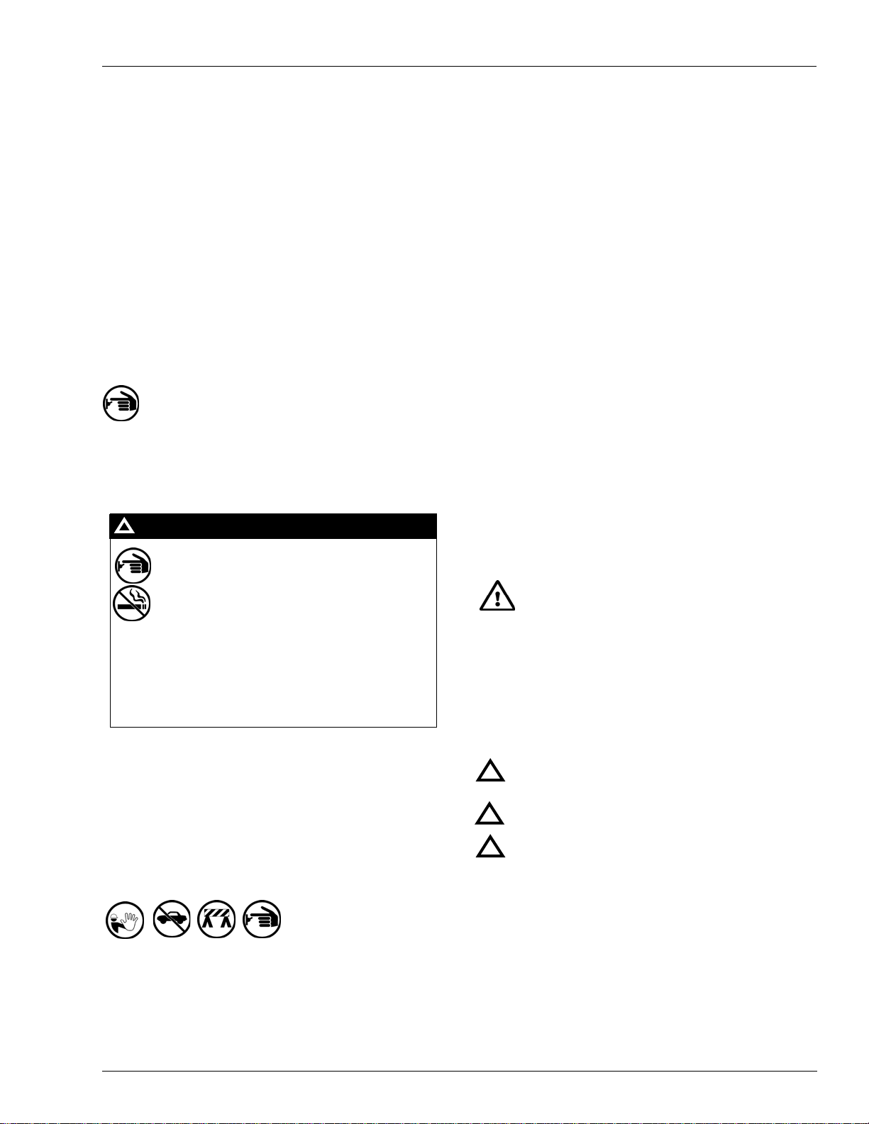
Safety Symbols and Warning Words
This section provides important information about warning
symbols and boxes.
Alert Symbol
This safety alert symbol is used in this manual and on
warning labels to alert you to a precaution which must be
followed to prevent potential personal safety hazards. Obey
safety directives that follow this symbol to avoid possible
injury or death.
Signal Words
These signal words used in this manual and on warning labels
tell you the seriousness of particular safety hazards. The
precautions that follow must be followed to prevent death,
injury or damage to the equipment
DANGER - This signal word is used to alert you to a
!
hazard to unsafe practice which will result in death or
serious injury
WARNING - This alerts you to a hazard or unsafe
!
practice that could result in death or serious injury.
CAUTION with Alert symbol - This signal word
!
designates a hazard or unsafe practice which may
result in minor injury.
CAUTION without Alert symbol - When used by itself,
CAUTION designates a hazard or unsafe practice
which may result in property or equipment damage.
- An evacuation of all unauthorized persons and vehicles
using safety tape, cones or barricades to the effected units
- A total electrical shut-off of that unit
MDE-4637A Single Standard Pump/Dispenser Inlet Centering Kit (M07676K00X) Installation for Atlas™ Units · August 2007 Page 3
Working With Fuels and Electrical Energy
Prevent Explosions and Fires
Fuels and their vapors will become explosive if ignited. Spilled
or leaking fuels cause vapors. Even filling customer tanks will
cause explosive vapors in the vicinity of dispenser or island.
Page 4

Important Safety Information
No Open Flames
Open flames from matches, lighters, welding
torches or other sources can ignite fuels and their vapors.
No Sparks - No Smoking
Sparks from starting vehicles, starting or using power tools,
burning cigarettes, cigars or pipes can also ignite fuels and
their vapors. Static electricity, including an electrostatic
charge on your body, can cause a spark sufficient to ignite
fuels and their vapors. After getting out of a vehicle, touch the
metal of your vehicle to discharge any electrostatic charge
before you approach the dispenser island.
Working Alone
It is highly recommended that someone who is capable of
rendering first aid be present during servicing. Be familiar
with Cardiopulmonary Resuscitation (CPR) methods if you
are working with or around high voltages. This information is
available from the American Red Cross. Always advise the
station personnel about where you will be working, and
caution them not to activate power while you are working on
the equipment. Use the OSHA tag out and lock out
procedures. If you are not familiar with this requirement, refer
to information in the service manual and OSHA
documentation.
Working With Electricity Safely
Be sure to use safe and established practices in working with
electrical devices. Poorly wired devices may cause a fire,
explosion or electrical shock. Be sure grounding connections
are properly made. Make sure that sealing devices and
compounds are in place. Be sure not to pinch wires when
replacing covers. Follow OSHA Lock-Out and Tag-Out
requirements. Station employees and service contractors
need to understand and comply with this program completely
to ensure safety while the equipment is down.
Emergency First Aid
Informing Emergency Personnel
• Compile the following information for emergency
personnel:
• Location of accident (for example, address, front/back of
building, and so on.)
• Nature of accident (for example, possible heart attack, run
over by car, burns, and so on.)
• Age of victim (for example, baby, teenager, middle-age,
elderly.)
• Whether or not victim has received first aid (for example,
stopped bleeding by pressure, and so on.)
• Whether or not a victim has vomited (for example, if
swallowed or inhaled something, and so on.)
WARNING
!
Gasoline ingested may cause unconsciousness
and burns to internal organs.
Do not induce vomiting.
Keep airway open.
Oxygen may be needed at scene.
Seek medical advice immediately.
WARNING
!
Gasoline inhaled may cause unconsciousness
and burns to lips, mouth and lungs.
Keep airway open.
Seek medical advice immediately.
WARNING
!
Gasoline spilled in eyes may cause burns to eye
tissue.
Irrigate eyes with water for approximately 15
minutes.
Seek medical advice immediately
Hazardous Materials
Some materials present inside electronic enclosures may
present a health hazard if not handled correctly. Be sure to
clean hands after handling equipment. Do not place any
equipment in mouth.
!
WARNING
This area contains a chemical known to the State of
California to cause cancer.
WARNING
!
This area contains a chemical known to the State of
California to cause birth defects or other reproductive
harm.
IMPORTANT: Oxygen may be needed at scene if gasoline
has been ingested or inhaled. Seek medical advice
WARNING
!
Gasoline spilled on skin may cause burns.
Wash area thoroughly with clear/water.
Seek medical advice immediately.
IMPORTANT: Oxygen may be needed at scene if gasoline
has been ingested or inhaled. Seek medical advice
immediately.
Lockout/Tagout
Lockout/Tagout covers servicing and maintenance of
machines and equipment in which the unexpected
energization or start up of the machine(s) or equipment or
release of stored energy could cause injury to employees or
personnel. Lockout/Tagout applies to all mechanical,
hydraulic, chemical or other energy, but does not cover
electrical hazards. Reference Subpart S of 29 CFR Part 1910
- Electrical Hazards, 29 CFR Part 1910.333 contains specific
Lockout/Tagout provision for electrical hazards.
immediately.
Page 4 MDE-4637A Single Standard Pump/Dispenser Inlet Centering Kit (M07676K00X) Installation for Atlas™ Units · August 2007
Page 5

Installation of the Kit
Note: The M07676K00X kits are installed at the time of initial unit installation. If the kits are
to be retrofitted onto units that are already in use, consult and follow MDE-4334 Atlas
Start-up/Service Manual for safety, purging, and shut-down procedures.
Installing the M07676K001 Kit on a Dispenser
To install the M07676K001 kit on a dispenser, proceed as follows:
1 Attach the manifold blanking spacer (M07671B001) to the underside of the existing inlet
support plate. Secure it with three flanged screws (M00415B016) and tighten.
2 Lightly apply grease to the bottom faces of both the blanking spacer and the existing dispenser
inlet casting.
3 Lightly apply some grease to both discharge flanges of the inlet manifold (M05347B010).
4 Attach the two gaskets (M06101B001) to the flanges in the mating position.
Installation of the Kit
Existing Single
Dispenser Inlet
Casting
5 With gaskets in place, attach the manifold to the dispenser inlet casting and secure using three
lockwashers (M01071B001) and three socket head screws (M04973B005). Tighten the screws
to a snug fit; do not overtighten.
6 Secure the opposite end of the manifold to the manifold blanking spacer using three
lockwashers (M01071B001) and three socket head screws (M04973B005).
7 Tighten all the six screws that attach the manifold to the inlet casting and blanking spacer.
8 Check for leaks upon initial operation of the unit.
M6 X 25 Flanged
Screws
(M00415B016)
Existing
Dispenser Inlet
Support Plate
Dispenser Manifold
Blanking Space
(M07671B001)
Gasket
(M06101B001)
Inlet Manifold
(M05347B010)
MDE-4637A Single Standard Pump/Dispenser Inlet Centering Kit (M07676K00X) Installation for Atlas™ Units · August 2007 Page 5
M10 X 25 Socket Head
Screw (M04973B005)
M10 Lock Washer
(M01071B001)
Page 6

Installation of the Kit
Installing the M07676K002 Kit on a Self-contained Pump
To install the M07676K002 kit on a self-contained pump, proceed as follows:
1 Remove the three bolts and lock washers that attach the existing pump inlet adapter and
gasket. Discard the adapter, gasket, and hardware.
2 Lightly apply some grease to both discharge flanges of the inlet manifold (M05347B 010).
3 Attach two gaskets (M06101B001) to the flanges in the mating position.
4 Lightly apply grease to the face of the existing pump inlet.
5 With the gasket in place, attach the manifold to the pump inlet and secure using three
lockwashers (M01071B001) and three socket head screws (M04973B005). Tighten the screws
to a snug fit; do not overtighten.
6 With the gasket in place on the manifold face opposite the pump, lightly grease the mating
face of the manifold blanking plate (M07675B001) and place it on top of the pump and motor
support plate.
Note: The manifold blanking plate is not symmetrical and will fit only one way when bolts are
attached.
7 Secure the manifold blanking plate to the manifold using three lockwashers (M01071B001)
and three socket head bolts (M04973B005). Tighten them to a snug fit; do not overtighten.
8 Secure the blanking plate to the underside of the pump and motor support plate using two
flanged screws (M00415B009) and tighten.
9 Tighten all the six screws that attach the manifold to the pump and blanking plate.
10 Check for leaks upon initial operation of the unit.
Page 6 MDE-4637A Single Standard Pump/Dispenser Inlet Centering Kit (M07676K00X) Installation for Atlas™ Units · August 2007
Page 7

Existing
Pumping Unit
(Remove
Existing Inlet
Adapter and
Gasket)
Installation of the Kit
Pump Manifold
Blanking Plate
(M07675B001)
Existing Pump
and Motor
Support Plate
Gasket
(M06101B001)
Inlet Manifold
(M05347B010)
M8 X 16 Flanged
Screws (M00415B009)
M10 X 25 Socket Head
Screw (M04973B005)
M10 Lock Washer
(M01071B001)
MDE-4637A Single Standard Pump/Dispenser Inlet Centering Kit (M07676K00X) Installation for Atlas™ Units · August 2007 Page 7
Page 8

Installation of the Kit
TM
Atlas
is a trademark of Gasboy Inc.
© 2007 GASBOY
7300 West Friendly Avenue •Post Office Box 22087
Greensboro, North Carolina 27420
Phone 1-800-444-5529 • http://www.gasboy.com • Printed in the U.S.A.
MDE-4637A Single Standard Pump/Dispenser Inlet Centering Kit (M07676K00X) Installation for Atlas™ Units · August 2007
 Loading...