

Page 1
Introduction
MDE-4548
Atlas™ Rain Baffle Air Gap
Kit M06804K002 Installation Instructions
February 2006
This document provides instructions for installing the rain baffle air gap kits on Atlas
electronic models when retrofitting an M06715 lower door panel onto units that previously
used the old style M04256 lower door panels. The M04256 lower door panel comprised a twopiece construction that provided a separation between the hydraulics and the air gap on
electronic models. The M06690B001 Rain Baffle Air Gap plate provides a rain shield for the
air gap vents and maintains air gap integrity by separating the hydraulics and the air gap when
using the one piece M06715 lower door panels.
Rain Baffle Air Gap Kits
Kit No. Description
M06804K002 Atlas Rain Baffle Air Gap Kit
Note: The kit must be added to any electronic model that had the 2-piece panel with riveted
air gap grill when changing to M06715 door.
Note: Rain baffle air gap plates are not required for mechanical models. M06715
panels for mechanical models do not have grills and will not fit on units with rain baffle
air gap plates.
WARNING
!
To maintain air gap integrity, all Atlas electronic models must have a rain baffle air
gap plate (M06690B001) on both sides when using an M06715B002, B102, B003,
or B103 lower door panels. M06715B001 or B101 must not be used on an electronic
model.
™
Required Reading
Before installing a kit, the installer must read, understand, and follow:
• This manual
• NFPA 30A, The Automotive and Marine Service Station Code
• NFPA 70, The National Electric Code
• Applicable federal, state and local codes and regulations
Failure to do so may adversely affect the safe use and operation of the equipment.
Note: This kit must be installed by a Gasboy Authorized Service Contractor (ASC) to ensure
warranty.
Required Tool
Socket wrench 13mm
MDE-4548 Atlas™ Rain Baffle Air Gap Kit M06804K002 Installation Instructions • February 2006 Page 1
Page 2
Parts List
Parts List for Atlas Rain Baffle Air Gap Kit M06804K002
Part Number Description Quantity per Kit
M06690B001 Rain Baffle Air Gap Plate 2
M00415B009 M8x16, Flanged Screws 4
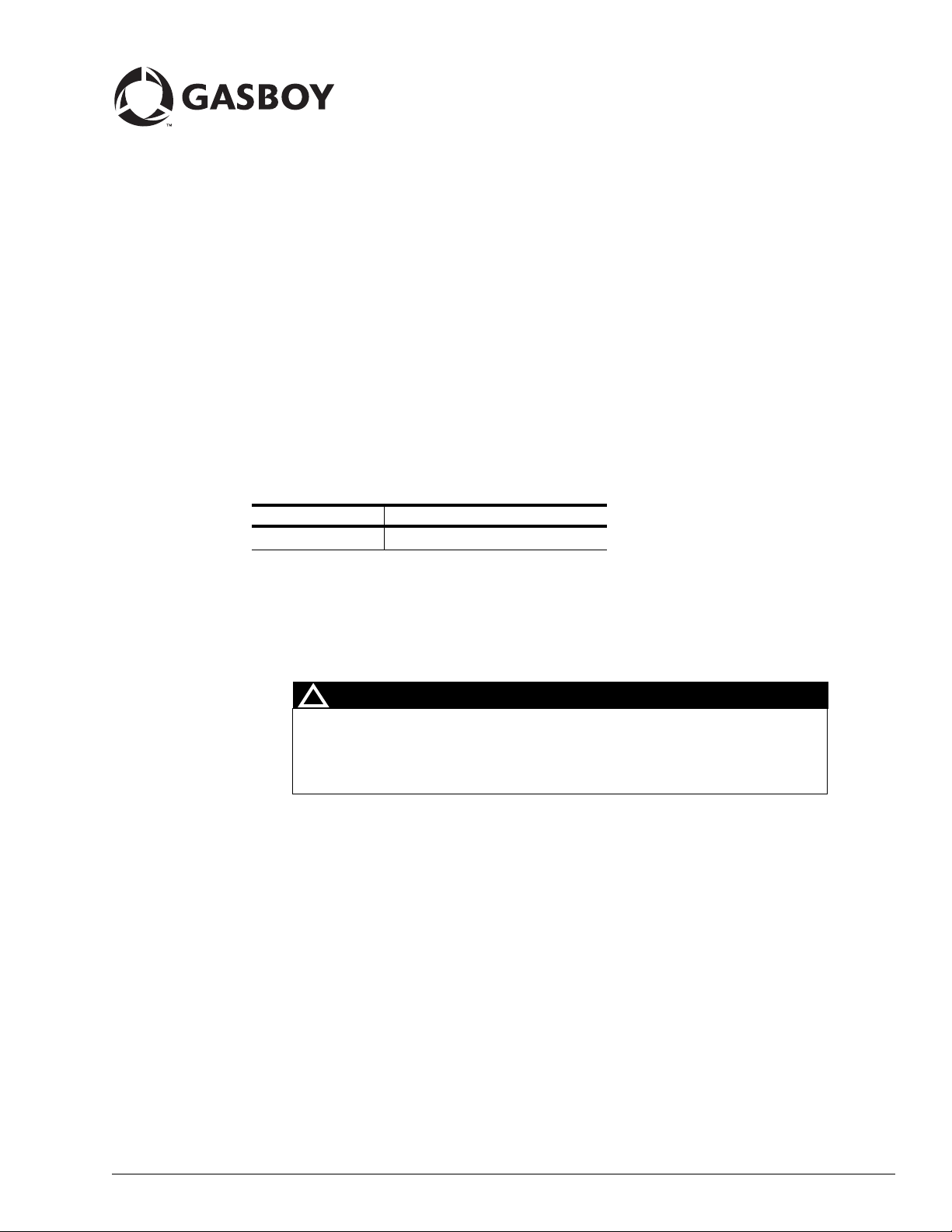
Figure 1: Rain Baffle Air Gap Plate
Slots for M8X16 Screws
New Lower Door Panels
The following are the new Lower Door Panels:
Door Panel Description Notes
M06715B001 Mechanical Model Panel,
M06715B002 Electronic Side-load Model Panel,
M06715B003 Electronic Front-load Model
M06715B101 Mechanical Model Panel, Painted
M06715B102 Electronic Side-load Model Panel,
M06715B103 Electronic Front-load Model
* Painted galvanized lower door panels (M06715B101, B102 and B103) must be ordered by
the painted graphics template number.
Stainless Steel
Stainless Steel
Panel, Stainless Steel
Galvanized Steel *
Painted Galvanized Steel *
Panel, Painted Galvanized Steel *
Does not have air gap grill - must not be
used on electronic models.
Unit must have rain baffle air gap plate
(M06690B001) added to each side.
Unit must have rain baffle air gap plate
(M06690B001) added to each side.
Does not have air gap grill - must not be
used on electronic models.
Unit must have rain baffle air gap plate
(M06690B001) added to each side.
Unit must have rain baffle air gap plate
(M06690B001) added to each side
Page 2 MDE-4548 Atlas™ Rain Baffle Air Gap Kit M06804K002 Installation Instructions • February 2006
Page 3
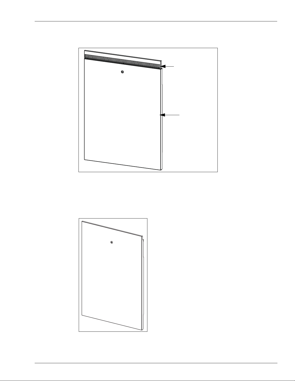
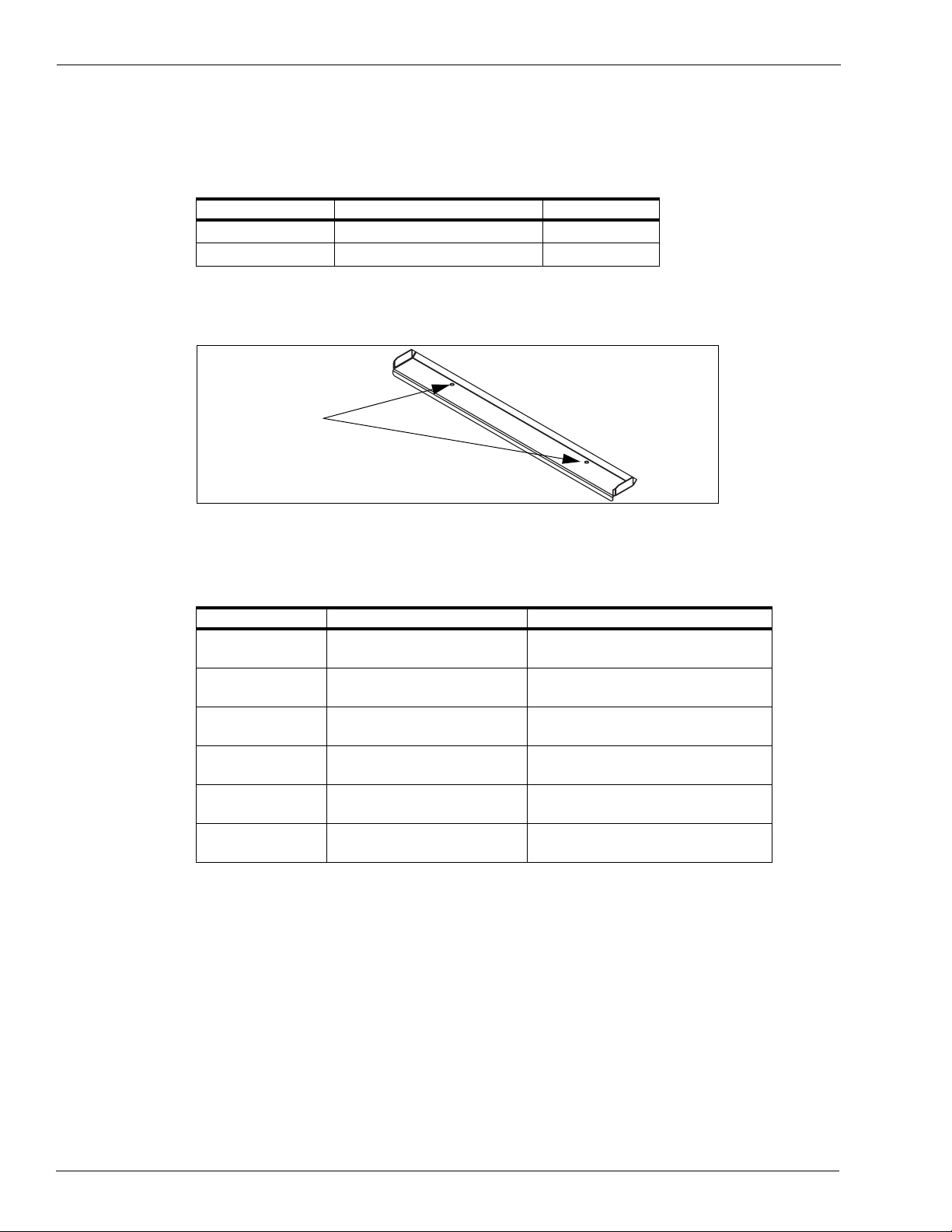
Figure 2: M04256 Old Lower Door Panel
Riveted Air Gap Grill
Lower Panel
Note: This door panel has a 2-piece panel with riveted air gap grill, and is no longer
available.
Figure 3: M06715B001 and B101 New Lower Door Panel (Mechanical Models Only)
Note: This lower door panel does not have an air gap grill and can be used in mechanical
models only.
MDE-4548 Atlas™ Rain Baffle Air Gap Kit M06804K002 Installation Instructions • February 2006 Page 3
Page 4

Figure 4: M06715B002 and B102 New Lower Door Panel (Electronic Side -mount Nozzle
Models)
Built-in Air
Gap Grill
Note: This lower door panel has a built-in air gap grill and can be used in electronic side-
mount nozzle models only.
Figure 5: M06715B003 and B103 New Lower Door Panel (Elect ronic Front-mount Nozzle
Models)
Built-in Air
Gap Grill
Note: This door panel has a built-in air gap grill and can be used in electronic front-mount
nozzle models only .
Page 4 MDE-4548 Atlas™ Rain Baffle Air Gap Kit M06804K002 Installation Instructions • February 2006
Page 5

Important Safety Information
Important Safety Information
This section introduces the hazards and safety precautions
associated with installing, inspecting, maintaining or servicing
this product. Before performing any task on this product, read
this safety information and the applicable sections in this
manual, where additional hazards and safety precautions for
your task will be found. Fire, explosion, electrical shock or
pressure release could occur and cause death or serious
injury if these safe service procedures are not followed.
Preliminary Precautions
You are working in a potentially dangerous environment of
flammable fuels, vapors, and high voltage or pressures. Only
trained or authorized individuals knowledgeable in the related
procedures should install, inspect, maintain or service this
equipment.
Emergency Total Electrical Shut-Off
The first and most important information you must know is
how to stop all fuel flow to the pump and island. Locate the
switch or circuit breakers that shut-off all power to all fueling
equipment, dispensing devices, and submerged turbine
pumps (STPs).
!
WARNING
!
The EMERGENCY STOP, ALL STOP, and
PUMP STOP buttons at the cashier’s station
WILL NOT shut off electrical power to the
pump/dispenser.
Read the Manual
Read, understand and follow this manual and any other
labels or related materials supplied with this equipment. If
you do not understand a procedure, call a Gasboy Authorized
Service Contractor or call the Gasboy Service Center at
1-800-444-5529. It is imperative to your safety and the safety
of others to understand the procedures before beginning
work.
Follow the Regulations
There is applicable information in NFPA 30A; Automotive and
Marine Service Code, NFPA 70; National Electrical Code (NEC),
OSHA regulations and federal, state, and local codes which
must be followed. Failure to install, inspect, maintain or
service this equipment in accordance with these codes,
regulations and standards may lead to legal citations with
penalties or affect the safe use and operation of the
equipment.
Replacement Parts
Use only genuine Gasboy replacement parts and retrofit kits
on your pump/dispenser. Using parts other than genuine
Gasboy replacement parts could create a safety hazard and
violate local regulations.
Safety Symbols and Warning Words
This section provides important information about warning
symbols and boxes.
Alert Symbol
Total Electrical Shut-Off Before Access
Any procedure requiring access to electrical components or
the electronics of the dispenser requires total electrical shutoff of that unit. Know the function and location of this switch
or circuit breaker before inspecting, installing, maintaining, or
servicing Gasboy equipment.
Evacuation, Barricading and Shut-Off
Any procedures requiring accessing the pump/dispenser or
STPs requires the following three actions:
- An evacuation of all unauthorized persons and vehicles
using safety tape, cones or barricades to the effected units
- A total electrical shut-off of that unit
This means that even if you activate these
stops, fuel may continue to flow uncontrolled.
You must use the TOTAL ELECTRICAL SHUTOFF in the case of an emergency and not only
these cashier station “stops.”
on warning labels to alert you to a precaution which must be
followed to prevent potential personal safety hazards. Obey
safety directives that follow this symbol to avoid possible
injury or death.
Signal Words
These signal words used in this manual and on warning
labels tell you the seriousness of particular safety hazards.
The precautions that follow must be followed to prevent
death, injury or damage to the equipment.
This safety alert symbol is used in this manual and
DANGER: Alerts you to a hazard or unsafe practice
!
which will result in death or serious injury.
WARNING: Alerts you to a hazard or unsafe
!
practice that could result in death or serious injury.
CAUTION with Alert symbol: Designates a hazard
!
or unsafe practice which may result in minor injury.
CAUTION without Alert symbol: Designates a
hazard or unsafe practice which may result in
property or equipment damage
Working With Fuels and Electrical Energy
Prevent Explosions and Fires
Fuels and their vapors will become explosive if ignited.
Spilled or leaking fuels cause vapors. Even filling customer
tanks will cause explosive vapors in the vicinity of dispenser
or island.
MDE-4548 Atlas™ Rain Baffle Air Gap Kit M06804K002 Installation Instructions • February 2006 Page 5
Page 6

Important Safety Information
No Open Flames
Open flames from matches, lighters, welding torches or other
sources can ignite fuels and their vapors.
No Sparks - No Smoking
Sparks from starting vehicles, starting or using power tools,
burning cigarettes, cigars or pipes can also ignite fuels and
their vapors. Static electricity, including an electrostatic
charge on your body, can cause a spark sufficient to ignite
fuels and their vapors. After getting out of a vehicle, touch the
metal of your vehicle to discharge any electrostatic charge
before you approach the dispenser island.
Working Alone
It is highly recommended that someone who is capable of
rendering first aid be present during servicing. Be familiar
with Cardiopulmonary Resuscitation (CPR) methods if you
are working with or around high voltages. This information is
available from the American Red Cross. Always advise the
station personnel about where you will be working, and
caution them not to activate power while you are working on
the equipment. Use the OSHA tag out and lock out
procedures. If you are not familiar with this requirement, refer
to information in the service manual and OSHA
documentation.
Working With Electricity Safely
Be sure to use safe and established practices in working with
electrical devices. Poorly wired devices may cause a fire,
explosion or electrical shock. Be sure grounding connections
are properly made. Make sure that sealing devices and
compounds are in place. Be sure not to pinch wires when
replacing covers. Follow OSHA Lock-Out and Tag-Out
requirements. Station employees and service contractors
need to understand and comply with this program completely
to ensure safety while the equipment is down.
Emergency First Aid
Informing Emergency Personnel
Compile the following information and inform emergency
personnel:
• Location of accident (for example, address, front/back of
building, and so on)
• Nature of accident (for example, possible heart attack,
run over by car, burns, and so on)
• Age of victim (for example, baby, teenager, middle-age,
elderly)
• Whether or not victim has received first aid (for example,
stopped bleeding by pressure, and so on)
• Whether or not a victim has vomited (for example, if
swallowed or inhaled something, and so on)
WARNING
!
Gasoline ingested may cause unconsciousness
and burns to internal organs.
Do not induce vomiting.
Keep airway open.
Oxygen may be needed at scene.
Seek medical advice immediately.
WARNING
!
Gasoline inhaled may cause unconsciousness
and burns to lips, mouth and lungs.
Keep airway open.
Seek medical advice immediately.
WARNING
!
Gasoline spilled in eyes may cause burns to eye
tissue.
Irrigate eyes with water for approximately 15
minutes.
Seek medical advice immediately
Hazardous Materials
WARNING
Some materials present inside electronic enclosures may
present a health hazard if not handled correctly. Be sure to
clean hands after handling equipment. Do not place any
equipment in mouth.
!
WARNING
This area contains a chemical known to the State of
California to cause cancer.
WARNING
!
This area contains a chemical known to the State of
California to cause birth defects or other reproductive
harm.
IMPORTANT: Oxygen may be needed at scene if gasoline
has been ingested or inhaled. Seek medical advice
immediately.
Page 6 MDE-4548 Atlas™ Rain Baffle Air Gap Kit M06804K002 Installation Instructions • February 2006
!
Gasoline spilled on skin may cause burns.
Wash area thoroughly with clear/water.
Seek medical advice immediately.
IMPORTANT: Oxygen may be needed at scene if gasoline
has been ingested or inhaled. Seek medical advice
immediately.
Lockout/Tagout
Lockout/Tagout covers servicing and maintenance of
machines and equipment in which the unexpected
energization or start up of the machine(s) or equipment or
release of stored energy could cause injury to employees or
personnel. Lockout/Tagout applies to all mechanical,
hydraulic, chemical or other energy, but does not cover
electrical hazards. Reference Subpart S of 29 CFR Part 1910
- Electrical Hazards, 29 CFR Part 1910.333 contains specific
Lockout/Tagout provision for electrical hazards.
Page 7

Installing the Rain Baffle Air Gap Kits
Preparing for the Installation
1 Request permission from the manager/owner to remove power from the unit and then remove
power using normal procedures. Perform the lockout/tagout safety procedures.
2 Ensure that you have the proper kit for the model unit to be retrofitted.
3 Follow all applicable safety rules and procedures.
Installing the Rain Baffle Air Gap Kit
1 Remove the lower door panel.
2 Remove and retain the two M8x16 flanged screws (M00415B009) that hold the lower air gap
plate in place. Refer to
Figure 6.
Installing the Rain Baffle Air Gap Kits
Figure 6:
Rain Baffle Air Gap Kit Installation - Electronic Models Only
Lower Air Gap Plate
Rain Baffle Air Gap
Plate
M8x16, Flanged
Screws
Note: The upper air gap
plate and electronics
module are not shown in
this view.
3 Place the rain baffle air gap plate (M06690B001) on top of the lower air gap plate. Insert the
two M8x16 flanged screws (M00415B009), removed in step 2, and tighten them.
MDE-4548 Atlas™ Rain Baffle Air Gap Kit M06804K002 Installation Instructions • February 2006 Page 7
Page 8

Installing the Rain Baffle Air Gap Kits
4 Replace the old lower door panel (refer to Figure 2 on page 3) with the new door panel (refer
to Figure 4 and Figure 5 on page 4).
5 Repeat steps 1-4 on the opposite side of the unit, if the lower door panel on that side needs to
be replaced.
Completing Installation
Inform the manager/owner that power will be restored to the unit and then restore power using
normal procedures. Remove the lockout/tagout and return to normal operation.
.
™
Atlas
is a registered trademark of Gasboy.
© 2006 GASBOY
7300 West Friendly Avenue • Post Office Box 22087
Greensboro, North Carolina 27420
Phone 1-800-444-5529 • http://ww w.gasboy.com • Printed in the U.S.A.
MDE-4548 Atlas™ Rain Baffle Air Gap Kit M06804K002 Installation Instructions • February 2006
 Loading...