

Page 1

Atlas™ Fuel Systems
Site Preparation Manual
MDE-4333E
Page 2
Computer Programs and Documentation
All Gasboy computer programs (including software on diskettes and within memory chips) and documentation are copyrighted by, and shall remain the property of, Gasboy. Such
computer programs and documents may also contain trade secret information. The duplication, disclosure, modification, or unauthorized use of computer programs or
documentation is strictly prohibited, unless otherwise licensed by Gasboy.
Federal Communications Commission (FCC) Warning
This equipment has been tested and found to comply with the limits for a Class A digital device pursuant to Part 15 of the FCC Rules. These limits are designed to provide
reasonable protection against harmful interference when the equipment is operated in a commercial environment. This equipment generates, uses, and can radiate radio frequency
energy, and if not installed and used in accordance with the instruction manual, may cause harmful interference to radio communications. Operation of this equipment in a
residential area is likely to cause harmful interference in which case the user will be required to correct the interference at his own expense. Changes or modifications not expressly
approved by the manufacturer could void the user’s authority to operate this equipment.
Approvals
Gasboy, Greensboro, is an ISO 9001:2000 registered facility.
Underwriters Laboratories (UL):
UL File# Products listed with UL
MH4314
MH10581 Key con t r o l u n i t , M o d e l G K E - B S e r i e s
All dispensers and self-contained pumping
units
Card reader terminals, Models 1000, 1000P
Site Controller, Model 2000S CFN Series
Data entry terminals, Model TPK-900 Series
Fuel Point Reader System
California Air Resources Board (CARB):
Executive Order # Product
G-70-52-AM Balance Vapor Recovery
G-70-150-AE VaporVac
National Conference of Weights and Measures (NCWM) - Certificate of Compliance (CoC):
Gasboy pumps and dispensers are evaluated by NCWM under the National Type Evaluation Program (NTEP). NCWM has issued the following CoC:
CoC# Product Model # CoC# Product Model # CoC# Product Model #
95-179 Dispenser
95-136 Dispenser 9800 Series 91-057 Controller
9100 Retail Series, 8700
Series, 9700 Series
91-019 Dispenser
9100 Commercial
Series
1000 Series FMS,
2000S-CFN Series
05-002 Atlas
8700K, 8800K,
9100K, 9200K, 9800K
Trademarks
Non-registered trademarks
™
Atlas
™
Consola
™
Infinity
Registered trademarks
®
ASTRA
®
Fuel Point
®
Gasboy
®
Keytrol
®
Slimline
Additional US and foreign trademarks pending.
Other brand or product names shown may be
trademarks or registered trademarks of their
respective holders.
This document is subject to change without notice.
E-mail: literature@gasboy.com · Internet: http://www.gasboy.com
© 2011 GASBOY. All Rights Reserved.
Page 3

Table of Contents
Table of Contents
1 – Introduction 1
Read this First . . . . . . . . . . . . . . . . . . . . . . . . . . . . . . . . . . . . . . . . . . . . . . . . . . . . . . . . . . . . . . . . . . . . .1
Purpose . . . . . . . . . . . . . . . . . . . . . . . . . . . . . . . . . . . . . . . . . . . . . . . . . . .1
Who Must Use this Manual . . . . . . . . . . . . . . . . . . . . . . . . . . . . . . . . . . . .1
Whom to Contact . . . . . . . . . . . . . . . . . . . . . . . . . . . . . . . . . . . . . . . . . . . .1
Reference Documents. . . . . . . . . . . . . . . . . . . . . . . . . . . . . . . . . . . . . . . . . . . . . . . . . . . . . . . . . . . . . . .2
Read Manufacturer’s Instructions . . . . . . . . . . . . . . . . . . . . . . . . . . . . . . .2
Read Gasboy Technical Manuals . . . . . . . . . . . . . . . . . . . . . . . . . . . . . . .2
Abbreviations and Acronyms . . . . . . . . . . . . . . . . . . . . . . . . . . . . . . . . . . .2
Common Terms . . . . . . . . . . . . . . . . . . . . . . . . . . . . . . . . . . . . . . . . . . . . .3
English-to-Metric Conversion Chart . . . . . . . . . . . . . . . . . . . . . . . . . . . . . .4
2 – Important Safety Information 5
3 – Site Preparation 9
Station Layout . . . . . . . . . . . . . . . . . . . . . . . . . . . . . . . . . . . . . . . . . . . . . . . . . . . . . . . . . . . . . . . . . . . . .9
Product System Layout . . . . . . . . . . . . . . . . . . . . . . . . . . . . . . . . . . . . . . .9
Station Security . . . . . . . . . . . . . . . . . . . . . . . . . . . . . . . . . . . . . . . . . . . . . . . . . . . . . . . . . . . . . . . . . . .10
Steps to Enhance Security. . . . . . . . . . . . . . . . . . . . . . . . . . . . . . . . . . . .10
Equipment and Materials Required at Site . . . . . . . . . . . . . . . . . . . . . . . . . . . . . . . . . . . . . . . . . . . . . .11
Electrical Requirements. . . . . . . . . . . . . . . . . . . . . . . . . . . . . . . . . . . . . . . . . . . . . . . . . . . . . . . . . . . . .12
Emergency Power Cutoff Switch . . . . . . . . . . . . . . . . . . . . . . . . . . . . . . .12
Units with Ground Fault Interrupt (GFI) . . . . . . . . . . . . . . . . . . . . . . . . . .13
Circuit Breakers . . . . . . . . . . . . . . . . . . . . . . . . . . . . . . . . . . . . . . . . . . . .14
STP Control Relay Boxes for Dispensers . . . . . . . . . . . . . . . . . . . . . . . .14
STP Isolation Relays for Electronic Dispensers. . . . . . . . . . . . . . . . . . . .15
Conduit. . . . . . . . . . . . . . . . . . . . . . . . . . . . . . . . . . . . . . . . . . . . . . . . . . .15
Wiring. . . . . . . . . . . . . . . . . . . . . . . . . . . . . . . . . . . . . . . . . . . . . . . . . . . .16
Retail Data Wire Lengths . . . . . . . . . . . . . . . . . . . . . . . . . . . . . . . . . . . . .17
Commercial Data Wire Lengths . . . . . . . . . . . . . . . . . . . . . . . . . . . . . . . .18
Grounding . . . . . . . . . . . . . . . . . . . . . . . . . . . . . . . . . . . . . . . . . . . . . . . .18
Electrical Control Lines . . . . . . . . . . . . . . . . . . . . . . . . . . . . . . . . . . . . . .20
Wiring Overview. . . . . . . . . . . . . . . . . . . . . . . . . . . . . . . . . . . . . . . . . . . .21
Pump Motors . . . . . . . . . . . . . . . . . . . . . . . . . . . . . . . . . . . . . . . . . . . . . .22
Heater Load Table . . . . . . . . . . . . . . . . . . . . . . . . . . . . . . . . . . . . . . . . . .23
Sealing ‘Y’ Fittings . . . . . . . . . . . . . . . . . . . . . . . . . . . . . . . . . . . . . . . . . .23
Plumbing Requirements . . . . . . . . . . . . . . . . . . . . . . . . . . . . . . . . . . . . . . . . . . . . . . . . . . . . . . . . . . . .25
Connecting the Pump/Dispenser Inlet Pipes . . . . . . . . . . . . . . . . . . . . . .25
Important Considerations for DEF Dispensers. . . . . . . . . . . . . . . . . . . . .26
Important Considerations when Changing Fuel Types . . . . . . . . . . . . . .27
DEF Plumbing . . . . . . . . . . . . . . . . . . . . . . . . . . . . . . . . . . . . . . . . . . . . .28
Fuel Tanks . . . . . . . . . . . . . . . . . . . . . . . . . . . . . . . . . . . . . . . . . . . . . . . .29
Leak Detectors. . . . . . . . . . . . . . . . . . . . . . . . . . . . . . . . . . . . . . . . . . . . .29
STPs . . . . . . . . . . . . . . . . . . . . . . . . . . . . . . . . . . . . . . . . . . . . . . . . . . . .29
Pipe Installation . . . . . . . . . . . . . . . . . . . . . . . . . . . . . . . . . . . . . . . . . . . .29
MDE-4333E Atlas Fuel Systems Site Preparation Manual · November 2011 Page i
Page 4

Table of Contents
Check Valves . . . . . . . . . . . . . . . . . . . . . . . . . . . . . . . . . . . . . . . . . . . . . 31
Shear Valves. . . . . . . . . . . . . . . . . . . . . . . . . . . . . . . . . . . . . . . . . . . . . . 31
Model 9850KXTW1 Shear Value Configuration . . . . . . . . . . . . . . . . . . . 33
OPW Shear Valve for 9862KXTW1 DEF Unit. . . . . . . . . . . . . . . . . . . . . 34
Pit Box Mounting. . . . . . . . . . . . . . . . . . . . . . . . . . . . . . . . . . . . . . . . . . . 34
Safety Signs . . . . . . . . . . . . . . . . . . . . . . . . . . . . . . . . . . . . . . . . . . . . . . 34
Connecting the Vapor Return Line to the Vapor Shear Valve. . . . . . . . . 35
Index Index-1
Page ii MDE-4333E Atlas Fuel Systems Site Preparation Manual · November 2011
Page 5

Read this First Introduction
1 – Introduction
Read this First
Purpose
This manual gives you information to prepare a site for Gasboy® Atlas™ Series pumps or
dispensers. It provides the following:
• Safety information
• Equipment required for installation
• Station layout information
• Electrical requirements
• Plumbing requirements
Perform all site preparation in accordance with NFPA 30A, NFPA 70, and applicable national,
state, and local codes/regulations. For non-US installation, other codes may apply. Plan your
site ahead of time. Use experienced, licensed personnel that practice accurate, safe
construction techniques. Time, expense, and extra effort in the early stages of preparing a site
can eliminate problems in later stages. Careful site preparation provides a sound
troubleshooting framework for field repairs. For additional information, consult manufacturer
installation instructions. This manual does not list all requirements for installation of outside
vender components.
Who Must Use this Manual
This manual is intended for individuals who are trained in the construction of gasoline
stations. If you do not have experience with this type of construction (gasoline stations),
contact a licensed, trained engineer or contractor, or Gasboy Authorized Service Contractor
(ASC).
Whom to Contact
For this Type of Information
To schedule training on Gasboy products Your local Gasboy distributor
For technical assistance Gasboy Technical Support at 1-800-444-5529
For warranty service and information Gasboy Call Center at 1-888-800-7498
For explanation of Gasboy’s warranty policy Contact your local Gasboy distributor
For additional technical literature, for example, installation,
parts manuals, and other documents
Solutions, Products, Services, and Support http://www.gasboy.com
Call the Following Phone Numbers
Gasboy Literature Department at 1-336-547-5661
MDE-4333E Atlas Fuel Systems Site Preparation Manual · November 2011 Page 1
Page 6

Introduction Reference Documents
Reference Documents
Read Manufacturer’s Instructions
Equipment manufacturers must provide instructions for other equipment, such as Submersible
Turbine Pumps (STPs), leak detectors, underground tanks, product lines, and shear valves.
Gasboy does not provide complete installation instructions for other manufacturer’s
equipment.
Read Gasboy Technical Manuals
Document
Number
FE-356 Atlas Retail/Commercial Dispenser Field Wiring Field Wiring Diagrams
FE-357 Atlas Pump Retail/Commercial Field Wiring Field Wiring Diagrams
FE-361 Atlas Master & Satellite Field Wiring Diagram Field Wiring Diagrams
MDE-4331 Atlas Fuel Systems Installation Manual Gasboy Atlas Pumps/Dispensers
MDE-4334 Atlas Start-up/Service Manual Gasboy Atlas Pumps/Dispensers
MDE-4363 Atlas Fuel Systems Owner’s Manual Gasboy Atlas Pumps/Dispensers
PT-1949 Atlas Pump and Dispenser Illustrated Parts Manual • Gasboy Atlas Pumps/Dispensers
PT-1950 Gasboy Atlas Recommended Spare Parts Gasboy Atlas Pumps/Dispensers
Title GOLD Library
• Parts Manual
Abbreviations and Acronyms
Term Description
AC Alternate Current
ASC Authorized Service Contractor
CFN Cash Flow Network
DC Direct Current
DEF Diesel Exhaust Fluid
FMS Fuel Management System
GFI Ground Fault Interrupter
HDPE High Density Polyethylene
NCWM National Conference of Weights and Measures
NEC National Electrical Code
NFPA National Fire Protection Association
NPT National Pipe Taper
NTEP National Type Evaluation Program
STP Submer sible Turbine Pump
®
UL
Underwriters Laboratories (http://www.ul.com)
Page 2 MDE-4333E Atlas Fuel Systems Site Preparation Manual · November 2011
Page 7

Reference Documents Introduction
Common Terms
Term Definition
CoC Certificate of Compliance [see CoC#s on the back of the front cover for listing of numbers].
CSA Canadian Standards Association (http://www.csa.ca/).
DEF A clear, colorless, non-toxic, non-flammable, non-combustible liquid. It is made up of 32.5% Urea
Dispenser Dispensing device that uses STP in storage tank to move fuel from storage tank to dispenser.
Double-poppet
Shear Valve
High Hose Pumps/dispensers with hoses that connect overhead.
Low Hose Pumps/dispensers with hoses that connect at hydraulics level.
Master/Satellite Master dispensers are teamed with satellites for rapid fueling of trucks with saddle tanks. The
Pit Box If used, a rigid, anchored enclosure to be installed in the ground onto which the pump/dispenser
Pump Uses self-contained pumping unit and motor to move fuel from storage tank.
Single-poppet
Shear Valve
STP Submersible Turbine Pump.
UL
ULC Underwriters Laboratories of Canada (http://www.ulc.ca/).
UL-listed Products that bear the authorized Listing Mark of Underwriters Laboratories (UL). This is the
Valves Mechanical device by which the flow of fuel in bulk may be started, stopped, or regulated by a
with the balance distilled or de-ionized water. Urea and water are completely miscible and do not
separate in storage. DEF is mildly corrosive.
A double-poppet shear valve shuts off the flow of fuel, from the underground tank and from the
dispenser, at the dispenser base (hydraulics area) during vehicle impact or fires.
master unit meters and computes product flow for both units. The satellite is a dispenser without
the electronics module.
is mounted. The pit box is also the point to which plumbing and conduit are routed, and to which
the lower portion of the shear valve(s) is connected. “Pit box” is also known as “dispenser sump”.
A single-poppet shear valve shuts off the flow of fuel, from the underground tank, at the dispenser
base (hydraulics area) during vehicle impact or fires.
Underwriters Laboratories (http://www.ul.com).
manufacturer’s declaration that the product complies with UL’s requirements in accordance with
the terms of UL’s Listing and Follow-Up Service agreement.
movable part that opens, shuts, or partially obstructs one or more ports or passageways.
MDE-4333E Atlas Fuel Systems Site Preparation Manual · November 2011 Page 3
Page 8

Introduction Reference Documents
English-to-Metric Conversion Chart
The following table lists English units used in this document and their metric equivalents.
Note: In some cases, a temperature is given in degree Celsius (°C). If the temperature in
degree Fahr enheit (°F) is r equir ed, sear ch down the Metric Equivalent column to locate
the required degree Celsius and then read the degree Fahrenheit from the left column.
English Unit
0.75 inches 1.905 centimeters
1 inch 2.54 centimeters
1-1/2 inches 3.81 centimeters
2 feet 60.96 centimeters
2 inches 5.08 centimeters
2-1/2 inches 6.35 centimeters
3 inches 7.62 centimeters
3-1/2 inches 8.89 centimeters
4 inches 10.16 centimeters
8 feet 2.4384 meters
10 feet 3.048 meters
18 inches 45.72 centimeters
32 °F 0 °C
50 feet 15.24 meters
60 inches 1.524 meters
75 feet 22.86 meters
100 feet 30.48 meters
176 °F 80 °C
200 feet 60.96 meters
1000 feet 304.8 meters
1500 feet 457.2 meters
2600 feet 792.48 meters
Metric Equivalent
Page 4 MDE-4333E Atlas Fuel Systems Site Preparation Manual · November 2011
Page 9
2 – Important Safety Information
Important Safety Information
Note: Although DEF is non-flammable, Diesel is
flammable. Therefore, for DEF cabinets that are
attached to Diesel dispensers, follow all the notes
in this section that pertain to flammable fuels.
This section introduces the hazards and safety precautions
associated with installing, inspecting, maintaining or servicing
this product. Before performing any task on this product, read
this safety information and the applicable sections in this
manual, where additional hazards and safety precautions for
your task will be found. Fire, explosion, electrical shock or
pressure release could occur and cause death o r serious injury,
if these safe service procedures are not followed.
Preliminary Precautions
You are working in a potentially dangerous environm ent of
flammable fuels, vapors, and high voltage or pressures. Only
trained or authorized individuals knowledgeable in the related
procedures should install, inspect, maintain or service this
equipment.
Emergency Total Electrical Shut-Off
The first and most important information you must know is how
to stop all fuel flow to the pump/dispenser and island. Locate
the switch or circuit breakers that shut off all power to all fueling
equipment, dispensing devices, and Submerged Turbine
Pumps (STPs).
!
WARNING
!
The EMERGENCY STOP, ALL STOP, and
PUMP STOP buttons at the cashier ’s station
WILL NOT shut off electrical power to the
pump/dispenser. This means that even if you
activate these stops, fuel may continue to flow
Total Electrical Shut-Off Before Access
Any procedure that requires access to electrical component s or
the electronics of the dispenser requires total electrical shut off
of that unit. Understand the function and location of this switch
or circuit breaker before inspecting, installing, maintaining, or
servicing Gilbarco equipment.
Evacuating, Barricading and Shutting Off
Any procedure that requires access to the pump/dispenser or
STPs requires the following actions:
uncontrolled.
You must use the TOTAL ELECTRICAL
SHUT-OFF in th e cas e of an emerge nc y a nd not
the console’s ALL STOP and PUMP STOP or
similar keys.
Read the Manual
Read, understand and follow this manua l and any other labels
or related materials supplied with this equipment. If you do not
understand a procedure, call a Gilbarco Authorized Service
Contractor or call the Gilbarco Support Center at
1-800-800-7498. It is imperative to your safety and the safe ty of
others to understand the procedures before beginnin g work.
Follow the Regulations
Applicable information is available in National Fire Protection
Association (NFPA) 30A; Code for Motor Fuel Dispensing
Facilities and Repair Garages, NFPA 70; National Electrical
Code (NEC), Occupatio nal Safety and Hazard Association
(OSHA) regulations and federal, state, and local codes. All
these regulations must be followed. Failure to install, inspect,
maintain or service this equipment in accordance with these
codes, regulations and standards may lead to legal citations
with penalties or affect the safe use and operation of the
equipment.
Replacement Parts
Use only genuine Gilbarco replacement pa rts and retrofit kit s on
your pump/dispenser. Using parts other than genuine Gilbarco
replacement parts could create a safe ty hazard and violate
local regulations.
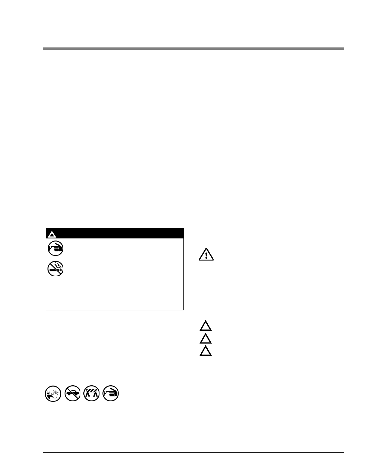
Safety Symbols and Warning Words
This section provides important information about warning
symbols and boxes.
Alert Symbol
This safety alert symbol is used in this manual and on
warning labels to alert you to a precaution which must be
followed to prevent potential personal safety hazards. Obey
safety directives that follow this symbol to avoid possib le inj ury
or death.
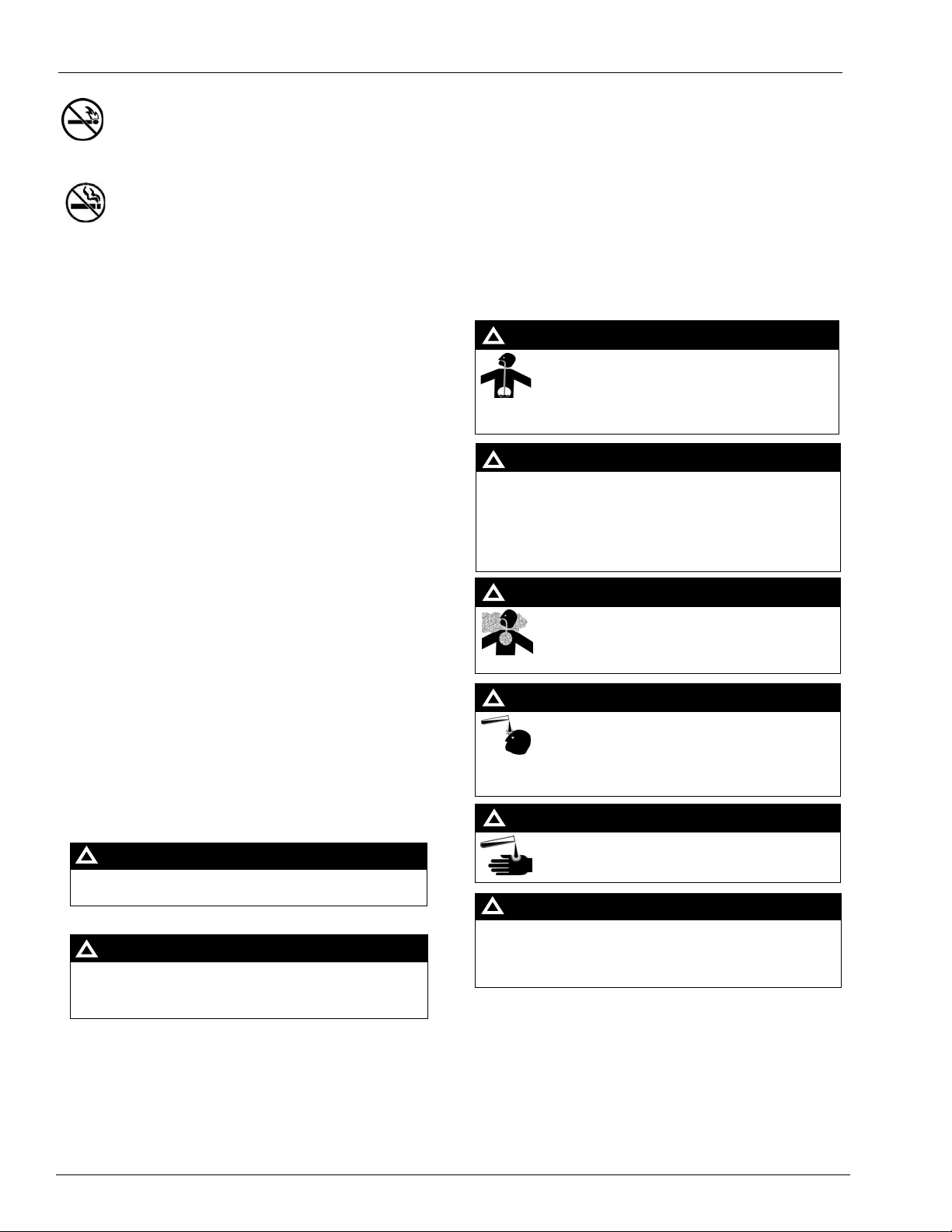
Signal Words
These signal words used in this manual and on warning labels
tell you the seriousness of particular safety hazards. The
precautions below must be followed to prevent death, injury or
damage to the equipment:
DANGER: Alerts you to a hazard or unsafe practice
!
which will result in death or serious injury.
WARNING: Alerts you to a hazard or unsafe practice
!
that could result in death or serious injury.
CAUTION with Alert symbol: Designates a hazard or
!
unsafe practice which may result in minor injury.
CAUTION without Alert symbol: Design ates a hazard or
unsafe practice which may result in property or
equipment damage.
Working With Fuels and Electrical Energy
• An evacuation of all unauthorized persons and vehicles from
the work area
• Use of safety tape, cones or barric ades at the affected unit(s)
• A total electrical shut-off of the affected unit(s)
MDE-4333E Atlas Fuel Systems Site Preparation Manual · November 2011 Page 5
Prevent Explosions and Fires
Fuels and their vapors will explode or burn, if ignited. Spilled or
leaking fuels cause vapors. Even filling customer tanks will
cause potentially dangerous vapors in the vicinity of the
dispenser or island.
DEF is non-flammable. Therefore, explosion and fire safety
warnings do not apply to DEF fluid lines.
Page 10
Important Safety Information
No Open Fire
In an Emergency
Inform Emergency Personnel
Compile the following information and inform emergency
Open flames from matches, lighters, welding torches or
other sources can ignite fuels and their vapors.
No Sparks - No Smoking
personnel:
• Location of accident (for example, address, front/back of
building, and so on)
• Nature of accident (for example, possible heart attack, run
over by car, burn s, and so on)
Sparks from st arting vehicles, starting or using power tools,
burning cigarettes, cigars or pipes can also ignite fuels and their
vapors. Static electricity, including an electrostatic charge on
your body, can cause a spark sufficient to ignite fuel vapors.
Every time you get out of a vehicle, touch the metal of your
• Age of victim (for example, baby, teenager, middle-age,
elderly)
• Whether or not victim has received first aid (for example,
stopped bleeding by pressure, and so on)
• Whether or not a victim has vomited (for example, if
swallowed or inhaled something, and so on)
vehicle, to discharge any electrostatic charge before you
WARNING
approach the dispenser island.
!
Gasoline/DEF ingested may cause
Working Alone
It is highly recommended that someone who is capable of
rendering first aid be present during servicing. Familiarize
yourself with Cardiopulmonary Resuscitation (CPR) methods, if
unconsciousness and burns to internal organs.
Do not induce vomiting. Keep airway open.
Oxygen may be needed at scene. Seek medical
advice immediately.
you work with or around high voltages. This information is
available from the American Red Cross . Alw ay s advise the
station personnel about where you will be working, and caution
them not to activate power while you are working on the
equipment. Use the OSHA Lockout/Tagout procedures. If you
are not familiar with this requirement, refer to this information in
the service manual and OSHA documentation.
Working With Electricity Safely
Ensure that you use safe and established practices in working
with electrical devices. Poorly wired devices may cause a fire,
explosion or electrical shock. Ensure that grounding
connections are properly made. Take care that sealing devices
and compounds are in place. Ensure that you do not pinch wires
when replacing covers. Follow OSHA Lockout/Tagout
requirements. Station employees and service contractors need
to understand and comply with this program completely to
ensure safety while the equipment is down.
WARNING
!
DEF generates ammonia gas at higher temperatures.
When opening enclosed panels, allow the unit to air out to
avoid breathing vapors.
If respiratory difficulties develop, move victim a way from
source of exposure and into fresh air. If symptoms persist,
seek medical attention.
WARNING
!
Gasoline inhaled may cause unconsciousness
and burns to lips, mouth and lungs.
Keep airway open.
Seek medical advice immediately.
WARNING
!
Gasoline/DEF spilled in eyes may cause burns to
eye tissue.
Hazardous Materials
Some materials present inside electronic enclosures may
present a health hazard if not handled correctly . Ensure that you
Irrigate eyes with water for approximately
15 minutes.
Seek medical advice immediately.
clean hands after handling equipment. Do not place any
WARNING
equipment in the mouth.
!
Gasoline/DEF spilled on skin may cause burns.
!
WARNING
The pump/dispenser contains a chemical known to the
State of California to cause cancer.
WARNING
!
The pump/dispenser contains a chemical known to the
State of California to cause birth defects or other
reproductive harm.
!
DEF is mildly corrosive. Avoid cont act with eyes , skin, and
clothing. Ensure that eyewash stations and safety
showers are close to the work location. Seek medical
advice/recommended treatment if DEF spills into eyes.
IMPORTANT: Oxygen may be needed at scene if gasoline has
been ingested or inhaled. Seek medical advice immediately.
Lockout/Tagout
Wash area thoroughly with clear water.
Seek medical advice immediately.
WARNING
Lockout/Tagout covers servicing and maintenance of machines
and equipment in which the unexpected energization or st art-up
of the machine(s) or equipment or release of stored energy
could cause injury to employees or personnel. Lockout/Tagout
applies to all mechanical, hydraulic, chemical, or other energy,
but does not cover electrical hazards. Subpart S of 29 CFR Part
1910 - Electrical Hazards, 29 CFR Part 1910.333 contains
specific Lockout/Tagout provision for electrical hazards.
Page 6 MDE-4333E Atlas Fuel Systems Site Preparation Manual · November 2011
Page 11
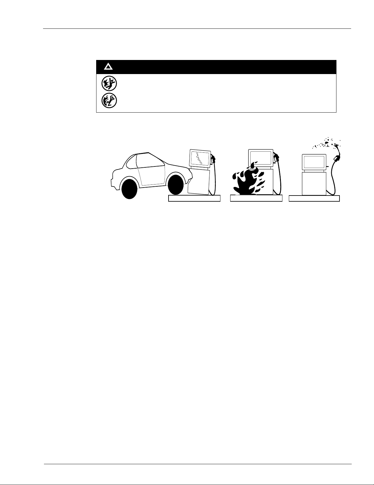
Hazards and Actions
!
The following actions are recommended regarding these hazards:
Important Safety Information
WARNING
Spilled fuels, accidents involving pumps/dispensers, or uncontrolled fuel flow create a
serious hazard.
Fire or explosion may result, causing serious injury or death.
Follow established emergency procedures.
DEF is non-flammable. However it can create a slip hazard. Clean up spills promptly.
Collision of a Vehicle with Unit Fire at Island Fuel Spill
• Do not go near a fuel spill or allow anyone else in the area.
• Use station EMERGENCY CUTOFF immediately. T urn of f all system circuit brea kers to the island(s).
• Do not use console E-STOP, ALL STOP, and PUMP STOP to shut off power. These keys do not
remove AC power and do not always stop product flow.
• Take precautions to avoid igniting fuel. Do not allow starting of vehicles in the area. Do not allow
open flames, smoking or power tools in the area.
• Do not expose yourself to hazardous conditions such as fire, spilled fuel or exposed wiring.
• Call emergency numbers.
MDE-4333E Atlas Fuel Systems Site Preparation Manual · November 2011 Page 7
Page 12

Important Safety Information
This page is intentionally left blank.
Page 8 MDE-4333E Atlas Fuel Systems Site Preparation Manual · November 2011
Page 13

Station Layout Site Preparation
3 – Site Preparation
IMPORTANT INFORMATION
When preparing the site, use safety tape, cones, or barricades to block the work area.
Station Layout
Recommended guidelines for the Station Layout are as follows:
• Consider traffic flow, kiosk, and store location when planning location of pumps/dispensers.
• Plan islands for efficient routing of plumbing and wiring. Arrange product lines by hose
and foundation layouts (refer to MDE-4331 Atlas Fuel Systems Installation Manual).
Follow local codes.
Note: Actual flow rates will depend on your specific installation and accessories used.
Remember pipe size and number of fittings can affect flow rate. Refer to
Considerations for DEF Dispensers” on page 26.
• Place pumps/dispensers such that the customers can dispense fuel safely and conveniently.
• Install pumps/dispensers at least 8-feet apart on island.
• Consider the service person who must have easy access to the entire pump/dispenser (top,
rear, front, and sides). Gasboy recommends at least 60 inches of clearance from any
structure (for example, wall, fence).
• Install protective posts at ends of island to protect pumps/dispensers against collision.
Posts must not interfere with customer fueling.
“Important
Product System Layout
• Distance from tank to pump must not be more than 50-feet.
• Fuel line dimensions, refer to “Pipe Size” on page 30.
• Fuel line minimum burial depth starting at inlet riser to the pumping unit is 18 inches.
• Fuel line piping sloping rate of 1-1/2 to 2 inches per 10-feet of piping run.
Note: Traps and sags are not acceptable.
• Avoid unnecessary elbows and/or turns in piping. Each elbow and turn decreases product
flow and if used in excess may cause issues with fuel delivery.
• Maximum lift is 10-feet (refer to “Fuel Tanks” on page 29).
• Pumps (self contained units) must have a vacuum actuated pressure regulating valve to
prevent positive pressure at the pump base when used with aboveground tanks.
• For aboveground tank installations, refer to “Shear Valves” on page 31 and
“Pipe Installation” on page 29.
MDE-4333E Atlas Fuel Systems Site Preparation Manual · November 2011 Page 9
Page 14

Site Preparation Station Security
Station Security
This section includes information that is primarily applicable to Commercial sites and some
Retail sites. It may be impossible with any manufacturer’s unit even if it is designed for
security, to stop a knowledgeable, unobserved experienced thief. It is possible to greatly
reduce the probability that a theft will be successfully attempted, if security measures are
designed into the station layout and security minded actions are planned into site operation.
Steps to Enhance Security
The following recommendations are intended to decrease the probability of theft by
observance and/or incorporating obstacles that deter criminal activity:
• Design stations where employees have full unobstructed view of all fueling locations. Do
not block employee views with merchandise displays or other obstructions. If full view is
not possible, utilize video surveillance equipment. Monitoring of equipment must be made
obvious and signs stating its use must be posted.
• Use pump/dispenser security kits, when available.
• For Fuel management or console models with “time out” programming capabilities, plan
to use modular programming “time out” functions that shut down the unit if no pulser
activity occurs for a preselected time.
• Plan to provide periodic/frequent inspection of equipment security provision s to verify
their integrity.
• For electronic retail units, enter a new programming access code, as default codes are
commonly known. These codes must only be known by trusted station employees and the
involved ASCs.
• At installation and all times thereafter, ensure that lower door locks are adjusted correctly
and will not allow the panels to be removed easily without a key or tool. If you suspect
that keys are available to thieves in your area, consider using special locks or keys
available from locksmiths.
• Use surveillance cameras especially for high risk locations and locations potentially
blocked from view .
• Observe POS warnings or messages for units offline, when available.
Page 10 MDE-4333E Atlas Fuel Systems Site Preparation Manual · November 2011
Page 15

Equipment and Materials Required at Site Site Preparation
Equipment and Materials Required at Site
WARNING
Use of incompatible materials or components with alternative fuels such as E85 can result
in leaks or unexpected failures of components resulting in fire, explosion, or environmental
damage.
When dispensing alternative fuels such as E85, verify with the manufacturer if the material
of all plumping components are compatible with fuels such as E85 being dispensed.
• Fuel storage tanks
• STPs and leak detectors for dispensers
• Piping and fittings
• Pit boxes (also known as dispenser sumps)
• Shear valves for dispensers
• Check valves for pumps
• Conduit and gas/oil resistant wiring
• STP control relay boxes for dispensers
• Circuit breakers
• Isolation relays for electronic dispensers
• Emergency power cutoff switch
• Safety warning signs
Place warning signs (for example, No Smoking, Turn Off Engine) where fuel customers
will notice and read them. For warning signs, contact your local distributor.
• Conduit Seal (Potting) Compound (as required by seal manufacturer)
• For aboveground tanks with self-contained pumps, use vacuum-actuated
pressure-regulating valve with a shear section at the pump (Gasboy 52 valve)
• Distribution box(es) or service module(s) is required per unit type
• UL-approved sealant suitable for the application involved
• Wiring and conduit materials as outlined in the wiring diagram suitable for the fluid and
application involved
CAUTION
Applicable to Dispensers Rated for E85 Use:
Do not use tape at the very end of the pipe nipple to avoid tape entering the
dispenser hydraulics. Tape in the hydraulics can cause failures of valves, nozzles,
or other significant problems.
Use only UL-listed TPS PTFE Pipe Sealant manufactured by SAF-T-LOC
International Corp.
CAUTION
®
Use only UL-listed Taega Technologies Inc. Teflon
Note: Teflon tape must be used only at the inlet pipe connection.
MDE-4333E Atlas Fuel Systems Site Preparation Manual · November 2011 Page 11
tape.
Page 16

Site Preparation Electrical Requirements
Electrical Requirements
• DEF is non-flammable and creates no explosive vapors. Therefore, installation
requirements for DEF units differ from units that handle hazardous fuels. However,
electrical safety requirements are applicable. If a DEF unit is installed in the Class 1
Division 2 hazard zone of a pump/dispenser delivering flammable fluids, consult Gasboy
Technical Support to determine requirements for installing DEF units in that area.
Generally, the unit must be installed to comply with requirements for units handling
flammable fluids for the area within the hazard zone.
• Prepare sites according to NFPA 30A, NFPA 70, and applicable national, state, and local
codes/regulations.
• Use licensed electricians to make all electrical connections.
• Use a dedicated circuit/phase system. Wire all electronic units to the same power leg.
• Use an earth ground for circuits.
• Mount all circuit breaker panels and relay boxes securely to the wall.
• Use UL recognized/approved components and/or systems.
• Recommended voltages for pumping unit motors are 220VAC- single phase or
380VAC-3 phase.
• Route product wiring to protect from damage using conduit, as required.
Notes: 1) Pumping units require higher load levels than dispensers. For details, refer to
FE-356 Atlas Retail/Commercial Dispenser Field Wiring, FE-357 Atlas Pump
Retail/Commercial Field Wiring, and FE-361 Atlas Master & Satellite Field Wiring
Diagram.
2) Switched Neutral is not allowed in Canada.
Emergency Power Cutoff Switch
WARNING
Spills and collisions expose highly flammable and explosive fuels. Failure to install and use
an Emergency Power Cutoff could result in severe injury or death. Observe all safety
precautions in this and other manuals.
IMPORTANT INFORMATION
Devices such as D-Boxes, Two-wire, and so on must be de-energized or have wiring
disconnected from the dispenser by the Emergency Stop or equivalent mechanism.
Third-party devices such as those supplying power to any form of communication to a
dispenser (intercoms, RS-485 communications, third-party controllers and such) must
also be de-energized or the wiring supplying that power be disconnected. Provisio n to
accommodate this must not introduce noise (RFI or electrical) into sensitive pump
dispenser electronic field wiring circuits during normal pump/dispenser operation.
De-energizing of the external equipment through the Emergency Stop or equivalent
device is recommended.
• NFPA 30A and Gasboy require that you install one or more emergency power
cutoff switches.
• An emergency power cutoff switch is a sing le control that removes AC power to all island
equipment (pumps/dispensers, STPs, canopies, lights, and so on).
Page 12 MDE-4333E Atlas Fuel Systems Site Preparation Manual · November 2011
Page 17

Electrical Requirements Site Preparation
• Make the emergency power cutoff switch accessible, label it clearly, and install it away
from any hazard that may occur at the pumps/dispensers. Do not install cutoff switches
more than 100-feet away from the pumps/dispensers.
• Show all employees where the emergency power cutoff switch is located and how to use
it. Remind them often.
Notes: 1) Do not use E-STOP, ALL-STOP, or PUMP STOP keys on Gasboy console/cash
registers to shut-off pump/dispenser power. These keys do not remove AC power and
do not always stop product flow.
2) Daisy Chain Wiring is used to reduce wiring cost. However, it is not recommended
as it results in loss of power to all pumps in the event of one bad wire or bad
connection. Wiring shown in this manual is for non-daisy chain applications.
Units with Ground Fault Interrupt (GFI)
GFI Breakers are required for DEF dispensers mounted on Skid Tanks because of no
underground piping, AC power in potentially wet area, and a potential for earth ground to
break if Skid Tank moves.
A GFI consists of a sensor that detects changes in the current to the load, by comparing the
current flowing to the load and the current flowing from the load. A drop-off in the current
equivalent to about 5 milliamperes, turns off all power by tripping a relay within the GFI
within a few hundredths of a second.
When powering a dispenser with a GFI, the return neutral of any device to which the dispenser
supplies power must be the same neutral as that of the dispenser. For example, the STP control
relay.
MDE-4333E Atlas Fuel Systems Site Preparation Manual · November 2011 Page 13
Page 18

Site Preparation Electrical Requirements
Circuit Breakers
Figure 3-1: Circuit Breakers
Do not Use Use
• Install a dedicated UL/ULC/CSA-listed switched-neutral breaker to each circuit leading to
a pump/dispenser or dispenser and STPs. It must be able to disconnect hot and neutral
conductors simultaneously. Single-pole breakers with handle ties must not be permitted.
Ref. NEC 514.11 (Switched Neutral is not allowed in Canada).
• Use only UL/ULC/CSA-listed circuit breaker panel as appropriate for that area.
• Install circuit breakers away from the pumps/dispensers. They must be readily accessible
and clearly marked.
• Install a separate circuit breaker for each STP (dispenser models) or each pump motor
(self-contained models).
• Install one circuit breaker for each pump/dispenser or small island group to allow
powering down of pump/dispenser for service.
Power to the unit must be supplied from a dedicated breaker.
• No other equipment must be powered from this breaker.
• Remote dispensers may be grouped together on a single breaker when the submersible
pump has its own breaker.
• It is recommended that no more than two remote dispensers be powered from one breaker
to maintain isolated control with the circuit breaker panel in case of problems.
• Units directly driving pumps (suction or submersible) must be supplied power from a
separate breaker. A tag on the motor identifies the maximum current draw of the motor. If
two pumps are supplied from one breaker, that breaker must be capable of handling the
load of both motors.
• DEF units contain a special heater to prevent the DEF fluid from freezing during very cold
weather. Properly size circuit breakers to handle normal pump/dispenser power
requirement plus that for the heater.
CAUTION
In cases where multiple remote dispensers supply power to a single submersible
pump, all breakers controlling the remote dispenser must be on the same phase of
power. Failure to do this will damage the equipment. Provisions must be made to
break both legs of any AC circuit.
STP Control Relay Boxes for Dispensers
• Install a separate control relay for each STP.
• Do not use the dispenser relay to power the STP.
• Combined STP Control Relay/Isolation Relay boxes are recommended.
Page 14 MDE-4333E Atlas Fuel Systems Site Preparation Manual · November 2011
Page 19

Electrical Requirements Site Preparation
STP Isolation Relays for Electronic Dispensers
STP isolation relays provide electrical isolation between dispensers and prevent damage from
Conduit
cross phasing. Refer to MDE-4334 Atlas Start-up/Service Manual and FE-356 Atlas
Retail/Commercial Dispenser Field Wiring.
Note: For 3-phase STP, use isolation relay at the input of the 3-phase STP control box.
• Gasboy requires installation of STP isolation relays in addition to STP control relays.
• Use isolation relays for each STP control line at each dispenser or dispenser grouping on a
single circuit breaker.
• Route neutral wire to the control relays from the dispenser circuit breaker (refer to FE-356
Atlas Retail/Commercial Dispenser Field Wiring, FE-357 Atlas Pump Retail/Commercial
Field Wiring, and FE-361 Atlas Master & Satellite Field Wiring Diagram).
• Combined STP Control Relay/Isolation Relay boxes are recommended.
• DEF is non-flammable and creates no explosive vapors. Therefore, installation
requirements for DEF units differ from units that handle hazardous fuels. However,
electrical safety requirements are applicable. If a DEF unit is installed in the Class 1
Division 2 hazard zone of a pump/dispenser delivering flammable fluids, consult Gasboy
Technical Support to determine requirements for installing DEF units in that area.
Generally the unit must be installed to comply with requirements for units handling
flammable fluids for the area within the hazard zone.
• Use 1-inch trade size rigid aluminum conduit with Gasboy pumps/dispensers to connect
wires to the pump/dispenser (Retail).
Two-wire data wires for retail electronics can share power wiring conduit (refer to
model-specific wiring diagrams).
Four-wire data wires for RS-485 communications can share power wiring conduit (refer to
model-specific wiring diagrams).
• Use a threaded, rigid metal conduit or a rigid non-metallic conduit for applications below
the pump/dispenser to carry electrical wires. Conduit must conform to national and local
electrical codes. If you use a nonmetallic conduit, it must be at least 2-feet underground.
The last 2-feet of the underground run to the junction box must be rigid metal conduit or
threaded steel intermediate metal conduit. Tighten all threaded conduits.
• Never share conduit or wire troughs with other manufacturers’ equipment (for example,
speaker wires, canopy lights, and so on). When using RS-485 communications with Atlas
Commercial units communicating with TopKAT
be in separate conduit. For more details, refer to
Note: You can use the same conduit for routing power to the pump/dispenser and the
Two-wire (Retail) data loop (Class 1 circuit). The Two-wire data loop is a Class 1
circuit.
• Never rely on metal conduit to provide an equipment ground. Run a separate ground wire.
• Never use knock-out boxes or flexible conduit for installation.
Note: Extra junction boxes added to the pump/dispenser must be listed Class 1, Div. 1,
Group C and D explosion-proof.
• Use electrical fittings that are listed for Class 1, Group C and D hazardous locations, as
required by NFPA 30A and NFPA 70.
™
or CFN®, all AC and DC wiring must
“Atlas - Commercial” on page 16.
MDE-4333E Atlas Fuel Systems Site Preparation Manual · November 2011 Page 15
Page 20

Site Preparation Electrical Requirements
• A seal-off ‘Y’ fitting (for example, Killark® Type EY) must be installed on all units as a
first connection where conduit leaves the ground.
• If TopKAT is factory mounted, a separate conduit must be installed. Refer to the TopKAT
documentation for field wiring.
— MDE-4319 TopKAT Fuel Management System Installation Manual
— MDE-4331 Atlas Fuel Systems Installation Manual
Wiring
The distinction between the Commercial and Retail pump/dispenser units is that the
Commercial unit must use the separate conduit arrangement to keep the signals from
interfering with one another or other noise generating devices, whereas with the Retail unit
this is not required.
Atlas - Commercial
The Atlas Commercial pump/dispenser utilizes two conduits, one for AC power and second
for the DC signals (the two conduits must be kept separate to reduce signal interference). The
AC conduit carries AC power line and supplies power to the valves and motors, whereas the
DC conduit delivers the RS-485 signal when used with a CFN and TopKAT, or Pulse Output
when used with a series 1000 or other manufacturer’s control system.
When installed in a separate DC conduit, 18 American Wire Gauge (AWG) wires are required
for installation. Although it is recommended that DC Commercial pump interface wires
(RS-485 or Pulse Output) be run in a conduit separate from AC wires, they can be combined in
the same conduit with AC wires provided UL-listed cable with the following specifications are
used.
Components/Parameters Specification
Conductor 18 AWG stranded wire. Number of conductors to be determined by pulser
requirements (to determine number of wires used, refer to wiring diagram ).
Shield Foil-wrapped 100% coverage and/or tinned copper braid 90% coverage.
Drain Wire Stranded, tinned copper, 20 AWG, or larger/or braided shield.
Voltage Rating Maximum operating voltage of 600 V.
Environmental Gas and oil-resistant, suitable for wet or dry locations.
Gasboy can supply Belden
that meets the requirements listed above.
Note: Belden 1063A is UL-listed but not CSA-listed.
Atlas - Retail
The Atlas Retail pump/dispenser utilizes only one main conduit as it does not require a DC
conduit. The AC conduit is used to carry AC wire and Two-wire, twisted-pair wiring.
®
1063A (P/N C09655) which is a UL-listed, four-conductor cable
Page 16 MDE-4333E Atlas Fuel Systems Site Preparation Manual · November 2011
Page 21

Electrical Requirements Site Preparation
Wiring Requirements
• Wire all pumps/dispensers according to NFPA 30A, NFPA 70, and applicable national,
state, and local codes/regulations.
• Wire all circuits N.E.C Class 1.
• Use stranded gas and oil resistant copper wire rated for 300 V (up to 240VAC source) and
80 °C.
• In the main conduit of Retail units, for communications, use only twisted-pair, Two-wire
data pairs. Do not use shielded twisted-pair wiring.
• Unshielded twisted-pair wire is required per the following:
— Retail Two-wire communication wiring for new installations.
— Replacement units, depending on location of the wiring conduit and previous unit st yle,
may require new wiring or adaptive conduit, explosion proof junction box, and jumper
wiring to mate with the old wiring.
— Previously wired stations may continue to use tested existing non-twisted-pair wiring
that has been short and continuity tested and passed, where communication problems
between the older units and console have not been a problem. Twisted-pair wiring is
highly recommended for existing stations experiencing higher than national average
lightning strikes or for stations previously experiencing console to dispenser
communication problems.
• Leave 3-feet of wire out of conduit for connection to dispenser.
• Place dispensers on the same phase.
Note: If Gasboy isolation relay box is installed, dispensers are not required to be on the
same phase.
• Use listed wire nuts for all connections. Do not use tape.
• Pull spare wires for future use.
• Protect conduit ends and wire from water or damage prior to installation of the
pumps/dispensers.
• Seal-off ‘Y’ fitting(s) must be potted after all wires are run to termination points.
For additional wiring notes and requirements, refer to the following documents:
• FE-356 Atlas Retail/Commercial Dispenser Field Wiring
• FE-357 Atlas Pump Retail/Commercial Field Wiring
• FE-361 Atlas Master & Satellite Field Wiring Diagram
Retail Data Wire Lengths
Use the following table to determine maximum Retail data wire lengths.
For This Distribution Box
PA0133, PA0187 G-SITE
PA0242 Transac® System 1000™
PA0261 Universal D-Box
PA0306 Distribution Box
Distance Between the Distribution
Distance Between the Distribution
Box and Dispenser
®
“Total” data wire system run no more than 2600-feet with 14 AWG
No more than 2600-feet with 14AWG No more than 2600-feet with 14AWG
Box and
Console/Controller
MDE-4333E Atlas Fuel Systems Site Preparation Manual · November 2011 Page 17
Page 22

Site Preparation Electrical Requirements
Commercial Data Wire Lengths
Use the following table to determine maximum Commercial data wire lengths.
Distance Between the Distribution
Distance Between the Distribution
For this Distribution Box
RS-485 Cable No more than 1000-feet from junction
Box and Dispenser
box to farthest CFN or TopKAT
component
Box and
Console/Controller
No more than 1500-feet between all
CFN or TopKAT components
Grounding
GFI Breakers are required for DEF dispensers mounted on Skid Tanks because of no
underground piping, AC power in potentially wet area, and a potential for earth ground to
become broken if Skid Tank moves.
A GFI consists of a sensor that detects changes in the current to the load, by comparing the
current flowing to the load and the current flowing from the load. A drop-off in the current
equivalent to about 5 milliamperes, turns off all power by tripping a relay within the GFI
within a few hundredths of a second.
When powering a dispenser with a GFI, the return neutral of any device to which the dispenser
supplies power must be the same neutral as that of the dispenser. For example, the STP control
relay.
• NFPA 70 requires that you connect the following to system ground:
— Consoles
— Pumps and dispensers
— Submerged turbine pumps
— Relay control boxes
— Circuit breaker panel
— Electronic leak detectors
— Service module
— Distribution box
• Gasboy requires that you connect each pump/dispense r to an equipment grounding
conductor located in the conduit per NFPA 70, Article 250. The fol lowing is applicable to
ground conductor:
— Gasboy recommends using wire no smaller than 12 AWG. A larger wire may be
required per NFPA 70, Article 250.
— Use wire with green, or green and yellow striped insulation.
— Connect to grounding screw in junction box.
— Ground the providing power under NFPA 70, Article 250.
— Bond the neutral bus to an approved grounding electrode.
To ensure proper operation of the equipment and provide the required safety factors, this unit
must be grounded per the following:
• A ground wire (preferably green) must be connected between the unit’s AC junction box
ground lug and the main electrical service panel.
• One earth ground connection is required per unit.
• The ground rod must be a solid, corrosion-resistant conductor, and must be installed at the
main electrical panel in accordance with the National Electrical Code. It must be properly
tied into the ground bus strip of the panel.
• W e recommend the neutral and ground bus strips be bonded together (unless prohibited b y
local codes).
Page 18 MDE-4333E Atlas Fuel Systems Site Preparation Manual · November 2011
Page 23

Electrical Requirements Site Preparation
Figure 3-2: Grounding Plan
Refer to “Conduit”
on page 15 .
MDE-4333E Atlas Fuel Systems Site Preparation Manual · November 2011 Page 19
Page 24

Site Preparation Electrical Requirements
Electrical Control Lines
This section provides control input and output information for the Atlas pump/dispensing unit.
For electrical wiring information, refer to the following:
• FE-356 Atlas Retail/Commercial Dispenser Field Wiring
• FE-357 Atlas Pump Retail/Commercial Field Wiring
• FE-361 Atlas Master & Satellite Field Wiring Diagram
Light Feed
The light feed is a 115 VAC (230 VAC International) input required to power the fluorescent
lights. In a site configuration using multiple remote dispensers (or pumps), the power for the
lights of upto eight units can be supplied by one breaker . If separ ate control of the lights is not
required, the light feed for each dispensing unit may be taken from its Reset Motor Feed.
Light Neutral
The light neutral is a return line for AC from the lights to the breaker panel. When a separate
breaker is not used to control the lights, the light neutral is attached to the neutral which is
connected to the reset motor.
Phase 2 Feed
The phase 2 feed is a hot feed which is the opposite phase of the pump motor feed. This line
and pump motor feed are used for domestic 230 VAC motor applications.
Pulse Out (Commercial Only)
The Pump Interface Boards (Pulse Out and RS-485) supplies a DC output which is provided to
indicate the quantity dispensed. Pump Interface Boards are optional and are only used when
monitoring of the dispensing unit operation is required as when used with a fuel management
system.
Note: Customers and installers having any questions pertaining to the installation must
contact their Gasboy distributor.
Page 20 MDE-4333E Atlas Fuel Systems Site Preparation Manual · November 2011
Page 25

Electrical Requirements Site Preparation
Wiring Overview
The quality of the electrical installation is a major factor in maintaining proper safety levels
and providing trouble-free operation of your Gasboy pump/remote dispenser (refer to
“Electrical Requirements” on page 12). To assure a quality installation, follow these rules:
1 All wiring must be installed to conform with all building/fire codes, all Federal, State, and
Local codes, National Electrical Code, NFPA 70, NFPA 30, and Automotive and Marine
Service Station Code (NFPA 30A) codes and regulations. Canadian users must also comply
with the Canadian Electrical Code.
2 Use only threaded, rigid, metal conduit. For more details, refer to “Conduit” on page 15.
3 Use only UL-labeled, insulated, gasoline and oil-resistant stranded copper wiring of the proper
size (refer to
4 Wire connections must be tightly spliced and secured with a wire-nut. Close off the open end
of the wire nut with electrical tape.
“Atlas - Commercial” on page 16).
5 The line to the motor must be on a separate circuit and installed on a 20 to 30 A breaker
depending on the motor size and/or the voltage setting (refer to
page 14).
“Circuit Breakers” on
6 Install an emergency power cutoff (refer to “Emergency Power Cutof f Switch” on page 12). In
addition to circuit breaker requirements of NFPA 70 and NFPA 30A, a single control which
simultaneously removes AC power from all site dispensing equipment is recommended. This
control must be readily accessible from all fueling positions, clearly labeled, and in
accordance with all local codes.
In a fuel management system application, the EMERGENCY STOP and STOP keys on the
console and/or the optional EMERGENCY STOP button on the Island Card Reader do not
remove AC power from equipment, and under certain conditions, will not stop product flow.
7 To provide the highest level of safety to you, your employees, and customers, all employees
must be trained as per the location and procedure for turning off power to the entire system.
WARNING
To reduce the risk of electrical shock when servicing, turn off all power to the pump/remote
dispenser. In submersible pump applications, turn off power to the submersible pump and
any other remote dispensers which use that submersible pump. AC power can feed back
into a shut-off dispenser when dispensers share a common submersible pump or starter
relay.
8 The distinction between the Commercial and Retail pump/dispenser units is that the
Commercial unit must use the separate conduit arrangement to keep the signals from
interfering with one another or other noise generating devices whereas with the Retail unit this
is not required.
9 Ensure that the pump/remote dispenser is installed by a competent installer/electrician.
MDE-4333E Atlas Fuel Systems Site Preparation Manual · November 2011 Page 21
Page 26

Site Preparation Electrical Requirements
Pump Motors
Pumps are shipped from the factory with motors wired according to the specifications given
on the order as to kind of current, frequency, and voltage.
Very often on installation, it becomes necessary to change the original setting to suit the AC
power source. T o do this, locate the motor change-over plate, typically located on the shaft end
of the motor and remove the screw which secures it in place. Slide the plate so that the
required voltage as marked on the plate, lines up with the screw hole. Reinsert the screw and
secure the plate in place.
Many motor failures result from improper setting of the motor change-over plate. If set for
115 VAC and 230 VAC feed is used, the motor will burn out after running only a short ti me. If
set for 230 VAC and 115 VAC feed is used, the motor will run very slowly and the starting
field will soon burn out.
Motor Loads
The following table shows the maximum running amperage that can be expected for the pump
motor, unless noted otherwise.
Model
9152K, 9152KTW1, 9152KTW2
9852K, 9852KTW1, 9852KTW2
8152K, 8152KTW1, 8152KTW2
8852K, 8852KTW1, 8852KTW2
9153K, 9153KTW2
9853K, 9853KTW2
8153K, 8153KTW2
8853K, 8853KTW2
9140K
9840K
9850K N/A 10.0 A N/A N/A
9872KX, 9872KXTW1 N/A N/A N/A N/A
Notes: 1) Inadequate feed wiring (too long or too small a diameter wire) will incr ease current
draws on the motor and/or reduce voltage at the motor. This may also reduce motor
life.
2) These numbers do not account for the higher load upon start-up, nor up to one
additional Amp associated with other electrical components (lights, solenoid valves,
and so on).
3) All model numbers ending in TWIM or TW2 have one pump motor per side. 9140K
and 9840K also have one pump motor per side.
4) The 9140K and 9840K models must use no less than a 20 A breaker to account for
the high current upon start-up.
115 V 50/60 HZ
1 PH
13 A 6.5 A 3.4 A 2.3 A
13.0 A per motor 6.5 A per motor 3.4 A per motor 2.3 A per motor
Motor Rating
230 V 50/60 HZ
1 PH
230 V 50/60 HZ
3 PH
380 V 50/60 HZ
3 PH
Page 22 MDE-4333E Atlas Fuel Systems Site Preparation Manual · November 2011
Page 27

Electrical Requirements Site Preparation
Heater Load Table
Load Table Reference Locations - DEF Dispensers (Cold Weather Units Only)
A separate breaker is required for the heater (8.5 A @ 120 VAC 60 Hz). For more information,
refer to FE-356 Atlas Retail/Commercial Dispenser Field Wiring.
Note: Heaters are thermostatically controlled and will cycle between on and off during cold
weather to maintain a minimum cabinet temperatur e.
Sealing ‘Y’ Fittings
‘Y’ seals are installed in conduit runs to minimize passage of vapors, gases, or flames from
one portion of the electrical installation to another through the conduit. Fittings must be
installed in accordance with Articles 501-5 and 502-5 of the National Electric Code and fitting
manufacturers’ instructions.
DEF is non-flammable and creates no explosive vapors. Therefore, installation requirements
for DEF units differ from units that handle hazardous fuels. However, electrical safety
requirements are applicable. If a DEF unit is installed in the Class 1 Division 2 hazard zone of
a pump/dispenser delivering flammable fluids, consult Gasboy Technical Support to determine
requirements for installing DEF units in that area. Generally the unit must be installed to
comply with requirements for units handling flammable fluids for the area within the hazard
zone.
Gasboy uses Killark
conduit runs. The following sealing directions are for Killark fittings only and instructions
may vary for other manufacturer’s fittings. Read through all instructions completely before
beginning.
Figure 3-3: Sealing ‘Y’ Fittings
Conduit
Type EY fittings and recommends them or their equivalent for vertical
Wires
Close-up plug
Fill to bottom of
threads
Floor dam
Conduit
MDE-4333E Atlas Fuel Systems Site Preparation Manual · November 2011 Page 23
Sealing compound
Page 28

Site Preparation Electrical Requirements
1 Remove the close-up plug.
2 Separate conductors and fill conduit in and around conductors using Killark type “PF” packing
fiber to make a floor dam to hold fluid sealing compound.
Note: Floor dam must be even with the conduit stop in the lower hub of fitting. Exercise care
so as not to damage conductor insulation. Force packing between conductors and hubs,
pushing any shreds of packing fiber away from conductors to prevent leakage path.
3 Use only Killark Type “SC” sealing compound with Killark fittings and do the following:
• Use a clean mixing vessel for every batch of sealant.
• Mix compound at the rate of 3 parts compound to 1 part water by volume.
• Sprinkle compound in water while stirring until thick paste is formed.
Note:Do not mix more compound than can be used in 15 minutes.
• Continue mixing for at least 3 minutes, until consistency is just fluid enough to pour
slowly, like thick gravy (not watery).
4 Slowly pour approved fluid compound into sealing fitting to level of bottom of threads for
close-up plug.
Note: Pour slowly to avoid trapping air bubbles in s eal.
5 Immediately wipe off any spilled compound and close seal with the close-up plug.
Note: Initial setting of sealing compound will occur within 30 minutes. Compound requires a
minimum of eight hours above 32 °F to develop sufficient strength to withstand
explosion pressures.
Page 24 MDE-4333E Atlas Fuel Systems Site Preparation Manual · November 2011
Page 29

Plumbing Requirements Site Preparation
Plumbing Requirements
WARNING
Highly flammable and explosive fuels are present. Failure to observe all safety precautions
could result in severe injury or death. Observe all safety precautions in this and other
manuals.
Connecting the Pump/Dispenser Inlet Pipes
WARNING
DEF, flexible fuels such as Biodiesel, high alcohol percentage fuels, and so on, may be
incompatible with certain plumbing materials and hydraulic components.
®
Use recommended sealant, Loctite
(Part Number 21347) for DEF pipe threads. Do not use thread tape.
#567 (Part Number 56747) and Loctite Primer-N 7649
Use only UL-listed TPS PTFE Pipe Sealant manufactured by SAF-T_LOC International Corp.
for E85 pipe connections.
Use of incompatible materials or components with alternative fuels such as E85 or DEF can
result in leaks or unexpected failures of components resulting in fire or explosion or
environmental damage.
When dispensing alternative fuels such as E85 or DEF, verify with the manufacturer of the
material or component that all plumbing components are compatible with the fuels or DEF
being dispensed. Do not replace the dispenser or pump parts with those incompatible with the
fuel or DEF involved.
WARNING
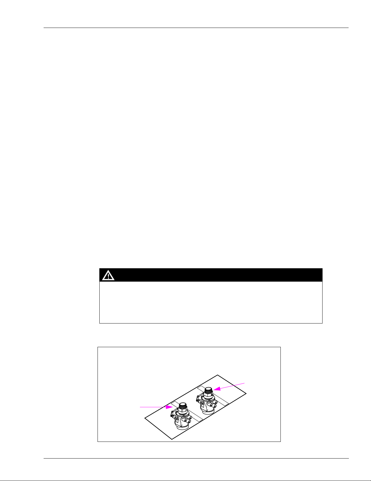
The Shear Valves must be installed correctly.
Improperly or insufficiently anchored Shear Valves can lead to fire or explosion that could
result in severe injury or death.
Anchor all the Shear Valves as per the manufacturer’s instructions.
MDE-4333E Atlas Fuel Systems Site Preparation Manual · November 2011 Page 25
Page 30

Site Preparation Plumbing Requirements
Important Considerations for DEF Dispensers
CAUTION
Applicable during Installation and Operation of the Dispenser: DEF freezes at approximate ly
11 °F (-11.5 °C). Power to the dispenser and heater must always remain ON in cold weather. If
power is lost and the temperature drops below this point, the system must be inspected for freeze
damage before restart. For sites that experience occasional power losses or for sites that are
located in very cold climates, it is recommended that a back up power generator be used to
maintain constant power to the dispenser. Do not use any additives to lower the freezing point of
DEF. Additives of any type must not be used in DEF.
Prolonged storage at temperatures above 77 °F (25 °C) can impair the quality of DEF and reduce
its shelf life.
CAUTION
DEF is mildly corrosive. It can corrode components that are made from incompatible material(s)
and reduce their integrity. The use of incompatible material(s) may lead to leaks and spills, and can
contaminate and degrade the DEF. When dispensing DEF, verify with the manufacturer if the
material of all plumbing components are compatible with the DEF being dispensed.
CAUTION
Do not use Prover Cans meant for engine fuel with DEF or vice versa. Use stainless steel Prover
Cans for DEF. DEF and engine fuel must not be mixed with each other or be contaminated by each
other. Else, damage to a vehicle’s engine or pollution control devices could occur. DEF crystallizes
as its water base evaporates. Pouring out liquid will not guarantee that no corrosive DEF remains in
the Prover Can. DEF must not be contaminated with Diesel fuel, contaminants, or other fluids or
materials. Such contamination can cause serious damage to vehicle catalytic converters.
• Conventional fluid handling precautions are also applicable to DEF.
• Avoid contact with eyes, skin, and clothing. Ensure that eyewash stations and safety
showers are close to the work location.
• DEF is mildly corrosive and non-flammable.
• Clean the DEF spill with water and dry the area with clean rags, especially areas that
contain metallic parts. Spilt DEF can be slippery and will corrode certain types of metallic
parts. Wear eye protection and rubber gloves during any cleanup activity.
Page 26 MDE-4333E Atlas Fuel Systems Site Preparation Manual · November 2011
Page 31

Plumbing Requirements Site Preparation
Important Considerations when Changing Fuel Types
WARNING
Certain special alternative fuels such as E85 and additives can degrade pump/dispenser
performance or integrity if the dispensers are not designed for use with such fu els.
Additionally, converting to certain standard fuels (gasoline, diesel, kerosene, and so on)
from alternative fuels such as those with ethanol (E85), methanol, or Biodiesel or from
alternative fuels to standard fuels can degrade dispenser performance or integrity. Similar
effects can also occur when converting units to different standard fuel types. As per UL
87A requirements, nozzles dispensing E85 fuel must not be used to dispense any
other type of fuel such as Gasoline.
Leaks and potential environmental hazards can result or components may fail prematurely.
To avoid these issues, follow the guidelines in this section.
Follow the guidelines given below when changing fuel types for a pump/dispenser or using
alternative fuels or fluids.
• Verify with your Gilbarco ASC or Distributor if the fuel which you will be using is
compatible with the pumps/dispensers to be dispensing the fuel.
• For flexible fuel dispensers, do not use standard hydraulic parts used in other Gilbarco
pumps/dispensers for service parts in these units. Standard dispenser parts may not be
compatible with fluids.
• Biodiesel fuels must be of ASTM standards for Biodiesel fuels. Mixes of diesel with
cooking oils, other plant or animal derived oils, and so on are not considered Biodiesel.
Use of such mixes may void warranty on the hydraulic components of the unit.
• Review the latest copy of the unit’s warranty statement regarding the use of fuel.
• Certain fuels (especially fuels enhanced with alcohol) when first used in tanks previously
containing a different fuel may clean out the tanks and force a large amount of
contaminant into the dispenser. Other than abnormally clogging filters, this large quantity
of contaminant may damage certain dispenser components. Do not run units without
filters at such times. It is normally required that tanks and lines be cleaned of all water,
sediment, and contaminant prior to such conversions to minimize potential
pump/dispenser downtime or damage. Damage to hydraulic components from
contamination when not using filters is not covered by Warranty. Consult your ASC or
Gilbarco Distributor for recommendations.
• Do not use any equipment that was formerly used to store or dispense any other fuel or
liquid with DEF. Dispensers designed for use with DEF must only be used with DEF.
• Do not use Prover Cans meant for engine fuel with DEF or vice versa.
• Although conversions from one fuel to an equivalent fuel (for example, from another
supplier) generally do not create issues, it is recommended that after making any fuel type
conversions (refer to the above warning), all units be visually inspected for leaks two days,
one week, and one month after fuel conversion. Have your ASC repair any leaks found.
This must also be performed for standard fuels when significant new additives are
incorporated.
IMPORTANT INFORMATION
The above guideline does not apply to Flexible fuel model dispensers.
MDE-4333E Atlas Fuel Systems Site Preparation Manual · November 2011 Page 27
Page 32

Site Preparation Plumbing Requirements
• Whenever non-equivalent fuel conversions are performed, it is recommended that all units
be checked for calibration within one month of fuel conversion.
• Some non-equivalent fuel conversions will necessitate the requirement to change the
pump/dispenser filter type previously used. Consult your ASC or Gilbarco Distributor for
any changes required.
• In Flexible fuel dispensers, Gilbarco recommends the use of 10 micron filters for
gasoline-based flexible fuels. Although the use of finer filtration is allowable, filters will
tend to clog prematurely, causing excessive filter maintenance cost.
• Use only meters and registration devices for DEF that have a National Type Evaluation
Program (NTEP) Certificate of Compliance issued by the National Conference on W eight s
and Measures (NCWM).
• Non-metallic piping and components used in aboveground DEF service must have high
melting points and adequate strength and durability. Some plastic compounds that are
suitable for DEF may not be compatible with petroleum products. They must be avoided
at locations where they could come in contact with petroleum from a routine operation or
a spill.
• An anti-siphon valve must be installed on Aboveground Storage Tanks where the DEF
level can be at a higher elevation than the supply piping or the dispenser. The valve will
prevent a potential leak in the piping from creating a siphon that could cause a product
release.
DEF Plumbing
CAUTION
DEF freezes at approximately 11.3 °F. Model variations of DEF units exist with and without internal
heaters. Ensure you do not use a unit without a heater if the site may experience temperatures
12 °F or lower. If the unit freezes severe damage may occur to hydraulic components. Such
damage is not covered by warranty.
External exposed plumbing must be heated and insulated for sites that may experience
temperatures of 12
on at a higher temperature than 12
temperature lower than 12
weather.
Insulation used on piping for areas that may experience hot as well as very cold temperatures
must be shielded from direct sunlight or coated/painted with reflective or white color. DEF can
become very hot if dark or black insulation is heated by sunlight during hot weather.
Overhead plumbing sometimes used with DEF installations, presents special difficulties
(inability to purge air out of the lines, calibration issues, and so on) if not installed properly.
An automatic or manual bleed system must be installed at the high point of the plumbing to
facilitate air removal during installation or operation. For recommendations, consult Gasboy
Technical Support.
°F or lower. Thermostatic control is recommended. Heating mu st be turned
°F to ensure no localized section of the pipe experiences a
°F. Power to the heaters must never be disabled during very cold
Page 28 MDE-4333E Atlas Fuel Systems Site Preparation Manual · November 2011
Page 33
Plumbing Requirements Site Preparation
Fuel Tanks
Follow tank manufacturer instructions, national, state, and local regulations for storage tank
installation.
On pumps (self-contained units), it is recommended that a vertical lift of 10-feet must not be
exceeded. The EPA and API regulates the vapor pressure of gasoline. A lift greater than
10-feet may result in vapor suction rather than gasoline suction.
Notes: 1) The maximum lift is defined as the vertical distance from the bottom of the suction
pipe in the storage tank to the pump shaft centerline of the pumping device.
2) Install vacuum actuated valve with shear section (per NFPA 30A) directly beneath a
self-contained pump when aboveground storage tanks are used. Without vacuum
actuated valve, sump may overflow. For more information, refer to manufacturer’s
installation instructions, Gasboy Product Service Bulletin 26-91, and “Check
Valves” on page 31.
Tanks that contain DEF can be aboveground or underground depending on the ambient
temperature of the geographical area in which the tanks are located. It is not recommended to
use aboveground tanks that contain DEF where temperatures may reach lows of 10
°F.
Leak Detectors
Use only listed leak detectors. Follow manufacturer instructions for leak detector installation.
STPs
Use only listed STPs. Follow manufacturer instructions for installation of STPs.
Pipe Installation
Use of incompatible materials or components with alternative fuels such as E85 can result
in leaks or unexpected failures of components resulting in fire or explosion or environmental
damage.
When dispensing alternative fuels such as E85, verify with the manufacturer if the material
of all plumping components are compatible with fuels such as E85 being dispensed.
Figure 3-4: Pipe Installation
Mark the name of the fuel grade (for example, unleaded, super) on the product lines
coming out of the ground.
WARNING
Product B
Product A
MDE-4333E Atlas Fuel Systems Site Preparation Manual · November 2011 Page 29
SIDE 1 or A
Defined by Junction
Box Side
Page 34

Site Preparation Plumbing Requirements
For Installation of Aboveground Storage Systems for Motor Vehicle Fueling, refer to PEI
Publication RP100 Recommended Practices for Installation of Underground Liquid Storage
Systems (Chapter 9) and PEI Publication RP200 Recommended Practices. Refer to
model-specific footprint before installing pipes.
• Check national, state, and local regulations for installation of pipe system.
• Use containment system as required by national, state, and local regulations.
• Below the unit, use new black iron pipe. Non-metallic UL and code approved flexible pipe
is also acceptable, constructed of UL-approved pipe material and UL-approved fittings.
Use of galvanized pipe is acceptable as an alternative to black iron pipe, when black iron
pipe is specified.
• Use 1-1/2-inch pipe for riser-to-pump or dispenser.
• Use 2-inch pipe for riser to pump or dispenser for Super-Hi™ and Ultra-Hi™ models.
Notes: 1) When pipes are shared by different pumping units, special installation
considerations are required to prevent one unit from draining the other during
fueling.
2) A dedicated line is recommended to supply each self-contained pump.
IMPORTANT INFORMATION
Since DEF is very susceptible to contamination, ensure that all piping is clean before
and during installation.
Pipe Size
The required pipe size depends on the number of units sharing lines, size of the STPs
(dispensers only), and length of the run. Use the following guidelines.
Note: At locations dispensing Urea, the pr oduct line fr om the tank to the dispenser must not be
exposed to sunlight unless a reflective material is used on the piping.
Piping and Plumbing Components (DEF)
Piping and Plumbing Components must be compatible with DEF. Typical piping used is either
stainless steel or High Density Polyethylene (HDPE). In environments where temperatures
drop below 15
freezing. Thermostatic control of the heater circuit is recommended where heating commences
above 15
Pumps (Standard Flow)
Use new 2-inch, 2-1/2-inch, or 3-inch pipe. Use 2-inch pipe for runs up to 50-feet to a single
pump. Increase to 2-1/2-inch or 3-inch pipe for longer runs up to 75-feet to a singl e pump with
maximum lift condition. A dedicated line is recommended to supply each self-contained
pump.
Pumps (High Flow, Super-Hi, Ultra-Hi)
Use new 3-inch, 3-1/2-inch, or 4-inch pipe. Use 3-inch pipe for runs up to 50-feet to a single
pump. Increase to 3-1/2-inch or 4-inch pipe for longer runs up to 75-feet to a singl e pump with
maximum lift condition. A dedicated line is recommended to supply each self-contained
pump.
°F, external components must be insulated and heated as required to prevent
°F.
Page 30 MDE-4333E Atlas Fuel Systems Site Preparation Manual · November 2011
Page 35

Plumbing Requirements Site Preparation
Dispensers (Standard Flow)
Use new 2-inch, 2-1/2-inch, or 3-inch pipe. If the distance from the STP to the farthest
dispenser is 200-feet or less, use 2-inch pipe. If the distance exceeds 200-feet, use 2-1/2-inch
or 3-inch pipe to the first dispenser, and 2-inch pipe the rest of the way. Trunk lines supplying
multiple dispensers must be larger and must be sized to provide low pressure drop for
anticipated flow rate.
Dispensers (High Flow, Super-Hi, Ultra-Hi)
Use new 3-inch, 3-1/2-inch, or 4-inch pipe. If the distance from the STP to the farthest
dispenser is 200-feet or less, use 3-inch pipe. If distance exceeds 200-feet, use 3-1/2-inch or
4-inch pipe to the first dispenser, and 3-inch pipe the rest of the way. Trunk lines supplying
multiple dispensers must be larger and must be sized to provide low pressure drop for
anticipated flow rate.
Sharing Product Inlet Pipes (Pumps)
To avoid problems with low flow rate, noise, and so on, always size any common pipe to
multiple pumping units so that the maximum flow velocity within the shared pipe never
exceeds the fluid velocity in any of the branches with all pumping units running a maximum
flow output. Check valves (without springs) are required at each pumping unit inlet to avoid
one pumping unit from draining the other during fueling which will result in loss of prime,
flow hesitation, and so on.
Check Valves
Shear Valves
(Used on Pumps Only)
For information on installing check valve, refer to PEI publication RP100 and manufacturer’s
installation instructions. Install check valve as close as practical to the suction unit. It must be
gravity activated with minimal or no spring load. Check valves for use internal to the pumping
unit are available from Gasboy as an order entry item.
Ensure that there is only one check valve in each dedicated line (preferred method). Use of
multiple check valves can restrict flow and cause cavitation resulting in significant flow rate
reductions. If installation requires placing more than one unit on a single dedicated product
line, then check valves must be placed at each pump. Check valves must be accessible for
service.
WARNING
Dispensers that are knocked off of the island expose fuel. Explosion and fire could result in
severe injury or death. Installation of shear valve is required by NFPA30A. Install shear
valve properly per manufacturer’s instr u c tions.
(Generally Used on Dispensers Only)
Note: Shear valves are not required on pumps. However, installation of shear valve is
discretionary and sometimes required. Consult local codes.
Refer to PEI Publication RP100 Recommended Practices for Installation of Underground
Liquid Storage Systems (Chapter 9) and PEI Publication RP200 Recommended Practices for
Installation of Aboveground Storage Systems For Motor Vehicle Fueling.
MDE-4333E Atlas Fuel Systems Site Preparation Manual · November 2011 Page 31
Page 36

Site Preparation Plumbing Requirements
A shear valve is a NFPA 30A required safety device. It closes automatically to stop product
flow during a fire or if the dispenser gets knocked off the island. It also provides a means of
manually closing inlet pipes.
IMPORTANT INFORMATION
For the 9862 DEF dispenser, you must use the specified shear valve that is rated for
DEF (see Figure 3-8 on page 34).
Figure 3-5: Shear Valve
1-1/2-inch NPT Coupling on unit
Installing contractor supplied
black iron piping to coupling,
including union
Shear valve with shear point
installed flush with grade
±0.75-inch.
Follow shear valve manufacturer’s instructions for installation procedures, testing, and other
procedures.
• Install shear valve on each product inlet pipe.
Note: Gasboy strongly recommends using double-poppet shear valves that shut-off flow
®
from the tank and the dispenser (for example, OPW
Exxon® - OPW # 10RMSP).
• Also, install a shear valve on master dispenser satellite outlet and at satellite inlet.
• Do not mount the shear valve upside down.
• Ensure that the valve linkage is accessible and has no interference to opening or closing from
other piping, structure, or components.
• Do not anchor shear valves at this time. For anchoring procedures, refer to MDE-4331
Atlas Fuel Systems Installation Manual.
Note: The dispenser product inlet pipes must be aligned with the shear valve. Do not
restrict shear valve linkage with pipes, braces, and so on.
• Test shear valve operation.
• Close shear valve until equipment start-up. Cap outlet pipe. This prevents dirt and other
particles from getting in the dispenser product line. It also prevents fuel spillage.
• Install a vapor return line where required. This can be done in two ways:
Install a flexible connector or shear section on vapor return pipes as required by
NFPA 30A to ensure the product side shear valves will operate correctly. Use 1-inch pipe
to connect vapor return pipes located inside pump/dispenser.
~ OR ~
Install 1-inch shear valve listed for use with vapor recovery lines. For Vapor Recovery
(Return) Lines, refer to MDE-4331 Atlas Fuel Systems Installation Manual.
#10BHMP, or
Page 32 MDE-4333E Atlas Fuel Systems Site Preparation Manual · November 2011
Page 37

Plumbing Requirements Site Preparation
Figure 3-6: Installing Vapor Turn Line
Male Top
Shear Valve
Shear Groove
Model 9850KXTW1 Shear Value Configuration
The Atlas Ultra-Hi with Twin Inlet Manifold requires a special inlet configuration because of
the limited base to manifold distance. Gasboy recommends the Morrison Bros. 2-inch 636 F
shear valve with a union attached at the bottom of the valve, to connect to the service system
piping (see
Note: This configuration is for the Atlas Model 9850KXTWI only. All other Atlas models must
All shear valve anchoring requirements noted in this section apply.
Figure 3-7).
use a standard inlet configuration.
Shear Valve groove location
must be flush to island surface.
Island Surface
Product Inlet Pipe
Figure 3-7: Atlas 9850KXTWI Model Recommended Inlet Configuration
Inlet Manifold
Morrison Bros. 636F
2 X 2-inch NPT
Female Top Shear
Valve Gasboy
(N23047-04)
2 X 3.25-inch Long Nipple
2-inch Close Nipple and Union
Base Of Unit
MDE-4333E Atlas Fuel Systems Site Preparation Manual · November 2011 Page 33
Page 38

Site Preparation Plumbing Requirements
OPW Shear Valve for 9862KXTW1 DEF Unit
Note: For more information on configuring the shear valve, refer to the manufacturer’s
recommendations.
Figure 3-8: OPW Shear Valve for 9862KXTW1 DEF Unit
Snap Ring
2.66
Guide
Stem
Pit Box Mounting
• Use strongly designed pit boxes that will not twist, bend, or dislocate the shear valve
• Use a pit box which will allow proper access to components during service, does not
• Anchor pit boxes per pit box manufacturer’s recommendations. Use recommended
• Pit boxes with rain lips are recommended. Otherwise, sealing at the base of the unit may
• The 9862 DEF unit requires four mounting points, one in each corner.
Spring
Washer-Small
Body
Washer-Large
1.11” BSPP
1.22
4.44
(i)
during a collision.
expose the pit after unit mounting and properly fastens and supports the unit.
fasteners and tighten to manufacturer’s instructions.
be required.
Viton Disc
TFR-ISO Reference View
(ii)
Safety Signs
• Safety signs warning of potential hazards may be required depending on state and local
codes, and NFPA regulations.
• Gasboy requires installing applicable signs in locations likely to be noticed and read by
users of the equipment.
• Signs must be easily read, bilingual, durable, and fade resistant. Unless local regulations
dictate otherwise, nationally recognized safety symbols with brief text are recommended.
• Signs must include, but are not limited to the following:
— Use approved containers
— Turn vehicles off during fueling
— Static electricity hazards during fueling
— Health-related warnings (involving fuels), advisement of fuel
flammability/explosiveness, and others, as required or desirable
— No smoking/match warnings
— Emergency procedures
Page 34 MDE-4333E Atlas Fuel Systems Site Preparation Manual · November 2011
Page 39

Plumbing Requirements Site Preparation
Connecting the Vapor Return Line to the Vapor Shear Valve
Do not create any liquid traps when connecting the vapor return line to the vapor line Shear
Valve (see
accumulate fuel and cause blockage, which could cause a system to fail vapor recovery
certification tests or create operation issues with vapor balance nozzles.
Figure 3-9 on page 35). A liquid trap is a low spot in the vapor return line that can
Notes: 1) The contractor must provide and install the pipe union for connecting to the
1-inch NPT coupling in the unit.
2) Follow the vapor Shear Valve’s manufacturer information regarding mounti ng of the
Shear Valve to the unit.
Figure 3-9: Correct Vapor Line Connection Method
Not Allowed
1-inch NPT Vapor Return Pipe
supplied in the Unit
Correct
Contractor-supplied
Fittings, Pipe, and
Shear Valve
Contractor-supplied
Fittings, Pipe, and Shear
Valve
No place for liquid to
be trapped
Do not allow Liquid Traps
MDE-4333E Atlas Fuel Systems Site Preparation Manual · November 2011 Page 35
Vapor Line Shear Valve
Page 40

Site Preparation Plumbing Requirements
This page is intentionally left blank.
Page 36 MDE-4333E Atlas Fuel Systems Site Preparation Manual · November 2011
Page 41

Index
Index
A
Alert symbol 5
B
Barricading 5
C
CAUTION 13
Caution warnings 5
check valve 26
Conduit, electrical 11, 14
conduit, electrical 14, 16, 17
conduit, electrical, wire trough 14
D
Danger warnings 5
DEF 2, 23, 24, 26
E
electric, electrical, electricity 1,
11, 14
Electrical
Shut-off 5
electrical 11
electrician 11
Emergency
Electrical shut-off 5
In Case Of 7
Personnel (contacting) 6
Evacuation 5
Explosions
Preventing 5
F
Fires
Preventing 5
G
Ground 11, 14, 17
ground 11, 17
L
load
motor 21
M
motor
pump 21
motor load 21
P
Personnel
Emergency (informing) 6
phone numbers 1
pipe, plumbing 9, 24, 25, 26, 27
plumb 9, 23
plumbing 1
pump motor 21
S
Safety Information 5
Alert symbol 5
Barricading 5
Emergency electrical shut-off
Emergency personnel 6
Evacuation 5
NFPA regulations 5
Open flames 5
Preventing explosions and
Regulations 5
Replacement parts 5
Safety symbols 5
Shut-off 5
Signal words 5
Smoking 6
Sparks 6
Warning words 5
Working alone 6
Safety symbols 5
Shear Valve 26
Shear valve 27
shear valve 11, 26, 27, 29
Shut-off 5
Emergency electrical 5
Signal words
Safety 5
5
fires 5
V
valve
check 26
shear 26, 27
W
Warning words 5
Warnings 5
Wiring, electrical 15
wiring, electrical 9, 11, 14
MDE-4333E Atlas Fuel Systems Site Preparation Manual · November 2011 Index-1
Page 42

Belden® is a registered trademark of Belden Inc. CFN® is a registered trademark of FleetCor Technologies Operating Company LLC.
Exxon® is a registered trademark of Exxon Mobil Corporation. G-SITE® and Transac® System 1000™ are registered trademarks of
Gilbarco Inc. Killark® is a registered trademark of Killark Electric Manufacturing Company. Loctite® is a registered trademark of Henkel
AG & Co. KgaA. OPW® is a registered trademark of OPW Fueling Components, a Dover Company. Super-Hi™ and Ultra-Hi™ are
trademarks of Gilbarco Inc. Teflon® is a registered trademark of E. I. du Pont de Nemours and Company. TopKAT™ is a trademark of
Gasboy International. UL® is a registered trademark of Underwriters Laboratories, Inc.
© 2011 GASBOY
7300 West Friendly Avenue · Post Office Box 22087
Greensboro, North Carolina 27420
Phone 1-800-444-5529 · http://www.gasboy.com · Printed in the U.S.A.
MDE-4333E Atlas Fuel Systems Site Preparation Manual · November 2011
 Loading...