

Page 1

Atlas® Fuel Systems
Installation Manual
MDE-4331M
Page 2

Computer Programs and Documentation
Gasboy, Greensboro, is an ISO 9001:2000 registered facility.
Underwriters Laboratories (UL):
UL File# Products listed with UL
MH4314
All dispensers and self-contained pumping
units
MH10581 Key con t r o l u n i t , M o d e l G K E - B S e r i e s
Card reader terminals, Models 1000, 1000P
Site Controller, Model 2000S CFN Series
Data entry terminals, Model TPK-900 Series
Fuel Point Reader System
California Air Resources Board (CARB):
Executive Order # Product
G-70-52-AM Balance Vapor Recovery
G-70-150-AE VaporVac
National Conference of Weights and Measures (NCWM) - Certificate of Compliance (CoC):
Gasboy pumps and dispensers are evaluated by NCWM under the National Type Evaluation Program (NTEP). NCWM has issued the following CoC:
CoC# Product Model # CoC# Product Model # CoC# Product Model #
95-179 Dispenser
9100 Retail Series, 8700
Series, 9700 Series
91-019 Dispenser
9100 Commercial
Series
05-002 Atlas
8700K, 8800K,
9100K, 9200K, 9800K
95-136 Dispenser 9800 Series 91-057 Controller
1000 Series FMS,
2000S-CFN Series
Registered trademarks
ASTRA
®
Atlas
®
Fuel Point
®
Gasboy
®
Keytrol
®
Slimline
®
Additional US and foreign trademarks pending.
Other brand or product names shown may be
trademarks or registered trademarks of their
respective holders.
Non-registered trademarks
Consola
™
Infinity
™
TopKAT™
All Gasboy computer programs (including software on diskettes and within memory chips) and documentation are copyrighted by, and shall remain the property of, Gasboy. Such
computer programs and documents may also contain trade secret information. The duplication, disclosure, modification, or unauthorized use of computer programs or
documentation is strictly prohibited, unless otherwise licensed by Gasboy.
Federal Communications Commission (FCC) Warning
This equipment has been tested and found to comply with the limits for a Class A digital device pursuant to Part 15 of the FCC Rules. These limits are designed to provide
reasonable protection against harmful interference when the equipment is operated in a commercial environment. This equipment generates, uses, and can radiate radio frequency
energy, and if not installed and used in accordance with the instruction manual, may cause harmful interference to radio communications. Operation of this equipment in a residential
area is likely to cause harmful interference in which case the user will be re quired to correct the inte rference at his own exp ense. Changes or modifications not expressly approved by
the manufacturer could void the user’s authority to operate this equipment.
Approvals
Trademarks
This document is subject to change without notice.
E-mail: literature@gasboy.com · Internet: http://www.gasboy.com
2014 GASBOY. All Rights Reserved.
Page 3

Table of Contents
Table of Contents
1 – Introduction 1-1
Purpose. . . . . . . . . . . . . . . . . . . . . . . . . . . . . . . . . . . . . . . . . . . . . . . . . . . . . . . . . . . . . . . . . . . . . . . . 1-1
Intended Users . . . . . . . . . . . . . . . . . . . . . . . . . . . . . . . . . . . . . . . . . . . . . . . . . . . . . . . . . . . . . . . . . . 1-1
General Description. . . . . . . . . . . . . . . . . . . . . . . . . . . . . . . . . . . . . . . . . . . . . . . . . . . . . . . . . . . . . . . 1-2
Atlas Commercial Electronic Series. . . . . . . . . . . . . . . . . . . . . . . . . . . . 1-2
Atlas Commercial Mechanical Series. . . . . . . . . . . . . . . . . . . . . . . . . . . 1-3
Atlas Model Codes . . . . . . . . . . . . . . . . . . . . . . . . . . . . . . . . . . . . . . . . . . . . . . . . . . . . . . . . . . . . . . . 1-3
Shipping Weight . . . . . . . . . . . . . . . . . . . . . . . . . . . . . . . . . . . . . . . . . . . . . . . . . . . . . . . . . . . . . . . . . 1-4
Operating Environment . . . . . . . . . . . . . . . . . . . . . . . . . . . . . . . . . . . . . . . . . . . . . . . . . . . . . . . . . . . . 1-4
Operating Environment - Special Considerations for DEF Dispensers . 1-4
Operating Environment for DEF Unit . . . . . . . . . . . . . . . . . . . . . . . . . . . 1-4
Load Table Reference Locations. . . . . . . . . . . . . . . . . . . . . . . . . . . . . . . . . . . . . . . . . . . . . . . . . . . . . 1-4
Related Documents. . . . . . . . . . . . . . . . . . . . . . . . . . . . . . . . . . . . . . . . . . . . . . . . . . . . . . . . . . . . . . . 1-5
Abbreviations and Acronyms. . . . . . . . . . . . . . . . . . . . . . . . . . . . . . . . . . . . . . . . . . . . . . . . . . . . . . . . 1-5
Common Terms Used . . . . . . . . . . . . . . . . . . . . . . . . . . . . . . . . . . . . . . . . . . . . . . . . . . . . . . . . . . . . . 1-6
Warranty . . . . . . . . . . . . . . . . . . . . . . . . . . . . . . . . . . . . . . . . . . . . . . . . . . . . . . . . . . . . . . . . . . . . . . . 1-6
2 – Important Safety Information 2-1
3 – Hazardous Locations 3-1
Classifying Hazardous Locations . . . . . . . . . . . . . . . . . . . . . . . . . . . . . . . . . . . . . . . . . . . . . . . . . . . . 3-1
Important Considerations for DEF Dispensers . . . . . . . . . . . . . . . . . . . . . . . . . . . . . . . . . . . . . . . . . . 3-2
4 – Control Lines for Atlas Electronic Series 4-1
Purpose. . . . . . . . . . . . . . . . . . . . . . . . . . . . . . . . . . . . . . . . . . . . . . . . . . . . . . . . . . . . . . . . . . . . . . . . 4-1
Grounding . . . . . . . . . . . . . . . . . . . . . . . . . . . . . . . . . . . . . . . . . . . . . . . . . . . . . . . . . . . . . . . . . . . . . . 4-1
Micro Feed. . . . . . . . . . . . . . . . . . . . . . . . . . . . . . . . . . . . . . . . . . . . . . . . . . . . . . . . . . . . . . . . . . . . . . 4-2
Micro Neutral. . . . . . . . . . . . . . . . . . . . . . . . . . . . . . . . . . . . . . . . . . . . . . . . . . . . . . . . . . . . . . . . . . . . 4-2
Auth/Pump Motor Feed (Self-contained Pumping Units). . . . . . . . . . . . 4-2
External Valve . . . . . . . . . . . . . . . . . . . . . . . . . . . . . . . . . . . . . . . . . . . . . . . . . . . . . . . . . . . . . . . . . . . 4-3
Neutral Feed . . . . . . . . . . . . . . . . . . . . . . . . . . . . . . . . . . . . . . . . . . . . . . . . . . . . . . . . . . . . . . . . . . . . 4-3
Auth Input Dispensers. . . . . . . . . . . . . . . . . . . . . . . . . . . . . . . . . . . . . . . . . . . . . . . . . . . . . . . . . . . . . 4-3
Units with Standard Submersible Starter Drive (Subm Starter Drive) . . 4-3
Units with Submersible Pump Drive Relay Option. . . . . . . . . . . . . . . . . 4-4
Submersible Starter Drive (Subm Starter Drive) . . . . . . . . . . . . . . . . . . . . . . . . . . . . . . . . . . . . . . . . . 4-4
Submersible Pump Drive (Subm Pump Drive) . . . . . . . . . . . . . . . . . . . . . . . . . . . . . . . . . . . . . . . . . . 4-4
Reset Complete (Switch Detect)/Slow Flow . . . . . . . . . . . . . . . . . . . . . . . . . . . . . . . . . . . . . . . . . . . . 4-5
Fast Flow Valve. . . . . . . . . . . . . . . . . . . . . . . . . . . . . . . . . . . . . . . . . . . . . . . . . . . . . . . . . . . . . . . . . . 4-5
Phase 2 Feed . . . . . . . . . . . . . . . . . . . . . . . . . . . . . . . . . . . . . . . . . . . . . . . . . . . . . . . . . . . . . . . . . . . 4-5
Slow/Fast Satellite Return. . . . . . . . . . . . . . . . . . . . . . . . . . . . . . . . . . . . . . . . . . . . . . . . . . . . . . . . . . 4-5
Light Feed . . . . . . . . . . . . . . . . . . . . . . . . . . . . . . . . . . . . . . . . . . . . . . . . . . . . . . . . . . . . . . . . . . . . . . 4-6
Light Neutral . . . . . . . . . . . . . . . . . . . . . . . . . . . . . . . . . . . . . . . . . . . . . . . . . . . . . . . . . . . . . . . . . . . . 4-6
Pulser . . . . . . . . . . . . . . . . . . . . . . . . . . . . . . . . . . . . . . . . . . . . . . . . . . . . . . . . . . . . . . . . . . . . . . . . . 4-6
MDE-4331M Atlas® Fuel Systems Installation Manual · September 2014 Page i
Page 4

Table of Contents
RS-485 . . . . . . . . . . . . . . . . . . . . . . . . . . . . . . . . . . . . . . . . . . . . . . . . . . . . . . . . . . . . . . . . . . . . . . . . .4-7
Local Area Network (LAN)/Wide Area Network (WAN) . . . . . . . . . . . . . . . . . . . . . . . . . . . . . . . . . . . .4-7
5 – Control Lines for Atlas Mechanical Series 5-1
Purpose . . . . . . . . . . . . . . . . . . . . . . . . . . . . . . . . . . . . . . . . . . . . . . . . . . . . . . . . . . . . . . . . . . . . . . . .5-1
Grounding. . . . . . . . . . . . . . . . . . . . . . . . . . . . . . . . . . . . . . . . . . . . . . . . . . . . . . . . . . . . . . . . . . . . . . .5-1
Reset Motor Feed. . . . . . . . . . . . . . . . . . . . . . . . . . . . . . . . . . . . . . . . . . . . . . . . . . . . . . . . . . . . . . . . .5-2
Pump Motor Feed. . . . . . . . . . . . . . . . . . . . . . . . . . . . . . . . . . . . . . . . . . . . . . . . . . . . . . . . . . . . . . . . .5-2
Return (Neutral) . . . . . . . . . . . . . . . . . . . . . . . . . . . . . . . . . . . . . . . . . . . . . . . . . . . . . . . . . . . . . . . . . .5-2
Submersible Feed, Submersible Drive. . . . . . . . . . . . . . . . . . . . . . . . . . . . . . . . . . . . . . . . . . . . . . . . .5-2
Reset Complete (Switch Detect)/Slow Flow. . . . . . . . . . . . . . . . . . . . . . . . . . . . . . . . . . . . . . . . . . . . .5-2
Fast Flow . . . . . . . . . . . . . . . . . . . . . . . . . . . . . . . . . . . . . . . . . . . . . . . . . . . . . . . . . . . . . . . . . . . . . . .5-3
Light Feed. . . . . . . . . . . . . . . . . . . . . . . . . . . . . . . . . . . . . . . . . . . . . . . . . . . . . . . . . . . . . . . . . . . . . . .5-3
Light Neutral. . . . . . . . . . . . . . . . . . . . . . . . . . . . . . . . . . . . . . . . . . . . . . . . . . . . . . . . . . . . . . . . . . . . .5-3
Phase 2 Feed. . . . . . . . . . . . . . . . . . . . . . . . . . . . . . . . . . . . . . . . . . . . . . . . . . . . . . . . . . . . . . . . . . . .5-3
Pulser . . . . . . . . . . . . . . . . . . . . . . . . . . . . . . . . . . . . . . . . . . . . . . . . . . . . . . . . . . . . . . . . . . . . . . . . . .5-3
6 – Installation 6-1
Purpose . . . . . . . . . . . . . . . . . . . . . . . . . . . . . . . . . . . . . . . . . . . . . . . . . . . . . . . . . . . . . . . . . . . . . . . .6-1
Required Equipment and Materials . . . . . . . . . . . . . . . . . . . . . . . . . . . . . . . . . . . . . . . . . . . . . . . . . . .6-1
Important Requirements for E85 Units . . . . . . . . . . . . . . . . . . . . . . . . . . . . . . . . . . . . . . . . . . . . . . . . .6-1
Important Considerations when Changing Fuel Types. . . . . . . . . . . . . . . . . . . . . . . . . . . . . . . . . . . . .6-2
Read NFPA 30A and NFPA 70 . . . . . . . . . . . . . . . . . . . . . . . . . . . . . . . . . . . . . . . . . . . . . . . . . . . . . .6-4
Preparing for Installation. . . . . . . . . . . . . . . . . . . . . . . . . . . . . . . . . . . . . . . . . . . . . . . . . . . . . . . . . . . .6-4
Before Placing Unit on Fuel Island. . . . . . . . . . . . . . . . . . . . . . . . . . . . . . . . . . . . . . . . . . . . . . . . . . . .6-6
Verifying and Determining Plumbing Requirements . . . . . . . . . . . . . . . .6-6
Determining the Unit Orientation. . . . . . . . . . . . . . . . . . . . . . . . . . . . . . .6-6
Determining the Unit Side and Type. . . . . . . . . . . . . . . . . . . . . . . . . . . .6-6
Adapting Pit Box . . . . . . . . . . . . . . . . . . . . . . . . . . . . . . . . . . . . . . . . . . .6-7
Lifting Units. . . . . . . . . . . . . . . . . . . . . . . . . . . . . . . . . . . . . . . . . . . . . . . . . . . . . . . . . . . . . . . . . . . . . .6-7
Lifting Units with Forklift . . . . . . . . . . . . . . . . . . . . . . . . . . . . . . . . . . . . .6-7
Connecting Pump/Dispenser Inlet Pipes . . . . . . . . . . . . . . . . . . . . . . . . . . . . . . . . . . . . . . . . . . . . . . .6-8
Model 9850KXTW1 Shear Valve Configuration . . . . . . . . . . . . . . . . . . . . . . . . . . . . . . . . . . . . . . . . .6-10
OPW Shear Valve for 9862KXTW1 DEF Unit . . . . . . . . . . . . . . . . . . . . . . . . . . . . . . . . . . . . . . . . . .6-11
Anchoring Pump/Dispenser to Island. . . . . . . . . . . . . . . . . . . . . . . . . . . . . . . . . . . . . . . . . . . . . . . . .6-12
Connecting Vapor Return Line to Vapor Shear Valve . . . . . . . . . . . . . . . . . . . . . . . . . . . . . . . . . . . .6-14
Wiring Dispenser (STP-supplied Unit) for All Models. . . . . . . . . . . . . . . . . . . . . . . . . . . . . . . . . . . . .6-15
Preparing Field Wiring. . . . . . . . . . . . . . . . . . . . . . . . . . . . . . . . . . . . . .6-15
Wiring Pump (Self-contained Unit) for All Models . . . . . . . . . . . . . . . . . . . . . . . . . . . . . . . . . . . . . . .6-16
Preparing Field Wiring. . . . . . . . . . . . . . . . . . . . . . . . . . . . . . . . . . . . . .6-16
Testing New Field Wiring . . . . . . . . . . . . . . . . . . . . . . . . . . . . . . . . . . . . . . . . . . . . . . . . . . . . . . . . . .6-17
Completing Field Wiring . . . . . . . . . . . . . . . . . . . . . . . . . . . . . . . . . . . . . . . . . . . . . . . . . . . . . . . . . . .6-18
Installing Breakaways, Hoses, Swivels, and Nozzles. . . . . . . . . . . . . . . . . . . . . . . . . . . . . . . . . . . . .6-18
Units with Hose Retrievers . . . . . . . . . . . . . . . . . . . . . . . . . . . . . . . . . .6-19
DEF Dispensers - ZVA™ DEF Nozzle . . . . . . . . . . . . . . . . . . . . . . . . . . . . . . . . . . . . . . . . . . . . . . . .6-20
DEF Nozzle (M10257B001, M10257B002, M10257B003, and
M10257B004) . . . . . . . . . . . . . . . . . . . . . . . . . . . . . . . . . . . . . . . . . . . .6-20
Do Not Turn on AC Power . . . . . . . . . . . . . . . . . . . . . . . . . . . . . . . . . . . . . . . . . . . . . . . . . . . . . . . . .6-21
Purging Air from System. . . . . . . . . . . . . . . . . . . . . . . . . . . . . . . . . . . . . . . . . . . . . . . . . . . . . . . . . . .6-22
Page ii MDE-4331M Atlas® Fuel Systems Installation Manual · September 2014
Page 5

Table of Contents
For New Dispensers (Purging Through Shear Valve) . . . . . . . . . . . . . 6-22
For New and Existing Pumps and Dispensers with Fuel in
Lines (Purging Through Nozzle) . . . . . . . . . . . . . . . . . . . . . . . . . . . . . 6-23
Installation Checklists . . . . . . . . . . . . . . . . . . . . . . . . . . . . . . . . . . . . . . . . . . . . . . . . . . . . . . . . . . . . 6-24
Mechanical and Hydraulic Related Items. . . . . . . . . . . . . . . . . . . . . . . 6-24
Electrical Related Items . . . . . . . . . . . . . . . . . . . . . . . . . . . . . . . . . . . . 6-25
Calibration . . . . . . . . . . . . . . . . . . . . . . . . . . . . . . . . . . . . . . . . . . . . . . . . . . . . . . . . . . . . . . . . . . . . . 6-25
Adjusting Calibration for Standard, Hi-Flow, and Super-Hi Models. . . 6-26
Calibration Adjustment for Ultra-Hi Models . . . . . . . . . . . . . . . . . . . . . 6-27
Calibration Adjustment for E85/DEF Units [Electronic
Calibration (E-CAL)]. . . . . . . . . . . . . . . . . . . . . . . . . . . . . . . . . . . . . . . 6-28
Calibration and Accuracy Checks - DEF Dispensers. . . . . . . . . . . . . . 6-31
7 – Reference Information 7-1
Reference Contents. . . . . . . . . . . . . . . . . . . . . . . . . . . . . . . . . . . . . . . . . . . . . . . . . . . . . . . . . . . . . . . 7-1
Electrical Requirements. . . . . . . . . . . . . . . . . . . . . . . . . . . . . . . . . . . . . . . . . . . . . . . . . . . . . . . . . . . . 7-2
Emergency Power Cut-off Switch . . . . . . . . . . . . . . . . . . . . . . . . . . . . . 7-2
Circuit Breakers . . . . . . . . . . . . . . . . . . . . . . . . . . . . . . . . . . . . . . . . . . . 7-2
STP Control Relay Boxes for Dispensers . . . . . . . . . . . . . . . . . . . . . . . 7-3
STP Isolation Relays for Electronic Dispensers. . . . . . . . . . . . . . . . . . . 7-3
Conduit. . . . . . . . . . . . . . . . . . . . . . . . . . . . . . . . . . . . . . . . . . . . . . . . . . 7-3
Wiring. . . . . . . . . . . . . . . . . . . . . . . . . . . . . . . . . . . . . . . . . . . . . . . . . . . 7-4
Wire Size . . . . . . . . . . . . . . . . . . . . . . . . . . . . . . . . . . . . . . . . . . . . . . . . 7-4
Wiring . . . . . . . . . . . . . . . . . . . . . . . . . . . . . . . . . . . . . . . . . . . . . . . . . . . . . . . . . . . . . . . . . . . . . . . . . 7-4
Atlas Commercial. . . . . . . . . . . . . . . . . . . . . . . . . . . . . . . . . . . . . . . . . . 7-4
Atlas Retail. . . . . . . . . . . . . . . . . . . . . . . . . . . . . . . . . . . . . . . . . . . . . . . 7-5
Retail Data Wire Lengths . . . . . . . . . . . . . . . . . . . . . . . . . . . . . . . . . . . . 7-5
Commercial Data Wire Lengths . . . . . . . . . . . . . . . . . . . . . . . . . . . . . . . 7-5
Grounding . . . . . . . . . . . . . . . . . . . . . . . . . . . . . . . . . . . . . . . . . . . . . . . 7-6
CPU Switch Settings . . . . . . . . . . . . . . . . . . . . . . . . . . . . . . . . . . . . . . . 7-7
Sealing ‘Y’ Fittings . . . . . . . . . . . . . . . . . . . . . . . . . . . . . . . . . . . . . . . . . 7-7
Plumbing Requirements . . . . . . . . . . . . . . . . . . . . . . . . . . . . . . . . . . . . . . . . . . . . . . . . . . . . . . . . . . . 7-8
Pipe Installation . . . . . . . . . . . . . . . . . . . . . . . . . . . . . . . . . . . . . . . . . . . 7-8
Pipe Size . . . . . . . . . . . . . . . . . . . . . . . . . . . . . . . . . . . . . . . . . . . . . . . . 7-8
Pumps (Standard Flow) . . . . . . . . . . . . . . . . . . . . . . . . . . . . . . . . . . . . . 7-9
Pumps (High Flow, Super-Hi, Ultra-Hi) . . . . . . . . . . . . . . . . . . . . . . . . . 7-9
Piping and Plumbing Components (DEF) . . . . . . . . . . . . . . . . . . . . . . . 7-9
Dispensers (Standard Flow). . . . . . . . . . . . . . . . . . . . . . . . . . . . . . . . . . 7-9
Dispensers (High Flow, Super-Hi, and Ultra-Hi) . . . . . . . . . . . . . . . . . . 7-9
Check Valves . . . . . . . . . . . . . . . . . . . . . . . . . . . . . . . . . . . . . . . . . . . . . 7-9
Shear Valves . . . . . . . . . . . . . . . . . . . . . . . . . . . . . . . . . . . . . . . . . . . . 7-10
8 – Start-up and Test for Atlas Electronic Series 8-1
Installation Completion Checklist. . . . . . . . . . . . . . . . . . . . . . . . . . . . . . . . . . . . . . . . . . . . . . . . . . . . . 8-1
Start-up . . . . . . . . . . . . . . . . . . . . . . . . . . . . . . . . . . . . . . . . . . . . . . . . . . . . . . . . . . . . . . . . . . . . . . . . 8-2
MDE-4331M Atlas® Fuel Systems Installation Manual · September 2014 Page iii
Page 6

Table of Contents
9 – Start-up for Atlas Mechanical Series 9-1
Installation Completion Checklist . . . . . . . . . . . . . . . . . . . . . . . . . . . . . . . . . . . . . . . . . . . . . . . . . . . . .9-1
Start-up. . . . . . . . . . . . . . . . . . . . . . . . . . . . . . . . . . . . . . . . . . . . . . . . . . . . . . . . . . . . . . . . . . . . . . . . .9-1
Power Reset External Adjustment . . . . . . . . . . . . . . . . . . . . . . . . . . . . . . . . . . . . . . . . . . . . . . . . . . . .9-2
Appendix: Atlas Diagrams A-1
Elevation Diagrams . . . . . . . . . . . . . . . . . . . . . . . . . . . . . . . . . . . . . . . . . . . . . . . . . . . . . . . . . . . . . . A-1
Foundation Diagrams. . . . . . . . . . . . . . . . . . . . . . . . . . . . . . . . . . . . . . . . . . . . . . . . . . . . . . . . . . . . . A-3
Index Index-1
Page iv MDE-4331M Atlas® Fuel Systems Installation Manual · September 2014
Page 7

Purpose Introduction
Certain special alternative fuels, such as E85 and additives, can degrade pump/dispenser
performance or integrity if the dispensers are not designed for use with such fuels.
Additionally, converting to certain standard fuels (gasoline, diesel, kerosene, and so on)
from alternative fuels, such as those with ethanol (E85), methanol, or biodiesel, or from
alternative fuels to standard fuels can degrade dispenser performance or integrity. Similar
effects can also occur when converting units to different standard fuel types. As per
Underwriters Laboratories (UL
®
) 87A requirements, nozzles dispensing E85 fuel and
Diesel Exhaust Fluid (DEF) must not be used to dispense any other type of fuel such as
gasoline.
Leaks and potential environmental hazards can result or components may fail
prematurely.
To avoid these issues, follow the guidelines provided for dispensing E85 fuel and DEF in
this manual.
CAUTION
The unit is shipped with the hose elbow facing upward. Ensure to install the unit with the
hose elbow facing downward.
CAUTION
1 – Introduction
Purpose
This manual provides step-by-step instructions for installing Atlas® pumps and dispensers.
This manual does not include site preparation instructions. For site preparation instructions,
refer to MDE-4333 Atlas Fuel Systems Site Preparation Manual.
Intended Users
This manual is intended for Authorized Service Contractors (ASCs) who will be involved in
the installation of Atlas pumps and dispensers.
MDE-4331M Atlas® Fuel Systems Installation Manual · September 2014 Page 1-1
Page 8

Introduction General Description
General Description
Atlas Commercial Electronic Series
Gasboy® Atlas dispensing units are UL-listed and are available in a self-contained (suction
pump) or remote-controlled (dispenser) package. Both packages offer a variety of models that
are available as single-hose outlets or dual-hose outlets (with single or dual product
capability). Following self-contained models are available:
• Standard Flow (SF) models up to 15 GPM, 56 LPM, 12 IPM
• High Flow (HF) models up to 22 GPM, 83 LPM, 18 IPM
™
• Single-hose Super-Hi
• Single-hose Ultra-Hi
Flow (SHF) models up to 40 GPM, 151 LPM, 33 IPM
™
Flow (UHF) models up to 50 GPM, 189 LPM, 42 IPM
The rate of delivery for remote-controlled packages varies base
pump, as well as the choice of the hanging hardware, including the nozzle type. The delivery
rate of both packages also varies depending on installation conditions and additional
accessories.
The difference between commercial and retail pumps/dispensers can be visually identified.
Commercial pumps/dispensers have only one visual port for gallons/liters on a side(s), while
retail pumps/dispensers have visual ports for both gallons/liters and cost per gallon/liter.
The Atlas series pumps/dispensers offer the following features:
Models Suction Pumps Remote Dispensers Features
SF Mechanical
Commercial
SF Electronic Commercial
SF Mechanical Retail 8752K, 8752KTW1,
SF Electronic Retail 8852K, 8852KTW1,
HF Mechanical
Commercial
HF Electronic
Commercial
HF Mechanical Retail 8753K, 8753KTW2 8753KX, 8753KXTW2
HF Electronic Retail 8853K, 8853KTW2 8853KX, 8853KXTW2
SHF Mechanical
Commercial
SHF Electronic
Commercial
UHF Electronic
Commercial
SF Electronic Commercial
E85 Unit
DEF Electronic
Commercial DEF Unit
Note: All Atlas 9800K commercial electronic series can have the D5 option with the TopKAT
of the unit.
9152K, 9152KTW1,
9152KTW2
9852K, 9852KTW1,
9852KTW2
8752KTW2
8852KTW2
9153K, 9153KTW2 9153KX, 9153KXTW2
9853K, 9853KTW2 9853KX, 9853KXTW2
9140K
9840K
9850K 9850KX, 9850KXTW2 • Inlet: 2-inch NPT female threads
9152KX, 9152KXTW1,
9152KXTW2
9852KX, 9852KXTW1,
9852KXTW2
8752KX, 8752KXTW1,
8752KXTW2
8852KX, 8852KXTW1,
8852KXTW2
9140KX
9840KX
9872KX, 9872KXTW1 • Inlet: 1-1/2-inch NPT female threads
9862KX • Bottom Inlet: 1-inch British Standard Pipe Parallel
• Inlet: 1-1/2-inch National Pipe Taper (NPT) female
threads
• Discharge: 1-inch NPT female threads (can be
reduced to 3/4-inch with bushing)
• Motor: (self-contained) 3/4 HP continuous duty
• Inlet: 1-1/2-inch NPT female threads
• Discharge: 1-inch NPT female threads
• Motor: (self-contained) 3/4 HP continuous duty
• Inlet: 2-inch NPT female threads
• Discharge: 1-inch NPT female threads
• Motor: (self-contained) (2) 3/4 HP continuous duty
• Discharge: 1-inch NPT female threads
• Motor: (self-contained) 1-1/2 HP continuous duty
• Discharge: 3/4-inch NPT female threads
(BSPP) female threads
• Side Inlet: 1-inch BSPP male threads
• Discharge: 1-inch BSPP male threads
d on the size of the submersible
™
PLUS option factory mounted on top
Page 1-2 MDE-4331M Atlas® Fuel Systems Installation Manual · September 2014
Page 9

Atlas Model Codes Introduction
Atlas Commercial Mechanical Series
Atlas commercial mechanical series dispensing units are UL-listed and are available in a
self-contained (suction pump) packag
e or remote-controlled (dispenser) package. Both
packages offer a variety of models that are available as single-hose outlets or dual-hose outlets
(with single or dual product capability). Following self-contained models are available:
• Standard speed, up to 15 GPM/56 LPM
• High speed, up to 22 GPM/83 LPM
• As a single-hose model with high capacity spee
d up to 26 GPM/99 LPM.
Note: DEF unit is a standard speed unit.
e
The rate of delivery for remote-controlled packages varies bas
d on the size of the submersible
pump and plumbing to the dispenser . The d elivery rate of both packages also varies depending
on installation conditions and additional accessories.
All models of the Atlas commercial mechanical series offer mechanical non-computers,
complete with electric resets. Mechanical pump registers display the total volume for a
delivery. All non-computers read up to 999.9 gallons/liters.
Atlas Model Codes
Atlas Model Codes
Digit 1 and 2 3 4 5 6 Pumps 6-8 or
Product
Series
Product Series
Retail Mechanical 87
Retail Electronic 88
Commercial Mechanical 91
Commercial Electronic 98
Model Type
Super-Hi 4
Standard, High-Flow, Ultra-Hi 5
DEF Dispenser 6
E85 Dispenser 7
Flow Rates
Super-Hi (40 GPM)/Ultra-Hi
(50 GPM)
Standard-Flow (10-15 GPM) 2
High-Flow (18-22 GPM) 3
Atlas Model Designation K
Pump/dispenser
Self-contained Pump Blank
Dispenser X
Hydraulic Configuration
1-Grade, 1-Hose Blank
1-Grade, 2-Hose TW1
2-Grade, 2-Hose TW2
Combo (Ultra-Hi only) TW3
Model
Typ
Flow
e
Rates
Atlas Pump/Dispenser Hydraulic
0
ser 7-9
Dispen
Configuration
MDE-4331M Atlas® Fuel Systems Installation Manual · September 2014 Page 1-3
Page 10

Introduction Shipping Weight
DEF freezes at approximately 11 °F (-11.5 °C). Power to the dispenser and heater must
always remain ON in cold weather. If power is lost and the temperature drops below this
point within the DEF cabinet, the system must be inspected for freeze damage before
restart.
CAUTION
Shipping Weight
The Atlas shipping weights listed below are approximate values, as shipping weights vary for
different models:
• Standard, Hi, and Super-Hi Dispenser: 315 lbs
• Standard, Hi, and Super-Hi Pump: 325 lbs
• Ultra-Hi Combo Pump with Satellite Piping: 503 lbs
• Ultra-Hi Dual Dispenser with Satellite Piping: 414 lbs
•TopKAT
PLUS with Receipt printer: 41 lbs
• Atlas DEF 9872KXTW1 Dispenser: 361 lbs
• Atlas DEF 9872KXWWTWI Dispenser: 355 lbs
Operating Environment
Environment Range
Relative Humidity 20 to 95% non-condensing
Minimum Ambient Temperature -22 °F (-30 °C)
Maximum Ambient Temperature 131 °F (55 °C)
Operating Environment - Special Considerations for DEF Dispensers
Operating Environment for DEF Unit
Unit Range
Cold Weather Unit -22 °F (-30 °C) to 131 °F (55 °C)
Warm Weather Unit 15 °F (-9.4 °C) to 131 °F (55 °C)
Load Table Reference Locations
Model Unit Field Wiring Diagram
Atlas Dispenser FE-356 Field Wiring Diagram Atlas Retail, Commerc
Electronic and Mechanical Displays
Atlas Pump FE-357 Field Wiring Diagram Atlas Retail/Commercial Pump
ial, E85, and DEF Dispensers with
s Electronic and Mechanical Unit
s
Page 1-4 MDE-4331M Atlas® Fuel Systems Installation Manual · September 2014
Page 11

Related Documents Introduction
Related Documents
Document
Number Title GOLD
C36600 Gasboy Series 9800Q Pumps and Dispenser
FE-356 Field Wiring Diagram Atlas Retail, Commercial, E85, and
FE-357 Field Wiring Diagram Atlas Retail/Commercial Pumps
MDE-4255 Gasboy Warranty Policy Statement for USA and Canada • Domestic Warranty and Owners
MDE-4333 Atlas Fuel Systems Site Preparation Manual Gasboy Atlas Pumps/Dispensers
MDE-4334 Commercial and Retail Series Atlas Start-up/Service Manual Gasboy Atlas Pumps/Dispensers
MDE-4363 Atlas Fuel Systems Owner’s Manual Gasboy Atlas Pumps/Dispensers
MDE-5013 TopKAT PLUS Installation Manual Gasboy Series 1000/ Fleetkey & Topkat
PT-1949 Commercial and Retail Series Atlas Pump and Dispenser
PT-1950 Atlas Recommended Spare Parts List Gasboy Atlas Pumps/Dispensers
PT-1960 Gasboy Fleet Plus Recommended Spare Parts Gasboy Fleet PLUS System
PT-1963 Gasboy Illustrated Spare Parts Manual Gasboy Fleet PLUS System
Manual
spensers with Electronic and Mechanical Displays
DEF Di
Electronic and Mechanical Unit
s Manual
Illustrated Par
t
s
s Diagnostic
SM
Library
Gasboy Q, A&E Series Pumps/Dispensers
Gasboy Parts List & Wiring Diagrams
Gasboy Parts List & Wiring Diagrams
Manuals
•
Gasboy Safety & Warranty Docs
• Gasboy Policy Documents
Gasboy Atlas Pumps/Dispensers
Abbreviations and Acronyms
Term Description
ASC Authorized Service Contractor
AST Aboveground Storage Tank
ASTM American Society for Testing and Materials
BSPP British Standard Pipe Parallel
CFN Cash Flow Network
CPU Central Processing Unit
D-Box Distribution Box
DEF Diesel Exhaust Fluid
DIP Dual In-line Package
E-CAL Electronic Calibration
FMS Fuel Management System
GFI Ground Fault Interrupter
®
GOLD Gilbarco
GPM Gallons per Minute
HDPE High Density Polyethylene
HF High Flow
J-box Junction Box
LAN Local Area Network
LPM Liters per Minute
Online Documentation
MDE-4331M Atlas® Fuel Systems Installation Manual · September 2014 Page 1-5
Page 12

Introduction Common Terms Used
Term Description
LSD Least Significant Digit
MSD Most Significant Digit
NCWM National Conference on Weights and Measures
®
NEC
NFPA National Fire Protection Association
NPT National Pipe Taper
NTEP National Type Evaluation Program
PCB Printed Circuit Board
SF Standard Flow
SHF Super-Hi Flow
STP Submersible Turbine Pump
TFR-ISO Top Front Right Isometric
UHF Ultra-Hi Flow
UL Underwriters Laboratories
UST Underground Storage Tank
W&M Weights and Measures
WAN Wide Area Network
National Electrical Code
Common Terms Used
Term Description
Combo This unit is configured as master on one side a
Dispenser A dispensing device that receives fuel under pressure fro
underground)] through a Submersible Turbine Pump (STP) or from an Aboveground Storage Tank (AST)
using an aboveground pump located at the tank.
Grade Fuel that is dispensed a
Listed Products bearing the authorized listing mark of UL as the manufacturer
the product complies with UL’s requirements and is in accordance with terms of the UL’s Listing and
Follow-Up Service agreement.
Master This unit dispenses fuel to one saddle t
Pump A dispensing device that utilizes a self-contained pumping unit and motor to move fuel from a
tank using suction.
Product Fuel in the storage tank.
Satellite A dispensing unit that receives the product from a master un
both saddle tanks on a vehicle to be filled at the same time.
Urea Urea is a non-flammable liquid chemical from a sepa
reduce emissions to nitrogen and water. Urea is used in DEF.
Warranty
nd has an assigned pr
ank and to a
nd satellite on the other.
m the Underground Storage Tank [UST (if
ice.
’s declaration, which implies that
second saddle tank through a satellite unit.
it and
registers at the master unit, allowing
rate tank that chemically interacts with exhaust to
storage
For information on warranty, refer to MDE-4255 Gasboy Warranty Policy Statement for USA
and Canada. If you have any warranty related questions, contact Gasboy’s Warranty
Department at its Greensboro, N.C. location.
Page 1-6 MDE-4331M Atlas® Fuel Systems Installation Manual · September 2014
Page 13
2 – Important Safety Information
Notes: 1) Save this Important Safety Information section
in a readily accessible location.
2) Although DEF is non-flammable, diesel is
flammable. Therefore, for DEF cabine ts that are
attached to diesel dispensers, follow all the
notes in this section that pertain to flammable
fuels.
This section introduces the hazards and safety precautions
associated with installing, inspecting, maintaining or servicing
this product. Before performing any task on this product, read
this safety information and the applicable sections in this
manual, where additional hazards and safety precautions for
your task will be found. Fire, explosion, electrical shock or
pressure release could occur and cause death o r serious injury,
if these safe service procedures are not followed.
Preliminary Precautions
You are working in a potentially dangerous environment of
flammable fuels, vapors, and high voltage or pressures. Only
trained or authorized individuals knowledgeable in the related
procedures should install, inspect, maintain or service this
equipment.
Emergency Total Electrical Shut-Off
The first and most important in formation you must know is how
to stop all fuel flow to the pump/dispenser and island. Locate
the switch or circuit breakers that shut off all power to all fueling
equipment, dispensing devices, and Submerged Turbine
Pumps (STPs).
The EMERGENCY STOP, ALL STOP, and
PUMP STOP buttons at the cashier ’s station
WILL NOT shut off electrical power to the
pump/dispenser. This means that even if you
activate these stops, fuel may continue to flow
uncontrolled.
You must use the TOTAL ELECTRICAL
SHUT-OFF in th e cas e of an emerge nc y a nd not
the console’s ALL STOP and PUMP STOP or
similar keys.
!
WARNING
!
Total Electrical Shut-Off Before Access
Any procedure that requires access to electrical component s or
the electronics of the dispenser requires total elect rical shut off
of that unit. Understand the function and location of this switch
or circuit breaker before inspecting, installing, maintaining, or
servicing Gasboy equipment.
Evacuating, Barricading and Shutting Off
Any procedure that requires access to the pump/dispenser or
STPs requires the following actions:
• An evacuation of all unauthorized persons and vehicles from
the work area
• Use of safety tape, cones or barricades at the affected unit(s)
• A total electrical shut-off of the affected unit(s)
Read the Manual
Read, understand and follow this manual and any other labels
or related materials supplied with this equipment. If you do not
understand a procedure, call a Gasboy Authorized Serv ice
Contractor or call the Gasboy Support Center at
1-800-444-5529. It is imperative to your safety and the safe ty of
oth
e
rs to understand the procedures before beginning work .
Follow the Regulations
Applicable information is available in National Fire Protection
Association (NFPA) 30A; Code for Motor Fuel Dispensing
Facilities and Repair Garages, NFPA 70; National Electrical
Code (NEC), Occupatio nal Safety and Health Administration
(OSHA) regulations and federal, state, and local codes. All
these regulations must be followed. Failure to install, inspect,
maintain or service this equipment in accordance with these
codes, regulations and standards may lea d to leg al citation s
with penalties or affect the safe use and operation of the
equipment.
Replacement Parts
Use only genuine Gasboy replacement p art s and re trofit kits on
your pump/dispenser. Using parts other than genuine Gasboy
replacement parts could create a safety hazard and violate
local regulations.
Safety Symbols and Warning Words
This section provides important information about wa rn ing
symbols and boxes.
Alert Symbol
This safety alert symbol is used in this manual and on
warning labels to alert you to a precaution which must be
followed to prev
ent potential personal safety hazards. Obey
safety directives that follow this symbol to avoid possible injury
or death.
Signal Words
These signal words used in this manual and on warning labels
tell you the seriousness of particular safety hazards. The
precautions below must be followe d to prevent death, injury or
damage to the equipment:
DANGER: Al
erts yo
u to a hazard or unsafe practice
which will result in death or serious injury.
WARNING: Alerts
you to a hazard or unsafe practice
that could result in death or serious injury.
CAUTION with Alert symbol: Designates a hazard or
un
safe practice which may result in minor injury.
CAUTION w
i
thout Alert symbol: Designates a hazard or
unsafe practice which may result in property or
equipment damage.
Working With Fuels and Electrical Energy
Prevent Explosions and Fires
Fuels and their vapors will explode or burn, if ignited. Spilled or
leaking fuels cause vapors. Even filling customer tanks will
cause potentially dangerous vapors in the vicinity of the
dispenser or island.
DEF is non-flammable. Therefore, expl
osion and fire safety
warnings do not apply to DEF fluid lines.
!
!
!
Important Safety Information
MDE-4331M Atlas® Fuel Systems Installation Manual · September 2014 Page 2-1
Page 14
Important Safety Information
The pump/dispenser contains a chemical known to the
State of California to cause cancer.
WARNING
!
The pump/dispenser contains a chemical known to the
State of California to ca use birth defects or other
reproductive harm.
WARNING
!
Gasoline/DEF ingested may cause
unconsciousness and burns to internal organs.
Do not induce vomiting. Keep airway open.
Oxygen may be needed at scene. Seek medical
advice immediately.
DEF generates ammonia gas at high er temperatures.
When opening enclosed panels, allow the unit to air out to
avoid breathing vapors.
If respiratory difficulties develop, move victim away from
source of exposure and into fresh air. If symptoms persist,
seek medical attention.
WARNING
!
WARNING
!
Gasoline inhaled may cause unconsciousness
and burns to lips, mouth and lungs.
Keep airway open.
Seek medical advice immediately.
WARNING
!
Gasoline/DEF spilled in eyes may cause burns to
eye tissue.
Irrigate eyes with water for approximately
15 minutes.
Seek medical advice immediately.
WARNING
!
Gasoline/DEF spilled on skin may cause burn s.
Wash area thoroughly with clear water.
Seek medical advice immediately.
WARNING
!
DEF is mildly corrosive. Avoid cont act with eyes , skin, and
clothing. Ensure that eyewash stations and safety
showers are close to the work location. Seek medical
advice/recommended treatment if DEF spills into eyes.
WARNING
!
No Open Fire
Open flames from matches, lighters, welding torches or
other sources can ignite fuels and their vapors.
No Sparks - No Smoking
Sparks from starting vehicles, starting or using power tools,
burning cigarettes, cigars or pipes can also ig nite fuels and their
vapors. Static electricity, including an electrostatic charge on
your body, can cause a spark sufficient to ignite fuel vapors.
Every time you get out of a vehicle, touch the metal of your
vehicle, to discharge any electrostatic charge before you
approach the dispenser island.
Working Alone
It is highly recommended that someone who is capab l e of
rendering first aid be present during servicing. Familiarize
yourself with Cardiopulmonary Resuscitation (CPR) methods, if
you work with or around high voltages. This informa tion is
available from the American Red Cross. Always advise the
station personnel about where you will be working, and caution
them not to activate power while you are working on the
equipment. Use the OSHA Lockout/Tagout procedures . If you
are not familiar with this requirement, refer to this information in
the service manual and OSHA documentation.
In an Emergency
Inform Emergency Personnel
Compile the following information and inform emergency
personnel:
• Location of accident (for example, address, front/back of
building, and so on)
• Nature of accident (for example, possible heart attack, run
over by car, burns, and so on)
• Age of victim (for example, baby, teenager, middle-age,
elderly)
• Whether or not victim has received first aid (for example,
stopped bleeding by pressure, and so on)
• Whether or not a victim has vomited (for example, if
swallowed or inhaled something, and so on)
Working With Electricity Safely
Ensure that you use safe and established practices in working
with electrical devices. Poorly wired devices may cause a fire,
explosion or electrical shock. Ensure that grounding
connections are properly made . Take care that sealing devices
and compounds are in place. Ensure that you do not pinch wires
when replacing covers. Follow OSHA Lockout/Tagout
requirements. Station employees and service contractors need
to understand and comply with this program complete ly to
ensure safety while the equipment is down.
Hazardous Materials
Some materials present inside electronic enclosures may
present a health hazard if not handled correctly . Ensure that you
clean hands after handling equipment. Do not place any
equipment in the mouth.
Page 2-2 MDE-4331M Atlas® Fuel Systems Installation Manual · Sep tember 2014
IMPORTANT: Oxyg en may be needed at scene if gasoline has
been ingested or inhaled. Seek medical advice immediately.
Lockout/Tagout
Lockout/Tagout covers servicin g and maintenance of machines
and equipment in which the unexpecte d energization or sta rt-up
of the machine(s) or equipment or release of stored energy
could cause injury to employees or personnel. Lockout/Tagout
applies to all mechanical, hydraulic, chemical, or other energy,
but does not cover electrical hazards. Subpart S of 29 CFR Part
1910 - Electrical Hazards, 29 CFR Part 1910.333 contains
specific Lockout/Tagout provision for electric al haz ards.
Page 15
Hazards and Actions
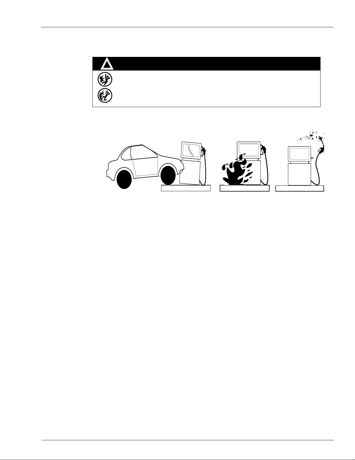
WARNING
Spilled fuels, accidents involving pumps/dispensers, or uncontrolled fuel flow create a
serious hazard.
Fire or explosion may result, causing serious injury or death.
Follow established emergency procedures.
DEF is non-flammable. However it can create a slip hazard. Clean up spills promptly.
!
Collision of a Vehicle with Unit Fire at Island Fuel Spill
The following actions are recommended regarding these hazards:
Important Safety Information
• Do not go near a fuel spill or allow anyone else in the area.
• Use station EMERGENCY CUTOFF immediately . Turn off all system circuit breakers to the island(s).
• Do not use console E-STOP, ALL STOP, and PUMP STOP to shut off power. These keys do not
remove AC power and do not always stop product flow.
• Take precautions to avoid igniting fuel. Do not allow starting of vehicles in the area. Do not allow
open flames, smoking or power tools in the area.
• Do not expose yourself to hazardous conditions such as fire, spilled fuel or exposed wiring.
• Call emergency numbers.
MDE-4331M Atlas® Fuel Systems Installation Manual · September 2014 Page 2-3
Page 16

Important Safety Information
This page is intentionally left blank.
Page 2-4 MDE-4331M Atlas® Fuel Systems Installation Manual · Sep tember 2014
Page 17
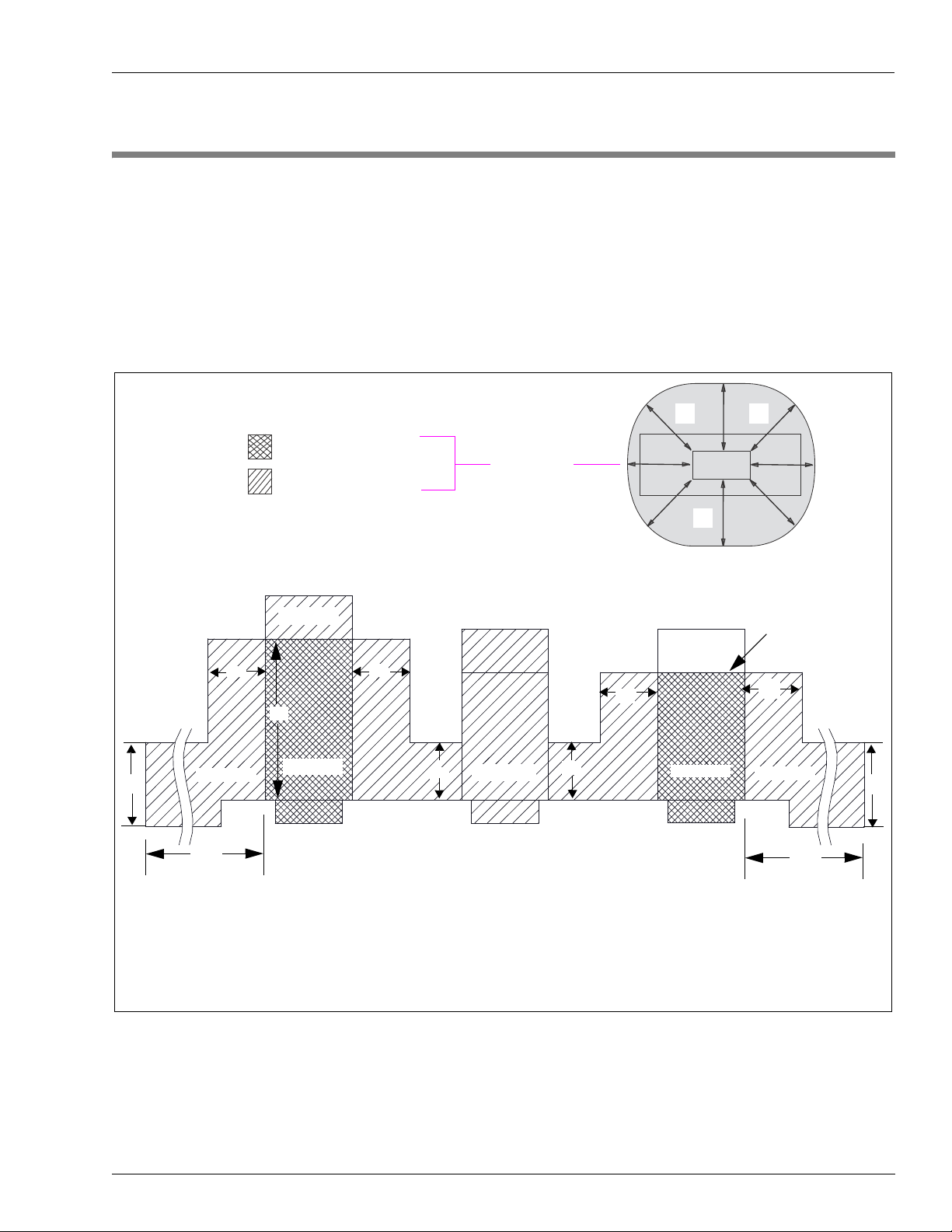
Classifying Hazardous Locations Hazardous Locations
20'
20'
20'
*DEF dispensers located outside the 20 feet area are unclassified.
Notes: 1) Not applicable to DEF-only dispensers.
2) DEF is not flammable and does not generate explosive vapors. For any requirements, consult local regulatory agencies. For
example, units dispensing DEF and diesel must follow the flammable fuel regulatory requirements.
20’
18”
Unclassified
18”
Vapor Barrier
20’
DEF
18”
18”
18”
48”
Division 1
Division 2
Division 2
Division 2*
18”
18”
18”
Division 1
Division 2
Dispenser Without Vapor
Barrier Construction
Dispenser with Vapor
Barrier Construction
Class 1 Division 1
(Hazardous Location)
Class 1 Division 2
(Hazardous Location)
Vapor Areas
Fuel Containing
Components
3 – Hazardous Locations
Classifying Hazardous Locations
Any activity (such as smoking or drilling) that can cause an explosion must be done well
outside the vapor area.
Figure 3-1 is b
Figure 3-1: Hazardous Locations Diagram
sed on National Fire Protection Association (NFPA) 30A and NFPA 70®.
a
MDE-4331M Atlas® Fuel Systems Installation Manual · September 2014 Page 3-1
Page 18

Hazardous Locations Important Considerations for DEF Dispensers
Applicable during installation and operation of the dispenser: DEF freezes at
approximately 11 °F (-11.5 °C). Power to the dispenser and heater must always remain
ON in cold weather. If power is lost and the temperature dro ps below this point, the
system must be inspected for freeze damage before restart. For sites that experience
occasional power losses or for sites that are located in very cold climates, it is
recommended that a backup power generator be used to maintain constant power to the
dispenser. Do not use any additives to lower the freezing point of DEF. Additives of any
type must not be used in DEF.
Prolonged storage at temperatures above 77 °F (25 °C) can impair the quality of DEF
and reduce its shelf life.
CAUTION
DEF is mildly corrosive. It can corrode components that are made from incompatible
material(s) and reduce their integrity. The use of incompatible material(s) may lead to
leaks and spills, and can contaminate and degrade the DEF. When dispensing DEF,
verify with the manufacturer if the material of all plumbing components are compatible
with the DEF being dispensed.
CAUTION
Do not use prover cans meant for engine fuel with DEF or vice versa. Use stainless steel
prover cans for DEF. DEF and engine fuel must not be mixed with each other or be
contaminated by each other. Otherwise, damage to a vehicle’s engine or pollution control
devices can occur. DEF crystallizes as its water base evaporates. Pouring out liquid will
not guarantee that no corrosive DEF remains in the prover can. DEF must not be
contaminated with diesel fuel, contaminants, or other fluids or materials. Such
contamination can cause serious damage to vehicle catalytic converters.
CAUTION
Important Considerations for DEF Dispensers
• Conventional fluid handling precautions are also applicable to DEF.
• Avoid contact with eyes, skin, and clothing. Ensure that
eyewash stations and safety
showers are close to the work location.
• DEF is mildly corrosive and non-flammable.
• Clean the DEF spill with water and dry the area wit
h clean rags, especially areas that
contain metallic parts. Spilt DEF can be slippery and will corrode certain types of metallic
parts. Wear eye protection and rubber gloves during any cleanup activity.
• DEF is heavier than gasoline. Be aware that prover cans, containers filled with DEF, and
so on, will be
considerably heavier than gasoline.
Page 3-2 MDE-4331M Atlas® Fuel Systems Installation Manual · September 2014
Page 19

Purpose Control Lines for Atlas Electronic Series
4 – Control Lines for Atlas Electronic Series
Purpose
This section is provided to familiarize the installer with control inputs and outputs that are
available for the Atlas electronic series dispensing unit. It is recommended that installers read
these descriptions to obtain a better working knowledge of the unit to guide them in planning
the site wiring. For specific wiring diagrams and installation notes, refer to “Installation”
on page 6-1.
Grounding
Atlas electronic series units may be provided for
use with 230 VAC power for international
applications. The operating voltage for control lines to these units is shown in parentheses as
(230 VAC International).
If you are connecting the Atlas electronic series unit to a Gasboy Fuel Management System
(FMS), refer to the following documents:
Document
Number Title GOLD Library
MDE-4298 CFN Series Site Controller III Installation Manual Gasboy CFN Series
MDE-4319 TopKAT Fuel Management System Installation Manual Gasboy Series 1000/Fleetkey &
MDE-4811 Islander PLUS and ICR PLUS Installation Manual Gasboy Fleet PLUS System
MDE-4813 CFN Plus Installation Manual Gasboy Fleet PLUS System
MDE-5013 TopKAT PLUS Installation Manual N/A
TopKAT
To ensure proper operation of the equipment and required safety factors, a good ground line
must be provided. A ground wire (preferably green) must be connected between the ground
wire of the system and the main electrical service panel. One earth ground connection is
required per unit. The ground rod must be a solid, corrosion-resistant conductor and must be
installed at the main electrical panel as per the National Electrical Code (NEC). It must be
properly tied into the ground bus strip of the panel. It is recommended that n eutral and g round
bus strips be bonded together (unless prohibited by local codes).
Ground Fault Interrupter (GFI) breakers are required for DEF
only units installed on and with
a skid tank platform because of no underground piping, AC power in potentially wet area, and
a potential for earth ground to become broken if skid tank moves.
A GFI works by having a sensor that detects changes in current to the load, by comparing the
current owing to and from the load. A drop off in the current equivalent to about 5 mA, turns
off all power by tripping a relay within the GFI within a few hundredths of a second.
When powering a dispenser with a GFI, any device that the dispenser supplies power must
have its return to the same neutral as the dispenser. For example, the STP control relay.
MDE-4331M Atlas® Fuel Systems Installation Manual · September 2014 Page 4-1
Page 20

Control Lines for Atlas Electronic Series Micro Feed
Micro Feed
The micro feed is a 115 VAC (230 VAC international) input required to power the
microprocessor of the register’s electronics. This power must always remain on and must be
on a separate breaker from control lines (control/pump motor feed or control/submersible
feed - side 1, side 2). It must also be on a separate
electrical noise and allow separate control of lights. In a site configuration using multiple
dispensing units, the power for microprocessors of up to eight units can be supplied by one
breaker (except cold weather DEF units). This line also supplies power to the optional
T opKAT PLUS. If this unit is equipped with a TopKAT PLUS option, for wiring requirements
and information, refer to MDE-5013 TopKAT PLUS Installation Manual.
breaker from fluorescent lights to reduce
The cold weather DEF unit’s internal heater ca
circuit. These units must not share breakers with other dispenser.
n share the micro feed AC line and neutral
Micro Neutral
The micro neutral is a return line for AC from the microprocessor of the dispensing unit to the
breaker panel. This line also serves as the return for the optional TopKAT PLUS.
Auth/Pump Motor Feed (Self-contained Pumping Units)
The auth/pump motor feed is a 115 VAC (230 VAC international) input that is required to
power and authorize the auth control line. This line is used to provide authorization for the
self-contained pumping unit (when enabled, refer to MDE-4334 Atlas Start-up/Service
Manual). If this line is controlled by an FMS using solid state relays, a resistor assembly must
be installed between the auth feed line and feed neutral to prevent false triggering of the
authorization input. The resistor assembly is 8.2 K Ohm, 10 W (part number C05818) for
115/230 VAC domestic; and 30 K Ohm, 10 W (part number C06683) for 230 VAC
international wiring.
Note: The auth/pump motor feed is not r
The auth/pump motor feed line is used to powe
installed). The power used to control the pump is also provided by this line. It is possible to
combine control lines for twins and supply them from one breaker. However, the gauge of the
wire must be adjusted to handle the load of two motors. The reset complete signal used for
external monitoring of the pump also originates from the auth/pump motor feed line.
Two auth/pump motor feed lines are provided for twins.
equired for the TopKAT PLUS system.
r slow flow and fast flow valves (when
Page 4-2 MDE-4331M Atlas® Fuel Systems Installation Manual · September 2014
Page 21

External Valve Control Lines for Atlas Electronic Series
External Valve
The external valve line is used to directly power an anti-siphon valve mounted on top of an
AST . The valve must operate at the same voltage as the pump motor and the current draw must
not exceed 1 A, or the valve must be switched through an external relay controlled by the
external valve line. Do not connect two or more external valve lines together. If more than one
pump is drawing from the tank, separate anti-siphon valves must be installed, or each external
valve line must operate an external relay, which then operates the valve.
Neutral Feed
The neutral feed is the AC current return line back to the breaker panel for all attached devices
(pump motor, reset motor, and solenoid valves).
Auth Input Dispensers
The auth input is a 115 VAC (230 VAC international) input that is required to power and
authorize the auth control line. This line is used to provide authorization for the dispensing
unit (when enabled, refer to MDE-4334 Atlas Start-up/Service Manual). If this line is
controlled by an FMS using solid state relays, a resistor assembly must be installed between
the auth feed line and feed neutral to prevent false triggering of the authorization input. The
resistor assembly is 8.2 K Ohm, 10 W (part number C05818) for 115/230 VA C domestic and
30 K Ohm, 10 W (part number C06683) for 230 VAC international wiring. Cash Flow
Network (CFN) systems require the resistor assembly only when they are used with the Atlas
commercial electronic pump/dispenser operating in standalone mode. Operating the Atlas
commercial electronic unit in standalone mode with a CFN system requires an optional
mechanical pump control unit. This line also supplies power, which is switched to slow flow
and fast flow valves along with the switch detect signal. Two lines are provided for twins.
If the Atlas commercial electronic unit is to be controlled t
special care must be taken in the wiring of submersible control lines when a common
submersible is used for more than 1-hose outlet. For more information, refer to “Submersible
Starter Drive (Subm Starter Drive)” and “Submersible Pump Drive (Subm Pump Drive)”
on page 4-4.
hrough the authorization of this line,
Units with Standard Submersible Starter Drive (Subm Starter Drive)
Power for the submersible start drive line originates from the AUTH input. The submersible
starter relay line in standard remote dispensers is not capable of directly powering a
submersible pump. A starter relay must be used. Control lines for twin remote dispensers can
be combined together and powered by one breaker if individual control of each side is not
required. In site configuration using multiple remote dispensers, power for control lines of up
to 8-hose outlets (eight singles or eight twins) can be supplied from one breaker.
MDE-4331M Atlas® Fuel Systems Installation Manual · September 2014 Page 4-3
Page 22

Control Lines for Atlas Electronic Series Submersible Starter Drive (Subm Starter Drive)
Units with Submersible Pump Drive Relay Option
Power for the submersible pump drive line originates from the motor feed input. Units
equipped with optional relays for direct submersible pump drive can be connected directly to
submersible pumps up to 3/4 HP at 115 VAC, or 1-1/2 HP at 230 VAC. The gauge of this wire
must be determined according to the size of the motor, the voltage at which the motor will be
powered, and the distance from the breaker panel to the pump.
Submersible Starter Drive (Subm Starter Drive)
The submersible starter drive is a 115 VAC (230 VAC International) output used to control a
submersible starter relay. Two lines are provided for twins. This line is capable of supplying
300 mA of AC current to control the coil of the submersible motor contactor (starter relay).
This is sufficient for directly connecting to popular models, but if in doubt, check the contactor
(relay) manufacturer’s data sheet for the sealed VA rating. Divide the sealed VA by the coil
voltage to determine the current. This line must not be connected directly to the submersible
pump, shorted to any conduit or chassis metal, or incorrectly wired; otherwise, the Central
Processing Unit (CPU) Printed Circuit Board (PCB) will be instantly damaged. This line must
be left capped when not in use. To avoid accidental damage, follow checks before applying
power.
Note: When multiple dispensers are used to contr
pump, and the Atlas commercial electronic unit is controlled (authorized) through the
auth/pump motor feed line (as in the case of some FMSs), it is important that lines from
the Atlas commercial electronic unit to the submersible equipment be isolated from
each other. This can be accomplished by running submersible control lines through a
secondary set of relay contacts in the FMS. If a secondary set of contacts is not
available, external control re lays must be used between the Atlas commercial electr onic
unit and the submersible starter relay or pump. Another option is to provide a separate
submersible starter relay for each hose outlet. In no case must the submersible drive
lines from the Atlas commercial electronic unit be tied together.
ol a common submersible starter relay or
Submersible Pump Drive (Subm Pump Drive)
The submersible pump drive is not available on all Atlas models for remote dispensers, and is
active only when submersible drive relays are supplied. The submersible drive is a
115/230 VAC (230 VAC international)
submersible pump. When connected directly to the submersible pump, the motor size cannot
exceed 3/4 HP at 115 VAC, or 1-1/2 HP at 230 V AC. Two lines are provided for twins. In cases
where both lines control the same starter relay or pump, they can be combined. This line is
also used to control an external valve used on AST installations.
Note: For situations where more
to the note in “Submersible Starter Drive (Subm Starter Drive)”.
output used to control the submersible starter relay or
than one-hose outlet uses the same submersible pump, refer
Page 4-4 MDE-4331M Atlas® Fuel Systems Installation Manual · September 2014
Page 23

Reset Complete (Switch Detect)/Slow Flow Control Lines for Atlas Electronic Series
Reset Complete (Switch Detect)/Slow Flow
The reset complete/slow flow is a 115 VAC (230 VAC international) output used to indicate
that the reset process is complete and the unit is ready to dispense the product. It may be
required when used with an FMS. It may also be used to control a remote (satellite)
slow flow valve. Two lines
are provided for twins.
In addition to the internal load of the slow flow valve,
maximum of 170 mA AC to the satellite valve and FMS. When you are connecting it to a
non-Gasboy satellite or FMS, ensure that this limit is not exceeded. This line must not be
shorted to any conduit or chassis metal, incorrectly wired, used to control both stages of a
satellite valve, or be connected to equipment requiring more than 170 mA AC from this line to
operate; otherwise, the CPU PCB will be instantly damaged. This line must be left capped
when not in use. To avoid accidental damage, follow checks before applying power.
Fast Flow Valve
The fast flow valve is a 115 VAC (230 VAC International) line that can be used to control a
remote (satellite) fast flow valve. Two lines are provided for twins. In addition to the internal
load of the fast flow valve, this line is capable of supplying 170 mA AC to the satellite valve.
When connected to a non-Gasboy satellite, ensure that this limit is not exceeded. This line
must not be shorted to any conduit or chassis metal, incorrectly wired, used to control both
stages of a satellite valve, or be connected to equipment requiring more than 170 mA from this
line to operate; otherwise, the CPU PCB will be instantly damaged. This line must be left
capped when not in use. To avoid accidental damage, follow checks before applying power.
Phase 2 Feed
this line is capable of supplying a
The phase 2 feed is a hot feed, which is the opposite phase of pump motor feed. This line and
pump motor feed are used for 230 VAC domestic motor applications. If connected to
equipment requiring control of the authorization input, phase 2 feed must be switched through
a separate relay to prevent false triggering of the authorization signal.
Slow/Fast Satellite Return
The slow/fast satellite return lines are used only in units that come equipped with satellite
piping. They are used in applications where the remote dispenser and satellite may not
dispense the product at the same time. These lines are not connected internally as they leave
the factory . Four lines ar e provided for twins. These lines must not be shorted to any conduit or
chassis metal, or be connected to equipment requiring more than 170 mA from each line to
operate; otherwise, the CPU PCB will be damaged instantly. These lines must be left capped
when not in use. To avoid accidental damage, follow checks before applying power.
MDE-4331M Atlas® Fuel Systems Installation Manual · September 2014 Page 4-5
Page 24
Control Lines for Atlas Electronic Series Light Feed
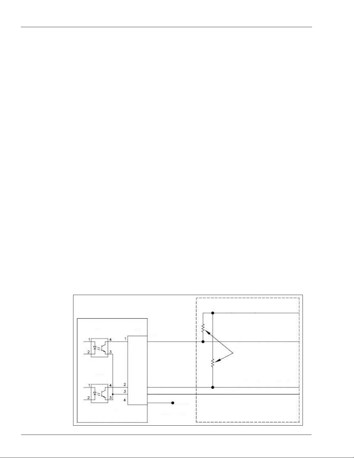
V+ (24 VDC Maximum)
Pulser #1 Input (100 mA Maximum)
Pull-up Resistors not
supplied with 9800
Pulser #1 Input (100 mA Maximum)
FMS
Ground
Pulse 1
Pulse 2
Return
Black
White
Green
Gasboy 9800 Pump I/F PCB
Leave Capped in
9800 Junction Box
(J-box)
TLP627
U4
P1
Red
Light Feed
The light feed is a 115 VAC input required to power fluorescent lights. In a site configuration
using multiple remote dispensers (or pumps), the power for lights of up to eight units can be
supplied by one breaker. It is recommended that this be on a separate breaker from the
micro/heater feed to reduce electrical noise and allow separate control
of lights.
Light Neutral
The light neutral is a return line for AC current from lights to the breaker panel. When a
separate breaker is not used to control lights, the light neutral is attached to the micro neutral.
Pulser
When the dispensing unit includes the optional pulser interface, a pulser output is provided.
This pulser output provides a DC output that indicates the quantity of product dispensed. The
pulse rate can be configured by a sealable Dual In-line Package (DIP) switch for rates of 1, 10,
100, 250, or 500 pulses per gallon, or 1, 10, 100, or 250 pulses per liter. For the Atlas
commercial electronic pump, pulse rates are 1, 10, 100, 250, or 500 pulses per gallo n, or 1, 10,
or 100 pulses per liter.
The output is an open collector transistor capable of sinking up to 100 m A DC at voltages up
to 24 VDC. The
DC ground for the circuit comes from the FMS. Since the transistor switches
between ground and high impedence, the installer must provide a voltage reference when the
transistor is in the high impedence state. This reference voltage is provided by a pull-up
resistor installed at the FMS between the pulser input and reference voltage. The value of this
resistor is calculated based on the voltage and current requirements of the FMS pulser circuit.
Figure 4-1: Pulsers
Page 4-6 MDE-4331M Atlas® Fuel Systems Installation Manual · September 2014
Page 25

RS-485 Control Lines for Atlas Electronic Series
In the main J-box, the optional pulser interface is supplied with eight wires. On Ultra-Hi units,
a separate DC J-box with six wires is supplied. The unused wires in the J-box must be
individually capped.
RS-485
When the dispensing unit includes the optional RS-485 interface, RS-485 lines are provided.
This interface allows you to connect a Gasboy CFN series system directly to the Atlas
commercial electronic series dispensing unit. These lines must be capped individually when
not in use. The RS-485 interface is included with the TopKAT PLUS option.
Local Area Network (LAN)/Wide Area Network (WAN)
When the dispensing unit includes the optional T opKAT PLUS, lines for communication to the
TopKAT PLUS are provided. These lines allow you to communicate directly to the TopKAT
PLUS through a LAN/WAN connection. For more information on LAN/WAN wiring, refer to
MDE-5013 TopKAT PLUS Installation Manual.
MDE-4331M Atlas® Fuel Systems Installation Manual · September 2014 Page 4-7
Page 26

Control Lines for Atlas Electronic Series Local Area Network (LAN)/Wide Area Network (WAN)
This page is intentionally left blank.
Page 4-8 MDE-4331M Atlas® Fuel Systems Installation Manual · September 2014
Page 27

Purpose Control Lines for Atlas Mechanical Series
5 – Control Lines for Atlas Mechanical Series
Purpose
This section is provided to familiarize the installer with control inputs and outputs that are
available for the Atlas mechanical series dispensing unit. It is recommended that installers
read these descriptions to obtain a better working knowledge of the unit to guide them in
planning the site wiring. For specific wiring diagrams and installation notes, refer to
“Installation” on page 6-1.
Grounding
The Atlas mechanical series may be provided fo
applications. The operating voltage for control lines to these units is shown in parentheses as
(230 VAC international).
If you are connecting the Atlas mechanical unit to a Gasboy FMS, refer to the following
documents:
Document
Number Title GOLD Library
MDE-4298 CFN Series Site Controller III Installation Manual Gasboy CFN Series
MDE-4319 TopKAT Fuel Management System Installation Manual Gasboy Series 1000/Fleetkey & TopKAT
MDE-4811 Islander PLUS and ICR PLUS Installation Manual Gasboy Fleet PLUS System
MDE-4813 CFN Plus Installation Manual Gasboy Fleet PLUS System
MDE-5013 TopKAT PLUS installation Manual Gasboy Series 1000/Fleetkey & TopKAT
To ensure proper operation of the equipment and required safety factors, a good ground line
must be provided. A ground wire (preferably green) must be connected between the unit’s AC
J-box ground lug and main electrical service panel. One earth ground connection is required
per unit. The ground rod must be a solid, corrosion-resistant conductor that must be installed at
the main electrical panel as per the NEC. It must be properly tied into the ground bus strip of
the panel. It is recommended that the neutral and ground bus strips be bonded together (unless
prohibited by local codes).
r use with 230 VAC power for international
GFI breakers are required for DEF only units installed on and
because of no underground piping, AC power in potentially wet area, and a potential for earth
ground to become broken if skid tank moves.
A GFI works by having a sensor that detects changes in current to the load, by comparing the
current owing to and from the load. A drop off in the current equivalent to about 5 mA, turns
off all power by tripping a relay within the GFI within a few hundredths of a second.
When powering a dispenser with a GFI, any device that the dispenser supplies power must
have its return to the same neutral as the dispenser (for example, the STP control relay).
MDE-4331M Atlas® Fuel Systems Installation Manual · September 2014 Page 5-1
with a skid tank platform
Page 28

Control Lines for Atlas Mechanical Series Reset Motor Feed
Reset Motor Feed
The reset motor feed is a 115 VAC (230 VAC international) input supplied through the pump
handle switch to activate the reset motor. Without power being supplied to this line, the unit
will not reset when the pump handle is turned on. Two feed lines are provided for twins. This
feed is also connected to the input of one of the internal switches of the electric reset. When
the reset finishes its cycle, the 115 VAC (230 VAC international) input to the switch will be
passed through as an output, causing the solenoid valve (optional in some models) to open and
the reset complete line to indicate 115 VAC (230 VAC international).
Pump Motor Feed
The pump motor feed is a 115 VAC (230 VAC international) input supplied to the input side of
one of the internal switches of the electric reset. When the reset finishes its cycle, the
115 VAC (230 VAC international) input to the switch
the pump motor to receive power and begin operation. Without power to this line, the unit will
reset and will be unable to fuel. Two feed lines are provided in twins that contain two motors.
The gauge of this wire (and its neutral wire) must be determined according to the size of the
motor, the voltage at which the motor will be powered (115 VAC or 230 VAC), and the
distance from the breaker panel to the pump. It is possible to combine pump motor feeds for
twins and supply them from one breaker. However, the gauge of the wire must be adjusted to
handle the load of two motors.
is passed through as an output, causing
Return (Neutral)
The return is the AC current return line back to the breaker panel for all attached devices
(pump motor, reset motor, and solenoid valves). The gauge of this wire must be equal to that of
the pump motor feed (suction pumps) or submersible feed (remote dispensers). This wire is
commonly referred to as the neutral wire.
Submersible Feed, Submersible Drive
The submersible feed is a 1 15 VAC (230 VAC international) input supplied to the input side of
one of the internal switches of the electric reset. When the reset finishes its cycle, the
115 VAC (230 VAC international) input to the switch is pas
(submersible drive) to drive a starter relay or to directly drive a submersible motor up to one
HP at 115 VAC/230 VAC. Any submersible motor exceeding this limitation must use a starter
relay.
sed through as an output
Reset Complete (Switch Detect)/Slow Flow
The reset complete is a 115 VAC (230 VAC international) output used to indicate that the reset
is complete and the dispensing unit is ready to dispense the product. T wo lines are provided for
twins. Use this line only when monitoring a dispensing unit that is connected to a FMS. This
line must be capped when not in use, and is connected to the slow-flow stage of the solenoid in
the pump.
Page 5-2 MDE-4331M Atlas® Fuel Systems In stallation Manual · September 2014
Page 29

Fast Flow Control Lines for Atlas Mechanical Series
Fast Flow
The fast flow is a 115 VAC (230 VAC international) input that controls the fast flow valve of
the pump/remote dispenser (when a slow/fast flow valve is available). If slow/fast-flow
control is not required, this line must be tied to reset the complete/slow-flow line. The line
must be switched through the FMS and be turned on only when the pump/remote dispenser is
authorized and in the fast-flow mode. This line will be switched on when the pump/remote
dispenser is in the manual mode.
Light Feed
The light feed is a 115 VAC (230 VAC international) input required to power fluorescent
lights. In a site configuration using multiple remote dispensers (or pumps), power for lights for
up to eight units can be supplied by one breaker. If separate control of lights is not required,
the light feed for each dispensing unit may be taken from its reset motor feed, provided the
unit is not connected to a FMS.
Light Neutral
The light neutral is a return line for AC from lights to the breaker panel. When a separate
breaker is not used to control lights, the light neutral is attached to the neutral, which is
connected to the reset motor.
Phase 2 Feed
The phase 2 feed is a hot feed, which is the opposite phase of pump motor feed. This line and
pump motor feed are used for domestic 230 VAC motor applications.
Pulser
The pulser supplies a DC output that indicates the quantity of product dispensed. Pulsers are
optional and are used only when monitoring the dispensing unit that is connected to a FMS.
The pulser wiring must run in a separate conduit away from AC power control lines.
MDE-4331M Atlas® Fuel Systems Installation Manual · September 2014 Page 5-3
Page 30

Control Lines for Atlas Mechanical Series Pulser
This page is intentionally left blank.
Page 5-4 MDE-4331M Atlas® Fuel Systems In stallation Manual · September 2014
Page 31

Purpose Installation
6 – Installation
Purpose
This section provides information specific to the installation of Atlas pumps/dispensers.
Required Equipment and Materials
DEF is not flammable or explosive. Therefore, installation requirements for DEF units differ
from units that handle hazardous fuels. However, electrical safety requirements are applicable.
When installing a DEF unit in a hazard zone defined by the location of another
pump/dispenser handling hazardous fuels, the are
zone must conform to requirements for units handling hazardous fuels.
a of the DEF dispenser within the hazard
Following items are required for the installation
• Anchor bolts
• UL-approved sealant (for use with fuels being encountered)
• Pit box cover plates (for use when it is required to
• Lifting device (forklift) to move and lift pumps/dispensers
• Breakaways, hoses, nozzles, and swivels
• Approved wire nuts
• Barricades
• Potting compound and fiber dam material
division II locations, as specified in the NEC)
of the equipment:
(to allow potting of conduit as per class I,
Important Requirements for E85 Units
Following equipment and materials are required to properly install E85 units:
UL-listed E85 Hose (Q13486)
SM
• Veyance
• Veyance
Note: Extended reach hoses are not available for the E85 applications.
UL-listed E85 Nozzle (M11298)
®
21GE
OPW
Note: Approved for use with the E85 dispenser
Flexsteel™ Futura® Ethan-All for E85
Flexsteel Futura for E25
s, as required under UL 87A.
adapt the unit to pre-existing pit boxes)
UL-listed E85 Swivel (N23748-04)
OPW 241 TPS-0492
Note: Approved for use with E85 dispe
MDE-4331M Atlas® Fuel Systems Installation Manual · September 2014 Page 6-1
nsers, as required under UL 87A.
Page 32

Installation Important Considerations when Changing Fuel Types
For E85 front load units, side B is the side with the J-box. For more information on nozzle
boot positioning for the different models, refer to “Foundation Diagrams” on page A-3.
IMPORTANT INFORMATION
Certain special alternative fuels, such as E85 and additives, can degrade
pump/dispenser performance or integrity if the dispensers are not designed for use with
such fuels. Additionally, converting to certain standard fuels (gasoline, diesel, kerosene,
and so on) from alternative fuels, such as those with ethanol (E85), methanol, or
biodiesel, or from alternative fuels to standard fuels can degrade dispenser performance
or integrity. Similar effect s can also occur when converting units to different standard fuel
types.
As per UL 87A requirements, nozzles dispensing E85 fuel must not be used to
dispense any other type of fuel such as Gasoline.
Leaks and potential environmental hazards can result or components may fail
prematurely.
To avoid these issues, follow the guidelines in this section.
WARNING
UL-listed E85 Shear Valve (T19695-23)
OPW 10P-0152E85
Note: Approved for use with E85 dispensers, as
required under UL 87A.
UL-listed E85 Breakaway (N23010-10)
OPW 66V-0492
Note: Approved for use with E85 dispensers, as
required under UL 87A.
Filter
Use only filters specifically marked for use with E85.
UL-listed Pipe Sealant
A
Use only UL-listed TPS PTFE pipe sealant manufactured by S
F-T-LOC International Corp.
UL-listed Teflon
®
Tape
Use only UL-listed Taega Technologies Inc. Teflon tape.
Note: Teflon tape must be used only at the inlet pipe connection.
Important Considerations when Changing Fuel Types
Follow the guidelines given below when changing fuel types for a pump/dispenser or using
alternative fuels or fluids:
Page 6-2 MDE-4331M Atlas® Fuel Systems In stallation Manual · September 2014
• Verify with your Gasboy ASC or distributor if the
fuel you will be using is compatible
with the pumps/dispensers dispensing the fuel.
• For flexible fuel dispensers, do not use standard hydrau
lic parts used in other Gasboy
pumps/dispensers for service parts in these units. Standard dispenser parts may not be
compatible with fluids.
Page 33

Important Considerations when Changing Fuel Types Installation
The above guideline does not apply to flexible fuel model dispensers.
IMPORTANT INFORMATION
• Biodiesel fuels must conform to American Society for Testing and Materials (ASTM)
standards for biodiesel fuels. Mixes of diesel with cooking oils, other plant or animal
derived oils, and so on, are not considered biodiesel. Use of such mixes may void warranty
on the hydraulic components of the unit.
• Review the latest copy of the unit’s warranty statement regarding the use of fuel.
Certain fuels (especially fuels en
•
hanced with alcohol) when first used in tanks previously
containing a different fuel may clean out the tanks and force a large amount of
contaminant into the dispenser. Other than abnormally clogging filters, this large quantity
of contaminant may damage certain dispenser components. Do not run units without
filters at such times. It is normally required that tanks and lines be cleaned of all water,
sediment, and contaminant before such conversions to minimize potential
pump/dispenser downtime or damage. Damage to hy
draulic components from
contamination when not using filters is not covered by warranty. For recommendations,
consult your ASC or Gasboy distributor.
• Do not use any equipment that was formerly used to
store or dispense any other fuel or
liquid with DEF. Dispensers designed for use with DEF must only be used with DEF.
• Do not use prover cans meant for engine
• Although conversions from one fuel to an equi
fuel with DEF or vice versa.
valent fuel (say from another supplier)
generally do not create issues, it is recommended that after making any fuel type
conversions (including those to alternative fuels such as E85 or back), all units be visually
inspected for leaks, two days, one week, and one month after fuel conversion. Have your
ASC repair any leaks found. This must also be performed for standard fuels when
significant new additives are incorporated.
• Whenever non-equivalent fuel conversions are performed, it is recommended that all units
be checked for calibration within one month of fuel conversion.
• Some non-equivalent fuel conversions will necessitate the requirement to change the
pump/dispenser
filter type previously used. For any changes requi
red, consult your ASC
or Gasboy distributor.
• In flexible fuel dispensers, Gasboy recommends the
gasoline-based flexible fuels. Although the use of finer filtratio
use of 10 micron filters for
n is allowable, filters will
tend to clog prematurely, causing excessive filter maintenance cost.
• Use only meters and registration devices for DEF that have a National Type Evaluation
Program (NTEP)
Certificate of Compliance issued by the National Conference on Weights
and Measures (NCWM).
• Non-metallic piping and components used in aboveground DEF service must have high
ing points and adequate strength and durability. Some plastic compounds that are
melt
suitable for DEF may not be compatible with petroleum products. They must be avoided
at locations where they can come in contact with petroleum from a routine operation or a
spill.
• An anti-siphon valve must be installed on AST where the DEF level can be at a higher
elevation than the supply p
iping or the dispenser . T he valve will prevent a potential leak in
the piping from creating a siphon that can cause a product release.
MDE-4331M Atlas® Fuel Systems Installation Manual · September 2014 Page 6-3
Page 34

Installation Read NFPA 30A and NFPA 70
You are working in a dangerous environment of gasoline, gasoline vapor, and electricity.
Failure to install this equipment in accordance with NFPA 30A and NFPA 70 can result in
severe injury or death. Read, understand, and follow NFPA 30A and NFPA 70.
WARNING
Failure to install the equipment as per the NFPA 30A and NFPA 70 may adversely affect
the safe use and operation of the system.
CAUTION
Read NFPA 30A and NFPA 70
DEF is not flammable or explosive. Therefore, installation requirements for DEF units differ
from units that handle hazardous fuels. However, electrical safety requirements are applicable.
When installing a DEF unit in a hazard zone defined by the location of another
pump/dispenser handling hazardous fuels, the area
zone must conform to requirements for units handling hazardous fuels.
Before installing the equipment, read, understand, and follow:
• The NEC (NFPA 70)
• The Automotive and Marine Service Code (NFPA 30A)
• Any national, state, and local codes that may apply
of the DEF dispenser within the hazard
Accurate, sound installations reduce service calls. Use experienced, licensed contractors that
practice accurate, safe installation techniques. Careful installation can eliminate potential
problems.
The equipment manufacturer must provide instructions for other equipment such as STPs,
shear valves, and underground tanks. Complete installation instructions for other
manufacturer’s equipment are not provided.
Preparing for Installation
To prepare for the installation, proceed as follows:
1 Read all instructions before beginning the installation.
2 Follow all safety precautions:
• Barricade the area.
• Do not allow vehicles or unauthorized people in the work area.
• Do not smoke or allow open flames in the work area.
• Do not use power tools in the work area.
• Wear eye protection during the installation.
• Use circuit breakers to turn off all power to pumps/dispensers
disconnects may be required.
and STPs. Multiple
Page 6-4 MDE-4331M Atlas® Fuel Systems In stallation Manual · September 2014
Page 35

Preparing for Installation Installation
3 Check the following for proper installation, as per the criteria specified in MDE-4333 Atlas
Fuel Systems Site Preparation Manual, and other manufacturer’s recommendations that apply:
• Emergency Power Cut-off Switch
• Circuit Breakers
• STP Control Relay Boxes - Dispensers only (see Notes)
• Isolation Relays - Dispensers only (see Notes)
• Breakaways, hoses, nozzles, and swivels (refe
r to “Installing Breakaways, Hoses, Swivels,
and Nozzles” on page 6-18)
• Conduit and Wiring (see Notes)
• Grounding
• Shear Valves - Dispensers only (see Notes)
• Piping and Fittings
• Fuel Storage Tanks
• Pressure Regulating Valves (a
boveground tanks only)
• STP - Dispensers only
• Tank and/or Line Leak Detectors
• Pit Boxes
Notes: 1) A shear valve is an NFPA 30A recommende
d safety device required for every
product line at each dispenser. For installation instructions, r e fer to MDE-4333
Atlas Fuel Systems Site Preparation Manual. Shear valves may also be r equired
for aboveground tank installations and other situations with pumps. Consult
local and state requirements.
2) Refer to MDE-4334 Commercial and Retail
Series Atlas Start-up/Service
Manual.
3) Some locations require shear valves for
vapor lines. Consult local and state
regulations.
4) The 9862 Atlas DEF units uses a special
stainless steel shear valve made by
OPW.
4 Inspect the pump/dispenser cartons and contents for shipping damage. Gasboy does not cover
shipping damage under its warranty policy. Notify the shipper of any damage.
5 Remove the bezel and lower panels (doors) of the pump/dispenser, refer to MDE-4334
Commercial and Retail Series Atlas Start-up/Service Manual.
6 Ensure that the fuel grade for product lines matches the pump/dispenser brand panels and
foundation layout. Product lines from the island pit box must have labels.
MDE-4331M Atlas® Fuel Systems Installation Manual · September 2014 Page 6-5
Page 36

Installation Before Placing Unit on Fuel Island
High alcohol percentage fuels such as E85 or fluids such as DEF may be incompatible
with certain plumbing materials and hydraulic components.
Use of incompatible materials or components with E85 or DEF can result in leaks. For
E85, unexpected failures of components may also occur resulting in fire or explosion or
environmental damage. When installing components in E85 units, refer to “Important
Requirements for E85 Units” on page 6-1.
When dispensing alternative fuels such as E85 or fluids such as DEF, verify with the
manufacturer if the material of all plumbing components are compatible with the fuel
(E85) or fluid being dispensed.
WARNING
Do not make assumptions about configurations based on previous experience, hose
positions, or layout of the unit being replaced, whether replacing a Gasboy unit or that
of any other manufacturer.
IMPORTANT INFORMATION
Before Placing Unit on Fuel Island
Note: Before mounting the unit on to the fuel island, read and understand this section
completely. This information is essential to avoid installation errors.
Verifying and Determining Plumbing Requirements
Before placing the unit on an island, determine the correct location of piping and orientation of
the unit involved. A common installation error is to install the unit backwards, which results in
expensive modification for reinstallation later. This section contains information regarding
plumbing requirements for various models.
Determining the Unit Orientation
To ensure proper unit orientation, perform the following:
• Mount the unit using the mounting bolt locations specified. Seal the base
• Fill in any openings to the potentially larg
er pit box opening. Seal as required.
• DEF cold weather units are front load units. Ensure that the hose can
180 degrees from the front of the unit. That is, the hose is not
used at a position directly
as required.
be used at only
behind the unit. Reorientation of the unit may be required to avoid operation in this
manner.
Determining the Unit Side and Type
Before lifting units on to the island, ensure the following:
• To determine the unit type, refer to the unit’
Note: The model sticker is located at particular place
Page 6-6 MDE-4331M Atlas® Fuel Systems In stallation Manual · September 2014
• To locate the appropriate configuration for your unit, refer to “Foundation Diagrams” on
• DEF cold weather units are front load only units. DEF warm weather units can be
bezel. In mechanical units, it is on the inside, left side of the top housing. In
electronic computer units, it is on the electronics base plate in the front of the top
housing.
page A-3.
load or front load units.
s model sticker.
s and can be viewed by removing the
side
Page 37

Lifting Units Installation
Applicable for fluids other than DEF. You are working in a potentially hazardous
environment where fuels and their vapors may be present and can be ignited with sparks
from grinding and cutting tools. Ensure that sparks or open flames are not generated
when you modify a rain lip where fuel or fuel vapors may be present.
WARNING
Lifting heavy equipment can be hazardous. Equipment can fall, and cause severe injury
or death. Use lifting equipment of proper capacity and factor of safety when moving or
positioning the unit. Stand clear from the pump/dispenser when lifting, lowering, or
transporting.
WARNING
Adapting Pit Box
For installation using an existing pit box, some modifications may be required. Following list
highlights the changes that may be required. These installation considerations may also apply
when replacing competitive units.
To adapt plumbing/conduit to stub-up locations, ensure
Lifting Units
the following:
• Use flexible piping in the pit bo
• When adapting a unit to an existing pit box or one that
x for plumbing adaptation.
is not specifically designed for the
unit, the rain lip may require modification or removal. If the rain lip is removed, then the
entire base of the dispenser must be sealed to the island. Study foundation layouts and the
existing pit box to determine if modifications are required, before mounting the unit on the
island.
• When adapting for an Atlas model 9850KXTW1, refer to “Model 9850KXTW1 Shear
Valve Configuration” on page 6-10.
• For working in this area, refer to the following warning:
Before mounting the unit to the island, ensure that the pit box and unit base are compatible.
Some pit box plates have rain lips that require modification before placing the unit on plate.
Lifting Units with Forklift
To lift units with a forklift, proceed as follows:
1 Ensure that the weight of the pump/dispenser is equally distributed on the tines to the forklift.
2 Lift and guide the unit, positioning it on to the island.
MDE-4331M Atlas® Fuel Systems Installation Manual · September 2014 Page 6-7
Page 38

Installation Connecting Pump/Dispenser Inlet Pipes
Use of incompatible materials or components with E85 or DEF can result in leaks. For
E85, unexpected failures of components may also occur resulting in fire or explosion or
environmental damage. When installing components in E85 units, refer to “Important
Requirements for E85 Units” on page 6-1.
When dispensing alternative fuels such as E85 or fluids such as DEF, verify with the
manufacturer if the material of all plumbing components are compatible with the fuel
(E85) or fluid being dispensed.
Do not replace the dispenser or pump parts with those incompatible with the fuel
involved.
WARNING
WARNING
Shear valves must be installed correctly. Improperly or insufficiently anchored shear
valves can lead to fire or explosion. Fire/explosion can result in severe injury or death.
For DEF units product spills may occur. Anchor all shear valves as per the
manufacturer’s instructions. AST installations require a pressure regulating valve at the
base of the pump.
Applicable to Dispensers Rated for E85 Use:
Do not use tape at the very end of the pipe nipple to avoid tape entering the dispenser
hydraulics. Tape in the hydraulics can cause failures of valves, nozzles, or other
significant problems.
Use only UL-listed TPS PTFE pipe sealant manufactured by SAF-T-LOC International
Corp.
Use only UL-listed Taega Technologies Inc. Teflon tape.
Note: Teflon tape must be used only at the inlet pipe connection.
CAUTION
Connecting Pump/Dispenser Inlet Pipes
T o aid in the alignment and positioning of piping, it is always recommended that the unit is not
anchored securely to the island until the piping is completely aligned and tightened.
Shear valves are not required in pumps, except in special circumstances. Following procedure
for a pump is identical to that of a dispenser, except that a shear valve may not be used. The
contractor must provide and install pipe unions, irrespective of whether shear valves are used
or not.
For units with shear valves, the
For proper tightening of the union to the shear valve, refer to the “shear valve manufacturer’s
instructions”. For units without shear valves, the contractor-provided union must be installed
on the ground stub pipe.
Page 6-8 MDE-4331M Atlas® Fuel Systems In stallation Manual · September 2014
contractor-provided union must be installed on the shear valve.
Page 39

CAUTION
Shear valves or other dispenser components can be damaged or broken if improper
wrench techniques are used. The installer must use two wrenches, so that stress is not
applied to the shear portion of the valve during tightening.
Connecting Pump/Dispenser Inlet Pipes Installation
Do not use a pry (crow) bar to position the pump/dispenser over the conduit or pipes.
This can damage valves, conduit, or other parts of the unit. Do not stress the unit’s
hydraulics, mounting frame, mechanical computer, and so on, by attempting to connect
parts that are vertically too sh ort .
CAUTION
For model 9850KXTW1, refer to “Model 9850KXTW1 Shear Valve Configuration” on
page 6-10.
For more information, refer to “Shear Valves” on page 7-10.
To connect pump/dispenser inlet pipes, proceed as follows:
1 To maximize the installation versatility, units are shi pped without the inlet piping. The installer
provides and installs the plumbing in the lower hydraulics cabinet. Where required, use the
UL-approved sealant suitable for the applicable fuel type.
Note: For hazardous fuel applications, flexible or non-metallic pipes or hoses must not be
within the hydraulics cabinet or the shear valve may not operate correctly during
used
an accident. Flexible or non-metallic pipes or hoses must not be connected directly to
the Shear Valve for DEF applications.
2 Ensure that you remove any shipping plugs or caps that may be present in pipes, shear valves,
and unions. Leaving the mounting bolts a little loose at this point will require adjustment when
you install the piping.
Notes: 1) The contractor-supplied pipe and fittings must be a 1-1/2-inch NPT
Schedule 40
black iron. Flexible or non-metallic pipes or hoses must not be used within the
dispenser.
2) For Super-Hi and Ultra-Hi units, the contractor-supplied
pipe and fittings must be a
2-inch NPT schedule 40 black iron. Flexible or non-metallic pipes or hoses must not
be used within the dispenser.
3 Loosely connect the union halves together (see Figure 6-1 on page 6-10).
MDE-4331M Atlas® Fuel Systems Installation Manual · September 2014 Page 6-9
Page 40

Installation Model 9850KXTW1 Shear Valve Configuration
1-1/2-inch NPT Coupling on unit
Installing contractor-supplied
black iron piping to coupling,
including union
Shear Valve with shear
point installed flush with
grade ±3/4-inch
2-inch NPT Coupling on Ultra-Hi
Gallonage unit
4 Double-check the alignment of pipes, conduit, and frame (see Figure 6-1).
Note: Misaligned piping can re
Figure 6-1: Shear Valve at Grade
sult in a leak.
Note: It is a mandatory code requirement that the shear section of the shear valve be within
+/- 3/4-inch (or to the shear valve manufacturer’s requirement, whichever is tighter)
from the plane of the bottom of the base of a dispenser.
5 Connect and tighten the union halves (see Figure 6-1).
6 Tighten the anchor bolts. Ensure that the shear valves are properly tightened to the pit box or
the shear valve anchor bracket.
Model 9850KXTW1 Shear Valve Configuration
The Atlas Ultra-Hi with twin inlet manifold requires a special inlet configuration because of
the limited base to manifold distance. Gasboy recommends the Marrison Bros. 2-inch 636F
shear valve with a union attached at the bottom of the valve, to connect to the service system
piping.
Note: This configuration is for the Atlas Model 9850KXTW1
use a standard inlet configuration.
only. All other Atlas models must
Page 6-10 MDE-4331M Atlas® Fuel Systems Installation Manual · September 2014
Page 41

OPW Shear Valve for 9862KXTW1 DEF Unit Installation
2 X 3.25-inch Long Nipple
Base of Unit
Inlet Manifold
Morrison Bros. 636F
2 X 2-inch NPT Female Top
Shear Valve (N23047-04)
2-inch Close Nipple
and Union
4.44
1.22
2.66
1.11-inch BSPP5
Body
Washer-Large
Washer-SmallSpring
Snap Ring
Guide
Stem
Viton Disc
(i)
(ii)
Top Front Right Isometric (TFR-ISO)
Reference View
All shear valve anchoring requirements noted in this section apply.
Figure 6-2: Atlas 9850KXTW1 Model Recommended Inlet Configuration
OPW Shear Valve for 9862KXTW1 DEF Unit
Note: For more information on configuring the shear valve, refer to the manufacturer’s
recommendations.
Figure 6-3: OPW Shear Valve
MDE-4331M Atlas® Fuel Systems Installation Manual · September 2014 Page 6-11
Page 42

Installation Anchoring Pump/Dispenser to Island
WARNING
Improper anchoring of units can cause damage, severe injury, or death resulting from the
unit tipping over from the impact or drive-off. Also, the hose breakaways may not
function properly if the unit is not anchored. NFPA 30A requires you to anchor
pumps/dispensers. Securely install anchor bolts at all anchoring locations as shown on
“Foundation Diagrams” on page A-3, for safe operation of shear valves and hose
breakaways. Also refer to “shear valve manufacturer’s instructions”.
Pump/Dispenser Base
Anchor Bracket
Anchoring Pump/Dispenser to Island
Note: Ground tank installations require a pressure regulating valve at the base of the pump.
Gasboy provides the 52 valve for this purpose.
To anchor a pump/dispenser to the is
1 Ensure that the shear valves are firmly anchored to the island form [concrete or pit box (see
land, proceed as follows:
Figure 6-4)].
Note: If the shear valve is not anchored properly, it m
ay not operate correctly during a severe
impact. Refer to “shear valve manufacturer’s instructions”.
Figure 6-4: Anchoring Shear Valve Using Anchor Brackets
Page 6-12 MDE-4331M Atlas® Fuel Systems Installation Manual · September 2014
Page 43

Anchoring Pump/Dispenser to Island Installation
Contractor-supplied
Fittings (for example,
Union).
Anchor Bolts
2 Loosely anchor the pump/dispenser to the island as per the foundation layout locations using
all the required anchoring points, according to the following:
• Use 1/2-inch anchor studs with large heavy duty washe
rs (slot designed for that size).
• Use bolts or studs that are of grade 5 steel.
• Use hardware that is corrosion-protected or resistant.
Note: Do not use plastic or low stre
• Studs/bolts must be anchored securely to the island or pit box (see Figu
ngth bolts, or pallet bolts.
re 6-5).
• See the anchor or pit box manufacturer’s instructions for important information.
Figure 6-5: Anchors for Pump/Dispenser
MDE-4331M Atlas® Fuel Systems Installation Manual · September 2014 Page 6-13
Page 44

Installation Connecting Vapor Return Line to Vapor Shear Valve
Correct
Do not allow liquid traps
No place for liquid to
be trapped
Not Allowed
1-inch NPT Vapor Return Pipe
supplied in the Unit
Contractor-supplied
Fittings, Pipe, and Shear
Valve
Contractor-supplied
Fittings, Pipe, and
Shear Valve
Vapor Line Shear Valve
Connecting Vapor Return Line to Vapor Shear Valve
Do not create any liquid traps when connecting the vapor return line to the vapor line shear
valve (see Figure 6-6). A liquid trap is a low place in the vapor return l
fuel and cause blockage, which can cause the system to fail
the vapor recovery certification
tests.
Note: The contractor must provide and install the pi
pe union for connecting to the 1-inch NPT
coupling in the unit. Some regulatory agencies r equir e shear valves or shear sections on
the vapor piping. Follow the guidelines and installation instructions from the vapor
shear valve manufacturer.
Figure 6-6: Correct Vapor Line Connection Method
ine that can accumulate
Page 6-14 MDE-4331M Atlas® Fuel Systems Installation Manual · September 2014
Page 45

Wiring Dispenser (STP-supplied Unit) for All Models Installation
Wiring Dispenser (STP-supplied Unit) for All Models
The electrician will be routing the conduit to a factory-installed J-box. For pump wiring, refer
to “Wiring Pump (Self-contained
Preparing Field Wiring
To prepare for field wiring, proceed as follows:
1 Open the side 1 lower door. For instructions, refer to MDE-4334 Commercial and Retail Series
Atlas Start-up/Service Manual.
2 Remove the box cover and retain for re-assembly.
3 Ensure that the seal-off “Y” fitting has been installed and sealed as a first connection, where
the conduit leaves the ground. This fitting must be in place and sealed before proceeding
further. For more information, refer to MDE-4333 Atlas Fuel Systems Site Preparation
Manual.
4 Run a 1-inch rigid conduit to the J-box. Run the field wiring to the main J-box through a
1-inch J-box conduit. Make connections to the 1-inch conduit with
explosion-proof conduit union.
Unit) for All Models” on page 6-16.
class 1, division 1,
5 Wiring must be gas- and oil-resistant, color coded or tagged for identification purposes, and
rated for 300 V or later. Data wires for new installations (of electronic retain units) must be a
twisted-pair (unshielded) with 10 to 12 twists per foot. For complete wiring information, refer
to FE-356 Field Wiring Diagram Atlas Retail, Commercial, E85, and DEF Dispensers with
Electronic and Mechanical Displays and FE-357 Field Wiring Diagram Atlas
Retail/Commercial Pumps Electronic and Mechanical Units.
MDE-4331M Atlas® Fuel Systems Installation Manual · September 2014 Page 6-15
Page 46

Installation Wiring Pump (Self-contained Unit) for All Models
J-box
Commercial DC Application
Power Connection
Atlas Footprint 1 Grade
Self-contained Pump
Atlas Footprint 2 Grade
Self-contained Pump
Commercial DC Application
Power Connection
Wiring Pump (Self-contained Unit) for All Models
For dispenser wiring, refer to “Wiring Dispenser (STP-supplied Unit) for All Models”
on page 6-15.
Preparing Field Wiring
Self-contained factory units have the factory-installed J-box on side 1 of the unit. For
information on identifying side 1 of the unit, refer to “Foundation Diagrams” on page A-3.
Figure 6-7: J-box Conduit Layout - Standard Models
Note: The motor and ground wiring must be sized to match the load and distance (length of
the wire). Wiring must be gas- and oil-resistant, color coded, or tagged for
identification purposes, and rated for 300 V or later. It is recommended that data wires
be a twisted-pair with 10 to 12 twists per foot (applicable only for electronic retail
units).
Page 6-16 MDE-4331M Atlas® Fuel Systems Installation Manual · September 2014
Page 47

Testing New Field Wiring Installation
WARNING
Sparks can ignite fuel/vapors. Fire/explosion can result in severe injury or death.
Exercise care when testing wires. Do not test when exposed fuel and vapors are present.
Only use a Megger
®
tester on new field wiring. For existing wiring, use a digital
multimeter to test for continuity/resistance.
To prepare for field wiring, proceed as follows:
1 Open the lower panel door (on the side with the J-box, side 1 inlet will be to the left).
2 Remove the box cover and retain for reassembly.
Note: For Atlas units replacing older units, if the existing wir
e is too short to reach the
installed J-box, a splice must be made. The contractor must provide and use a class 1,
division 1, explosion-proof J-box in which connections are to be made as per the code.
Refer to “Before Placing Unit on Fuel Island” on page 6-6.
3 For all units, ensure that a seal-off “Y” fitting has been installed and sealed as a first
connection, where the conduit leaves the ground. This fitting must be in place and sealed
before proceeding further. For more information, refer to MDE-4333 Atlas Fuel Systems Site
Preparation Manual. Install an adaptive 1-inch metal conduit and union to the J-box conduit.
Testing New Field Wiring
Test the insulation of new wiring from the station and to the electronics cabinet before
connecting wires. Refer to the warning above. This checks for damage that can occur when
pulling wires through the conduit.
To test the new field wiring, proceed as follows:
1 Disconnect wires at both ends. If you do not disconnect wires at both ends, you may damage
the pump/dispenser electronics.
2 Test the conduit wiring ends by using an insulation/Megger tester or digital multimeter as
described in the warning above.
3 Connect one tester lead to the wire under test.
4 Connect the other tester lead to the ground.
5 Measure the resistance. Follow the test equipment manufacturer’s instructions. Insulation
resistance greater than 50 Megaohms is satisfactory. Check the local authority requirements.
6 Repeat steps 1 to 5 for all wires.
7 Repeat the test between all wires.
8 When all wiring tests are successful, pot the conduit.
MDE-4331M Atlas® Fuel Systems Installation Manual · September 2014 Page 6-17
Note: Ensure that enou gh wire is re
being installed.
tained to connect to the wiring within the J-box of the unit
Page 48

Installation Co mpleting Field Wiring
Hose pulled away from the pump/dispenser exposes fuel, or the hose can pull the unit
over during a drive-off. Explosion and fire or pull-off of the dispenser during a drive-off can
result in severe injury or death. Installation of breakaways is required as per NFPA 30A.
WARNING
Use of incompatible materials or components with alternative fuels such as E85 can
result in leaks or unexpected failures of components resulting in fire, explosion, or
environmental damage. When installing components in E85 units, refer to “Important
Requirements for E85 Units” on page 6-1.
WARNING
Use of hoses that are not of standard lengths may create a tripping hazard. Tripping can
result in severe injury or death. Do not use excessively long hoses without a hose
retractor.
WARNING
Completing Field Wiring
Field power connections are made at the J-box. To complete the field wiring, proceed as
follows:
1 Remove the cover of the J-box. For cover removal, refer to “Preparing for Installation”
on page 6-4.
2 Use pipe plugs to seal unused openings in all J - boxes. Make electrical connections as per the
field engineering diagrams in FE-356 Field Wiring Diagram Atlas Retail, Commercial, E85,
and DEF Dispensers with Electronic and Mechanical Displays and FE-357 Field Wiring
Diagram Atlas Retail/Commercial Pumps Electronic and Mechanical Units.
3 Double-check all wiring connections for wire nuts, lugs, caps, and so on. Reinstall the J-box
cover . Ensu re that yo u d o n ot pin ch any wires. All J-box bolts must be used when you replace
the cover.
4 Remove all tie-wraps securing pulsers to the unit and ensure that pulsers are free to float
during the operation.
5 Replace the bezel and lower doors.
Installing Breakaways, Hoses, Swivels, and Nozzles
Teflon tape must not be used for hanging hardware. Sealant must not be used for sealing
connections unless the threads involved are pipe threads. O-ring seals do not require sealant.
However, a small amount of silicone sealant can be used to avoid rolling or damaging of the
O-ring during assembly.
When installing components in E85 units, refer to “Important Requirements for E85 Units” on
page 6-1.
Page 6-18 MDE-4331M Atlas® Fuel Systems Installation Manual · September 2014
Page 49

Applicable to Dispensers Rated for E85 Use:
Use only UL-listed TPS PTFE pipe sealant manufactured by SAF-T-LOC International
Corp.
Teflon tape must be used only at the inlet pipe connection.
CAUTION
WARNING
Hose fittings and attachments that are improperly grounded can lead to a spark that may
ignite fuel or its vapors. Explosion or fire can result in severe injury or death. Check
hoses, breakaways, and fittings for proper conductivity after assembly. Consult the
manufacturer’s instructions.
WARNING
DEF Hose To rque
Recommended torque when installing hoses is 40-50 N.m (30-35 ft-lbs). DO NOT OVER
TIGHTEN or damage to the nozzle can occur. Applicable when connecting hoses to the
skid tank, during internal repairs, and nozzle replacement.
Installing Breakaways, Hoses, Swivels, and Nozzles Installation
WARNING
Failure to position hose clamps correctly may prevent the operation of the breakaway
coupling, resulting in the unit being pulled off an island during a drive-off, with fuel being
spilled. This can result in serious injury or death. Ensure that the hose clamp is installed
between the breakaway coupling and unit outlet casting. This ensures that the
breakaway functions properly.
Note: It is important that Teflon tape is not used on thr eaded connections. Use a UL-appr oved
sealant suitable for the fuel involved, only where sealing is required (not used for
O-rings). Castings may fracture during assembly or later, if Teflon tape is used.
To install breakaways, hoses, swivels, and nozz
1 Attach the swivel (if used) to the nozzle. Follow the swivel manufacturer’s instructions.
2 Assemble and attach the breakaway whip hose to the swivel or nozzle. Follow the hose
manufacturer’s instructions. For units with hose retrievers, refer to “Units with Hose
Retrievers”.
3 Assemble the breakaway to whip the hose. Follow the breakaway manufacturer’s instructions.
4 Assemble the hose to the breakaway, followed by the unit outlet casting. Follow the
breakaway manufacturer’s instructions. The hose clamp must connect between the breakaway
coupling and pump/dispenser outlet.
Units with Hose Retrievers
For units with hose retrievers, attach the retriever clamp to a long hose that is positioned to
allow maximum extension of the hose, yet prevent a trip hazard. Use hose breakaway
couplings that are installed as per the manufacturer’s instructions
les, proceed as follows:
.
MDE-4331M Atlas® Fuel Systems Installation Manual · September 2014 Page 6-19
Page 50

Installation DEF Dispensers - ZVA™ DEF Nozzle
ZVA AdBlue
Spout
Sensing Tube
ELAFIX 40 Magnetic Adapter
Notes: 1) A sample of M10257B004 Nozzle is shown.
2) Magnetic adapter is only required for use with
M10257B001/B003 Nozzles.
DEF Dispensers - ZVA™ DEF Nozzle
A Magnetic Nozzle Adapter (M10656B001) is required for each technician servicing the DEF
units.
Note: The magnetic nozzle adapter is required
guard). M10257B002/B004 Nozzles (black guard) do not require this ring.
DEF Nozzle (M10257B001, M10257B002, M10257B003, and M10257B004)
Figure 6-8: DEF Dispensers with ZVA DEF Nozzle
only for M10257B001/B003 Nozzles (blue
The DEF nozzle is designed to dispense DEF. No other n ozzle type is c urren tly appro ved. Th e
DEF nozzle is manufactured by Elaflex/OPW (Elaflex Slimline ZVA).
• The nozzle is a non-vapor recovery nozzle. Conventional performance and
trou
bleshooting procedures for non-vapor recovery nozzles are also applicable to the DEF
nozzle.
z
• In addition to fluid compatibility, some nozzles require a magnetic noz
le adapter to be
slipped over the spout to dispense DEF. Normally this magnetic adapter is part of the
construction of the vehicle DEF tanks. It helps to prevent DEF from being dispensed into
the diesel tank that will result in severe damage to the engine. The technician must have a
magnetic nozzle adapter or its equivalent to dispense DEF through the nozzle during tests.
The Magnetic Nozzle Adapter (M10656B001) is available from Gasboy.
• The nozzle handle also contains the activation magnet
that is part of the pump handle
system.
• The nozzle can freeze if the cabinet heater fails, power is
lost, or the nozzle door does not
drop down completely during cold weather. The nozzle must be checked for leaks and
operation after thawing.
Page 6-20 MDE-4331M Atlas® Fuel Systems Installation Manual · September 2014
Page 51

Do Not Turn on AC Power Installation
WARNING
It can be hazardous to apply power before electrical and mechanical inspections are
complete. Hazardous high voltage, fuel, and fuel vapors may be present or equipment
may be damaged.
Serious fires, explosions, electrical shocks, injuries or deaths can result. Power must not
be applied to the unit and associated STPs when installing, servicing, or making electrical
wiring connections or replacing any electrical components, including light bulbs. Multiple
disconnects may be required.
Only a Gasboy ASC must apply power during or after installation to check for leaks, verify
operation, assure sealing of all enclosures, and replacement of all covers, skins, and
sheathing. Failure to comply with this mandate can result in the loss of unit warranty.
Check Valve Assembly (M10170B001)
The M10170B001 Check Valve is compatible with DEF. Conventional troubleshooting
procedures for other check valves are also applicable to the DEF check valve.
Dispenser DEF Strainer (M10820B001)
Filtration is required to protect nozzles and valves. The earlier versions of the dispenser relied
completely on a filter tank system. The later versions of the dispenser have a strainer. The
100-micron strainer and assembly is compatible with D
EF. The strainer must be cleaned after
performing the purging operation, refer to “Purging Air in DEF Systems” on page 6-22.
Hose Breakaway/Swivel (M10258B001)
The M10258B001 Swivel is compatible with DEF. If the swivel freezes in very cold weather
with no heat in the cabinet, the breakaway can pop. It is resettable as per the manufacturer’s
instructions. Check for leaks and proper retention after repair. Follow any manufacturer’s
recommendations on repair procedure and the maximum number of times the breakaway can
be reset.
Do Not Turn on AC Power
When all installation procedures are complete up to this point, the system must be purged by
the installing contractor, with a Gasboy ASC on site to apply the power required to perform
this procedure. For start-up instructions, refer to MDE-4334 Commercial and Retail Series
Atlas Start-up/Service Manual. Proceed to and complete the “Installation Checklists”
on page 6-24 irrespective of whether purging is performed now or later.
MDE-4331M Atlas® Fuel Systems Installation Manual · September 2014 Page 6-21
Page 52

Installation Purging Air from System
Purging Air from System
For New Dispensers (Purging Through Shear Valve)
Programming changes in electronic dispensers must be complete before purging can be
started.
To prepare for purging, perform the following proc
edure for each shear valve in all units. Be
observant during purging and check for plumbing leaks as you move toward the tank. Ensure
that prices are set (by the ASC) before you begin purging for electronic units.
To purge air in new dispensers, proceed as follows:
1 Turn off all power to the STPs involved.
2 Start with the unit farthest from the tank.
3 Use a UL-approved sealant to connect a “gasoline-suitable, conductive hose” to the shear
valve test port.
4 Install the mechanical valve (petcock) to the hose. Ensure that it is closed at this point.
5 Place the drain end of the closed valve in an approved metallic container. Clean up any spills
promptly.
6 Return power to the STPs. Activate the STP for the line being purged.
7 Slowly open the mechanical valve until you obtain a slow, constant stream of fuel flow, while
maintaining contact between the metallic valve and the can.
Purging Air in DEF Systems
Air passing through a DEF meter will trigger an immediate error code. Therefore, you must
temporarily replace the meter pulser outlet to the Atlas 9800 CPU board with a standard
Gasboy Atlas pulser, to properly purge the air from the system. To install a standard Atlas
pulser, proceed as follows:
1 Remove power to the unit.
2 Remove the pulser data connection at the Atlas 9800 CPU board and replace with a standard
Atlas pulser.
3 Restore power and activate the dispensing position.
4 Slowly hand spin the pulser to allow air to be purged through the system with the nozzle
activated.
5 Purge the air, following the normal procedures, until DEF with minimal air is being dispensed.
6 Remove power to the unit.
7 Remove the temporary pulser and replace with the data connector from the coriolis meter.
Page 6-22 MDE-4331M Atlas® Fuel Systems Installation Manual · September 2014
Page 53

Purging Air from System Installation
Do not substitute the pulser while power is being supplied to the unit. Lethal voltages
exist within the dispenser and damage to the unit can occur if certain critical steps are not
followed. It is recommended that only Gasboy-certified ASCs, who are trained in the
service and operation of Atlas dispensers perform this procedure.
WARNING
Purging air at high flow rates through the meter can permanently damage them. Noise is
not an indication of over-speed in many cases. Meter damage due to over-speeding is
not covered by warranty. Follow all instructions carefully.
CAUTION
8 Restore power.
9
Complete the purging operation as per standard practice.
Note: The strainer must be cleaned after performing the purging operation.
For New and Existing Pumps and Dispensers with Fuel in Lines (Purging Through Nozzle)
To purge air in new and existing pumps and dispensers, proceed as follows:
1 Lift the nozzle handle for the hose that is being purged.
2 Place the nozzle in an approved container.
3 Slowly open the nozzle until you obtain a slow, constant stream of fuel flow.
4
Purge the system with the amount of fuel as specified in the following table.
For Pumping Quantity
Start-ups (installing new systems) 35 gallons (130 liters) per hose
Note: Improper purging of air can cause subsequent err o rs in calibration testing or setting.
purge less than the quantity shown.
Do not
5 Return the nozzle to the nozzle boot.
6 Empty the approved container into the appropriate product tank.
7 Repeat steps 1 to 6 for each affected hose in every meter.
MDE-4331M Atlas® Fuel Systems Installation Manual · September 2014 Page 6-23
Page 54

Installation Installation Checklists
Installation Checklists
To ensure proper and safe operation of all equipment, and to maintain warrant y co verage, the
following checklists must be completed at this time. Many of the items on the list must already
have been checked by the electrician as covered earlier. Follow instructions in checklists and
perform all the required inspections. After the inspection is complete, insert forms (less your
copy) in the dispenser’s electronic cabinet and ensure that there is no contact with any of the
electronic component(s). Forms must be provided with each unit; if not, contact the Gasboy
distributor.
Note: Always make copies of checklists for actual use.
original to copy and use in the future.
Mechanical and Hydraulic Related Items
Item Procedure Refer To Checked
1 Shear valves must be installed as per the valve manufacturer’s
recommen
mounted.
2 Flexible pipes must not be used within the dispenser
flexible pipes meeting local and state codes can be used below the
pump/dispenser, as allowed by regulatory authorities.
3 Pumps (self-cont ained units) must have a vacuum-
regulating valve to prevent positive pressure at the pump base, when
used with aboveground tanks.
4 Pumps require a check valve. MDE-4333 Atlas Fuel
5 Hose breakaways must be used and installed as per the
manufactur
6 The unit must be properly anchored to the island. “Model 9850KXTW1
7 Vapor recovery piping at the pump/dispenser must have no tr
sags.
8 Ensure that the correct nozzles, hoses, and brand panels are
associated with the p
9 All code, regulatory agency, or customer-s
signs, labels, or decals have been installed.
10 Long hose lengths beyond Gasboy recommendations must not be
used without special re
portion of the hose may be on the ground.
11 Unit mounted using proper quantity, size, and strength mounting
hardwar
12 Wiring color coded or tagged, sized for
resistant to gas and oil.
dations. Shear point is ±3/4-inch of grade and properly
er’s recommendations.
r
oduct being dispensed.
trievers. For Balance Vapor Recovery, no
e.
distance and application, and
actua
pecified safety warning
This way, you will always have an
“Shear Valves” on
page 7-10
. However,
ted pressure
ap
MDE-4333 Atlas Fuel
tems Site
Sys
Preparation Manual
MDE-4333 Atlas Fuel
Systems Site
Preparation Manual
Syst
ems Site
Preparation Manual
Manufacturer’s
specifications
Shear Valve
Configuration” on
page 6-10
s or
“Connecting Vapor
Return Line to Vapor
Shear Valve” on
page 6-14
Specific to the unit
order
As provided with and
for the unit
NFPA 30A
“Model 9850KXTW1
Shear Valve
Configuration” on
page 6-10
“Preparing Field
Wiring” on page 6-15
Page 6-24 MDE-4331M Atlas® Fuel Systems Installation Manual · September 2014
Page 55

Calibration Installation
Electrical Related Items
Item Procedure Refer To Checked
1 Equipment must be installed in conjunction with an emergency power
f to remove all power from the equipment in case of an
cut-of
emergency.
2 STP isolation relays are required for all dispensers.
3 Retail electronic only: Use twisted-pair wires as specified for new
installations, or where new wires are pulled. Do not use shielded wires.
4 All wiring must be stranded with copper of specified gauge and
insulation ca
5 All gr
require
6 Conduit must be approved for hazardous locations and properly sized
for the wirin
7 Properly size all circuit breakers for the
8 All electronic unit pump/dispenser wiring must be properly spaced and
isolated from wir
speed STPs, station equipment motors, and other devices.
9 All power wiring and circuit breakers to Gasboy equipment must be
dedicate
10 All circuit breakers to Gasboy equipment must be clearly labeled and
eadily accessible.
r
11 Isolation relays must be used for dispensers to ensure that the power
is completely remo
12 All pumps/dispenser s must be wired to the same pha
power.
13 New site wiring must be Megger-tested. Old site wiring must be
ntinuity and short-tested with a digital meter.
co
14 Remove all tie-wraps that secure pulsers and ensure that the pulser is
able to float (in pump
15 For units with optional TopKAT PLUS, verify if power supplied to the
micro
the TopKAT PLUS or damage may occur.
sing.
ounds must be properly connected as per the installation manual
ment
s as well as state, local, and national codes.
g involved.
unit
s/unit options involved. NEC and local codes
ing for electrically noisy devices such as variable
d and not shar
feed matches the setting
ed with other equipment.
ved f
rom a dispenser during service power down.
se of
s
).
of the power supply setup jumpers in
electrical
MDE-4333 Atlas Fuel
Systems Site
Preparation Manual
FE-356 and FE-357
Fi
eld Wiring Diagrams
“Grounding”• on
page 7-6
• NFPA 30A
•NFPA 70
• UL 87
•NEC
MDE-4333 Atlas Fuel
Systems
Preparation Manual
“Testing New Field
Wiring” on page 6-17
“Completing Field
Wiring” on page 6-18
For information on
setting these jumpers,
refer to MDE-5013
TopKAT PLUS
Installation Manual.
Site
Calibration
Though all units are calibrated at the factory, all units must be chec k ed for calib rati on and
recalibrated as required, before their use by customers.
Note: Units must be properly purged before calibration or calibration verif
Incomplete purging of air can result in inaccurate calibration or errors in calibration
verification testing.
a
Calibration is accomplished by first pumping the product into
correctly sized prover can to
determine the accuracy of the unit. The size of the prover can is established by Weights and
Measures (W&M), depending on the flow rate of the unit.
MDE-4331M Atlas® Fuel Systems Installation Manual · September 2014 Page 6-25
ication.
Page 56

Installation Calibration
Index Plate
Index Disc
Do not apply
wrench for
calibration.
Seal Pin
Adjusting Calibration for Standard, Hi-Flow, and Super-Hi Models
If calibration is required, remove the restraint (seal-wire from locking pin) on the calibration
wheel located on each meter. Each pin hole represents one cubic inch of fluid. Moving the
calibration wheel counter-clockwise, one pin hole creates a negative of one cubic inch of fuel;
when turning the calibration wheel clockwise, one pin hole adds one cubic inch of fuel to the
total flow. To calibrate the meter, the pin must first be removed and the wheel turned in the
required direction to retard or add to the rate of product flow. Reinsert the pin into the hole in
the wheel and test the new setting. After the correct flow of the product has been established,
the pin and wheel must be wired and a seal put in place (if required, it is the owner’s
responsibility to report this device to the local W&M officials for their inspection before the
unit is put into service).
Atlas (Gallon Unit of Measure)
For electronic retail units, temporary pricing must have already been entered into the unit to
allow dispensing and calibration. Refer to “Calibration Adjustment for Ultra-Hi Models”
on page 6-27.
Currently produced Atlas pumps/dispensers are precalibrated to US gallons (calibration
cation is still required) and programmed to default programming values. They may be
verifi
operated and purged in normal mode after entering the prices. When the unit is in gallon mode,
purging can be done for units eventually to be converted to metric mode.
Figure 6-9: Calibration Wheel
Page 6-26 MDE-4331M Atlas® Fuel Systems Installation Manual · September 2014
Page 57

Calibration Installation
Calibration Adjustment for Ultra-Hi Models
To adjust the calibration for Ultra-Hi models, proceed as follows:
1 Check the meter registration by delivering the product to a reliable, accurate, 50 or 100 gallon
(or metric equivalent) prover can.
Figure 6-10: Ultra-Hi Models
2 Convert the amount of error to gallons per 100 (provides a percent figure) or gallons per
thousand (provides one-tenths of a percent figure).
3 Read the setting indicated on the adjuster. The amount of error is added to or subtracted from
this setting. The adjuster is shown in graduated divisions of 1%, 0.1%, 0.02%.
4 Reset the adjuster by loosening the clamp.
To decrease the amount delivered, turn the thimble i
n, on the barrel.
To increase the amount delivered, turn the thimble out (unscrew it). After resetting the
adjuster, tighten the clamp.
Note: Always make the final adjustment by turning the thimble in. If
h
igher number than the original, turn it back beyond the re quired figur e and come back
the new setting is a
to it.
For example: Assume that the adjuster setting at t
he start of the test reads 2.05. The product is
run through the meter into a prover can until the counter registers 100 gallons.
Assume that the prover can shows a volume of 98.7 gallons (1.3 gallons short).
Since the adjuster graduations are in percent readings, this 1.3 can be added
directly to the adjuster reading (2.05 plus 1.3 equals 3.35 on the adjuster). A
rerun through the meter must then show 100 gallons both on the meter counter
and on the prover can.
If you are measuring in increments of less than 100 gallons, use this simple formula to
determine the percentage by which the adjuster must be adjusted:
(P - M) / M = A%
where P is the prover measurem ent, M is the meter reading, and A% is the percent adjustment
for the adjuster.
MDE-4331M Atlas® Fuel Systems Installation Manual · September 2014 Page 6-27
Page 58

Installation Calibration
Calibration Switch
(i)
(ii)
Calibration Adjustment for E85/DEF Units [Electronic Calibration (E-CAL)]
The E85/DEF unit must be calibrated electronically. To calibrate the unit, proceed as follows:
Notes: 1) If the unit is two-sided, then the calibra
individually on each side.
2) The calibration switch is located on the J-box side of all thr
(see Figure 6-11).
Figure 6-11: Calibration Switch and J-box
tion procedure must be performed
ee E85 unit types
1 Slide the back cover and turn the calibration switch to “Calibrate” position (up).
a Locate the calibration assembly, slide the W&M seal metal cover toward the exterior of the
unit.
b Locate the inside switch for side B, or the outside switch for side A. Place the switch in the
up position to activate the calibration procedure.
The number “7” appears in the Most Significant Digit
(MSD), l
eft most digit of the pump
display and will remain throughout the procedure (see Figure 6-12).
Figure 6-12: Turning on Calibration Switch
Page 6-28 MDE-4331M Atlas® Fuel Systems Installation Manual · September 2014
Page 59

Calibration Installation
DEF fluid tends to dissipate air much slower than for gasoline or diesel fuel. Wait for
three minutes and gently tap the prover can with a rubber mallet to ensure entrapped
air is dissipated and an accurate reading can be taken.
IMPORTANT INFORMATION
After five seconds, a can size appears in the two Least Significant Digits (LSD), digits to the
far right of the pump display (see Figure 6-13). The can size will appear for 5 seconds before
advancing to the next can size. The display will continue to scroll through can sizes until the
nozzle is removed and the pump handle is switched on.
Note: If the nozzle is not removed within 10 minutes of turning the switch to “Calibrate”
position, error code 574 appears (57 indicates time out, and 4 indicates calibration
mode error). Turn the calibration switch to “Off” position (down), to clear the error.
Figure 6-13: Displaying Prover Can Size
2 After the required can size appears on the display, remove the nozzle and switch on the
pump handle. This selects the can size for calibration.
Note: If the pump handle is switched on for an inap
propriate can size and if the dispensing
has not started, switch off the pump handle. Scrolling will resume. If dispensing has
begun, switch off the pump handle, turn the calibration switch to “Off” position, and
restart calibration from step 1 on page 6-28.
3
Dispense fuel into the prover can exactly to the zero mark. The uncalibrated volume
appears.
MDE-4331M Atlas® Fuel Systems Installation Manual · September 2014 Page 6-29
Page 60

Installation Calibration
Notes: 1) If the fuel/DEF is not dispensed within four minutes (approximately) of switching o n
the pump handle (or within the time period set by the controller for pulser time out),
the error code 574 appears indicating that the pump handle must be switched off to
clear the error. Scrolling will resume after you r eplace the nozzle.
stop
2) If the fuel/DEF dispensing has started but
ped and the pump times out, the
calibration switch must be turned to “Off” position. Otherwise, error code 993
appears as shown in Figure 6-14 (99 indicates that the product is not available, and 3
indicates the product is not calibrated). The procedure must then be restarted from
step 1 on page 6-28.
Figure 6-14: Displaying Error Code
4 Switch off the pump handle and return the nozzle to the boot. After three seconds, the
calibration factor appears on the display for three seconds and then zeros are displayed
indicating that the meter is now calibrated. No further transactions will be allowed until the
calibration switch is turned to “Off” position.
Note: If an additional transaction is attempted, err
or code 994 appears (99 indicates product
not available, and 4 indicates calibration mode error). Turn the calibration switch to
“Off” position and switch off the pump handle to clear the error. The error code 993
appears indicating that the calibration procedure must be restarted from
step 1 on page 6-28.
5 Turn the calibration switch to “Off” position and slide the switch cover back over the
switch.
Page 6-30 MDE-4331M Atlas® Fuel Systems Installation Manual · September 2014
Page 61

Calibration Installation
The settling time for freshly dispensed DEF is longer than for gasoline or diesel.
Therefore, a three-minute wait time between dispensing the DEF into the prover can and
taking the reading from the sight glass is recommended.
IMPORTANT INFORMATION
Units must be properly purged before calibration or calibration verification. Incomplete
purging of air can result in inaccurate calibration or errors in calibration verification
testing.
IMPORTANT INFORMATION
A stainless steel prover can must be used to calibrate DEF. Do not use a can that has
been used for other fluids. Contaminated DEF can cause damage to vehicle engines, or
contaminated fuel can corrode dispenser material(s), vehicle catalytic converter(s), or
damage vehicle engines.
CAUTION
Calibration and Accuracy Checks - DEF Dispensers
A ELAFIX 40 Magnetic Adapter (M10656B001) must be pushed over the spout when you
dispense DEF into the prover can during calibration or service. For details, refer to “DEF
Dispensers - ZVA™ DEF Nozzle” on page 6-20.
Each time a meter is calibrated, a volume of DEF is generated. This DEF must be properly
managed and cannot be discarded into the storm sewer or where it can possibly reach surface
water or groundwater. If the DEF is to be returned to the supplier , store it in a closed, leak-free
container.
Avoid dispersal of spilled material and runoff. Ensure that DEF does not come in contact wi th
soil, waterways, drains, and sewers. Inform the relevant authorities if the product has caused
environmental pollution (sewers, waterways, soil, or air).
DEF poured back into the tank must be kept clean. Do not allow DEF to become contaminated
during handling.
MDE-4331M Atlas® Fuel Systems Installation Manual · September 2014 Page 6-31
Page 62

Installation Calibration
This page is intentionally left blank.
Page 6-32 MDE-4331M Atlas® Fuel Systems Installation Manual · September 2014
Page 63

Reference Contents Reference Information
7 – Reference Information
This section contains reference information for the contractor. The contractor may or may not
be required by individual contract to perform all or any of the requirements outlined. However,
all installations must conform to the requirements in this section. The information in this
section can be found in detail in MDE-4333 Atlas Fuel Systems Site Preparation Manual.
Note: The information in this section is not to be used exclusively in
Fuel Systems Site Preparat ion Manual, as n ot all information contai ned in that manual
is found here.
Reference Contents
Section and Information Location in MDE-4331
Electrical Requirements page 7-2
Emergency Power Cut-off Switch
Circuit Breakers
STP Control Relay Boxes for Dispensers
STP Isolation Relays for Electronic D
Conduit page 7-3
Wiring page 7-4
Retail Data Wire Lengths
Grounding page 7-6
Sealing ‘Y’ Fittings page 7-7
Plumbing Requirements page 7-8
Pipe Installation
Pipe Size
Pumps (Standard Flow)
Pumps (High Flow, Super-Hi, Ultra-Hi)
Dispensers (Standard Flow)
Dispensers (High Flow, Super-Hi, and Ultra-Hi)
Check Valves page 7-10
Shear Valves
i
spensers
lieu of MDE-4333 Atlas
MDE-4331M Atlas® Fuel Systems Installation Manual · September 2014 Page 7-1
Page 64

Reference Information Electrical Requirements
Do not use Use
Electrical Requirements
Following are electrical requirements for installing the unit:
• Sites must be prepared in accordance with NFPA
national, state, and local codes/regulations.
• All circuit breaker panels and relay boxes must be mounted securely to the wall.
• Only UL-recognized/approved components and/or systems
• Licensed electricians who are experienced with pump a
used to make all electrical connections.
• Installation requires a dedicated circuit-phase system. All electronic
the same power leg.
• An earth ground is required for all circuits.
Emergency Power Cut-off Switch
Following are the emergency power cut-off switch requirements for the unit:
• NFPA 30A and Gasboy require the installation of one
switches.
• An emergency power cut-off switch is a single control that remove
island equipment (pumps/dispensers, STPs, canopies, lights, and so on).
• The emergency power cut-off switch must be accessible, labeled clearly, and installed
away
from any hazard that may occur at pumps/dispensers. Cut-off switches must not be
located more than 100 feet away from pumps/dispensers.
30A, NFPA 70, and the applicable
may be used.
nd dispenser installations must be
units must be wired to
or more emergency power cut-off
s AC power to all
Circuit Breakers
Following are the circuit breaker requirements for the unit:
Figure 7-1: Switched Neutral Circuit Breaker
• A dedicated UL/CUL/CSA-listed switche d neutral breaker is required for each circuit
• Only UL/CUL/CSA-listed circuit breaker panels are permitted for use.
• Circuit breakers must be installed away from pumps/dispense
• A separate circuit breaker is required for each STP (d
• One circuit breaker is required for each pump/
leading to a pump/dispenser or dispenser and STPs. It must be able to disconnect hot and
neutral conductors simultaneously. Canada does not allow neutral ground switching.
Single-pole breakers with handle ties cannot be used.
rs, readily accessible, and
clearly marked.
ispenser models) or each pump
motor (self-contained models).
dispenser to allow isolation of the
pump/dispenser.
Page 7-2 MDE-4331M Atlas® Fuel Systems In stallation Manual · September 2014
Page 65

Electrical Requirements Reference Information
STP Control Relay Boxes for Dispensers
Following are the STP control relay box requirements for the unit:
• Gasboy requires the installation of STP isolation relays in
Combined STP control relay/isolation relay boxes are recommended.
• Each STP requires a separate control relay.
• Dispenser relay must not be used to power the STP.
addition to STP control relays.
STP Isolation Relays for Electronic Dispensers
STP isolation relays provide electrical isolation between dispensers and prevent damage from
cross phasing. For more information, refer to MDE-4334 Commercial and Retail Series Atlas
Start-up/Service Manual and FE-357 Field Wiring Diagram Atlas Retail/Commercial Pumps
Electronic and Mechanical Units.
Note: For a three-phase STP, use isolation relay
box.
• Gasboy requires the installation of STP isolation relays in
Combined STP control relay/isolation relay boxes are recommended.
• Isolation relays must be installed for each STP
grouping on a single circuit breaker.
• A neutral wire must be routed to control re
more information, refer to FE-356 Field Wiring Diagram Atlas Retail, Commercial, E85,
and DEF Dispensers with Electronic and Mechanical Displays.
at the input of the three-phase STP control
addition to STP control relays.
control line at every dispenser or dispenser
lays from the dispenser circuit breaker. For
Conduit
It is recommended that a spare conduit must be run for future high-speed communications.
• Use a minimum 1-inch conduit for all
• Run all power and light wires in a threaded, rigid
conduit. The conduit must conform to national and local electrical codes. If a non-metallic
conduit is used, it must be at least 2 feet underground. The last 2 feet of the underground
run to the J-box must be a rigid metal conduit or threaded steel intermediate metal conduit.
• Never share the conduit or wire troughs with any othe
speaker wires, and so on).
Note: The same conduit may be used for routing power
two-wire data loop. The two-wire data loop is a class 1 circuit.
• A metal conduit is not sufficient to provide an equ
must be used.
• Knock-out boxes or flexible conduits are not permitted
Note: Extra J-boxes that are added to the pump/dis
division 1, group C and D explosion-proof.
• All electrical fittings must be listed for class
required by NFPA 30A and NFPA 70.
• A seal-off ‘Y’ fitting (for example, Killark
first connection where the conduit leaves the ground.
Gasboy pumps/dispensers.
metal conduit, or a rigid non-metallic
r manufacturer’s equipment (that is,
to the pump/dispenser and retail
ipment ground. A separate ground wire
for installation.
penser must be listed class 1,
1, group C and D hazardous locations as
®
Type EY) must be installed on all units as the
MDE-4331M Atlas® Fuel Systems Installation Manual · September 2014 Page 7-3
Page 66

Reference Information Wiring
Wiring
Following are the wiring requirements for the unit:
• All pumps/dispensers must be wired as per NFPA
30A, NFPA 70 and the applicable
national, state, and local codes/regulations.
• All circuits must be NEC class 1 wired [except for the speaker
(intercom) circuit, which
must be NEC class 2]. The speaker (intercom) circuit requires a separate 1-inch conduit.
• Only stranded, gas- and oil-resistant copper wires rated for
300 V (up to 240 VAC source)
and 176 °F (80 °C) must be used.
• In the main conduit for retail units (communication), only tw
isted-pair or two-wire data
pairs must be used for the retail two-wire data loop.
• All dispensers must be wired on the same phase.
Note: If a Gasboy isolation relay box is installed,
dispensers are not r equired to be on the
same phase.
• Only listed wire nuts must be used for connections. Ta
pe is not permitted.
• Seal-off ‘Y’ fitting(s) must be potted after all wires are run and tested to termination
points.
Wire Size
Following table lists the wire size requirements:
Feet/Meters 25 feet
Motor HP
1/2 14 12 10 8 8 8 8
3/4 14 12 10 8 6 6 6
1/2 14 12 12 12 10 10 10
3/4 14 12 12 12 10 10 10
1-1/2 12 12 10 10 8 8 6
Wiring
When wiring the Atlas pump/dispenser, it must be noted that there are two types of systems:
• Retail
• Commercial
Atlas Commercial
The Atlas commercial pump/dispenser utilizes two conduits, one for AC power and the other
for DC signals. The two conduits must be kept away from each other to reduce signal
interference. The AC conduit carries the AC power line and supplies power to valves and
motors, whereas the DC conduit delivers the RS-485 or pulse output signals when the pump
communicates with a FMS. In a standalone operation, they will not use either the RS-485 or
pulse outputs.
8 m
115 V Wire Gauge Sizes per Feet/Meters of Run
50 feet
15 m
100 feet
31 m
150 feet
46 m
200 feet
61 m
15 V
1
230 V
250 feet
76 m
300 feet
91 m
Over 300 feet (91 m), use relay
at motor location
Page 7-4 MDE-4331M Atlas® Fuel Systems In stallation Manual · September 2014
Page 67

Wiring Reference Information
Atlas Retail
The Atlas retail pump/dispenser utilizes only one main conduit as it does not require a DC
conduit. The AC conduit is used to carry the AC wire and the two-wire interface twisted-pair.
The distinction between commercial and retail pumps/dispen
unit uses a separate conduit arrangement to keep signals from interfering with one another or
other noise generating devices, whereas in the retail unit it is not critical.
When installed in a separate DC conduit, 18 AWG wires are required for the installation.
Although it is recommended that DC commercial pump interface wires (RS-485 or pulse
output) be run in a conduit away from AC wires, they can be combined in the same conduit
with AC wires, provided that a UL-listed cable with the following specifications is used:
Specification Setting
Conductor
Shield Foil-wrapped 100% coverage and/or tinned copper braid 90% coverage.
Drain Wire Stranded, tinned copper, 20 AWG or larger/or braided shield.
Voltage Rating Maximum operating voltage of 600 V.
Environmental Gas- and oil-resistant; suitable for wet or dry locations.
Gasboy can supply Belden
four-conductor cable that meets the requirements listed above.
Note: Belden 1063A is UL-listed but not CSA-listed.
Retail Data Wire Lengths
Use the following table to determine the maximum length of the data wire:
sers units is that the commercial
18 A
WG stranded wire. Number of conductors to be determined by pulser requirements.
®
1063A (part number C09655), which is a UL-listed,
For This Distribution Box (D-Box)
PA0133, PA0187 G-SITE
PA0242 Transac System 1000
PA0261 Universal D-Box No more than 2600 feet with 14 AWG No more than 26 00 feet with 14 AWG
PA0306 D-Box No more than 2600 feet with 14 AWG No more than 2600 feet with 14 AWG
®
™
Commercial Data Wire Lengths
Use the following table to determine maximum data wire lengths:
For This D-Box
RS-485 Cable No more than 1000 feet from the J-box
LAN Communication No more than 333 inches from Islander
Distance Between the D-Box and
Dispenser
“Total” data wire system run no more than 2600 feet with 14 AWG
No more than 2600 feet with 14 AWG No more than 2600 feet with 14 AWG
Distance Between the D-Box and
Dispenser
thest C
to the far
to LAN jack
FN component
Dist
ance Between the D-Box and
Console/Controller
Dis
tance Between the D-Box and
Console/Controller
No more than 1500 feet between all
CFN components
MDE-4331M Atlas® Fuel Systems Installation Manual · September 2014 Page 7-5
Page 68

Reference Information Wiring
Main Circuit
Breaker Panel
Pump/dispenser
Circuit Breaker Panel
Gilbarco
Console
Isolated Ground
Power Outlet
(Hubbel IG5261)
Insulated
Grounding
Conductor
Pump/dispenser J-box
Conduit
Metal Conduit
Grounding
Electrode
= Ground
Bond
Notes:
Conduit
Rigid Metal
Conduit
Ground Surface
Rigid Metal
Conduit
Adapter
Refer to NEC
and/or local
codes for
appropriate
conduit
requirements.
Grounding Plan (Typical)
2 Feet
Ground Bus
Neutral Bus
Neutral Bus
Ground Bus
Ground Screw
12AWG Green Ground Wire
White Neutral Wire
Switched Neutral
Circuit Breaker
Grounding
Following are the grounding requirements for the unit:
• NFPA 70 requires connecting the following to the system ground:
onsoles
-C
- Relay control boxes
- Pumps and dispensers
- Circuit breaker panel
- STPs
- Electronic leak detectors
er to
• Gasboy requires connecting each pump/dispens
(see Figure 7-2) located in the conduit, as per NFPA
the ground conductor:
- Use a wire that is not smaller than 12 AWG.
- Use a wire with green or green and yellow striped insulation.
- Connect to the green grounding screw in the J-box.
- Ground the providing power under NFPA 70, Article 250.
- Bond the neutral bus to an approved grounding electrode.
Figure 7-2: Grounding Plan
an equipment-grounding conductor
70, Article 250. Following applies to
Page 7-6 MDE-4331M Atlas® Fuel Systems In stallation Manual · September 2014
Page 69

Wiring Reference Information
Conduit Wires
Close-up Plug
Sealing
Compound
Fill to the
Bottom of
Threads
Floor Dam
Conduit
CPU Switch Settings
For CPU switch settings, refer to the latest version of MDE-4363 Atlas Fuel Systems Owner’s
Manual.
Sealing ‘Y’ Fittings
‘Y’ seals installed in a conduit run to minimize the passage of vapors, gases, or flames from
one portion of the electrical installation to another through the conduit. Fittings must be
installed as per articles 501-5 and 502-5 of the NEC and the manufacturer’s instructions.
Gasboy uses Killark type EY fittings and recommends them or
their equivalent for vertical
conduit runs. Following sealing directions are for Killark fittings only, and instructions may
vary for other manufacturer’s fittings. Read through all instructions completely before you
begin.
1 Remove the close-up plug (see Figure 7-3).
Figure 7-3: Typical ‘Y’ Sealing
2 Separate the conductors and fill the conduit in and around the conductors using Killark type
“PF” packing fiber to make a floor dam to hold the fluid-sealing compound.
Note: The floor dam must be even with the conduit stop in
the lower hub of the fitting. Ensure
that you do not damage the conductor insulation. Force pack between conductors and
hubs and push any shreds of packing fiber away from conductors to block the leakage
path.
3 Use only Killark type “SC” sealing compound with Killark fittings, and perform the
following:
• Use a clean mixing vessel for every batch of sealant.
• Mix the compound at a rate of three parts comp
• Sprinkle the compound in water while stirring, until a thick paste
• Do not mix more compound than what can be used in 15 minutes.
• Continue mixing for at least th
ree minutes, until the consistency is just fluid enough to
ound to one part water by volume.
is formed.
pour slowly.
MDE-4331M Atlas® Fuel Systems Installation Manual · September 2014 Page 7-7
Page 70

Reference Information Plumbing Requirements
High alcohol percentage fuels such as E85 may be incompatible with certain plumbing
materials and hydraulic components.
Use of incompatible materials or components with E85 or DEF can result in leaks or
unexpected failures of components resulting in fire or explosion or environmental
damage. When installing components in E85 units, refer to “Important Requirements for
E85 Units” on page 6-1.
When dispensing alternative fuels such as E85, verify with the manufacturer if the
material of all plumbing components are compatible with the fuel (E85) or fluid being
dispensed.
WARNING
4 Slowly pour the fluid compound into the sealing fitting, up to a level below the threads in the
close-up plug.
Note: Pour the fluid slowly to avoid trappi
5 Immediately wipe off any spilt compound and close the seal with a close-up plug.
ng air bubbles in the seal.
Notes: 1) The initial setting of the sealing compound will occur within 30 minutes. The
compo
und requires a minimum of eight hours at a temperature above 32 °F (0 °C)
to develop sufficient strength to withstand explosion pressures.
2) If the pump/dispenser has a factory mounted TopKAT PLUS, for LAN/WAN wiring
quirements and sealing CAT- 5 cable, refer to MDE-5013 TopKAT PLUS
re
Installation Manual.
Plumbing Requirements
Pipe Installation
Refer to “PEI Publication RP100 Recommended Practices for Installation of Underground
Liquid Storage Systems (Chapter 9)” and “PEI Publication RP200 Recommended Practices for
Installation of Aboveground Storage Systems for Motor Vehicle Fueling”. Product inlet pipes
and vapor pipes for Gasboy pumps/dispensers vary in location between models. See the
model-specific footprint.
Pipe Size
The required pipe size depends on the number of sharing lines that the unit conta ins, size of
STPs (dispensers only), and length of the run.
• Check national, state, and local regulations for the
installa
• Use the containment system as required by national, state,
tion of the pipe system.
and local regulations.
• Use a new black iron pipe constructed of UL-approved pipe material and UL-approved
fittings.
Use a 1-1/2-inch pipe for the riser-to-pump or dispenser.
•
• Use 2-inch risers on high-volume units that use a 2-inch shear valve.
Page 7-8 MDE-4331M Atlas® Fuel Systems In stallation Manual · September 2014
Page 71

Plumbing Requirements Reference Information
Pumps (Standard Flow)
Use a new 2-, 2-1/2-, or 3-inch pipe. Use a 2-inch pipe for runs up to 50 feet to a single pump.
Increase to a 2-1/2- or 3-inch pipe for longer runs up to 75 feet to a single pump with
maximum lift condition. To supply every self-contained pump, a dedicated line is
recommended.
Pumps (High Flow, Super-Hi, Ultra-Hi)
Except for the riser, use a new 3-, 3-1/2- or 4 -inch pipe. Use a 3-inch pipe for runs up to 50 feet
to a single pump. Increase to a 3-1/2- or 4-inch pipe for longer runs up to 75 feet to a single
pump with maximum lift condition. To supply every self-contained pump, a dedicated line is
recommended.
Piping and Plumbing Components (DEF)
Piping and plumbing components must be compatible with DEF. Typical piping used is either
stainless steel or High Density Polyethylene (HDPE). In environments where temperatures
drop below 15 °F (-9.4 °C), external components must be insulated and heated as required to
prevent freezing. Thermostatic control of the heater circuit is recommended where heating
commences above 15 °F (-9.4 °C).
Dispensers (Standard Flow)
Use a new 2-, 2-1/2-, or 3-inch pipe. If the distance from the STP to the farthest dispenser is
200 feet or less, use a 2-inch pipe. If the distance exceeds 200 feet, use a
2-1/2- or 3-inch pipe to the first dispenser and a 2-inch pipe for the rest of the way.
Dispensers (High Flow, Super-Hi, and Ultra-Hi)
Except for the riser, use a new 3-, 3-1/2-, or 4-inch pipe. If the distance from the STP to the
farthest dispenser is 200 feet or less, use a 3-inch pipe. If the distance exceeds 200 feet, use a
3-1/2- or 4-inch pipe to the first dispenser and a 3-inch pipe for the rest of the way.
Check Valves
(Used on Pumps Only)
See the “PEI publication RP100 and manufacturer’s installation instructions” for information
on the installation of the check valve. Install the check valve as close as it is practical to the
suction unit. It must be gravity-activated with minimal or no spring load. Check valves are
available from Gasboy as an order entry item for internal use to the pumping unit.
Ensure that there is only one check valve in each dedicated line. Use of multiple check
can restrict the flow and cause cavitation resulting in significant reduction in the flow rate. If
multiple units are used on a single-line, check valves are required at each pumping unit.
valves
For DEF units, the OPW-60 (M10170B002) is specifically designed to be used with the DEF
being dispensed.
MDE-4331M Atlas® Fuel Systems Installation Manual · September 2014 Page 7-9
Page 72

Reference Information Plumbing Requirements
Shear Valve groove location must be flush to
the island surface +/-1/4-inch.
Shear Groove
Island Surface
Product Inlet Pipe
Shear Valve
Shear Valves
(Generally Used on Dispensers Only)
Note: Shear valves are not required on pumps but installation is discretionary.
See “PEI Publication RP100 Recommended Practices for In
stallation of Underground Liquid
Storage Systems (Chapter 9)” and “PEI Publication RP200 Recommended Practices for
Installation of Aboveground Storage Systems for Motor Vehicle Fueling” . A shear valve
(see Figure 7-4) is an NFPA 30A required safety device. It closes automatically to stop the
product flow during a fire or if the dispenser gets knocked off the island. It also provides a
means of manually closing inlet pipes.
Follow the shear valve manufacturer’s instructions for installation procedures and testing.
Install a shear valve on each product inlet pipe.
• Install a shear valve on a master dispenser satellite outlet and at satell
ite inlet.
• Do not mount the shear valve upside down.
• Ensure that the valve linkage is accessible and displays no in
terference while opening or
closing, from other piping, structure, or components.
Note: The dispenser product inlet pipes has to be aligne
d with the shear valve.
Do not restrict the shear valve linkage with pipes, braces, and so on.
• Test the shear valve operation.
• Close the shear valve until the startup of the equipment. Cap the inlet
pipe. This prevents
dirt and other particles from entering the product line. It also prevents fuel spillage.
Figure 7-4: Shear Valve
Note: For model 9850KXTW1, refer to “Model 9850KXTW1 Shear Valve Configuration” on
page 6-10. Follow manufacturer’s installation inst
noted within this section apply.
Page 7-10 MDE-4331M Atlas® Fuel Systems Installation Manual · September 2014
ructions. Anchoring requir ements
Page 73

Installation Completion Checklist Start-up and Test for Atlas Electronic Series
Do not use the Gasboy pump or remote dispenser and submersible pump to
remove water. Serious damage may occur.
CAUTION
8 – Start-up and Test for Atlas Electronic Series
Installation Completion Checklist
Review the information below to verify proper installation of the Atlas electronic series
dispensing unit. If the installation does not meet the criteria listed, correct the problem before
the start-up is performed.
To complete the installation, proceed as follows:
1 To avoid damage to the CPU PC board, ensure that the reset is complete, fast flow,
submersible starter drive, and slow and fast satellite return wires are not shorted to the conduit
or chassis.
2 The unit must be properly secured to the island.
3 All plumbing must be complete and tight. All liquid-carrying lines must be checked for leaks.
4 When the DC pulser, RS-485, or LAN lines are used in the pump for connecting to Gasboy
FMSs, the AC and DC wires must not share any conduits, J-boxes, or troughs, except as noted
in the conduit and pulse output or RS-485 wiring and the MDE-5013 TopKAT PLUS
Installation Manual, communication requirements.
5 All conduit work must be complete. All J-box covers must be secured. Conduits must not be
sealed until the wiring is verified through proper operation.
6 The unit must be properly grounded.
7
Before testing begins, remove any water in the tank through a fill opening, using a suitable
pump.
8 A sufficient volume of fuel must be present in the tank to ensure that the liquid level is above
the bottom of the suction pipe (suction pumps) or is high enough to allow the submersible
pump to operate efficiently (remote dispensers).
9 Precautions for heating and insulation must be taken for DEF units that are installed in
locations that may experience 15 °F (-9.4 °C) or lower. For wiring details, refer to FE-356
Field Wiring Diagram Atlas Retail, Commercial, E85, and DEF Dispensers with Electronic
and Mechanical Displays.
MDE-4331M Atlas® Fuel Systems Installation Manual · September 2014 Page 8-1
Page 74

Start-up and Test for Atlas Electronic Series Start-up
CAUTION
Applicable during installation and operation of the dispenser: DEF freezes at
approximately 11.5 °C (11 °F). Power to the dispenser and heater must always remain
ON in cold weather. If power is lost and the temperature drops below this point, the
system must be inspected for freeze damage before restart. For sites that experience
occasional power losses or for sites that are located in very cold climates, it is
recommended that a backup power generator be used to maintain constant power to the
dispenser. Do not use any additives to lower the freezing point of DEF. Additives of any
type must not be used in DEF. Freezing can cause damaged or inoperative hose
breakaways, fluid lines or components, valves, nozzles, and meters.
Prolonged storage at temperatures above 25 °C (77 °F) can impair the quality of DEF
and reduce its shelf life.
CAUTION
10 All external piping must be protected against freezing of the DEF fluid that can cause severe
damage to piping components or the dispenser with accompanying leaks. It is recommended to
use reflective or light color insulation for insulation exposed to direct sunlight.
Start-up
After successfully verifying the installation against the completion checklist, the unit is ready
for start-up.
To perform an orderly start-up of the Atlas
1 Ensure that all switches and jump jacks on the CPU PCB are set properly to various operating
electronic series unit, proceed as follows:
conditions.
2 Turn on circuit breakers for the microprocessor and fluorescent lights. Ensure that both lights
are lit.
3 Authorize the hose for side 1 through the FMS, if available.
4 Remove the nozzle for side 1 from its holder and turn on the pump handle. Ensure that the
display goes through a proper reset sequence.
5 Dispense the fuel. Ensure that the high flow valve opens, if equipped. Check all plumbing for
leaks at this time.
6 Turn the pump handle off. Open the nozzle. No fuel must be dispensed at this time.
7 Ensure that the correct quantity is recorded by the FMS, if available.
8 If applicable, repeat steps 3 through 7 for side 2.
9 Run the unit through all standard calibration procedures.
10 Reset the electronic totalizers.
Page 8-2 MDE-4331M Atlas® Fuel Systems In stallation Manual · September 2014
Page 75

Installation Completion Checklist Start-up for Atlas Mechanical Series
9 – Start-up for Atlas Mechanical Series
Installation Completion Checklist
Review the information below to verify proper installation of the Atlas mechanical series
dispensing unit. If the installation does not meet the criteria listed, correct the problem before
the start-up is performed.
To complete the installation, proceed as follows:
1 The unit must be properly secured to the island.
2 All plumbing must be complete and tight. All liquid-carrying lines must be checked for leaks.
3 When DC pulsers are used in the pump for connecting to Gasboy FMSs, AC and DC wires
must not share any conduits, J-boxes, or troughs unless the conditions outlined in “Pulser”
on page 5-3 and “Wiring” on page 7-4 a
re satisfied.
Start-up
4 All conduit work must be complete. All J-box covers must be secured. Conduits must not be
sealed until the wiring is verified through proper operation.
5 The unit must be properly grounded.
6 Before testing begins, remove any water in the tank through a fill opening, using a suitable
pump. Do not use the Gasboy pump or remote dispenser and submersible pump to remove
water. Serious damage may occur.
7 A sufficient volume of fuel must be present in the tank to ensure that the liquid level is above
the bottom of the suction pipe (suction pumps) or is high enough to allow the submersible
pump to operate efficiently (remote dispensers).
After successfully verifying the installation against the completion checklist, the unit is ready
for start-up.
To perform an orderly start-up of the Atlas mec
follows:
1 Turn on the circuit breaker(s) for various control lines to the unit.
hanical series dispensing unit, proceed as
2 Remove the nozzle for side 1 from its holder and turn on the pump handle. Ensure that the
non-computer register goes through its reset sequence, which consists of resetting
volume wheels to zero.
3 Dispense the fuel. If the unit contains a slow/fast flow valve, ensure that it opens. Check all
plumbing for leaks at this time.
4 Turn off the pump handle and open the nozzle. No fuel must be dispensed.
MDE-4331M Atlas® Fuel Systems Installation Manual · September 2014 Page 9-1
the total
Page 76

Start-up for Atlas Mechanical Series Power Reset External Adjustment
Adjustment Screw
Lock Nut
Power Reset External Adjustment
If the pump or remote dispenser unit fails to reset or shut off properly, the reset motor must be
adjusted. To adjust the reset motor, proceed as follows:
1 Loosen the lock nut on the adjusting screw and back the screw out until it stops.
2 Move the reset lever to the ON position.
3 Turn the adjustment screw in until the reset motor starts.
4 Advance the adjustment screw an additional 1/2 to 3/4 turn. Hold the screw in this position and
tighten the lock nut.
5 Move the reset lever to the OFF position, and then back to the ON position to ensure that the
reset motor operates properly. The reset coupling must make one revolution and stop.
Figure 9-1: Power Reset for Pump or Remote Dispenser Unit
Page 9-2 MDE-4 331M Atlas® Fuel Systems Installation Manual · September 2014
Page 77

Elevation Diagrams Atlas Diagrams
Atlas Elevation
Electronic Dual Model Shown
Appendix: Atlas Diagrams
Elevation Diagrams
Figure A-1: Atlas Elevation Electronic Dual Model
Note: Unless noted differently, all dimensions are in inches first and then in millimeters.
MDE-4331M Atlas® Fuel Systems Installation Manual · September 2014 Page A-1
Page 78

Atlas Diagrams Elevation Diagrams
16.5”
48”
Figure A-2: TopKAT PLUS on Pedestal
Page A-2 MDE-4331M Atlas® Fuel Systems Installati on Manual · September 2014
Page 79

Foundation Diagrams Atlas Diagra ms
Foundation Diagrams
This section lists the details of the foundation diagrams:
MDE-4331 Foundation Figure
Register Flow Rating Pump/Disp Type
Mech SF Disp Single 9152KX 8752KX Figure A-3 Figure A-7
Mech SF Disp TW1 9152KXTW1 8752KXTW1 Figure A-3 Figure A-10
Mech SF Disp TW2 9152KXTW2 8752KXTW2 Figure A-4 Figure A-8
Mech SF Pump Single 9152K 8752K Figure A-5 N/A
Mech SF Pump TW1 9152KTW1 8752KTW1 Figure A-5 N/A
Mech SF Pump TW2 9152KTW2 8752KTW2 Figure A-6 N/A
Mech HF Disp Single 9153KX 8753KX Figure A-3 Figure A-7
Mech HF Disp TW1 9153KXTW1 8753KXTW1 Figure A-3 Figure A-10
Mech HF Disp TW2 9153KXTW2 8753KXTW2 Figure A-4 Figure A-8
Mech HF Pump Single 9153K 8753K Figure A-5 N/A
Mech HF Pump TW1 9153KTW1M 8753KTW1M Figure A-9 N/A
Mech HF Pump TW2 9153KTW2 8753KTW2 Figure A-6 N/A
Mech SHF Disp Single 9140KX N/A Figure A-12 Figure A-12
Mech SHF Pump Single 9140K N/A Figure A-11 Figure A-11
Elec SF Disp Single 9852KX 8852KX Figure A-3 Figure A-7
Elec SF Disp
Elec SF Disp TW2 9852KXTW2 8852KXTW2 Figure A-4 Figure A-8
Elec SF Pump Single 9852K 8852K Figure A-5 N/A
Elec SF Pump TW1 9852KTW1 8852KTW1 Figure A-5 N/A
Elec SF Pump TW2 9852KTW2 8852KTW2 Figure A-6 N/A
Elec HF Disp Single 9853KX 8853KX Figure A-3 Figure A-7
Elec HF Disp TW1 9853KXTW1 8853KXTW1 Figure A-3 Figure A-10
Elec HF Disp TW2 9853KXTW2 8853KXTW2 Figure A-4 Figure A-8
Elec HF Pump Single 9853K 8853K Figure A-5 N/A
Elec HF Pump TW1 9853KTW1M 8853KTW1M Figure A-9 N/A
Elec HF Pump TW2 9853KTW2 8853KTW2 Figure A-6 N/A
Elec SHF Disp Single 9840KX N/A Figure A-12 Figure A-12
Elec SHF Pump Single 9840K N/A Figure A-11 Figure A-11
Elec UHF Disp Single 9850KX N/A Figure A-15 Figure A-15
Elec UHF Disp TW1 9850KXTW1 N/A Figure A-18 Figure A-18
Elec UHF Disp TW2 9850KXTW2 N/A Figure A-17 Figure A-17
Elec UHF Disp TW3 9850KXTW3 N/A Figure A-16 Figure A-16
Elec
Elec UHF Pump TW3 9850KTW3 N/A Figure A-14 Figure A-14
Elec SF Disp (E85) TW1 9872KX,
Elec SF Disp (DEF) TW1 9862KX N/A Figure A-20 N/A
Elec SF Disp (DEF) TW1 9862KX-WW N/A Figure A-21 N/A
UHF Pump Single 9850K N/A Figure A-13 Figure A-13
TW1 9852KXTW1 8852KXTW1 Figure A-3 Figure A-10
Atlas Commercial
Model Atlas Retail Model
N/A Figure A-19 Figure A-19
9872KXTW1
Basic
with Satellite
Piping (S)
MDE-4331M Atlas® Fuel Systems Installation Manual · September 2014 Page A-3
Page 80

Atlas Diagrams Foundation Diagrams
Anchor Bolt Slots (Use 1 minimum each side)
Side 1 Nozzle Boot
(Front Load Units)
Side 1 Nozzle Boot
(Side Load Units)
3/4-inch NPT
Conduit Connection
Optional DC Applications
1-inch NPT
Conduit Connection
AC Power
1-1/2-inch NPT
Product Inlet
Footprint
Product Inlet
AC Power
Connection
Optional DC
Power Connection
1 Grade
Figure A-3: 1 Grade Single and TW1 Dispenser - SF and HF
Model Numbers
8752KX 9152KX 8752KXTW1 9152KXTW1
8753KX 9153KX 8753KXTW1 9153KXTW1
8852KX 9852KX 8852KXTW1 9852KXTW1
8853KX 9853KX 8853KXTW1 9853KXTW1
Page A-4 MDE-4331M Atlas® Fuel Systems Installati on Manual · September 2014
Page 81

Foundation Diagrams Atlas Diagra ms
Anchor Bolt Slots (Use 1 minimum each side)
Side 1 Nozzle Boot
(Front Load Units)
Side 1 Nozzle Boot
(Side Load Units)
3/4-inch NPT
Conduit Connection
Optional DC Applications
1-inch NPT
Conduit Connection
AC Power
1-1/2-inch NPT
Product Inlet
Footprint
Product Inlet
AC Power
Connection
Optional DC
Power Connection
2 Grade
Figure A-4: 2 Grade TW2 Dispenser - SF and HF
Model Numbers
8752KXTW2 9152KXTW2
8753KXTW2 9153KXTW2
8852KXTW2 9852KXTW2
8853KXTW2 9853KXTW2
MDE-4331M Atlas® Fuel Systems Installation Manual · September 2014 Page A-5
Page 82

Atlas Diagrams Foundation Diagrams
Anchor Bolt Slots (Use 1
minimum each side)
Side 1 Nozzle Boot
(Front Load Units)
Side 1 Nozzle Boot
(Side Load Units)
3/4-inch NPT
Conduit Connection
Optional DC Applications
1-inch NPT
Conduit Connection
AC Power
1-1/2-inch NPT
Product Inlet
Footprint
Product Inlet
AC Power
Connection
Optional DC
Power Connection
1 Grade
Figure A-5: 1 Grade Single and TW1 Self-contained Pump - SF and HF
Model Numbers
8752K 9152K 8752KTW1
8753K 9153K 8852KTW1
8852K 9852K 9152KTW1
8853K 9853K 9852KTW1
Page A-6 MDE-4331M Atlas® Fuel Systems Installati on Manual · September 2014
Page 83

Foundation Diagrams Atlas Diagra ms
Anchor Bolt Slots
(Use 1 minimum
each side)
Side 1 Nozzle Boot
(Front Load Units)
Side 1 Nozzle Boot
(Side Load Units)
3/4-inch NPT
Conduit Connection
Optional DC Applications
1-inch NPT
Conduit Connection
AC Power
1-1/2-inch NPT
Product Inlet
Footprint
Product Inlet
AC Power
Connection
Optional DC
Power Connection
2 Grade
Figure A-6: 2 Grade TW2 Self-contained Pump - SF and HF
Model Numbers
8752KTW2 9152KTW2
8753KTW2 9153KTW2
8852KTW2 9852KTW2
8853KTW2 9853KTW2
MDE-4331M Atlas® Fuel Systems Installation Manual · September 2014 Page A-7
Page 84

Atlas Diagrams Foundation Diagrams
Anchor Bolt Slots
(Use 1 minimum
each side)
Side 1 Nozzle Boot
(Front Load Units)
Side 1 Nozzle Boot
(Side Load Units)
3/4-inch NPT
Conduit Connection
Optional DC Applications
1-inch NPT
Conduit Connection
AC Power
1-inch NPT Discharge
to Satellite
Footprint
Product Inlet
AC Power
Connection
Optional DC
Power Connection
1 Grade
1-1/2-inch NPT
Product Inlet
Discharge to Satellite
Figure A-7: 1 Grade Single Dispenser - HF with Satellite Outlet
Model Numbers
8753KX-S
8853KX-S
9153KX-S
9853KX-S
Page A-8 MDE-4331M Atlas® Fuel Systems Installati on Manual · September 2014
Page 85

Foundation Diagrams Atlas Diagra ms
Anchor Bolt Slots (Use 1 minimum each side)
Side 1 Nozzle Boot
(Front Load Units)
Side 1 Nozzle Boot
(Side Load Units)
3/4-inch NPT
Conduit Connection
Optional DC Applications
1-inch NPT
Conduit Connection
AC Power
1-inch NPT Discharge
to Satellite
Footprint
Product Inlet
AC Power
Connection
Optional DC
Power Connection
2 Grade
1-1/2-inch NPT
Product Inlet
Grade 1 Discharge to Satellite
1-inch NPT Discharge
to Satellite
Grade 2 Discharge to
Satellite
Figure A-8: 2 Grade TW2 Dispenser - HF with Satellite Outlet
Model Numbers
8753KXTW2-S
8853KXTW2-S
9153KXTW2-S
9853KXTW2-S
MDE-4331M Atlas® Fuel Systems Installation Manual · September 2014 Page A-9
Page 86

Atlas Diagrams Foundation Diagrams
Anchor Bolt Slots (Use 1 minimum each side)
Side 1 Nozzle Boot
(Front Load Units)
Side 1 Nozzle Boot
(Side Load Units)
3/4-inch NPT
Conduit Connection
Optional DC Applications
1-inch NPT
Conduit Connection
AC Power
Footprint
Product Inlet
AC Power
Connection
Optional DC
Power Connection
2-inch NPT
Product Inlet
Self-contained Pump - Twin Inlet Manifold (TW1-M) Model
Figure A-9: Self-contained Pump - Twin Inlet Manifold (TW1-M) Model
Model Numbers
8753KTW1M
8853KTW1M
9153KTW1M
9853KTW1M
Page A-10 MDE-4331M Atlas® Fuel Systems Installation Manual · September 2014
Page 87

Foundation Diagrams Atlas Diagra ms
Side 1 Nozzle Boot
(Side Load Units)
1-1/2-inch NPT Product Inlet
Anchor Bolt Slots (Use 1 minimum each side)
Side 1 Nozzle Boot (Front Load Units)
1-inch NPT Discharge
to Satellite
1-inch NPT Conduit Connection AC Power
3/4-inch NPT Nozzle Boot (Side
Load Units)
1-inch NPT Discharge to Satellite
Footprint
Dispenser - High Flow w/Satellite Outlet Model 9100KXTW1-S and 9800KXTW1-S
Product Inlet
Grade 1 Satellite Outlet
AC Power Connection
Optional DC Power Connection
Grade 2
Satellite Outlet
Figure A-10: Dispenser - HF with Satellite Outlet-TW1-Model
Model Numbers
8753KXTW1-S 9153KXTW1-S
8853KXTW1-S 9853KXTW1-S
MDE-4331M Atlas® Fuel Systems Installation Manual · September 2014 Page A-11
Page 88

Atlas Diagrams Foundation Diagrams
Side 1 Nozzle Boot (Front Load Units)
Side 1 Nozzle Boot
(Side Load Units)
Anchor Bolt Slots (Use 1 minimum each side)
1-inch NPT Conduit Connection AC Power
1-1/4-inch NPT Discharge to Satellite
3/4-inch NPT Conduit Connection AC Power
Footprint
Self-contained Pump - SHF Models
Discharge to Satellite
Product Inlet
AC Power Connection
Optional DC Power Connection
Figure A-11: Self-contained Pump - SHF Model
Model Numbers
9140K/9140K-S
9840K/9840K-S
Page A-12 MDE-4331M Atlas® Fuel Systems Installation Manual · September 2014
Page 89

Foundation Diagrams Atlas Diagra ms
Side 1 Nozzle Boot (Front Load Units)
Anchor Bolt Slots (Use 1 minimum each side)
1-inch NPT Conduit Connection AC Power
1-1/4-inch NPT Discharge to Satellite
Side 1 Nozzle Boot
(Side Load Units)
3/4-inch NPT Conduit Connection AC Power
Footprint
Dispensers
Discharge to Satellite
Product Inlet
AC Power Connection
Optional DC Power Connection
Figure A-12: Dispenser - SHF Model
Model Numbers
9140KX/9140KX-S
9840KX/9840KX-S
MDE-4331M Atlas® Fuel Systems Installation Manual · September 2014 Page A-13
Page 90

Atlas Diagrams Foundation Diagrams
Anchor Bolt Slots (Use 1
minimum each side)
1-inch NPT Conduit Connection AC Power
1-1/2-inch NPT Discharge to Satellite
Side 1 Nozzle Boot
(Side Load Units)
Footprint
Model - 9850K
Product Inlet
AC Power Connection
Optional DC Power
2-inch NPT Product Inlet
1/2-inch NPT
Conduit
Connection
Optional DC
Applications
Discharge to Satellite
Side 1 Nozzle Boot (Front Load Units)
Figure A-13: Model 9850K - UHF Self-contained Pump
Page A-14 MDE-4331M Atlas® Fuel Systems Installation Manual · September 2014
Page 91

Foundation Diagrams Atlas Diagra ms
1-1/2-inch NPT
Discharge to Satellite
1/2-inch NPT Conduit
Connection Optional
DC Applications
2-inch NPT
Product Inlet
Anchor Bolt Slots
(Use 1 minimum
each side)
1-inch NPT Conduit
Connection AC Power
1-1/2-inch NPT
Inlet from Master
Satellite Nozzle Boot
Side 1 Nozzle Boot
AC Power
Connection
Product Inlet
Satellite Inlet from Master
Model 9850K TW3
Discharge to
Satellite
Footprint
Figure A-14: Model 9850K-TW3 - UHF Self-contained Pump Combo
MDE-4331M Atlas® Fuel Systems Installation Manual · September 2014 Page A-15
Page 92

Atlas Diagrams Foundation Diagrams
1-1/2-inch NPT
Discharge to Satellite
1/2-inch NPT Conduit
Connection Optional
DC Applications
2-inch NPT
Product Inlet
Anchor Bolt Slots
(Use 1 minimum
each side)
1-inch NPT Conduit
Connection AC Power
Side 1 Nozzle Boot
(Side Load Units)
Side 1 Nozzle Boot
(Front Load Units)
Footprint
AC Power
Connection
Product Inlet
Discharge to
Satellite
DC Power
Connection
MODEL 9850KX
Figure A-15: Model 9850KX - UHF Dispenser
Page A-16 MDE-4331M Atlas® Fuel Systems Installation Manual · September 2014
Page 93

Foundation Diagrams Atlas Diagra ms
1-1/2-inch NPT
Discharge to Satellite
1/2-inch NPT Conduit
Connection Optional
DC Applications
2-inch NPT
Product Inlet
Anchor Bolt Slots
(Use 1 minimum
each side)
1-inch NPT Conduit
Connection AC Power
1-1/2-inch NPT
Inlet from Master
Satellite Nozzle Boot
Side 1 Nozzle Boot
Footprint
AC Power
Connection
Product Inlet
Satellite Inlet from Master
Model 9850KXTW3
Discharge to
Satellite
Figure A-16: Model 9850KXTW3 - UHF Dispenser Combo
MDE-4331M Atlas® Fuel Systems Installation Manual · September 2014 Page A-17
Page 94

Atlas Diagrams Foundation Diagrams
7.02
178[]
7.02
178[]
.18
5[]
.18
5[]
2.37
60[]
2.37
60[]
5.52
140[]
5.47
139[]
6.30
160[]
6.30
160[]
7.31
186[]
9.64
245[]
4.75
121[]
4.75
121[]
9.64
245[]
9.82
249[]
28.41
722[]
15.70
399[]
TYP ON
9850KXTW1
9.00
229[]
1.93
49[]
3.68
94[]
14.21
361[]
7.85
199[]
9.00
228,611[]
A
B
B
A
1-1/2 inch NPT
Discharge to
Satellite
2-inch NPT Product Inlet
1/2-inch NPT Conduit Connection Optional DC Applications
Footprint
1-inch NPT Conduit
Connection AC
Power
Anchor Bolt Slots
(Use 1 minimum each side)
1-1/2-inch NPT Discharge to Satellite
AC Power Connection
Product Inlet
Discharge to Satellite
DC Power Connection
Model 9850KXTW2
Side 1
Nozzle
Boot
(Side
Load
Units)
Side 1 Nozzle Boot (Front Load Units)
Figure A-17: Model 9850KXTW2 - UHF Dispenser (Dual)
Page A-18 MDE-4331M Atlas® Fuel Systems Installation Manual · September 2014
Page 95

Foundation Diagrams Atlas Diagra ms
7.02
178[]
7.02
178[]
6.30
160[]
6.30
160[]
9.82
249[]
5.47
139[]
15.70
399[]
28.41
722[]
7.85
199[]
14.21
361[]
11.8
298,46[]
5.5
140,24[]
2.37
60,229[]
9.64
244,914[]
7.32
186,000[]
2.37
60,238[]
9.64
244,790[]
2.18
55,356[]
6.19
157,173[]
1/2-inch NPT Conduit
Connection Optional
DC Application
2-inch NPT Product Inlet
Anchor Bolt Slots
(Use 1 minimum each side)
1-1/2-inch NPT Discharge to
Satellite
1-1/2-inch NPT
Discharge to
Satellite
Footprint
AC Power
Connection
Product Inlet
Discharge to Satellite
Model 9850KXTW1
1-inch NPT Conduit
Connection AC
Power
Side 1 Nozzle
Boot (Side Load
Units)
Side 1 Nozzle Boot (Front
Load Units)
Figure A-18: Model 9850KXTW1 - UHF Dispenser (TWIN 1)
MDE-4331M Atlas® Fuel Systems Installation Manual · September 2014 Page A-19
Page 96

Atlas Diagrams Foundation Diagrams
8.21
(208.62)
28.41
(721.62)
3.34
(85.06)
15.96
(398.72)
0.59
(15)
2.21
(56.27)
9.49
(241.15)
13.62
(346.15)
Product Inlet
Conduit Connection Optional DC Application
Conduit Connection AC Power
1-1/2-inch NPT
1-inch NPT
3/4-inch NPT
16.83
(427.71)
14.26
(362.4)
14.50
(368.42)
Product Inlet
AC Power Connection
Optional DC Connection
Side 1 Nozzle
Boot (Side
Load Units)
Models 9872KX and 9872KXTW1 (E85 Dispenser)
Footprint
Side 1 Nozzle Boot
(Front Load Units)
Figure A-19: Model 9872KX, 9872KXTW1 (E85 Dispenser)
Page A-20 MDE-4331M Atlas® Fuel Systems Installation Manual · September 2014
Page 97

Foundation Diagrams Atlas Diagra ms
DEF Dispenser - Model 9862KX-Z
1-inch BSPP Male
Optional Product
Inlet
1-inch BSPP
Male Optional
Product Inlet
AC Power
Connection
Optional DC
Power
Connection
1-inch BSPP
Male Optional
Product Inlet
Footprint
1-inch Conduit
Connection AC Power
3/4-inch Conduit Connection Optional
DC Applications
Anchor Bolt Slots (Use 1
each side)
Product Inlet
Figure A-20: Model 9862KX-Z (DEF Cold Weather Dispenser)
MDE-4331M Atlas® Fuel Systems Installation Manual · September 2014 Page A-21
Page 98

Atlas Diagrams Foundation Diagrams
Product Inlet
Anchor Bolt Slots (Use 1
each side)
3/4-inch Conduit Connection
Optional DC Applications
1-inch Conduit
Connection AC Power
Footprint
J-box
1-inch BSPP Male
Primary Product Inlet
1-inch BSPP Male Non-boot Side Optional
Product Inlet
AC Power
Connection
Optional DC Power
Connection
1-inch BSPP Male Boot Side
Optional Product Inlet
DEF Dispenser - Model 9862KX - WW
Figure A-21: Warm Weather Unit (9862KX-WW)
Page A-22 MDE-4331M Atlas® Fuel Systems Installation Manual · September 2014
Page 99

Index
Index
A
Anchor Bolt Slots A-5
AST installations 4-4
C
Changing Fuel Types 6-2
Alternative fuels 6-2
chassis metal 4-5
cold weather DEF 4-2
Combo 1-6
Conduit, electrical 7-3
conduit, electrical 7-3, 7-4, 7-6
conduit, electrical, wire trough 7-3
Conduits 8-1
contaminants 3-2
contractor 7-1
Control/Submersible Feed 4-3
D
DEF 1-3, 1-4, 7-9, 8-1, 8-2
Important Considerations 3-2
direct sunlight 8-2
Discharge 1-2
Dispenser 1-6
drilling 3-1
E
E85 Units 6-1
Important Requirements 6-1
electric, electrical, electricity 7-2, 7-3
electrical 7-2
electrician 7-2
electronic totalizers 8-2
electronic units 7-2
explosion-proof 7-3
External Valve 4-3
G
Gasboy CFN series syste m 4-7
Gasboy Fleet PLUS System 5-1
Grade 1-6
Ground 4-1, 7-2, 7-3, 7-6
ground 7-2, 7-6
Ground Fault Interrupter 4-1
H
Hazardous Locations 3-1
I
Important Safety Information 2-1
isolation relay boxes 7-3
L
LAN/WAN wiring 4-7
M
Master 1-6
Mechanical pump 1-3
metallic parts 3-2
Micro Feed 4-2
Micro Neutral 4-2
micro neutral 4-6
micro/heater feed 4-6
microprocessor 4-2
N
National Electrical Code 4-1
neutral 4-1
Neutral Feed 4-3
non-flammable 3-2
nozzle 9-1
R
remote-controlled packages 1-3
revolution 9-2
rubber gloves 3-2
S
saddle tank 1-6
Satellite 1-6
self-contained models 7-2
share breakers 4-2
shear valve 7-8, 7-10
smoking 3-1
speaker wires 7-3
standard calibration procedures 8-2
Standard Submersible Drive 4-3
STP isolation relays 7-3
Submersible Drive Relay Option 4-4
submersible pump 4-4, 8-1
Submersible Starter Drive 4-4
T
temperature 1-4
TopKAT PLUS 4-2
U
Ultra-Hi units 4-7
Urea 1-6
W
wiring diagrams and installation notes 5-
1
Wiring, electrical 7-4
P
F
false triggering 4-5
fast-flow mode 5-3
feed line 4-2
flexible fuel model dispensers 6-3
fluorescent lights 4-6
For New and Existing Pumps and
Existing Dispensers With Fuel
In Lines 6-23
For New Dispensers 6-22
MDE-4331M Atlas® Fuel Systems Installation Manual · September 2014 Index-1
parentheses 4-1
pipe 7-8
pipe, plumbing 7-8, 7-9, 7-10
plumb 7-8
plumbing 8-2
Power Connection A-4
Product 1-6
Product Inlet A-4
pulser input 4-6
pump and dispenser installations 7-2
Purging Air from System 6-22
Page 100

Belden® is a registered trademark of Belden Inc. Flexsteel™ is a trademark of Flexsteel Industries Inc. Futura® is a registered trademark of
Swisher International Inc. Gilbarco® and G-SITE® are registered trademarks of Gilbarco Inc. GOLDSM is a service mark of Gilbarco Inc.
®
is a registered trademark of Killark Electrical Manufacturing Company. Megger® is a registered trademark of Megger Group Limited.
Killark
®
is a registered trademark of OPW Fueling Components, a Dover Company. Super-Hi™, System 1000™, and Ultra-Hi™ are trademarks
OPW
of Gilbarco Inc. Teflon® is a registered trademark of E. I. du Pont de Nemours and Company. UL® is a registered trademark of Underwriters
SM
Laboratories Inc. Veyance
is a service mark of Veyance Technologies Inc. ZVA™ is a trademark of ELAFLEX HIBY Tanktechnik GmbH & Co.
© 2014 GASBOY
7300 West Friendly Avenue · Post Office Box 22087
Greensboro, North Carolina 27420
Phone 1-800-444-5529 · http://www.gasboy.com · Printed in the U.S.A.
MDE-4331M Atlas® Fuel Systems Installation Manual · September 2014
 Loading...