

Page 1

Atlas™ Fuel Systems
Owner’s Manual
MDE-4363F
Page 2

Computer Programs and Documentation
All Gasboy computer programs (including software on diskettes and within memory chips) and documentation are copyrighted by, and shall remain the property of, Gasboy. Such
computer programs and documents may also contain trade secret information. The duplication, disclosure, modification, or unauthorized use of computer programs or
documentation is strictly prohibited, unless otherwise licensed by Gasboy.
Federal Communications Commission (FCC) Warning
This equipment has been tested and found to comply with the limits for a Class A digital device pursuant to Part 15 of the FCC Rules. These limits are designed to provide
reasonable protection against harmful interference when the equipment is operated in a commercial environment. This equipment generates, uses, and can radiate radio frequency
energy, and if not installed and used in accordance with the instruction manual, may cause harmful interference to radio communications. Operation of this equipment in a
residential area is likely to cause harmful interference in which case the user will be required to correct the interference at his own expense. Changes or modifications not expressly
approved by the manufacturer could void the user’s authority to operate this equipment.
Approvals
Gasboy, Greensboro, is an ISO 9001:2000 registered facility.
Underwriters Laboratories (UL):
UL File# Products listed with UL
MH4314
MH10581 Key con t r o l u n i t , M o d e l G K E - B S e r i e s
All dispensers and self-contained pumping
units
Card reader terminals, Models 1000, 1000P
Site Controller, Model 2000S CFN Series
Data entry terminals, Model TPK-900 Series
Fuel Point Reader System
National Conference of Weights and Measures (NCWM) - Certificate of Compliance (CoC):
Gasboy pumps and dispensers are evaluated by NCWM under the National Type Evaluation Program (NTEP). NCWM has issued the following CoC:
CoC# Product Model # CoC# Product Model # CoC# Product Model #
95-179 Dispenser
95-136 Dispenser 9800 Series 91-057 Controller
9100 Retail Series, 8700
Series, 9700 Series
California Air Resources Board (CARB):
Executive Order # Product
G-70-52-AM Balance Vapor Recovery
G-70-150-AE VaporVac
91-019 Dispenser
9100 Commercial
Series
1000 Series FMS,
2000S-CFN Series
05-002 Atlas
8700K, 8800K,
9100K, 9200K, 9800K
Trademarks
Non-registered trademarks
Atlas™
Consola™
Infinity™
Registered trademarks
®
ASTRA
®
Fuel Point
®
Gasboy
®
Keytrol
®
Slimline
Additional US and foreign trademarks pending.
Other brand or product names shown may be
trademarks or registered trademarks of their
respective holders.
This document is subject to change without notice.
E-mail: literature@gasboy.com · Internet: http://www.gasboy.com
© 2011 GASBOY · All Rights Reserved
Page 3

Table of Contents
Table of Contents
1 – Introduction 1
Purpose. . . . . . . . . . . . . . . . . . . . . . . . . . . . . . . . . . . . . . . . . . . . . . . . . . . . . . . . . . . . . . . . . . . . . . . . . .1
Intended Users . . . . . . . . . . . . . . . . . . . . . . . . . . . . . . . . . . . . . . . . . . . . . . . . . . . . . . . . . . . . . . . . . . . .1
Scope . . . . . . . . . . . . . . . . . . . . . . . . . . . . . . . . . . . . . . . . . . . . . . . . . . . . . . . . . . . . . . . . . . . . . . . . . . .1
Abbreviations and Acronyms. . . . . . . . . . . . . . . . . . . . . . . . . . . . . . . . . . . . . . . . . . . . . . . . . . . . . . . . . .2
2 – Important Safety Information 3
3 – The Atlas Fuel System 7
Pump/Dispenser Components. . . . . . . . . . . . . . . . . . . . . . . . . . . . . . . . . . . . . . . . . . . . . . . . . . . . . . . . .7
Atlas Pump/Dispenser . . . . . . . . . . . . . . . . . . . . . . . . . . . . . . . . . . . . . . . .7
Commercial Mechanical - 9100 . . . . . . . . . . . . . . . . . . . . . . . . . . . . . . . . .9
Commercial Electronic - 9800 . . . . . . . . . . . . . . . . . . . . . . . . . . . . . . . . . .9
General Description - 9800 (Except 9820). . . . . . . . . . . . . . . . . . . . . . . .10
General Description of 9100K . . . . . . . . . . . . . . . . . . . . . . . . . . . . . . . . . . . . . . . . . . . . . . . . . . . . . . . .11
Common Functions . . . . . . . . . . . . . . . . . . . . . . . . . . . . . . . . . . . . . . . . . . . . . . . . . . . . . . . . . . . . . . . .11
Understanding Date Codes . . . . . . . . . . . . . . . . . . . . . . . . . . . . . . . . . . .11
Pump Totals (9100 Series) . . . . . . . . . . . . . . . . . . . . . . . . . . . . . . . . . . .12
Commercial Electronic (Series 9800 Only) . . . . . . . . . . . . . . . . . . . . . . .13
Mechanical Totalizers for 9850 Only . . . . . . . . . . . . . . . . . . . . . . . . . . . . . . . . . . . . . . . . . . . . . . . . . . .14
Site Preparation. . . . . . . . . . . . . . . . . . . . . . . . . . . . . . . . . . . . . . . . . . . . . . . . . . . . . . . . . . . . . . . . . . .15
Important Requirements for E85 Units. . . . . . . . . . . . . . . . . . . . . . . . . . .15
Important Considerations for DEF Dispensers. . . . . . . . . . . . . . . . . . . . .16
Guidelines in Atlas Fuel Systems Documentation and Other Co de s . . . .17
General Guidelines . . . . . . . . . . . . . . . . . . . . . . . . . . . . . . . . . . . . . . . . .17
Hoses. . . . . . . . . . . . . . . . . . . . . . . . . . . . . . . . . . . . . . . . . . . . . . . . . . . .18
Install Warning Labels and Signs for Customers. . . . . . . . . . . . . . . . . . .18
Operating Pumps/Dispensers . . . . . . . . . . . . . . . . . . . . . . . . . . . . . . . . . . . . . . . . . . . . . . . . . . . . . . . .19
Electronic Component Access (Series 9800 Only, Except 9820 Series).19
CPU Switch Settings (Series 9800 Only Including DEF 9862 Units). . . . . . . . . . . . . . . . . . . . . . . . . . .20
CPU Jumpers (or SW1 for Older CPU Boards) . . . . . . . . . . . . . . . . . . . .22
SW2 (For Older and Newer CPU Boards) . . . . . . . . . . . . . . . . . . . . . . . .24
SW2-5 and SW2-6: Unit of Measure Setting
(New M06333KXXXX CPU Only). . . . . . . . . . . . . . . . . . . . . . . . . . . . . . .26
SW2-7: Electro-Mechanical Totalizer Enable
(New M06333KXXXX CPU Only). . . . . . . . . . . . . . . . . . . . . . . . . . . . . . .26
SW2-8: BDM Enable (New M06333KXXXX CPU Only) . . . . . . . . . . . . .26
SW2-9: Software Download Enable (New M06333KXXXX CPU Only) . .26
SW2-10 (New M06333KXXXX CPU Only). . . . . . . . . . . . . . . . . . . . . . . .26
Battery Backup Power Supply for Series 9800 . . . . . . . . . . . . . . . . . . . . . . . . . . . . . . . . . . . . . . . . . . .27
Information for ATC (Series 9800 Only) . . . . . . . . . . . . . . . . . . . . . . . . . . . . . . . . . . . . . . . . . . . . . . . .27
Setting the DIP Switches (Found on Kraus ATC Boards) . . . . . . . . . . . .28
Changing the Price for the Mechanical Retail Pump. . . . . . . . . . . . . . . . . . . . . . . . . . . . . . . . . . . . . . .28
Programming 8800 Models . . . . . . . . . . . . . . . . . . . . . . . . . . . . . . . . . . . . . . . . . . . . . . . . . . . . . . . . . .31
General Programming . . . . . . . . . . . . . . . . . . . . . . . . . . . . . . . . . . . . . . .31
Programming the 8800 Series Retail Electronic Units. . . . . . . . . . . . . . .32
Level 1 Programming and Data Access. . . . . . . . . . . . . . . . . . . . . . . . . .32
ATC Programming . . . . . . . . . . . . . . . . . . . . . . . . . . . . . . . . . . . . . . . . . .38
ATC Inspection Mode. . . . . . . . . . . . . . . . . . . . . . . . . . . . . . . . . . . . . . . .39
MDE-4363F Atlas™ Fuel Systems Owner’s Manual · September 2011 Page i
Page 4

Table of Contents
Shear Valve . . . . . . . . . . . . . . . . . . . . . . . . . . . . . . . . . . . . . . . . . . . . . . . . . . . . . . . . . . . . . . . . . . . . . 40
Operating Sequence for Series 9100 Only. . . . . . . . . . . . . . . . . . . . . . . . . . . . . . . . . . . . . . . . . . . . . . 43
Operating Sequence for Series 9800 Only. . . . . . . . . . . . . . . . . . . . . . . . . . . . . . . . . . . . . . . . . . . . . . 44
Standalone Mode Error Handling (Series 9800). . . . . . . . . . . . . . . . . . . 45
Calibration for 9850 Only . . . . . . . . . . . . . . . . . . . . . . . . . . . . . . . . . . . . 45
Series 9800 Start-up Error Codes . . . . . . . . . . . . . . . . . . . . . . . . . . . . . . . . . . . . . . . . . . . . . . . . . . . . 50
Start-up and Test Section for Series 9800 (except 9820). . . . . . . . . . . . 50
Safety Information. . . . . . . . . . . . . . . . . . . . . . . . . . . . . . . . . . . . . . . . . . 52
Preparing for Servicing the Pumps/Dispensers . . . . . . . . . . . . . . . . . . . . . . . . . . . . . . . . . . . . . . . . . . 52
Call Gasboy First. . . . . . . . . . . . . . . . . . . . . . . . . . . . . . . . . . . . . . . . . . . 53
Service Preparation. . . . . . . . . . . . . . . . . . . . . . . . . . . . . . . . . . . . . . . . . 53
Replacement Parts . . . . . . . . . . . . . . . . . . . . . . . . . . . . . . . . . . . . . . . . . 53
Specialized Training . . . . . . . . . . . . . . . . . . . . . . . . . . . . . . . . . . . . . . . . 54
Preventive Maintenance. . . . . . . . . . . . . . . . . . . . . . . . . . . . . . . . . . . . . . . . . . . . . . . . . . . . . . . . . . . . 54
Maintenance of Vendor Supplied Parts. . . . . . . . . . . . . . . . . . . . . . . . . . 55
Performing Inspections . . . . . . . . . . . . . . . . . . . . . . . . . . . . . . . . . . . . . . 55
Power Reset External Adjustment . . . . . . . . . . . . . . . . . . . . . . . . . . . . . 57
Filter Strainer Replacement . . . . . . . . . . . . . . . . . . . . . . . . . . . . . . . . . . 58
Adjusting the Belts (Suction Pumps Only) . . . . . . . . . . . . . . . . . . . . . . . 59
Preserve the Finish of Your Pumps . . . . . . . . . . . . . . . . . . . . . . . . . . . . 59
Glossary Glossary-1
Index Index-1
Page ii MDE-4363F Atlas™ Fuel Systems Owner’s Manual · September 2011
Page 5

Purpose Introduction
1 – Introduction
Purpose
This manual provides instructions for safely operating, programming, and maintaining the
™
Atlas
Fuel Systems pumps/dispensers.
CAUTION
Certain special alternative fuels such as E85 and additives can degrade pump/dispenser
performance or integrity if the dispensers are not designed for use with such fuels.
Additionally, converting to certain standard fuels (gasoline, diesel, kerosene, and so on)
from alternative fuels such as those with ethanol (E85), methanol, or Biodiesel or from
alternative fuels to standard fuels can degrade dispenser performance or integrity.
Similar effects can also occur when converting units to different standard fuel types. As
®
per UL
to dispense any other type of fuel such as Gasoline.
87A requirements, nozzles dispensing E85 fuel and DEF must not be used
Leaks and potential environmental hazards can result or components may fail
prematurely.
To avoid these issues, follow the guidelines provided for dispensing E85 fuel and DEF in
this manual and MDE-4331K Atlas Fuel Systems Installation Manual.
Intended Users
This manual is written for the owners and the operators of the Atlas Fuel Systems pumps and
dispensers.
Scope
This manual provides the following information about the Atlas Fuel Systems pumps and
dispensers:
• Operating the pumps/dispensers
• Preparing the pumps/dispensers for service
• Maintaining the pumps/dispensers
MDE-4363F Atlas™ Fuel Systems Owner’s Manual · September 2011 Page 1
Page 6

Introduction Abbreviations and Acronyms
Abbreviations and Acronyms
The following table contains a list of abbreviations and acronyms used in this manual.
Note: For more detailed definitions, refer to “Glossary” on page G-1.
Term Description
AC or ac Altern ating Current
ASC Authorized Service Contractor
ATC Automatic Temperature Compensation
CFR Code of Federal Regulations
CPR Cardiopulmonary Resuscitation
CPU Central Processing Unit
DC (or dc) Direct Current
DEF Diesel Exhaust Fluid
DIP Dual In-line Package
GPM (or gpm) Gallons Per Minute
HF High Flow
LPM Liters Per Minute
NEC National Electrical Code
NFPA National Fire Protection Association
OSHA Occupational Safety and Health Association
PCB Printed Circuit Boards (preferred term: board)
POS Point Of Sale
PPG Pulses Per Gallon
PPL Pulses Per Liter
PPP Programmable Pump Preset
PPU Price Per Unit (that is, price per gallon or liter)
RAM Random Access Memory
ROM Read-Only Memory
RS Request-to-Send (modem application)
SF Standard Flow
SHF Super High Flow
STP Submerged Turbine Pump
UHF Ultra High Flow
UL Underwriters Laboratory
VAC (or vac) Volts Alternating Current
Page 2 MDE-4363F Atlas™ Fuel Systems Owner’s Manual · September 2011
Page 7
2 – Important Safety Information
Important Safety Information
Note: Although DEF is non-flammable, Diesel is
flammable. Therefore, for DEF cabinets that are
attached to Diesel dispensers, follow all the notes
in this section that pertain to flammable fuels.
This section introduces the hazards and safety precautions
associated with installing, inspecting, maintaining or servicing
this product. Before performing any task on this product, read
this safety information and the applicable sections in this
manual, where additional hazards and safety precautions for
your task will be found. Fire, explosion, electrical shock or
pressure release could occur and cause death or serious injury,
if these safe service procedures are not followed.
Preliminary Precautions
You are working in a potentially dangerous environment of
flammable fuels, vapors, and high voltage or pressures. Only
trained or authorized individuals knowledgeable in the related
procedures should install, inspect, maintain or service this
equipment.
Emergency Total Electrical Shut-Off
The first and most important information you must know is how
to stop all fuel flow to the pump/dispenser and island. Locate
the switch or circuit breakers that shut off all power to all fueling
equipment, dispensing devices, and Submerged Turbine
Pumps (STPs).
!
WARNING
!
The EMERGENCY STOP, ALL STOP, and
PUMP STOP buttons at the cashier ’s station
WILL NOT shut off electrical power to the
pump/dispenser. This means that even if you
activate these stops, fuel may continue to flow
uncontrolled.
You must use the TOTAL ELECTRICAL
SHUT-OFF in th e cas e of an emerge nc y a nd no t
the console’s ALL STOP and PUMP STOP or
similar keys.
Total Electrical Shut-Off Before Access
Any procedure that requires access to electrical component s or
the electronics of the dispenser requires total electrical shut off
of that unit. Understand the function and location of this switch
or circuit breaker before inspecting, installing, maintaining, or
servicing Gilbarco equipment.
Evacuating, Barricading and Shutting Off
Any procedure that requires access to the pump/dispenser or
STPs requires the following actions:
Read the Manual
Read, understand and follow this man ual and any other labels
or related materials supplied with this equipment. If you do not
understand a procedure, call a Gilbarco Authorized Service
Contractor or call the Gilbarco Support Center at
1-800-800-7498. It is imperative to your safety and the safe ty of
others to understand the procedures before beginning work.
Follow the Regulations
Applicable information is available in National Fire Protection
Association (NFPA) 30A; Code for Motor Fuel Dispensing
Facilities and Repair Garages, NFPA 70; National Electrical
Code (NEC), Occupational Safety and Hazard Associati o n
(OSHA) regulations and federal, state, and local codes. All
these regulations must be followed. Failure to install, inspect,
maintain or service this equipment in accordance with these
codes, regulations and standards may lead to legal citations
with penalties or affect the safe use and operation of the
equipment.
Replacement Parts
Use only genuine Gilbarco replacement pa rts and retrofit kits on
your pump/dispenser. Using parts other than genuine Gilbarco
replacement parts could create a safety hazard and violate
local regulations.
Safety Symbols and Warning Words
This section provides important information about warning
symbols and boxes.
Alert Symbol
This safety alert symbol is used in this manual and on
warning labels to alert you to a precaution which must be
followed to prevent potential personal safety hazards. Obey
safety directives that follow this symbol to avoid possib le inj ury
or death.
Signal Words
These signal words used in this manual and on warning labels
tell you the seriousness of particular safety hazards. The
precautions below must be followed to prevent death, injury or
damage to the equipment:
DANGER: Alerts you to a hazard or unsafe practice
!
which will result in death or serious injury.
WARNING: Alerts you to a hazard or unsafe practice
!
that could result in death or serious injury.
CAUTION with Alert symbol: Designates a hazard or
!
unsafe practice which may result in minor injury.
CAUTION without Alert symbol: Designates a hazard o r
unsafe practice which may result in property or
equipment damage.
Working With Fuels and Electrical Energy
• An evacuation of all unauthorized persons and vehicles from
the work area
• Use of safety tape, cones or barricades at the affected unit(s)
• A total electrical shut-off of the affected unit(s)
MDE-4363F Atlas™ Fuel Systems Owner’s Manual · September 2011 Page 3
Prevent Explosions and Fires
Fuels and their vapors will explode or burn, if ignited. Spilled or
leaking fuels cause vapors. Even filling customer tanks will
cause potentially dangerous vapors in the vicinity of the
dispenser or island.
DEF is non-flammable. Therefore, explosion and fire safety
warnings do not apply to DEF fluid lines.
Page 8
Important Safety Information
No Open Fire
In an Emergency
Inform Emergency Personnel
Compile the following information and inform emergency
Open flames from matches, lighters, welding torches or
other sources can ignite fuels and their vapors.
No Sparks - No Smoking
personnel:
• Location of accident (for example, address, front/back of
building, and so on)
• Nature of accident (for example, possible heart attack, run
over by car, burns, and so on )
Sparks from starting vehicles, starting or using power tools,
burning cigarettes, cigars or pipes can also ignite fuels and their
vapors. Static electricity, including an electrostatic charge on
your body, can cause a spark sufficient to ignite fuel vapors.
Every time you get out of a vehicle, touch the metal of your
• Age of victim (for example, baby, teenager, middle-age,
elderly)
• Whether or not victim has received first aid (for example,
stopped bleeding by pressure, and so on)
• Whether or not a victim has vomited (for example, if
swallowed or inhaled something, and so on)
vehicle, to discharge any electrostatic charge before you
WARNING
approach the dispenser island.
!
Gasoline/DEF ingested may cause
Working Alone
It is highly recommended that someone who is capable of
rendering first aid be present during servicing. Familiarize
yourself with Cardiopulmonary Resuscitation (CPR) methods, if
unconsciousness and burns to internal organs.
Do not induce vomiting. Keep airway open.
Oxygen may be needed at scene. Seek medical
advice immediately.
you work with or around high voltages. This information is
available from the American Red Cross . Alw ay s ad vise the
station personnel about where you will be working, and caution
them not to activate power while you are working on the
equipment. Use the OSHA Lockout/Tagout procedures. If you
are not familiar with this requirement, refer to this information in
the service manual and OSHA documentation.
WARNING
!
DEF generates ammonia gas at higher temperatures.
When opening enclosed panels, allow the unit to air out to
avoid breathing vapors.
If respiratory difficulties develop, move victim away from
source of exposure and into fresh air. If symptoms persist,
seek medical attention.
Working With Electricity Safely
Ensure that you use safe and established practices in working
with electrical devices. Poorly wired devices may cause a fire,
explosion or electrical shock. Ensure that grounding
connections are properly made. Take care that sealing devices
and compounds are in place. Ensure that you do not pinch wires
when replacing covers. Follow OSHA Lockout/Tagout
requirements. Station employees and service contractors need
to understand and comply with th is program completely to
ensure safety while the equipment is down.
WARNING
!
WARNING
!
Gasoline inhaled may cause unconsciousness
and burns to lips, mouth and lungs.
Keep airway open.
Seek medical advice immediately.
Gasoline/DEF spilled in eyes may cause burns to
eye tissue.
Hazardous Materials
Some materials present inside electronic enclosures may
present a health hazard if not handled correctly . Ensure that you
clean hands after handling equipment. Do not place any
equipment in the mouth.
!
Irrigate eyes with water for approximately
15 minutes.
Seek medical advice immediately.
WARNING
Gasoline/DEF spilled on skin may cause burns.
!
WARNING
The pump/dispenser contains a chemical know n to the
State of California to cause cancer.
!
Wash area thoroughly with clear water .
Seek medical advice immediately.
WARNING
DEF is mildly corrosive. Avoid cont act with eyes , skin, and
WARNING
!
The pump/dispenser contains a chemical known to the
State of California to cause birth defects or other
reproductive harm.
clothing. Ensure that eyewash stations and safety
showers are close to the work location. Seek medical
advice/recommended treatment if DEF spills into eyes.
IMPORTANT: Oxy ge n may be ne ed e d at scene if gasoline has
been ingested or inhaled. Seek medical advice immediately.
Lockout/Tagout
Lockout/Tagout covers servicing and maintenance of machines
and equipment in which the unexpected energization or st art-up
of the machine(s) or equipment or release of stored energy
could cause injury to employees or personnel. Lockout/Tagout
applies to all mechanical, hydraulic, chemical, or other energy,
but does not cover electrical hazards. Subpart S of 29 CFR Part
1910 - Electrical Hazards, 29 CFR Part 1910.333 contains
specific Lockout/Tagout provision for electrical hazards.
Page 4 MDE-4363F Atlas™ Fuel Systems Owner’s Manual · September 2011
Page 9
Hazards and Actions
Important Safety Information
!
The following actions are recommended regarding these hazards:
• Do not go near a fuel spill or allow anyone else in the area.
• Use station EMERGENCY CUTOFF immediately. T u rn of f all system circuit br eakers to the island(s).
• Do not use console E-STOP, ALL ST OP, and PUMP STOP to shut off power. These keys do not
remove AC power and do not always stop product flow.
• Take precautions to avoid igniting fuel. Do not allow starting of vehicles in the area. Do not allow
open flames, smoking or power tools in the area.
• Do not expose yourself to hazardous conditions such as fire, spilled fuel or exposed wiring.
• Call emergency numbers.
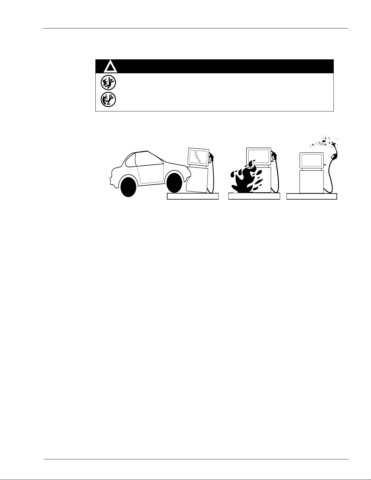
WARNING
Spilled fuels, accidents involving pumps/dispensers, or uncontrolled fuel flow create a
serious hazard.
Fire or explosion may result, causing serious injury or death.
Follow established emergency procedures.
DEF is non-flammable. However it can create a slip hazard. Clean up spills promptly.
Collision of a Vehicle with Unit Fire at Island Fuel Spill
MDE-4363F Atlas™ Fuel Systems Owner’s Manual · September 2011 Page 5
Page 10

Important Safety Information
This page is intentionally left blank.
Page 6 MDE-4363F Atlas™ Fuel Systems Owner’s Manual · September 2011
Page 11
Pump/Dispenser Components The Atlas Fuel System
3 – The Atlas Fuel System
Pump/Dispenser Components
This section provides figures that show the internal and external components of pumps and
provides information about these components. Refer this section as you perform the
procedures in this manual.
Atlas Pump/Dispenser
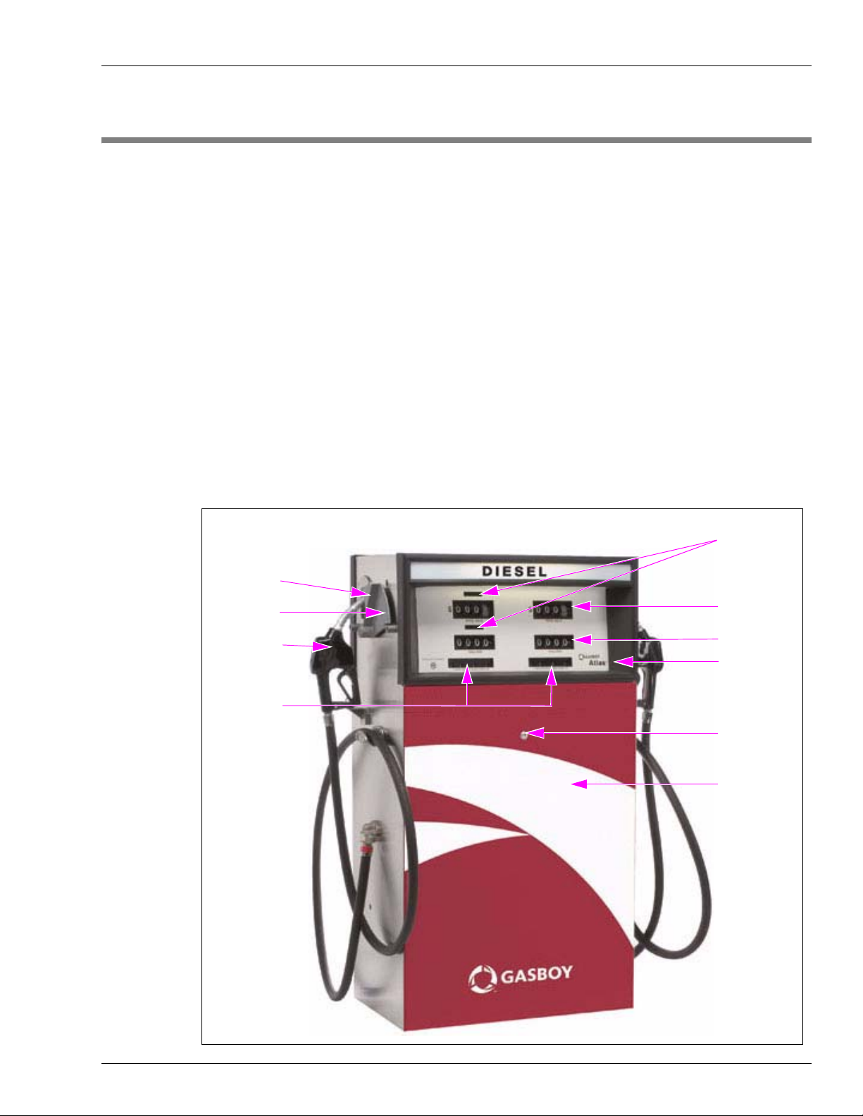
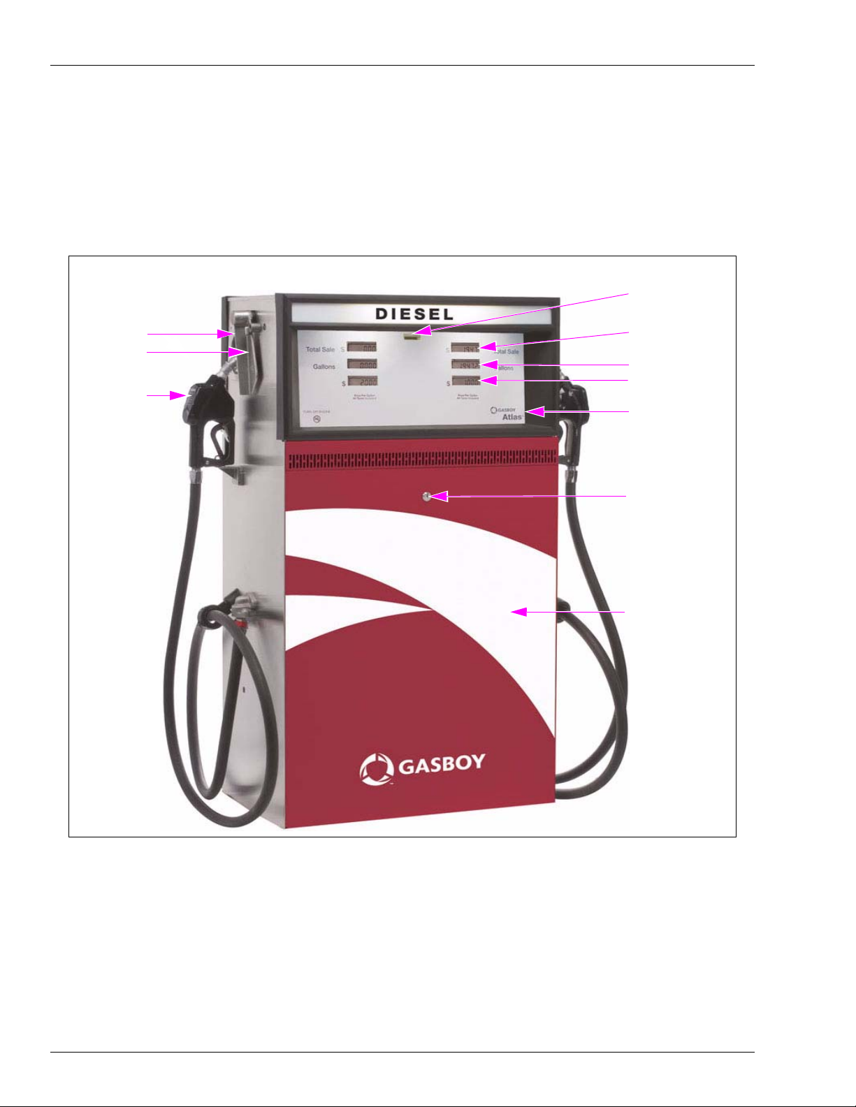
The external components of a Gasboy® Atlas pump/dispenser (Mechanical Retail Unit) are
shown in Figure 3-1. Mechanical units have mechanical digital type displays as opposed to
electronic digital type displays. In units that are Commercial instead of Retail, the external
components are almost the same with the exception that there are no cost displays, Price per
Unit (PPU) and the main display showing only the total fuel pumped.
Figure 3-1: Atlas Mechanical Retail Unit
Mechanical Retail Unit
Boot Area
Control Lever
Nozzle and
Pump Handle
PPU Display
Totalizers
Cost Display
Gallon Display
Gasboy Atlas
Logo
Door Lock
Access Door
MDE-4363F Atlas™ Fuel Systems Owner’s Manual · September 2011 Page 7
Page 12
The Atlas Fuel System Pump/Dispenser Components
The external components of a Gasboy Atlas pump/dispenser (Electronic Retail Unit) are
shown in Figure 3-2. Electronic units have digital displays as opposed to mechanical displays.
In units that are Electronic Commercial instead of Retail, the external components are almost
the same with the exception that there are only totalizers, PPU, and the main display showing
the gallons pumped.
Figure 3-2: Atlas Electronic Retail Unit
Electronic Retail Unit
Electro-mechanical
Totalizer
Boot Area
Control Lever
Nozzle and
Pump Handle
Digital Main
Display
Gallons Display
PPU
Gasboy Atlas Logo
Door Lock
Access Door
Page 8 MDE-4363F Atlas™ Fuel Systems Owner’s Manual · September 2011
Page 13
Pump/Dispenser Components The Atlas Fuel System
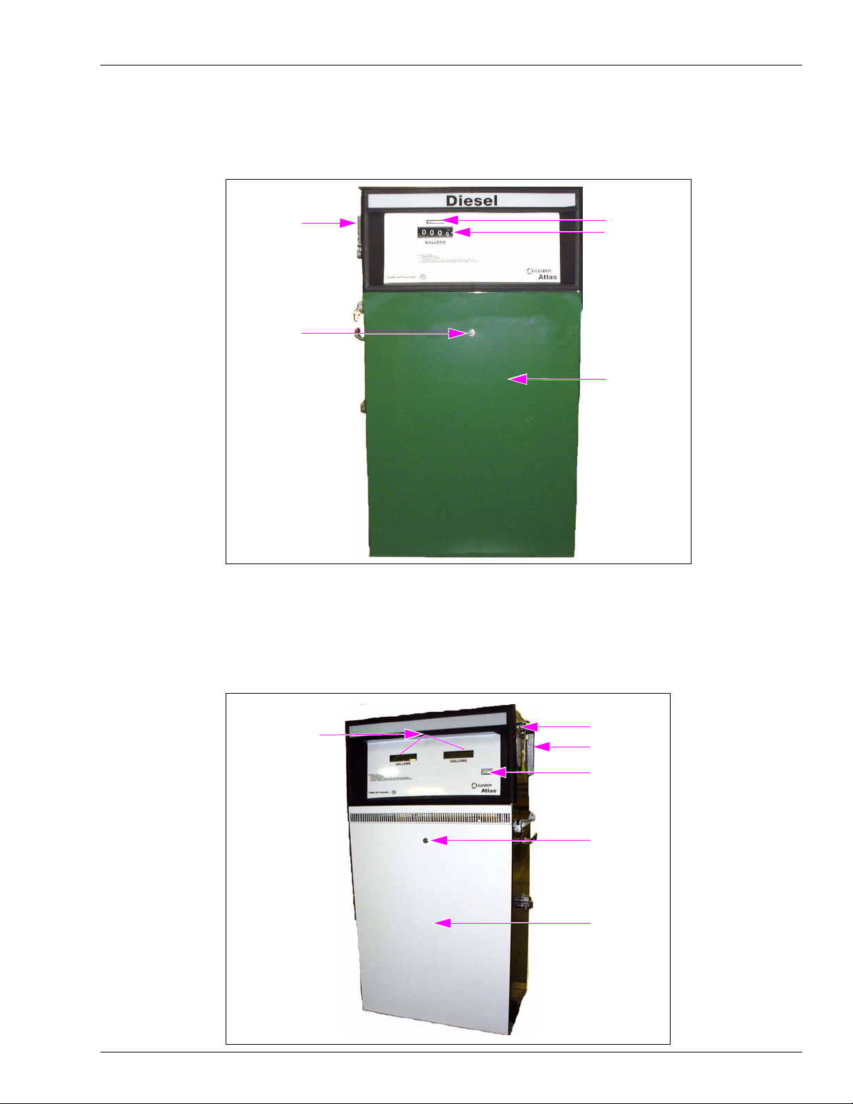
Commercial Mechanical - 9100
Figure 3-3: Commercial Mechanical - 9100
Control Lever
and Boot Area
Door Lock
Commercial Electronic - 9800
Totalizer
Volume Display
Access Door
Figure 3-4: Commercial Electronic - 9800
Volume Display
MDE-4363F Atlas™ Fuel Systems Owner’s Manual · September 2011 Page 9
Boot Area
Control Lever
Sensor
Door Lock
Access Door
Page 14
The Atlas Fuel System Pump/Dispenser Components
General Description - 9800 (Except 9820)
The Gasboy Atlas dispensing units are UL-listed and are available in a self-contained (suction
pump) package or in a remote-controlled (dispenser) package. Both packages offer varieties of
models which are available as single hose outlets or dual hose outlets (with single or dual
product capability). The self-contained models are available in standard flow (SF) models up
to 15 GPM (56 LPM/12 IGPM); high flow (HF) models up to 22 GPM (83 LPM/18 IGPM);
single-hose super high flow (SHF) models up to 40 GPM (151 LPM/33 IGPM); single-hose
ultra high flow (UHF) models up to 50 GPM (189 LPM/42 IGPM). The rate of delivery for the
remote-controlled packages will vary according to the size of the submersible pump. The
delivery rate of both packages will also vary depending on the installation conditions and
added accessories.
Visual identification can be quickly made between Commercial and Retail pumps/dispensers.
Commercial pumps/dispensers have displays only for gallons/liters on a side(s), when Retail
has displays for both gallons/liters and cost per gallon/liter.
The Atlas units can either have Side Load or Front Load nozzle configuration. The Atlas
pump/dispenser offers the following features.
Models Suction Pumps Remote Dispensers Features
SF Mechanical Commercial
SF Electronic Commercial
SF Mechanical Retail 8752K, 8752KTW1, 8752KTW2 8752KX, 8752KXTW1, 8752KXTW2
SF Electronic Retail 8852K, 8852KTW1, 8852KTW2 8852KX, 8852KXT W1, 8852KXTW2
HF Mechanical Commercial 9153K, 9153KTW2 9153KX, 9153KXTW2 • Inlet: 1-1/2” NPT female threads
HF Electronic Commercial 9853K, 9853KTW2 9853KX, 9853KXTW2
HF Mechanical Retail 8753K, 8753KTW2 8753KX, 8753KXTW2
HF Electronic Retail 8853K, 8853KTW2 8853KX, 8853KXTW2
SHF Mechanical Commercial 9140K 9140KX • Inlet: 2” NPT female threads
SHF Electronic Commercial 9840K 9840KX
UHF Electronic Commercial 9850K 9850KX, 9850KXTW2 • Inlet: 2” NPT female threads
SF Electronic Commercial
E85 Unit
DEF Dispenser 9862KX • Bottom Inlet: 1” BSPP female
9152K, 9152KTW1, 9152KTW2
9852K, 9852KTW1, 9852KTW2
9152KX, 9152KXTW1, 9152KXTW2
9852KX, 9852KXTW1, 9852KXTW2
9872KX, 9872KXTW1 • Inlet: 1-1/2” NPT female threads
• Inlet: 1-1/2” NPT female threads
• Discharge: 1” NPT female
threads (can be reduced to 3/4”
with bushing)
• Motor: (self-contained) 1 HP
continuous duty
• Discharge: 1” NPT female
threads
• Motor: (self-contained) 1 HP
continuous duty
• Discharge: 1” NPT female
threads
• Motor: (self-contained) (2) 1 HP
continuous duty
• Discharge: 1” NPT female
threads
• Motor: (self-contained) 1-1/2 HP
continuous duty
• Discharge: 3/4” NPT female
threads
threads
• Side Inlet: 1” BSPP male
threads
• Discharge: 1” BSPP male
threads
Page 10 MDE-4363F Atlas™ Fuel Systems Owner’s Manual · September 2011
Page 15
General Description of 9100K The Atlas Fuel System
General Description of 9100K
The Gasboy Series 9100K dispensing units are UL-listed and are available in a self-contained
(suction pump) package or in a remote-controlled (dispenser) package. Both packages offer
varieties of models which are available as single hose outlets or dual hose outlets (with single
or dual product capability). The self-contained models are available in standard speed, up to
56 LPM/15 GPM; in high speed, up to 83 LPM/22 GPM; or in a single hose model with high
capacity speed, up to 99 LPM/26 GPM. The rate of delivery for the remote-controlled
packages will vary according to the size of the submersible pump. The delivery rate of both
packages will also vary depending on the installation conditions and added accessories.
All models of the Series 9100K offer mechanical non-computers complete with electric resets.
Mechanical pump registers show the total volume for a delivery. All non-computers will read
up to 999.9 gallons or liters.
Common Functions
This subsection provides instructions for common functions on the Gasboy Atlas
pumps/dispensers.
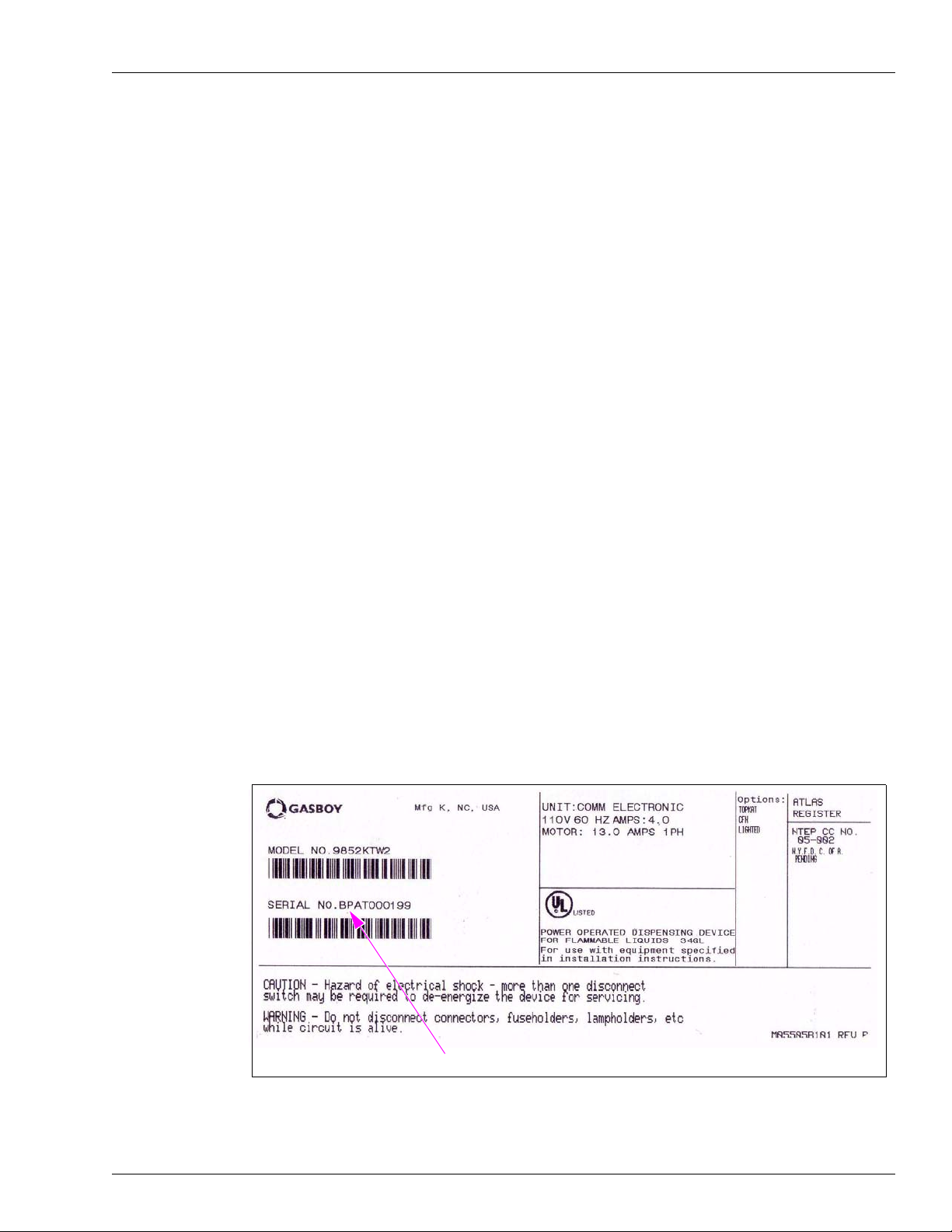
Understanding Date Codes
A two letter date code is stamped on the serial number plate before the serial number. This
code shows the month and year of manufacture. To determine the age of the equipment for
warranty purposes, refer to the date code.
Figure 3-5: Serial Number Plate
Serial Number
MDE-4363F Atlas™ Fuel Systems Owner’s Manual · September 2011 Page 11
Page 16
The Atlas Fuel System Common Functions
For example, a serial number plate stamped “BP AT0001 99” contains the following
information:
• Date code [BP]—This unit was manufactured in B=February P=2005.
• Serial Number [AT000199]
To determine the date code on a Gasboy pump or dispenser, refer to the following tables.
Month Codes
A = January E = May J = September
B = February F = June K = October
C = March G = July L = November
D = April H = August M = December
Year Codes
P = 2005 U = 2009
R = 2006 W = 2010
S = 2007 X = 2011
T = 2008 Y = 2012
Pump Totals (9100 Series)
Pump totals can be read from the totalizers. At the close of each day’s business, the total can
be read from the unit and subtracted from the day before to obtain the total for that day. If the
unit is in use 24 hours a day, it is advisable to take the readings in the morning also, so as to
monitor the night usage.
Figure 3-6: Pump Totals - 9120
Totalizer
Page 12 MDE-4363F Atlas™ Fuel Systems Owner’s Manual · September 2011
Page 17
Common Functions The Atlas Fuel System
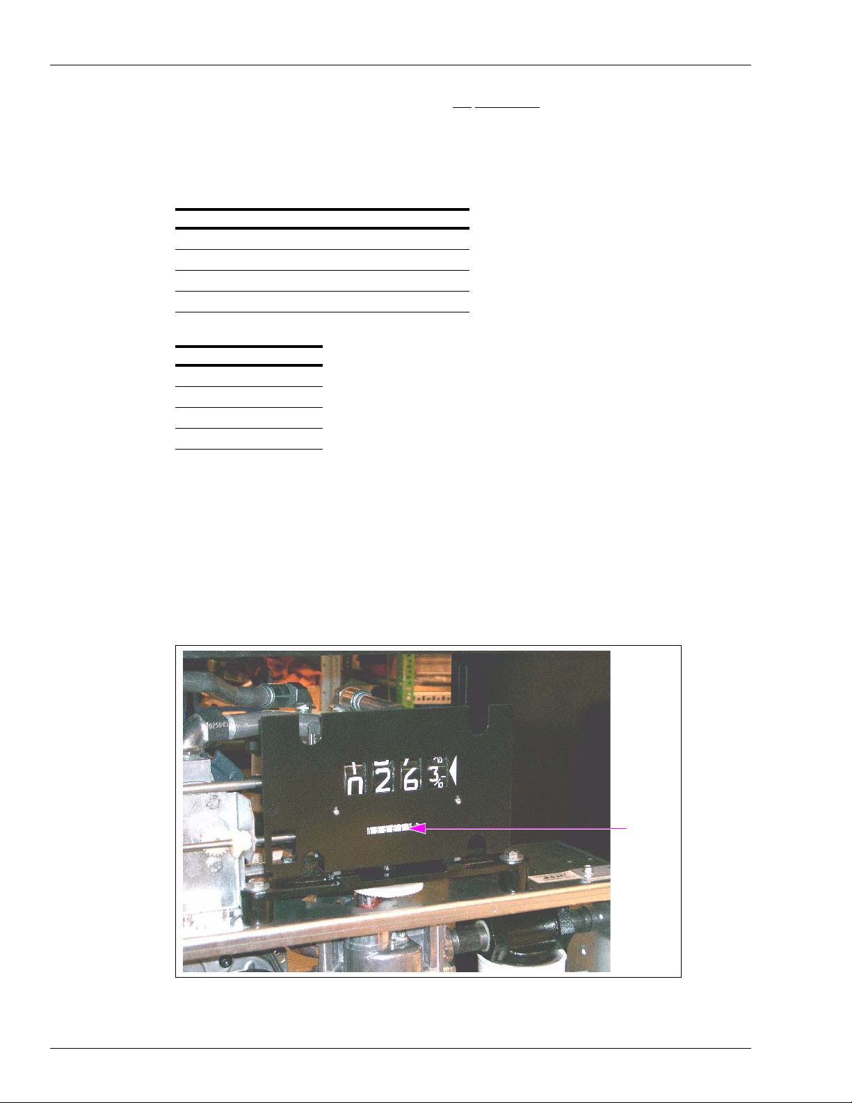
Commercial Electronic (Series 9800 Only)
Figure 3-7: Commercial Electronic Totals - 9800
Commercial Electronic
Electrical Mechanical
Totalizer
ATC Switch
Note: For all Series 9800 except 9820.
Totalizer Activate Area
The Atlas stores a running quantity total for each pump side. These electronic totalizers work
independent of the optional electrical mechanical totalizers that may be installed and are
shown as whole gallons (liters) on the displays (decimal point is shown, although it is
disregarded). The totalizer data is stored in battery-backed memory. The Atlas is supplied with
an actuator (shown in the above illustration) which allows you to view and reset electronic
totalizers.
To view pump totalizers, ensure that the pump handles are off; and no transaction is in
progress. Locate the actuator area (where the Gasboy dial face logo is located) that is on the
same pump side as the serial number tag. Touch the actuator area with the actuator as shown.
The totalizer data for each pump side will be displayed for 10 seconds. If more time is
required, touch the actuator to the actuator area for an additional 10 second period. To reset the
electronic totalizers, refer to “Electronic Component Access (Series 9800 Only, Except 9820
Series)” on page 19.
• Turn off the 9800K power switch.
• Close JP7 (or SW1-7 for older CPU boards) on the CPU PCB. Hold the actuator against
the totalizer bracket and turn the power switch ON. The displays must change to all
zeroes.
• Remove the actuator and open the switch JP7 (or SW1-7).
Note: Returning switch 1-7 to the open position prevents the totalizers from being reset the
next time the actuator is used to read them.
MDE-4363F Atlas™ Fuel Systems Owner’s Manual · September 2011 Page 13
Page 18

The Atlas Fuel System Mechanical Totalizers for 9850 Only
Mechanical Totalizers for 9850 Only
An optional mechanical totalizer for each side is available for 9850 models only . Each totalizer
has:
• Eight digits
• Seven whole gallons
• One tenth-gallon column
• Eight whole digits for liters
The mechanical totalizers are located below each nozzle hook (see Figure 3-8).
Figure 3-8: Mechanical Totals for 9850 Series - 1
Nozzle Hook
Figure 3-9: Mechanical Totals for 9850 Series - 2
Totalizer
Totalizer Cable
Totalizer Unit
Page 14 MDE-4363F Atlas™ Fuel Systems Owner’s Manual · September 2011
Page 19

Site Preparation The Atlas Fuel System
Site Preparation
To ensure safety and long-term reliability of your equipment, ensure that your units are
installed by a knowledgeable ASC. When your units are installed, ensure that the installer
considers the guidelines in the following section.
Important Requirements for E85 Units
The following equipment and materials are required to properly install E85 units:
UL-listed E85 Hose (Q13486)
• Veyance
• Veyance Flexsteel Futura for E25
Note: Extended Reach hoses are not available for the E85 applications.
UL-listed E85 Nozzle (M11298)
OPW 21GE
Note: Approved for use with the E85 dispensers, as required under UL 87A.
SM
Flexsteel® Futura™ Ethan-All for E85
UL-listed E85 Swivel (N23748-04)
OPW 241 TPS-0492
Note: Approved for use with E85 dispensers, as required under UL 87A.
UL-listed E85 Shear Valve (T19695-23)
OPW 10P-0152E85
Note: Approved for use with E85 dispensers, as required under UL 87A.
UL-listed E85 Breakaway (N23010-10)
OPW 66V-0492
Note: Approved for use with E85 dispensers, as required under UL 87A.
Filter
Use only filters specifically marked for use with E85.
UL-listed Pipe Sealant
Use only UL-listed TPS PTFE Pipe Sealant manufactured by SAF-T-LOC International Corp.
UL-listed Teflon
®
Tape
Use only UL-listed Taega Technologies Inc. Teflon tape.
Note: Teflon tape must be used only at the inlet pipe connection.
IMPORTANT INFORMATION
For E85 Front Load units, side B is the side with the Junction Box. For nozzle boot
positioning for the different models, refer to Atlas Foundation Diagrams section in
MDE-4331 Atlas Fuel Systems Installation Manual.
MDE-4363F Atlas™ Fuel Systems Owner’s Manual · September 2011 Page 15
Page 20

The Atlas Fuel System Site Preparation
Important Considerations for DEF Dispensers
CAUTION
Applicable during Installation and Operation of the Dispenser: DEF freezes at appro ximately
11 °F (-11.5 °C). Power to the dispenser and heater must always remain ON in cold weather. If
power is lost and the temperature drops below this point within the DEF cabinet, the system must
be inspected for freeze damage before restart. For sites that experience occasional power losses
or for sites that are located in very cold climates, it is recommended that a backup power generator
be used to maintain constant power to the dispenser. Do not use any additives to lower the freezing
point of DEF. Additives of any type must not be used in DEF. Freezing can result in damage or
inoperative hose breakaways, fluid lines or components, valves, nozzles and meters.
Prolonged storage at temperatures above 77 °F (25 °C) can impair the quality of DEF and reduce
its shelf life.
CAUTION
DEF is mildly corrosive. It can corrode components that are made from incompatible material(s)
and reduce their integrity. The use of incompatible material(s) may lead to leaks and spills, and can
contaminate and degrade the DEF. When dispensing DEF, verify with the manufacturer if the
material of all plumbing components are compatible with the DEF being dispensed.
CAUTION
Do not use Prover Cans meant for engine fuel with DEF or vice versa. Use stainless steel Prover
Cans for DEF. DEF and engine fuel must not be mixed with each other or be contaminated by each
other. Else, damage to a vehicle’s engine or pollution control devices could occur. DEF crystallizes
as its water base evaporates. Pouring out liquid will not guarantee that no corrosive DEF remains in
the Prover Can. DEF must not be contaminated with Diesel fuel, contaminants, or other fluids or
materials. Such contamination can cause serious damage to vehicle catalytic converters.
• Conventional fluid handling precautions are also applicable to DEF.
• Avoid contact with eyes, skin, and clothing. Ensure that eyewash stations and safety
showers are close to the work location.
• DEF is mildly corrosive and non-flammable.
• Clean the DEF spill with water and dry the area with clean rags, especially areas that
contain metallic parts. Spilt DEF can be slippery and will corrode certain types of metallic
parts. Wear eye protection and rubber gloves during any cleanup activity.
• DEF is heavier than gasoline. Be aware that prover cans, containers filled with DEF, and
so on will be considerably heavier than gasoline.
Page 16 MDE-4363F Atlas™ Fuel Systems Owner’s Manual · September 2011
Page 21

Site Preparation The Atlas Fuel System
Guidelines in Atlas Fuel Systems Documentation and Other Codes
The following manuals provide guidelines for installing Atlas Fuel Systems
pumps/dispensers:
• MDE-4331 Atlas Fuel Systems Installation Manual
• MDE-4333 Atlas Fuel Systems Site Prep Manual
• FE-356 Atlas Pump and Dispenser Field Wiring
• FE-357 Atlas Pump Retail/Commercial Field Wiring
• FE-361 Atlas Master & Satellite Field Wiring Diagram
Ensure that the installer follows the instructions in the above listed manuals and adheres to all
applicable local, state, and national codes.
General Guidelines
Ensure that the installer, at a minimum, performs the following tasks:
• Attaches the hose breakaways.
• Follows all manufacturer installation instructions for devices attached to the dispenser,
such as hoses, nozzles, and shear valves.
• Installs a line leak detection system for all dispensers (The system must comply with all
local and state codes).
• Uses only UL-listed or approved attachments with the pump/dispenser.
• Installs shear valves for all dispensers and certain above ground tank pump applications
properly.
• Follows all codes.
• Bolts units to the island properly .
• Tests hoses for conductivity before use as per the manufacturer’s instructions.
• Uses appropriate safety signs as outlined in the manuals listed in “Guidelines in Atlas Fuel
Systems Documentation and Other Codes”.
• Uses isolation relays for dispensers (required by National Electrical Codes).
• Uses the recommended hose lengths for each unit unless you are using hose retrievers.
Note: This is not a complete list. For other requirements, refer to “Guidelines in Atlas Fuel
Systems Documentation and Other Codes”.
MDE-4363F Atlas™ Fuel Systems Owner’s Manual · September 2011 Page 17
Page 22
The Atlas Fuel System Site Preparation
Hoses
Hoses must be UL approved and conductive from end-to-end. To determine the hose length,
refer to “Determining Hose Length”.
Note: When determining the hose length, the effect of adding breakaways adds significantly to
the actual hose length.
WARNING
Hoses of excessive length may create a trip hazard.
Serious injury could occur as a result of tripping over an excessively long hose.
Do not use excessive length hoses. Also ensure that hose retrievers are installed
and are in good operating condition.
Do not install soft-wall hoses, they commonly cause a small sale to indicate when the unit is
activated and the nozzle is closed.
Determining Hose Length
To determine the correct hose length for various types of hoses, refer to the following table.
Type Length
Standard hardwall 5/8 or 3/4 ID (without breakaway) 10 feet, 6 inches
Standard hardwall 5/8 or 3/4 ID (with breakaway) 9 feet, 6 inches
Standard breakaway whip hose 1 foot, 0 inches
Install Warning Labels and Signs for Customers
Install warning labels and signs to ensure that customers are warned of potential safety
hazards. Ensure that the warning labels and the signs are readily visible. At a minimum, install
the following signs:
• Turn off the vehicle before fueling.
• No smoking; do not use matches or lighters nearby.
• Use only non-breakable, approved containers for storing fuel; ensure that the container is
metal and identified properly for fuel storage.
• Static electricity hazards during fueling.
Promptly replace any missing, incomplete, or illegible labels or operating instructions.
WARNING
Static electricity can cause an explosion.
Static electricity, including an electrostatic charge on your body, can cause a spark
sufficient to ignite fuels and their vapors.
After getting out of a vehicle, touch the metal of your vehicle to discharge any
electrostatic charge before you approach the dispenser island.
Page 18 MDE-4363F Atlas™ Fuel Systems Owner’s Manual · September 2011
Page 23
Operating Pumps/Dispensers The Atlas Fuel System
Operating Pumps/Dispensers
This section describes the operation of the pump/remote dispenser. It provides information on
how to:
• Access the electronic components
• Set the standalone switch
If you are using a point of sale device, refer to the manufacturer instructions.
Electronic Component Access (Series 9800 Only, Except 9820 Series)
This section describes the operation of the pump/remote dispenser. It provides information on
how to:
• Access the electronic components
• Set the internal switches
• Set the optional battery back-up power supply
• View and reset the electronic totalizers using the actuator
• Operate both pumps and remote dispensers
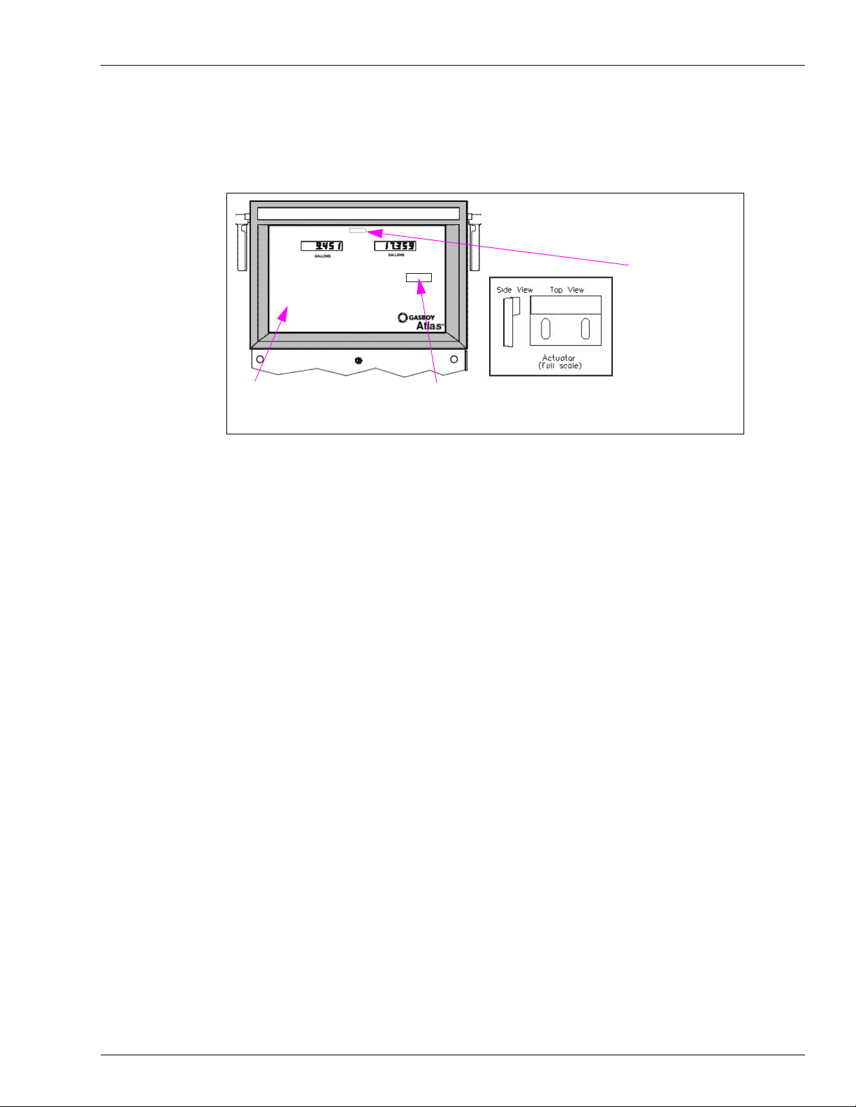
1 Unlock and remove the front panel (see Figure 3-10).
Figure 3-10: Front Panel of 9800 Series
TURN OFF ENGINE
Atlas
Unlock
MDE-4363F Atlas™ Fuel Systems Owner’s Manual · September 2011 Page 19
Page 24
The Atlas Fuel System CPU Switch Settings (Series 9800 Only Including DEF 9862 Units)
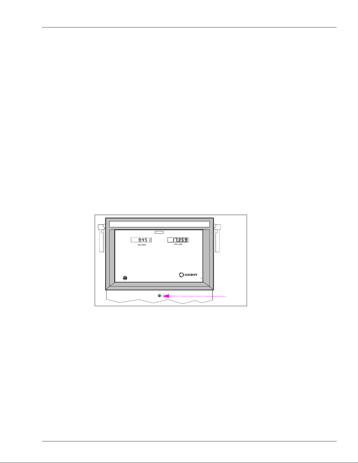
2 Remove the two bolts securing the bezel assembly and remove bezel.
3 Remove the two bolts securing the display panel and pivot display panel down.
Figure 3-11: Display Panel
Note: Unit will swing forward and down
after screws are removed.
Loosen and remove
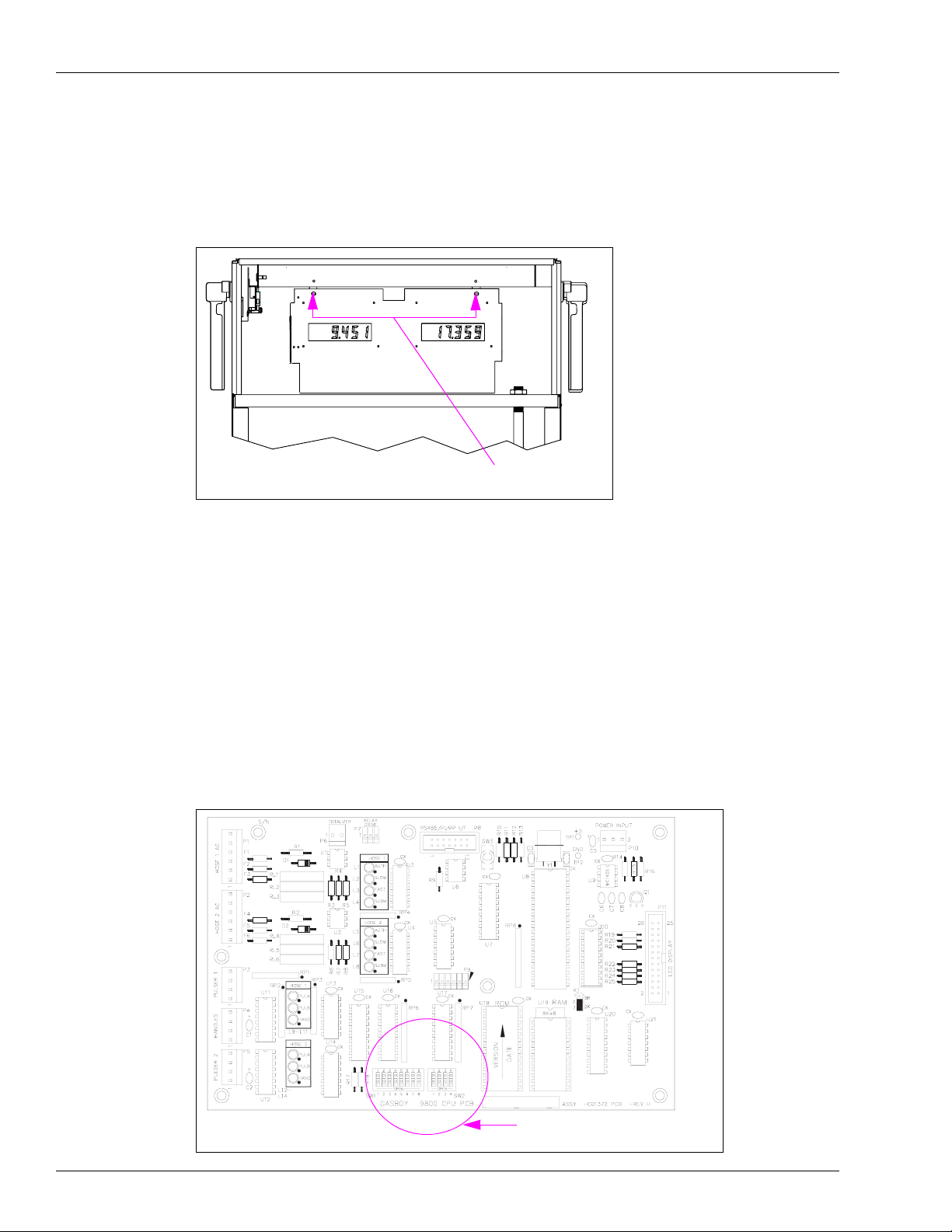
CPU Switch Settings (Series 9800 Only Including DEF 9862 Units)
The Series 9800 can be configured for various operating conditions using the switches located
on the CPU PCB. Inspect these switches and change their settings, if required. Switch settings
must be changed with the power switch OFF. CPU PCB reads the new settings when the
power is turned ON again.
Note: Older Series 9800 CPU Diagram (board C06394, M05318, M05346).
Figure 3-12: Old CPU Board for 9800 Series
CPU PCB Switches SW1 and SW2
Page 20 MDE-4363F Atlas™ Fuel Systems Owner’s Manual · September 2011
Page 25

CPU Switch Settings (Series 9800 Only Including DEF 9862 Units) The Atlas Fuel System
Figure 3-13: New CPU Board for 9800 Series
Serial Peripheral I/F Port
CPU Switch S1
Newer Series 9800 CPU Board (M06333A)
CPU Jumpers
Note: In the following tables, SW1 refers to switch banks in older series 9800 boards. Jumpers
JP1-JP9 are used for new CPU boards (M06333A). Also, in new CPU boards, Closed
indicates that the CPU board is jumpered and Open indicates the absence of a jumper.
MDE-4363F Atlas™ Fuel Systems Owner’s Manual · September 2011 Page 21
Page 26

The Atlas Fuel System CPU Switch Settings (Series 9800 Only Including DEF 9862 Units)
CPU Jumpers (or SW1 for Older CPU Boards)
SW1-1 or JP1: Baud Rate
This switch is set to reflect the communications rate of the Gasboy RS-485 pump loop. It is:
• Open for 9600 baud
• Closed for 1200 baud
The Gasboy CFN system and TopKAT
Baud Rate SW1-1/JP1 Fuel System
9600 Open CFN
TopKAT top-mount
TopKAT electronic
1200 Closed None currently supported
™
communicate at 9600 baud.
SW1-2 or JP2: Mode
If the Series 9800 is controlled by a Gasboy CFN, TopKAT top-mount, or TopKAT electronic
fuel management system, the switch must open (on-line mode). If the Series 9800 is controlled
by a Gasboy Series 1000 or TopKAT mechanical system, or controlled by any non-Gasboy
system, or not controlled by any fuel management system at all, the switch must be closed
(standalone mode).
Note: The 9800K is shipped in the standalone mode unless it has the TopKAT top-mount
option. With the TopKAT top-mount option, the unit is shipped in on-line mode.
Mode SW1-2/JP2 Fuel System
On-line Open CFN
Standalone Closed Series 1000
TopKAT top-mount
TopKAT electronic
TopKAT Mechanical
All non-Gasboy systems
No fuel system
SW1-3, SW1-4 or JP3, JP4: Delay Time
These two switches set the delay time used by leak detectors in submersible pump
applications. The delay time is the period between the activation of the submersible pump and
the activation of the slow flow valve. This time must be set according to the type of leak
detector installed on the submersible pump to allow a normal leak test for each transaction.
The delay time must be set to zero seconds for suction pumps.
Delay Time SW1-3/JP3 SW1-4/JP4
0 seconds Closed Closed
4 seconds Closed Open
5 seconds Open Closed
6 seconds Open Open
Page 22 MDE-4363F Atlas™ Fuel Systems Owner’s Manual · September 2011
Page 27

CPU Switch Settings (Series 9800 Only Including DEF 9862 Units) The Atlas Fuel System
SW1-5 or JP5: Hose Pressurization
If the Series 9800 program is configured for US Gallons, this dip switch setting is ignored and
the program will always act as if it is enabled. If the Series 9800 program is configured for
Liters or Imperial Gallons, this switch will control whether pump pressurization is enabled. If
a pump has been idle for more than ten minutes or this is the first use after start-up, a
maximum of 0.02 units of unrecorded volume will be pumped into the pump hydraulics during
the pump’s segment test.
Pressurization SW1-5/JP5
Enable Closed
Disable Open
SW1-6 or JP6: Authorization
This switch allows activation of the Series 9800 from some types of fuel management systems.
When the switch is closed, a 115 VAC (230 VAC international) signal must be present on the
AUTH/Control Feed line for pump activation to occur (required setting for Series 1000,
TopKAT mechanical, and all non-Gasboy systems). When open, the Series 9800 ignores the
AUTH/Control Feed line (normal setting for CFN, T opKAT top-mount, T opKAT electronic, or
no fuel system).
Authorization SW1-6/JP6 Fuel System
Yes Closed Series 1000
TopKAT mechanical
All Non-Gasboy systems
No Open CFN
TopKAT top-mount
TopKAT electronic
No fuel system
JP7 (or SW1-7): Electronic Totalizers
This switch must be open for normal operation. When closed, this switch enables the reset of
the electronic totalizers. For more information, refer to “Commercial Electronic (Series 9800
Only)” on page 13.
Totalizers JP7 (or SW1-7)
Reset Closed
Normal Open
MDE-4363F Atlas™ Fuel Systems Owner’s Manual · September 2011 Page 23
Page 28

The Atlas Fuel System CPU Switch Settings (Series 9800 Only Including DEF 9862 Units)
JP8 (or SW1-8): RS-485 Emergency Pump Stop Detection
This switch must be set to open (default) to enable RS-485 pump stop detection. The Gasboy
RS-485 pump stop switch, when activated, places a serial break character on the RS-485 lines.
When SW1-8 or JP8 is open, this breaker character triggers the termination of the sale(s)
immediately, if a transaction(s) is in progress.
This switch must be set to closed (in TopKAT or CFN Plus system Communication) to disable
RS-485 pump stop detection. This resolves the issue associated with the false break characters
being detected that may be introduced when 485 half-duplex communication is used.
ESTOP Detection SW1-8/JP8
Enabled Open
Disabled Closed
JP9 only exists on new boards and is not used.
SW2 (For Older and Newer CPU Boards)
Notes:1) Four-position switch bank only exists in older boards C06394, M05318, M05346 for
the Series 9800.
2) Ten-position switch bank only exists on newer Series 9800 CPU Boards M06333A.
For older CPU Board, this four-position switch pack serves a dual purpose:
• As an address setting when communicating using the Gasboy RS-485 PAC Data Protocol
(CFN or TopKAT), or
• When using a pulse output board, as a pulser output rate selector for pulser data to be sent
to a fuel management system other than a Gasboy CFN or TopKAT.
For newer CPU Board, this ten-position bank serves a dual purpose:
• As an address setting for the Gasboy RS-485 PAC Data Protocol (CFN or TopKAT), Unit
of Measure, BDM Enable, Software Load Enable, and Electro-mechanical Totalizer
Enable; or
• As a pulse output rate selector when pulser data is sent to a fuel management system other
than Gasboy CFN or TopKAT , Unit of Measure, BDM Enable, Software Load Enable, and
Electro-mechanical Totalizer Enable.
Address Switches
A unique address identifier must be set when the Series 9800 is connected to the Gasboy
RS-485 pump loop via the 9800 RS-485 I/F PCB. There are 16 possible address combinations.
Addressing must start at 1 and continue sequentially through 16. The physical wiring order
does not have to correspond with the address order, that is, the first unit on the RS-485 loop
does not have to be address 1. With the TopKAT top-mounted option, the address must be set
to 1. The following chart gives the switch settings and address selections.
Address SW2-1 SW2-2 SW2-3 SW2-4
1 Closed Closed Closed Closed
2 Open Closed Closed Closed
3 Closed Open Closed Closed
4 Open Open Closed Closed
5 Closed Closed Open Closed
Page 24 MDE-4363F Atlas™ Fuel Systems Owner’s Manual · September 2011
Page 29

CPU Switch Settings (Series 9800 Only Including DEF 9862 Units) The Atlas Fuel System
Address SW2-1 SW2-2 SW2-3 SW2-4
6 Open Closed Open Closed
7 Closed Open Open Closed
8 Open Open Open Closed
9 Closed Closed Closed Open
10 Open Closed Closed Open
11 Closed Open Closed Open
12 Open Open Closed Open
13 Closed Closed Open Open
14 Open Closed Open Open
15 Closed Open Open Open
16 Open Open Open Open
Pulser Output Rate Switches
When the Series 9800 is connected to external control equipment other than a Gasboy CFN,
Gasboy TopKAT top-mount or Gasboy TopKAT electronic (standalone), the pulser signals are
sent out via the 9800 Pump I/F PCB. The pulse rate required by the monitoring equipment can
be configured by setting the switches as shown in the following chart. The pulse rate
represents pulses per gallon (PPG for US Gallons and Imperial Gallons) or pulses per liter
(PPL, most international). For US Gallons or Imperial Gallons configurations, the pulse rate
can be up to 100 PPG for the 9850 and 500 PPG for all others models. For liters
configurations, the pulse rate can be up to 10 PPL for the 9840 and 9850, and 100 PPL for all
other models. For Imperial Gallons configurations, the pulse rate can be 100 PPG for the 9850
and 500 PPG for all other models. This switch must be sealed by a Weights and Measures
paper seal if the Series 9800 unit is used for the resale of product.
Leading zeroes are always suppressed in the hundreds and tens positions to the left of the
decimal point. When in standalone mode, positions to the right of the decimal point are
displayed based on the pulse rate selected as shown in the following table.
Pulse Rate SW2-1 SW2-2 SW2-3
1 Closed Closed Closed
10 Open Closed Closed
100 Closed Open Closed
250 Open Open Closed
500 Closed Closed Open
None Closed Open Open
None Open Open Open
Note: For the last two switch settings, no pulse will be sent to
the Fuel Management System.
Pulse Rate 9800/9840 Display Layout 9850 Display Layout
1:1 XXX. XXXX.
10:1 XXX.X XXXX.X
100:1 XXX.XX XXXX.XX
250:1 XXX.XXX XXXX.XX
500:1 XXX.XXX XXXX.XX
MDE-4363F Atlas™ Fuel Systems Owner’s Manual · September 2011 Page 25
Page 30

The Atlas Fuel System CPU Switch Settings (Series 9800 Only Including DEF 9862 Units)
Time-out Switch
When the Series 9800 is in standalone mode, it will turn off an active hose if it does not detect
pulses for four minutes, 15 seconds. This time-out feature can be disabled by setting switch
SW2-4 to OPEN.
Timeout SW2-4
Enabled Closed
Disabled Open
SW2-5 and SW2-6: Unit of Measure Setting (New M06333KXXXX CPU Only)
These two switches select the Unit of Measurement: US Gallons, Imperial Gallons, and Liters.
For information, refer to the following table.
Unit of Measure SW2-5 SW2-6
US Gallons Closed Closed
Liters Open Closed
Imperial Gallons Closed Open
N/A Open Open
SW2-7: Electro-Mechanical Totalizer Enable (New M06333KXXXX CPU Only)
The K model pumps/dispensers have an option to use Electro-mechanica l Totalizers. If these
are installed, then this switch must be set to CLOSED for proper operation of the totalizers.
This switch does not affect the operation of the electronic totalizer or the mechanical totalizer.
EM Totalizer SW2-7
Enabled Closed
Disabled Open
SW2-8: BDM Enable (New M06333KXXXX CPU Only)
This switch must always be set to OPEN for normal operation.
SW2-9: Software Download Enable (New M06333KXXXX CPU Only)
This switch must be OPEN for normal operation. When this switch is closed, it enables
loading new M06333KXXXX CPU software.
Software Download Enable SW2-9
Enabled Closed
Disabled Open
SW2-10 (New M06333KXXXX CPU Only)
This switch is not used.
Page 26 MDE-4363F Atlas™ Fuel Systems Owner’s Manual · September 2011
Page 31

Battery Backup Power Supply for Series 9800 The Atlas Fuel System
Battery Backup Power Supply for Series 9800
Figure 3-14: 9800 Series Power Supply
P1 Connector
Series 9800 models can be equipped with an optional battery backup power supply. This
allows the last transaction data to be displayed for a minimum of 15 minutes. After the
batteries reach a certain low-voltage point, the power will automatically shut-off. If you have
to shut-off the battery power before the low-voltage point is reached, momentarily disconnect
and then re-connect the cable that plugs into P1 on the power supply.
The Atlas DEF 9862 cold and warm weather units do not use the battery on the power supply.
Information for ATC (Series 9800 Only)
By activating the magnet located at the opposite side of the totalizer, various items will appear
on the display.
1. Volume Display Displays uncompensated volume 0023.43
2. Probe Temperature Display Displays probe temperature in Celsius only 023.2
3. Flow Rate Display Displays Flow Rate (in LPM only) 189.2
4. Software Version Display Displays software version number 1.30
5. ATC Status Display Displays ATC Status 842.2
On the ATC Status Display, the rightmost digit (2) indicates whether the temperature
compression is enabled or not. If enabled, it shows which product is being dispensed.
• 0=temperature compensation enabled
• 1=product is gasoline and compensation enabled
• 2=product is diesel and compensation enabled.
Note: Not used in the Atlas DEF 9862 units.
MDE-4363F Atlas™ Fuel Systems Owner’s Manual · September 2011 Page 27
Page 32

The Atlas Fuel System Changing the Price for the Mechanical Retail Pump
On the ATC S tatus Display, the leftmost digits (842) are error indicators which are blank when
the corresponding error condition is not active. When any of the following digits are
displayed:
• 8=temperature probe fault is detected
• 4=pulser error occurred
• 2=exceptional reset was detected
Setting the DIP Switches (Found on Kraus ATC Boards)
DIP Switch Settings
Switch Number Switch Function Settings for 9800 Series
1 Product 1 ON=Diesel; OFF=Gasoline
2 Product 2 ON=Diesel; OFF=Gasoline
3 Not Used
4 9840K, 9852K, and 9853K ON=Liters; OFF=Gallons
5 Pulser Multiplier ON=9850; OFF=9852/9853
6 # of Probes ON=2, OFF=1
7 Pulser Adder ON=9840
8 ATC ON=ATC on; OFF=ATC off
Figure 3-15: Setting the DIP Switches
Commercial Electronic
Side B
ATC Switch Area
Changing the Price for the Mechanical Retail Pump
Atlas (Gallon unit of measure)
Temporary pricing must have already been entered into the unit as outlined in the purging
section to allow dispensing and calibration. Follow the procedures given below:
• Current production Atlas pumps/dispensers are pre-calibrated to US gallons and
programmed to default programming values.
Note: Calibration verification is still required.
Page 28 MDE-4363F Atlas™ Fuel Systems Owner’s Manual · September 2011
Page 33

Changing the Price for the Mechanical Retail Pump The Atlas Fuel System
• They may be operated and purged in normal mode after entering the prices (add pricing
programming information from service manu al or for mechanical units, from the
directions on the outside of the computer).
• Purging can be performed for units eventually to be converted to metric mode, when the
unit is in the gallon mode.
Figure 3-16: Mechanical Retail Pump PPU
Variator
Note: Directions for changing the price can be found on the outside of the variator cover.
Note: This section and the diagrams pertain to the mechanical models only.
1 Unlock and remove the front panel. Repeat this procedure for the other side.
2 The variator section of the computer register(s) is exposed to allow price changes. Slide the
variator cover of the computer register apart, to expose the price range arms.
MDE-4363F Atlas™ Fuel Systems Owner’s Manual · September 2011 Page 29
Page 34

The Atlas Fuel System Changing the Price for the Mechanical Retail Pump
3 There are three range arms located in the variator section. One sets the tenths of a cent
position, one sets the one cent position, and the last one sets the ten cents position. To change a
setting, grasp a range arm and raise it to clear the range arm locator, and relocate the range arm
to the required setting. Ensure that the range arm is totally bottomed on its setting. Repeat this
for all range arm settings, if required.
Figure 3-17: Location of Range Arms
Range Arm
Range Arm Locator
4
To change the money unit setting, locate the control lever which is located above the variator
section on the same level as the price display. There are three available positions: 0.00, 1.00,
and 2.00. Remove the cotter pin, grasp the lever, and raise it slightly to clear the position
locators. Position the lever to the required setting and release. Reinsert the cotter pin through
the lever and plate.
Note: If the lever does not move to the required position, rotate the right hand money wheel
until the lever is free to move.
Figure 3-18: Control Lever
If you have difficulty reaching the money shift lever when changing prices, remove the two
5
cap screws located over the tabs of the bezel assembly. Lift the bezel assembly upward and
remove it from the unit. When reattaching the bezel to the dispensing unit, ensure that the top
inner edge of the bezel assembly slides into the “U” shaped channel located on the upper edge
of the dispensing unit.
Page 30 MDE-4363F Atlas™ Fuel Systems Owner’s Manual · September 2011
Page 35

Programming 8800 Models The Atlas Fuel System
Programming 8800 Models
General Programming
Programming the unit is divided into three levels; Level 1, 2, and 3. Level 1 codes are
explained here. The default code for level 1 is 2222. This code can be changed for station
security, however losing the codes will require a master reset of the unit. Reprogramming
codes found in Level 1 are shown below:
• CC 1 Manual programming of PPU (unit pricing). Pricing can also be downloaded
through the Two-wire communication using the Point Of Sale (POS) device.
• CC 2 Sitting mode of operation as being stand alone (isolates sale control from the POS)
or Two-wire (unit control through the POS).
• CC 3 Programming Volume Allocation. This basically sets the maximum sale size in units
of measure (gallons for example).
• CC 4 Manual Blank and Five-Button Preset. This dual use code allows turning the
displays off manually or is used to activate different preset modes depending on the
options included with the unit.
• CC 5 Test Programmable Customer Preset. This code is used to initiate testing for the 5
Button Preset option, if used.
• CC 6 Memory Clear. This code is useful only to clear a unit displaying an Error Code (EC)
31 Totals Data Error) or EC 35 Configuration Data Error.
• CC 7 Setting Totals Input. This code allows setting of non zero totals. It is useful for new
installs or service (old dispensers are replaced or receive certain types of service), when
the station does not want to restart totals for its dispensers at zero. It can only be
performed after performing a master reset, CC7, or for new units.
• CC 8 display Pump Controller Firmware Version.
MDE-4363F Atlas™ Fuel Systems Owner’s Manual · September 2011 Page 31
Page 36

The Atlas Fuel System Programming 8800 Models
x
#
Programming the 8800 Series Retail Electronic Units
This section describes the level 1 programming procedures and considerations for the 8800
series.
Figure 3-19: Programming of 8800 Series Retail Electronic Units
Conversion Factor
US Gallons
Imperial Gallons
Liters
1012 Pulses per Gallon
Memory Error
ROM Error
RAM Error
Sides
Single-sided
Dual-sided
Code
0
1
2
3
Code
1
2
Code
1
2
Level 1 Programming and Data Access
Figure 3-20: Manager’s Keypad
Pump Controller Software Version
The Advantage MPD 70.xx
The Advantage Dual & Quad.
TM
Ultra-Hi (Electronic Calibration) 84.x
R
Highline w/ LCD Displays
w/LCD Displays
Unit T ype
1 Grade
2 Grade
3 Grade
4 Grade
Two Wire Pump ID 1-16
Code
0
1
2
3
MANAGER’S KEYPAD
Page 32 MDE-4363F Atlas™ Fuel Systems Owner’s Manual · September 2011
Page 37

Programming 8800 Models The Atlas Fuel System
Manager Keypad Key Definitions and Use
Key(s) Definition/Use
0-9 Numeric Values
F1 Function 1 – Used to start dispenser programming and sequence among programming
and function codes. In general, each depression of F1 key will take user back to a
previous programming function selection. Depressing F1 from the normal dispenser
state will always initiate programming mode.
Note: Displays are always activated during programming mode.
F2 Function 2 – Used to exit programming mode and return to normal mode.
$Totals Money Totals – Used to display money totals by side and grade. This key does not
require a security code. CLEAR key is used to exit money totals mode.
Vol. Total Volume Totals – Used to display volume totals by side and grade. This key does not
ENTER Value entry keys – sends the entered value to pump.
CLEAR Clear key – Used to clear last keypad entry, and exit money and volume total mode.
require a security code. CLEAR key is used to exit volume totals mode.
Pin Code Entry
• Press Fl.
• Enter 4-digit ID (default is 2222) and press ENTER.
• Press F1 to exit any command code.
• Press F2 to return to normal operation.
• From Level 1 after entering pin code, you may enter any command code directly.
Command Code 1: Program PPU
• Press 1 and then press ENTER.
• Select Side (1 or 2) and then press ENTER.
• Select Grade and then press ENTER.
• Select Price Level and then press ENTER.
• Enter new PPU and then press ENTER.
(Repeat for other Side, Grade, and Price Level)
Command Code 2: Program Two-Wire/Standalone
• Press 2 and then press ENTER.
• Press Configuration number and then press ENTER where
0 = Standalone mode
1 = Two-wire mode (default)
2 = Pulse Output mode
Command Code 3: Program Allocation
• Press 3 and then press ENTER.
• Select Side (1 or 2) and then press ENTER.
• Select Hose/Grade and then press ENTER.
• Select Allocation amount and then press ENTER.
(Repeat for other Side, Hose, and Grade)
MDE-4363F Atlas™ Fuel Systems Owner’s Manual · September 2011 Page 33
Page 38

The Atlas Fuel System Programming 8800 Models
Command Code 4: Program Manual Blank Display Cash/Volume
Preset Select
• Press 4 and then press ENTER.
• Select Function Code (1 or 2) and then press ENTER where
Function Code 1: Manual Blank Displays
Press option code and then press ENTER where
0= Display OFF
1= Display ON
Function Code 2: Cash/Volume Preset Select
Press option code and then press ENTER where
0= No 5 Button Preset or PPP Preset installed
1= Money Preset
2= Volume Preset
3= Incremental Preset
Page 34 MDE-4363F Atlas™ Fuel Systems Owner’s Manual · September 2011
Page 39

Programming 8800 Models The Atlas Fuel System
Command Code 5: Test Customer Programmable Preset
Press 5 and then press ENTER.
Select Configuration and then press ENTER where
0= STOP Test/Program
1= START Test/Program
Depending upon the preset option type testing will convey the following when pressing the
preset buttons:
Five Button Preset (Non-Customer Programmable Preset)
Press ENTER after making selections.
1: Program Button 1 (Default 1)
2: Program Button 2 (Default 5)
3: Program Button 3 (Default 10)
4: Program Button 4 (Default 15)
Incremental Preset (Non-Customer Programmable Preset)
Press ENTER after making selections.
1: Program Button t (Default 1) Money
2: Program Button 2 (Default 5) Money
3: Program Button 3 (Default 10) Money
4: Program Button 1 (Default 1) Volume
5: Program Button 2 (Default 5) Volume
6: Program Button 3 (Default 10) Volume
(After test is complete, follow programming steps to setup.)
Command Code 6: Memory Clear For Error Code 31 or 35
• Press 6 and then press ENTER.
• Press 1 and then press ENTER.
MDE-4363F Atlas™ Fuel Systems Owner’s Manual · September 2011 Page 35
Page 40

The Atlas Fuel System Programming 8800 Models
Command Code 7: Program Totals Input
• Press 7 and then press ENTER.
• Select Side (1 or 2) and then press ENTER.
• Select Grace # and then press ENTER.
• Press $ Total.
• Enter money total and then press ENTER.
(Repeat for other side and grade)
Press Volume Total and repeat above procedure for volume totals.
Command Code 8: Display Version Number
Enter 8 and then press ENTER.
Select Software Option and then press ENTER where
1= Pump Controller
3= Customer Programmable Preset
Command Code 18 FC 1: Volume Pulse per Unit Programming
1 = 1
2 = 10 (default)
3 = 50
4 = 100
5 = 1000
Command Code 18 FC 2: Volume Pulse Width Programming
1 = 0.5ms
2 = 1.0ms
3 = 2.0ms
4 = 4.0ms (default)
5 = 17.0ms
6 = 19.0.ms
7 = 26.0ms
8 = 150.0ms
Page 36 MDE-4363F Atlas™ Fuel Systems Owner’s Manual · September 2011
Page 41

Programming 8800 Models The Atlas Fuel System
Command Code 18 FC 3: Money Pulse Width Programming
1 = 0.5ms
2 = 1.0ms
3 = 2.0ms
4 = 4.0ms (default)
5 = 17.0ms
6 = 19.0.ms
7 = 26.0ms
Command Code 18 FC 4: Volume Suppression Programming
1 = 0.030 (default)
2 = 0.009
3 = 0.000
Command Code 18 FC 5: Quad Pulse Option Programming
0 = Disabled (default)
1 = Enabled
Command Code 18 FC 6: Authorize after Pump Stop Option
Programming
0 = Disabled (default)
1 = Enabled
Command Code 18 FC 7 = PRC Restore Option Programming
0 = Disabled (default)
1 = Enabled
MDE-4363F Atlas™ Fuel Systems Owner’s Manual · September 2011 Page 37
Page 42

The Atlas Fuel System Programming 8800 Models
ATC Programming
At power-up, units programmed with the ATC option flash 104 before displaying normal
information. Units with this option but not programmed for ATC, flash 100. To program the
ATC option, proceed as follows:
1 Turn on the programming switch on the ATC controller board.
Note: The dispenser must not be used during this programming and all pump handles must
be down or inactive.
2 Press 100 on the keypad and then press ENTER.
• The money position (showing fueling position selected) displays 1
• The volume position (showing the fuel type selected) displays 1 where
a. 1 = Gasoline
b. 2 = Diesel
• The PPU position (showing fuel density selected) displays 730 where
a. 740 = Gasoline
b. 840 = Diesel
c. Default = 730
3 Select the fuel type and press ENTER.
4 Each fueling position is sequenced through by the firmware sequence. Select the fuel type for
each position (Diesel or Gasoline).
5 Turn the programming switch on the ATC controller board off.
6 Press F2 to exit the ATC programming mode.
Page 38 MDE-4363F Atlas™ Fuel Systems Owner’s Manual · September 2011
Page 43

Programming 8800 Models The Atlas Fuel System
ATC Inspection Mode
Inspection of ATC states and data collection can be obtained by following a similar procedure
as outlined for “ATC Programmi ng” on page 38. Instead of pressing 100, other codes can be
used as described in Figure 3-21.
Figure 3-21: ATC Inspection Modes
Figure 3-22: Manager’s Keypad
MANAGER’S KEYPAD
MDE-4363F Atlas™ Fuel Systems Owner’s Manual · September 2011 Page 39
Page 44

The Atlas Fuel System Shear Valve
Displaying Pump T otals
During service, it is often required to access pump totals. This can be done at the POS or at the
pump/dispenser. Access is simple through the manager keypad.
To View Side 1 Totals:
1 Press $TOTAL. Combined cash and credit total appears for Grade 1, Side 1.
2 Select grade. Read $TOTAL for each grade selected.
3 Press VOL TOTAL. The volume total appears for the grade selected.
4 Select grade. Read volume totals for the grade selected.
5 Press Enter to view Side 2 totals.
6 Press Clear to exit.
Error Codes and Interpretations for 8800 Retail Electronic Units
These codes are useful when troubleshooting a problem. Side A is the junction box opening
and Side B is the opposite side. You may observe the following errors.
Error Code Description
31 Totals Data Error
35 Configuration Data Error
44 Pump Handle Up at Power Up
To recover, lower the handle resulting in end of sale and restart new sale.
Shear Valve
WARNING
High alcohol percentage fuels such as E85 or fluids such as DEF may be incompatible with
certain plumbing materials and hydraulic components.
Use of incompatible materials or components with E85 can result in leaks. For E85, unexpected
failures of components may also occur resulting in fire or explosion or environmental damage.
When installing components in E85 units, refer to “Important Requirements for E85 Units” on
page 15.
When dispensing alternative fuels such as E85 or fluids such as DEF , verify with the manufacturer
if the material of all plumbing components are compatible with the fuel (E85) or fluid being
dispensed.
Note: The Atlas 9862 utilizes a special shear valve manufactured by OPW, model 60.
Page 40 MDE-4363F Atlas™ Fuel Systems Owner’s Manual · September 2011
Page 45

Shear Valve The Atlas Fuel System
CAUTION
Applicable to Dispensers Rated for E85 Use:
Do not use tape at the very end of the pipe nipple to avoid tape entering the dispenser hydraulics.
Tape in the hydraulics can cause failures of valves, nozzles, or other significant problems.
Use only UL-listed TPS PTFE Pipe Sealant manufactured by SAF-T-LOC International Corp.
Use only UL-listed Taega Technologies Inc. Teflon tape.
WARNING
Note: Teflon tape must be used only at the inlet pipe connection.
Shear valves, required by NFPA 30A, are intended to shut-off the flow of fuel at the dispenser
base (hydraulics area) during vehicle impact or fires. A single-poppet shear valve prevents the
fuel flowing from the underground tank. A double-poppet shear valve prevents fuel flowing
from the underground tank and the dispenser. In an event that the product fails to exit the
dispenser/pump hose, ensure that the shear valve is not closed.
A shear valve in the open position is shown in Figure 3-23.
Note: The shear valve is located inside the dispenser on the lower cross brace in the pit box
area.
Figure 3-23: Open Position of Shear Valve
Shear Valve in
Open Position
Shear Valve
S0000349
Lower Cross Brace
WARNING
Shear Valves may stick parochially in the open position causing fuel to flow through a
shear valve thought to be closed. Always test for proper closing by attempting to dispense
fuel into an approved container. Fuel must not continue to flow after pressure has been
relieved.
MDE-4363F Atlas™ Fuel Systems Owner’s Manual · September 2011 Page 41
Page 46

The Atlas Fuel System Shear Valve
For maintenance information, refer to “Preventive Maintenance Table” on page 60.
Figure 3-24: Closed Position of Shear Valve
Shear Valve
Shear Valve in the
OFF (Closed) Position
Figure 3-25: OPW Model 60 Shear Valve
Snap Ring
2.66
Guide
Stem
Spring
Washer-Small
1.22
4.44
(i)
Body
Washer-Large
1-11” BSPP
TFR-ISO Reference View
®
Viton
Disc
(ii)
Page 42 MDE-4363F Atlas™ Fuel Systems Owner’s Manual · September 2011
Page 47

Operating Sequence for Series 9100 Only The Atlas Fuel System
Operating Sequence for Series 9100 Only
Pump
1 AC Power (115/230 VAC International) must be provided to the pump motor feed. Reset the
motor feed (slow flow/reset motor feed, if applicable).
2 When the pump handle is switched on, power (115/230 VAC International) is supplied to the
electric reset motor, which immediately begins to reset the values on the pump’ s non-computer
register to zero.
3 When the reset is complete, power is removed from the reset motor and the internal switches
in the reset unit change to the normally open contacts. This supplies power
(115/230 VAC International) to the pump motor and to the reset complete line. If this pump
contains a slow flow/fast flow or closure type solenoid valve, the valves will open at this time.
4 The user begins to dispense fuel.
5 The register displays the total volume. If an optional pulser kit is attached, it supplies pulses
which may be recorded by an external Fuel Management System such as the Gasboy Series
1000.
6 The fueling transaction continues to run until the user turns off the pump handle.
Remote Dispenser
1 AC power (115/230 VAC International) must be provided to the submersible feed and slow
flow/reset motor feed. If a submersible starter relay is used, AC power (115/230 VAC) must be
supplied to the input contacts of the submersible starter relay.
2 When the pump handle is switched on, power (115/230 VAC International) is supplied to the
electric reset motor which immediately begins to reset the values on the pump non-computer
register to zero.
3 When the reset is complete, power is removed from the reset motor and the internal switches
in the reset unit change to the normally open contacts. This supplies power
(115/230 VAC International) to the submersible starter relay, which in turn closes and supplies
power to the submersible motor. If a starter relay is not used, the hot leg is supplied directly to
the submersible motor. The remote dispenser contains a slow flow/fast flow or closure type
solenoid valve, which opens at this time. At the same time that the valve opens, the Reset
Complete line goes to 115/230 VAC International.
4 The user begins to dispense fuel.
5 The register displays the total volume. If an optional pulser kit is attached, it supplies pulses
which may be recorded by an external Fuel Management System such as the Gasboy Series
1000.
6 The fueling transaction continues to run until the user turns off the pump handle.
MDE-4363F Atlas™ Fuel Systems Owner’s Manual · September 2011 Page 43
Page 48

The Atlas Fuel System Operating Sequence for Series 9800 Only
Operating Sequence for Series 9800 Only
The exact sequence of events that occur during the operation of the pump or remote dispenser
is determined by various switch settings, inputs, and the user. A typical transaction is
explained below:
Pump Unit - Motor and Pump in Unit Base
1 Turn on the pump handle. If AC is present on the AUTH/Control Feed line, the reset cycle
begins. The display (electronic units):
• Goes blank for one second if 0 Delay Time is set, or for 4-6 seconds depending on the
setting Delay Time is set to.
• Shows all 8s for one second [three seconds for US Gallons or if JP5 (or SW1-5 for older
CPU boards) is set].
• Goes to 0.000 (gallons) or 0.00 (liters) until fuel starts.
The pump motor switches on and the Reset Complete line becomes active.
2 The pump continues to run until one of the following conditions occur. These conditions
switch off all relays as follows:
• The handle is turned off.
• The AUTH/Control Feed line (AC power line to pump/dispenser) is switched off by the
POS.
• A pulser error is detected (electronic units only).
• A time-out is reached (if the unit is programmed with a time out value). If connected to a
fuel management system, the time-out loaded into the system is used (commercial
electronic only). The unit turns off if it is idle for a preprogrammed time when no fuel is
flowing.
• A quantity of 990.000 gallons (9900.00 liters) is reached. If connected to a fuel
management system, the limit set in the system is used.
• The pump is halted by an operator of a fuel management system.
• An AC power failure occurs.
• Station Emergency Stop button is pressed.
Dispenser Units - Fueling Unit with No Motor and Pump in the Bottom
1 Turn on the pump handle. If AC is present on the AUTH/Control Feed line, the reset cycle
begins and the submersible pump switches on. The display (Electronic Unit):
• Goes blank for one second.
• Shows all 8s for one second [3 seconds for US Gallons or if JP5 (or SW1-5 for older CPU
boards) is set].
• Goes to 0.000 (gallons) or 0.00 (liters) and remains until fueling begins.
The display (mechanical units)
• Resets to 0.000 (gallons) or 0.00 (liters).
2 The user begins to dispense fuel.
3 The remote dispenser continues to run until one of the following conditions occurs. These
conditions turn off all relays as follows:
• The handle is turned off.
• The AUTH/Control Feed line is turned off (AC power line to pump/dispenser) is turned
off at the POS.
Page 44 MDE-4363F Atlas™ Fuel Systems Owner’s Manual · September 2011
Page 49

Operating Sequence for Series 9800 Only The Atlas Fuel System
• A pulser error is detected (electronic unit only).
• A time-out is reached (if the unit is programmed with a time out value). If connected to a
fuel management system, the time-out loaded into the system will be used (commercial
electronic only). The unit will turn off if it is idle for a preprogrammed time when no fuel
is flowing.
• (9800 models) A quantity of 990.000 gallons (9900.00 liters) is reached. If connected to a
fuel management system, the limit set in the system will be used.
• The pump is halted by an operator of a fuel management system.
• An AC power failure occurs.
• Station Emergency Stop button is pressed.
• Calibration error (DEF or E85 units only)
Standalone Mode Error Handling (Series 9800)
When operating the pump/dispenser in the standalone mode (not connected to a fuel
management system), the Atlas displays two or three digit error transaction codes on the LCD
displays when transactions are terminated abnormally (by a means other than turning off the
pump handle).
The possible error conditions that may be displayed are listed in the following table.
Code Condition
55 Power failure
56 Pulser error
57 Timed out
58 Limit cutoff
59 9840 Only - Flow error unit 1
60 9840 Only - Flow error unit 2
993 9860 or 9870 Only - Calibration error
The error codes are displayed for two seconds at the left of the LCD window, alternating with
a five-second display of the last sale amount. The display alternates between the two until a
new transaction begins (In the case of a 993, new transaction will NOT start until the error is
cleared.). When an error occurs, the user must note the error code and relay the information to
the ASC.
Transaction error codes are displayed only when the pump/dispenser is operating in standalone
mode. When connected to a fuel management system, (on-line mode), transaction error codes
are transmitted back to the fuel management system with the completed transaction data.
Calibration for 9850 Only
All Gasboy pumps and remote dispensers are adjusted for accurate measure at the factory.
However, since the conditions of the installation can affect pump accuracy, it is the
responsibility of the installer to inspect the pump for accuracy and make the required
adjustments. When required, it is the owner’s responsibility to report this device to the local
Weights and Measures officials for their inspection before the unit is put into service.
Calibration methods are given in gallons. When calibrating liter pumps, the same procedure is
used, but gallons is converted to liters (1 gallon = 3.78 liters, 1 gallon = 0.83267 US Imperial
gallons).
MDE-4363F Atlas™ Fuel Systems Owner’s Manual · September 2011 Page 45
Page 50

The Atlas Fuel System Operating Sequence for Series 9800 Only
9850K and 9850KX Models
To adjust the calibration for 9850K and 9850KX Models, proceed as follows:
1 Inspect the meter registration by delivering the product to a reliable, accurate, 50, or 100
gallon (or metric equivalent) Prover Can.
2 Convert the amount of error to gallons per 100 (provides a percent figure) or gallons per
thousand (provides one-tenths of a percent figure).
3 Read the setting indicated on the adjuster. The amount of error is added to or subtracted from
this setting. The adjuster is shown in graduated divisions of 1%, 0.1%, 0.02%.
Figure 3-26: Models 9850K and 9850KX
Reset the adjuster by loosening the clamp.
4
To decrease the amount delivered, turn the thimble in on the barrel.
To increase the amount delivered, turn the thimble out (unscrew it). After resetting the
adjuster, tighten the clamp.
Note: Always make the final adjustment by turning the thimble in. If the new setting is a
higher number than the original, turn it back beyond the r equired figur e and come back
to it.
For example: Assume that the adjuster setting at the start of the test reads 2.05. The product is
run through the meter into a Prover Can until the counter registers 100 gallons.
Assume that the Prover Can shows a volume of 98.7 gallons (1.3 gallons short).
Since the adjuster graduations are in percent readings, this 1.3 could be added
directly to the adjuster reading (2.05 plus 1.3 equals 3.35 on the adjuster). A
rerun through the meter must then show 100 gallons both on the meter counter
and on the Prover Can.
If you are measuring in increments of less than 100 gallons, use this simple
formula to determine the percentage by which the adjuster must be adjusted:
(P - M)/M = A%
where P is the prover measurement, M is the meter reading, and A% is the
percent adjustment for the adjuster.
Page 46 MDE-4363F Atlas™ Fuel Systems Owner’s Manual · September 2011
Page 51

Operating Sequence for Series 9800 Only The Atlas Fuel System
Calibration Adjustment for E85 and DEF Units [Electronic Calibration
(ECAL)]
E85 and DEF units must be calibrated electronically. To perform the Electronic Calibration
(ECAL), proceed as follows:
Notes: 1) If the unit is two-sided, then the calibration procedure must be performed
individually on each side.
2) The calibration switch is located on the junction box side of all three E85 unit types
(see Figure 3-27).
Figure 3-27: Calibration Switch and Junction Box
(i)
Calibration Switch
Slide the back cover and turn the Calibration switch to “Calibrate” position (up).
1
a Locate the calibration assembly , slide the W & M seal metal cover towards the exterior of the
(ii)
unit.
b Locate the inside switch for side B, or the outside switch for side A. Place the switch in the up
position to activate the calibration procedure.
The number “7” appears in the Most Significant Digit (MSD, left most digit) of the pump
display and will remain throughout the procedure (see Figure 3-28).
Figure 3-28: Turning on the Calibration Switch
MDE-4363F Atlas™ Fuel Systems Owner’s Manual · September 2011 Page 47
Page 52

The Atlas Fuel System Operating Sequence for Series 9800 Only
After five seconds, a can size appears in the two Least Significant Digits (LSD, digits to the far
right) of the pump display (see Figure 3-29). The can size will appear for five seconds before
advancing to the next can size. The display will continue to scroll through can sizes until the
nozzle is removed and the pump handle is switched on.
Note: If the nozzle is not removed within 10 minutes of turning the switch to “Calibrate”
position, Error Code 574 appears (57 indicates time out, and 4 indicates calibration
mode error). Turn the Calibration switch to “Off” position (down), to clear the error.
Figure 3-29: Displaying the Can Size
After the required can size appears on the display, remove the nozzle and switch on the
2
pump handle. This selects the can size for calibration.
Notes: 1) If the pump handle is switched on for an inappropriate can size and if the dispensing
has not started, switch off the pump handle. Scrolling will resume. If dispensing has
begun, switch off the pump handle, turn the Calibration switch to “Off” position,
and restart calibration from step 1 on page 47.
2) Must use an approved prover can for DEF calibrations.
3 Dispense fuel into the Prover Can exactly to the zero mark. The uncalibrated volume
appears.
Notes: 1) If the fuel/DEF is not dispensed within four minutes (appr oximately) of switching on
the pump handle (or within the time period set by the controller for pulser time out),
the Error Code 574 appears indicating that the pump handle must be switched off to
clear the error. Scrolling will resume after you r eplace the nozzle.
2) If fuel/DEF dispensing has started but stopped and the pump times out, the
Calibration switch must be turned to “Off” position. Else Error Code 993 appears
as shown in Figure 3-30 on page 49 (99 indicates that the product is not available,
and 3 indicates the product is not calibrated). The procedure must then be restarted
from step 1 on page 47.
Page 48 MDE-4363F Atlas™ Fuel Systems Owner’s Manual · September 2011
Page 53

Operating Sequence for Series 9800 Only The Atlas Fuel System
Figure 3-30: Displaying the Error Code
4
Switch off the pump handle and return nozzle to boot. After three seconds, the calibration
factor appears on the display for three seconds and then zeros are displayed indicating that the
meter is now calibrated. No further transactions will be allowed until the Calibration switch is
turned to “Off” position.
Note: If an additional transaction is attempted, Error Code 994 appears (99 indicates pr oduct
not available, and four indicates calibration mode error). T urn the Calibration switch to
“Off” position and switch off the pump handle to clear the error. The Error Code 993
appears indicating that the Calibration procedure must be restarted from step 1 on
page 47.
5 Turn the Calibration switch to “Off” position and slide switch cover back over switch.
MDE-4363F Atlas™ Fuel Systems Owner’s Manual · September 2011 Page 49
Page 54

The Atlas Fuel System Series 9800 Start-up Error Codes
Series 9800 Start-up Error Codes
The following Series 9800 start-up codes constantly appear at the far left on the power-up:
• 01-RAM Failure-RAM read/write tests failed
• 02-ROM Failure-bad ROM chip and checks failed
Start-up and Test Section for Series 9800 (except 9820)
Installation Completion Checklist
Review the following information to verify the proper installation of the Series 9800K
dispensing unit. If the installation does not meet the criteria listed, correct the problem before
the start-up is performed.
1 To avoid damage to the CPU PC board, verify that the RESET COMPLETE, FAST FLOW,
SUBM. STARTER DRIVE, and SLOW and FAST SATELLITE RETURN wires are not
shorted to the conduit or chassis.
2 The unit must be secured to the island properly.
3 All plumbing must be complete and tight. All liquid-carrying lines must be checked for leaks.
4 When DC pulser or RS-485 lines are used in the pump for connecting to Gasboy fuel
management systems, the AC and DC wires must not share any conduits, junction boxes, or
troughs.
5 All conduit work must be complete. All junction box covers must be secured. Conduits must
not be sealed until the wiring is verified through proper operation.
6 The unit must be grounded properly.
7 Before any testing begins, remove any water in the tank through a fill opening, using a suitable
pump.
Note: Do not use the Gasboy pump or remote dispenser and submersible pump to remove
water. Serious damage may occur.
8 A sufficient volume of fuel must be put in the tank to insure that the liquid level is above the
bottom of the suction pipe (suction pumps) or is high enough to allow the submersible pump to
operate efficiently (remote dispensers).
Start-up
After successfully verifying the installation against the completion checklist, the unit is ready
for start-up. To perform an orderly start-up of the Series 9800K, proceed as follows:
1 Verify if all switches on the CPU PCB are set properly for the various operating conditions.
2 Turn the circuit breakers on for the microprocessor and fluorescent lights. Verify if both lights
are lit.
Page 50 MDE-4363F Atlas™ Fuel Systems Owner’s Manual · September 2011
Page 55

Series 9800 Start-up Error Codes The Atlas Fuel System
3 Authorize the hose for Side 1 through the fuel management system, if available.
4 Remove the nozzle for Side 1 from its holder and turn the pump handle on. Verify that the
display goes through the reset sequence as explained in “Operating Sequence for Series 9800
Only” on page 44.
5 Dispense fuel. Verify that the high flow valve opens, if equipped. Inspect all plumbing for
leaks at this time.
6 Turn the pump handle off. Open the nozzle. No fuel must be dispensed at this time.
7 Verify if the correct quantity was recorded by the fuel management system, if available.
8 If applicable, repeat steps 3 to 7 for Side 2.
9 Run the unit through all standard calibration procedures.
10 Reset the electronic totalizers as described in “Commercial Electronic - 9800” on page 9.
POST Start-up Tests
Voltage
The incoming voltage to the pump and remote dispenser must be inspected and any reading
that is not within 10% of the rated voltage must be corrected before the testing is continued.
When dealing with suction pumps, it is a good practice to take voltage readings while the
suction pump is operating on bypass and also while making a delivery. Any voltage drop in
excess of 10% during either of these operating states must be considered a low voltage
condition. Corrective action must be taken to insure an adequate power supply to the pump.
Tightness
After determining that the pump is operating satisfactorily and the system is fully primed,
inspect the pump and piping to ensure that all connections are tight. In the case of a remote
dispenser, follow the submersible pump manufacturer’s instructions to ensure the system for
tightness. We recommend that the tank and the piping must not be covered until this test is
complete.
Belts (Suction Pumps Only)
Since belts stretch slightly during the first few minutes of operation, inspect the belt tension
after completing the operational test. A properly tightened belt permits twisting the belt 180
degrees midway between the motor and pump pulleys.
On the 9853KHC, 9840K, 9852KTW2, and 9853KTW2 models, the belt can be tightened by
loosening the hex nut which holds the idler pulley and sliding the pulley to either side to obtain
the correct belt tension of 6-3/4 lbs, + 3/4 (30N, +3.3N). When the adjustment is complete,
remember to retighten the hex nut.
MDE-4363F Atlas™ Fuel Systems Owner’s Manual · September 2011 Page 51
Page 56

The Atlas Fuel System Preparing for Servicing the Pumps/Dispensers
On the 9852K, 9853K, and 9852KTW1 models, the b elt can be tightened by loosening the cap
screw which holds the idler arm and sliding the arm to obtain the correct belt tension of
6-3/4 lbs, + 3/4 (30N, +3.3N). When the adjustment is complete, remember to retighten the
cap screw.
On the 9850 model, the belt can be tightened by loosening the motor mounting bolts and
sliding the motor to obtain the correct belt tension of 6-3/4 lbs, + 3/4 (30N, +3.3N). When the
adjustment is complete, remember to retighten the motor mounting bolts.
Safety Information
For safety information before operating pumps/dispensers, refer to “Important Safety
Information” on page 3.
WARNING
Running vehicles can generate sparks, which could ignite fuel.
Running vehicles could create a safety hazard, such as a fire or an explosion.
Never dispense fuel into a vehicle with its motor running.
Preparing for Servicing the Pumps/Dispensers
This section provides instructions for preparing your site for servicing, done by a
Gasboy-trained ASC.
WARNING
The pump/dispenser contains pressurized flammable fuel and lethal voltages.
Servicing a Gasboy unit incorrectly could result in severe injury or death.
Do not attempt to service Gasboy pump/dispenser yourself and do not allow untrained
personnel to service Gasboy pumps/dispensers. Only Gasboy-trained ASCs must
service a Gasboy unit.
WARNING
Unapproved modifications could result in hazardous conditions.
Making unapproved modifications could result in improper equipment operation and
violation of state and local codes and could also create a hazardous condition, such as
fire, explosion, or electrical shock.
Do not make unapproved modifications to Gasboy equipment. Consult your ASC,
distributor, or Gasboy for approved modifications and kits.
Page 52 MDE-4363F Atlas™ Fuel Systems Owner’s Manual · September 2011
Page 57

Preparing for Servicing the Pumps/Dispensers The Atlas Fuel System
Call Gasboy First
Before calling an ASC, call the Gasboy Help Desk at 1-800-444-5529. The Help Desk may be
able to resolve the issue for you. If you have a service maintenance contract with Gasboy, you
may contact the Help Desk first.
Service Preparation
Use a Gasboy-trained ASC to efficiently service and maintain your Gasboy pumps/dispensers.
Gasboy trains and certifies ASCs to service and maintain Gasboy pumps/dispensers in a safe
manner.
Before Calling for Service
Perform the following tasks before you call for service:
• Obtain complete information from the station personnel about the problem.
• Confirm that the tank has fuel.
• Confirm that the power, pump lights, and circuit breakers are on.
• Record Error Codes that may exist on the Main Display (Electronic Units only).
• Ensure that you know the unit model number and serial number. For details, refer to
“Understanding Date Codes” on page 11.
Description of Problem
Provide the ASC with a complete problem description including all symptoms. Give the
serviceman complete and accurate information. This ensures faster repairs and keeps
downtime costs to a minimum.
Warranty Service
All warranty service must be performed by an ASC. Failure to use an ASC to perform
warranty service could result in loss of warranty coverage.
Replacement Parts
Use only genuine Gasboy replacement parts and retrofit kits on your pump/dispenser.
Non-Gasboy replacement parts may create safety hazards and violate local
regulations. Non-Gasboy replacement parts could also affect the pump/dispenser’s
performance, reliability, and warranty.
Use of non-Gasboy replacement p arts could create a hazardous condition, such as
fire, explosion, or electrical shock.
Only use Gasboy replacement parts and retrofit kits.
WARNING
MDE-4363F Atlas™ Fuel Systems Owner’s Manual · September 2011 Page 53
Page 58

The Atlas Fuel System Preventive Maintenance
Specialized Training
For safety reasons, do not attempt to service Gasboy pump/dispenser yourself unless you have
been trained and certified by Gasboy or an authorized Gasboy certified trainer.
WARNING
The pump/dispenser contains pressurized flammable fuel and lethal voltages.
Servicing a Gasboy unit incorrectly could result in severe injury or death.
Do not attempt to service Gasboy pump/dispenser yourself and do not allow untrained
personnel to service Gasboy pumps/dispensers. Only Gasboy-trained ASCs must
service a Gasboy unit.
To receive specialized training for servicing Gasboy pumps/dispensers, contact a
Gasboy-trained contractor or distributor. Training may be available locally at various regional
centers.
Contractors and distributors may charge a nominal training fee. For more information, contact
your nearest distributor. To locate a distributor near you, visit www.gasboy.com and click the
Locate Distributor link.
Preventive Maintenance
Gasboy pumps and remote dispensers are designed for many years of uninterrupted service.
However, certain dispenser or pump parts experience normal wear and therefore require
periodic inspections. For example, detecting fuel leaks that may occur, belt tension and belt
condition, lubrication, and strainer cleanliness are all important to maintain safe and efficient
unit operation. Therefore to avoid annoying pump shut downs, a periodic preventive
maintenance inspection plan must be established and followed.
Procedures requiring leak repair, shear valve maintenance, and disassembly of portions of the
pump/remote dispenser must be performed by an ASC.
WARNING
To avoid electrical shock or hazard of an explosion or fire, when servicing remote pump/dispenser:
• Turn of f and lock out all power to the pump/remote dispenser (in submersible pump applications
turn off and lock out power to the submersible pump and any other remote dispensers which use
that submersible pump. AC power can feed back into a shut-off dispenser when remote
dispensers share a common submersible pump or starter relay).
• Turn off and lock out all power to the remote dispenser and submerged pumps at the master
panel and close and test any impact valve before performing any maintenance or service to the
remote dispenser, including changing any fuel filters or strainers.
• Block island so no vehicles can pull up to the remote dispenser when the dispense is being
worked on.
Page 54 MDE-4363F Atlas™ Fuel Systems Owner’s Manual · September 2011
Page 59

Preventive Maintenance The Atlas Fuel System
CAUTION
Moisture from rain can damage the internal components of a pump/dispenser.
Internal components that are exposed to moisture may not operate correctly.
Do not open the electronics cabinet to perform any other tasks when it is raining.
WARNING
High alcohol percentage fuels such as E85 or fluids such as DEF may be incompatible
with certain plumbing materials and hydraulic components.
Use of incompatible materials or components with E85 can result in leaks. For E85,
unexpected failures of components may also occur resulting in fire or explosion or
environmental damage. When installing components in E85 units, refer to “Important
Requirements for E85 Units” on page 15.
When dispensing alternative fuels such as E85 or fluids such as DEF, verify with the
manufacturer if the material of all plumbing components are compatible with the fuel
(E85) or fluid being dispensed.
Maintenance of Vendor Supplied Parts
Certain parts of the dispenser/pump are produced by vendors for Gasboy (hoses, nozzles, and
so on) and as such may have documentation separate from that which Gasboy supplies. In such
cases, it is required to consult the vendor documentation for service intervals and any
adjustments that is required for your dispenser/pump.
Use Authorized Parts
The use of unauthorized parts can:
• Void your warranty.
• Cause the loss of continuity of the Underwriters Label on the pump.
• Cause inefficient operation.
• Possibly cause an operational hazard.
Always use new gaskets and seals when servicing or rebuilding Gasboy equipment.
Performing Inspections
This section provides instructions for scheduling two types of maintenance inspections:
• General inspections
• Component inspections
MDE-4363F Atlas™ Fuel Systems Owner’s Manual · September 2011 Page 55
Page 60

The Atlas Fuel System Preventive Maintenance
Safety Warnings
Follow all safety precautions to prevent injury when inspecting a pump/dispenser at the
islands.
WARNING
You are performing inspections and maintenance in a potentially dangerous environment of
flammable fuels/vapors and high voltage.
Fire, explosion, or electrical shock could result in severe injury or death if you do not follow safe
procedures.
Read and obey all safety precautions in this manual to prevent potential injury or death.
General Inspections
Perform a general inspection of each pump/dispenser as follows:
• Each week to ensure that all pumps/dispensers are operating properly
• Whenever you receive a complaint about potential unit problems
As part of your general inspection, inspect all areas for signs of damage or sharp edges.
Replace any missing or damaged warning labels. Gasboy also strongly recommends that an
ASC inspects the equipment periodically, as outlined in the next subsection.
WARNING
Leaking fuel can be ignited, causing a fire or explosion.
Fire, explosion, or electrical shock could result in severe injury or death if you continue to use
damaged pumps/dispensers.
If you find any leaks or damage, stop using the pump/dispenser and contact your local ASC.
WARNING
Personnel servicing a pump/dispenser can be injured if the pump/dispenser is not barricaded to
all unauthorized personnel and vehicles.
If proper precautions are not taken, the person servicing the unit can be injured by a vehicle.
Before servicing a pump/dispenser evacuate all unauthorized persons and vehicles; then, use
safety tape or cones as barricades.
Page 56 MDE-4363F Atlas™ Fuel Systems Owner’s Manual · September 2011
Page 61

Preventive Maintenance The Atlas Fuel System
Component Inspections
T o schedule component inspections, refer to “Preventive Maintenance Table” on page 60. The
station owner must only inspect for problems. For safety reasons, several tasks in the
“Preventive Maintenance Table” on page 60 including all repairs, must be performed only by
an ASC. To determine if an ASC must perform a task, refer to
“Who Performs the Inspection/Repair” on page 60.
WARNING
The pump/dispenser contains pressurized flammable fuel and lethal voltages.
Servicing a Gasboy unit incorrectly could result in severe injury or death.
Do not attempt to service Gasboy pump/dispenser yourself and do not allow untrained personnel
to service Gasboy pumps/dispensers. Only Gasboy-trained ASCs must service a Gasboy unit.
WARNING
Leaking fuel can be ignited, causing a fire or explosion.
Fire, explosion, or electrical shock could result in severe injury or death if you continue to use
damaged pumps/dispensers.
If you find any leak or damage, stop using the pump/dispenser and contact your local ASC.
CAUTION
Improperly installed or maintained equipment can create a hazard.
Improperly installed or maintained equipment could cause a fire, explosion, or electrical shock.
For any component not supplied by Gasboy (for example, hoses and nozzles), consult and
follow the installation and maintenance instructions provided by the manufacturer.
Power Reset External Adjustment
If the pump or remote dispenser unit fails to reset or shut-off properly, the reset motor must be
adjusted. To adjust, proceed as follows:
1 Loosen the lock nut on the adjusting screw and back screw out until it stops.
2 Move the reset lever to the ON position.
3 Turn adjustment screw in until reset motor starts.
4 Advance adjustment screw an additional 1/2 to 3/4 turn. Hold screw in this position and
tighten the lock nut.
MDE-4363F Atlas™ Fuel Systems Owner’s Manual · September 2011 Page 57
Page 62

The Atlas Fuel System Preventive Maintenance
5 Move the reset lever to the OFF position, and then back to the ON position to verify if the reset
motor operates properly. The reset coupling must make one revolution and stop.
Figure 3-31: Power Reset for Pump or Remote Dispenser Unit
Adjustment Screw
Lock Nut
Filter Strainer Replacement
If the unit is equipped with a strainer and filter, inspect and change it at regular intervals
(refer to “Filter change and strainer cleaning” in “Preventive Maintenance Table” on page 60).
A dirty strainer or filter in a pump or remote dispenser causes a slower delivery rate. Refer to
the accessories section of your parts manual to ensure that you replace the strainer if required
and filter with one designed for your model. Always use a drip pan and absorbent material
directly below the filter when removing the cartridge to prevent contamination of both the soil
and the electrical components within the cabinet. This service must not be done by untrained
individuals.
WARNING
High alcohol percentage fuels such as E85 or fluids such as DEF may be incompatible
with certain plumbing materials and hydraulic components.
Use of incompatible materials or components with E85 can result in leaks. For E85,
unexpected failures of components may also occur resulting in fire or explosion or
environmental damage. When installing components in E85 units, refer to “Important
Requirements for E85 Units” on page 15.
When dispensing alternative fuels such as E85 or fluids such as DEF, verify with the
manufacturer if the material of all plumbing components are compatible with the fuel
(E85) or fluid being dispensed.
Page 58 MDE-4363F Atlas™ Fuel Systems Owner’s Manual · September 2011
Page 63

Preventive Maintenance The Atlas Fuel System
Special Setup Required for Aircraft Fueling
CAUTION
Aircraft require finely filtered fuel.
Improperly filtered fuel could cause the engine to fail.
Do not use Gasboy pumps/dispensers for direct fueling of aircraft without auxiliary
filters, separators, and other equipment is required to ensure product purity.
Adjusting the Belts (Suction Pumps Only)
With the proper care, belts give exceptionally good service. A loose belt not only cuts down
dispensing speed, due to slipping, but also results in excessive wear. For more information,
refer to “Preventive Maintenance Table” on page 60. This service must not be done by
untrained individuals.
Preserve the Finish of Your Pumps
Nearly all gasoline pumps are installed outdoors where their surfaces are subjected to the
weather conditions. As a result, it is required to give the finish a reasonable amount of care, if
an attractive appearance is to be maintained.
The finish on Gasboy pump housings is a high-heat baked synthetic enamel, similar to that
used on automobiles. The life of this finish can be lengthened several years if, at regular
intervals, the painted surfaces are thoroughly cleaned with a high grade automobile polish and
then protected with a coat of paste wax. Do not use abrasive cleaners or polish. Do not use
high pressure spraying equipment. Do not use window cleaner with ammonia on the electronic
display.
In order to retain the unmarked finish on stainless steel, occasional cleaning is required. In
corrosive atmospheres, such as coastal areas, a more frequent cleaning schedule is required.
Under ordinary conditions, washing with detergent or soap and water, followed by a clean
water rinse, is sufficient. If hard water is used, the surface must be wiped dry with a soft clean
cloth to prevent the formation of water spots. Marks or spots, such as grease, oily fingerprints,
and smudges that resist soap and detergents, may have to be removed with a stronger cleaner.
IMPORTANT INFORMATION
DO NOT use ordinary steel wool as iron particles may adhere to the surface and cause
corrosion. Care must be taken in choosing a cleaner because any cleaning compounds
or powders which contain abrasives can scratch a mill-rolled finish. Exercise care to
ensure that any polishing is done with the lines in the steel, never across them. After
cleaning, an application of paste wax is recommended to protect the surface and
prolong the interval between cleaning.
MDE-4363F Atlas™ Fuel Systems Owner’s Manual · September 2011 Page 59
Page 64

The Atlas Fuel System Preventive Maintenance
Preventive Maintenance Table
Components
Stainless Steel sheathing
and lower doors
Hoses, swivels At lease once a
Recommended
Frequency Recommended Maintenance
Monthly For stains on stainless steel, use a cleaner specifically
week or if a
customer
complaint arises
Who Performs the
Inspection/Repair
Once every three
formulated for cleaning stainless steel. Gasboy recommends
Bar Keepers Friend
cleaner. Ensure that you do not spray water/cleaner directly at
or into card readers, cash acceptors, or printer chutes.
1 Inspect each hose for leaks abuse and excessive wear.
®
. Ensure that you thoroughly rinse off all
months (in harsh
environments once a
month)
Owner—Inspect/
Repair and test
WARNING
Leaking fuel can be ignited, causing a fire or explosion.
Fire, explosion, or electrical shock could result in severe injury or death if
you continue to use damaged pumps/dispensers.
If you find any leaks or damage, stop using the pump/dispenser and
contact your local ASC.
2 Inspect each hose, break away, whip hose, and vapor hose
for the following wear or damage:
• Bulges
Reinforcement showing
- Soft spots
• Cracks
• Damage
• Flattened spots
• Holes
3 Ensure that the vapor recovery hoses do not touch the
ground when the nozzle is seated properly in the nozzle
boot.
4 Consult the manufacturer for any additional inspections
required.
5 If repair is required, call an ASC.
- Tears
- Weaknesses
- wear through
WARNING
The pump/dispenser contains pressurized flammable fuel and lethal voltages.
Servicing a Gasboy unit incorrectly could result in severe injury or death.
Do not attempt to service Gasboy pump/dispenser yourself and do not allow
untrained personnel to service Gasboy pumps/dispensers. Only
Gasboy-trained ASCs must service a Gasboy unit.
WARNING
Hoses of excessive length may create a trip hazard.
Serious injury could occur as a result of tripping over an excessive length
hose.
Do not use excessive length hoses.
Page 60 MDE-4363F Atlas™ Fuel Systems Owner’s Manual · September 2011
Page 65

Preventive Maintenance The Atlas Fuel System
Recommended
Components
Hose retrievers Once a week or if
Frequency Recommended Maintenance
a customer
complaint arises
Who Performs the
Inspection/Repair
1 Inspect hose retrievers for frayed or broken cables.
2 Inspect hose retrievers for cables wrapped around hoses.
3 If repair is required, call an ASC.
Owner—Inspect/
Repair and test
WARNING
The pump/dispenser contains pressurized flammable fuel and lethal
voltages.
Servicing a Gasboy unit incorrectly could result in severe injury or death.
Do not attempt to service Gasboy pump/dispenser yourself and do not
allow untrained personnel to service Gasboy pumps/dispensers. Only
Gasboy-trained ASCs must service a Gasboy unit.
WARNING
Hoses that are not recoiled properly create a trip hazard.
Serious injury could occur as a result of tripping over an excessive length
hose.
Repair or replace broken hose retrievers promptly.
MDE-4363F Atlas™ Fuel Systems Owner’s Manual · September 2011 Page 61
Page 66

The Atlas Fuel System Preventive Maintenance
Recommended
Components
Nozzles and boot area Once a week or
Frequency Recommended Maintenance
as notified about
a potential
problem
Who Performs the
Inspection/Repair
1 Inspect nozzles for the following wear or damage:
• Damage
• Leaks
• Loose nozzle spouts
• Missing parts, such as retainer springs and splash guards
• Owner—Inspect
• ASC only—Repair
and test
WARNING
Leaking fuel can be ignited, causing a fire or explosion.
Fire, explosion, or electrical shock could result in severe injury or death if
you continue to use damaged pumps/dispensers.
If you find any leak or damage, stop using the pump/dispenser and contact
your local ASC.
2 Inspect vapor recovery boots (bellows) for proper seal and
damage.
3 Consult the nozzle manufacturer for any additional required
inspections.
4 If repair is required, call an ASC.
WARNING
The pump/dispenser contains pressurized flammable fuel and lethal
voltages.
Servicing a Gasboy unit incorrectly could result in severe injury or death.
Do not attempt to service Gasboy pump/dispenser yourself and do not
allow untrained personnel to service Gasboy pumps/dispensers. Only
Gasboy-trained ASCs must service a Gasboy unit.
Page 62 MDE-4363F Atlas™ Fuel Systems Owner’s Manual · September 2011
Page 67

Preventive Maintenance The Atlas Fuel System
Recommended
Components
Leaks, external Once a week, or
Frequency Recommended Maintenance
as notified about
a potential leak
Who Performs the
Inspection/Repair
1 Inspect the following for any signs of damage or leaks, such
as cracks or cuts:
• Couplings
• Hose outlet castings
• Swivels
2 Review all documentation provided by each component’s
manufacturer.
3 If you find any leak, stop using the pump/dispenser and
make arrangements to repair the leak.
• Owner—Inspect
• ASC only—Repair
and test
WARNING
Leaking fuel can be ignited, causing a fire or explosion.
Fire, explosion, or electrical shock could result in severe injury or death if
you continue to use damaged pumps/dispensers.
If you find any leak or damage, stop using the pump/dispenser and contact
your local ASC.
WARNING
The pump/dispenser contains pressurized flammable fuel and lethal
voltages.
Displays
(Electro/Mechanical Units)
Servicing a Gasboy unit incorrectly could result in severe injury or death.
Do not attempt to service Gasboy pump/dispenser yourself and do not allow
untrained personnel to service Gasboy pumps/dispensers. Only
Gasboy-trained ASCs must service a Gasboy unit.
Once a week 1 Inspect displays for proper reading of all digits.
2 Verify that displays are properly backlit.
• Owner—Inspect
• ASC Repair and test
MDE-4363F Atlas™ Fuel Systems Owner’s Manual · September 2011 Page 63
Page 68

The Atlas Fuel System Preventive Maintenance
Recommended
Components
Breakaways Once a week or
Note: Not all breakaways are reusable after
separation. Follow manufacturer directions
for inspection and resetting for inspection
and resetting adjustable types.
Frequency Recommended Maintenance
after drive-offs
Who Performs the
Inspection/Repair
1 Inspect breakaways for secure connection to hose and for
any leaks.
• Owner—Inspect
• ASC only—Repair
and test
WARNING
Leaking fuel can be ignited, causing a fire or explosion.
Fire, explosion, or electrical shock could result in severe injury or death if
you continue to use damaged pumps/dispensers.
If you find any leak or damage, stop using the pump/dispenser and contact
your local ASC.
2 For units with hose retrievers, position the breakaway
coupling between the retriever connection to the hose and
the nozzle. The breakaway whip hose must be attached to
the nozzle.
3 Consult the breakaway manufacturer for any additional
required inspections.
4 If repair is required, call an ASC.
WARNING
The pump/dispenser contains pressurized flammable fuel and lethal
voltages.
Servicing a Gasboy unit incorrectly could result in severe injury or death.
Do not attempt to service Gasboy pump/dispenser yourself and do not
allow untrained personnel to service Gasboy pumps/dispensers. Only
Gasboy-trained ASCs must service a Gasboy unit.
Warning tags and
operating instructions
Hose continuity Once a month Verify that the hose continuity (including breakaway whip hose)
Once a week Inspect for and replace all missing, damaged, or unreadable
warning tags or operating instructions.
complies with the hose manufacturer’s requirements.
WARNING
The pump/dispenser contains pressurized flammable fuel and lethal
voltages.
Servicing a Gasboy unit incorrectly could result in severe injury or death.
Do not attempt to service Gasboy pump/dispenser yourself and do not
allow untrained personnel to service Gasboy pumps/dispensers. Only
Gasboy-trained ASCs must service a Gasboy unit.
• Owner—Inspect
• Owner or
ASC—Replace
• Owner—Inspect
• ASC only—Repair
Page 64 MDE-4363F Atlas™ Fuel Systems Owner’s Manual · September 2011
Page 69

Preventive Maintenance The Atlas Fuel System
T
Recommended
Components
Meters, Valves Once a month,
Frequency Recommended Maintenance
after drive-offs, or
as notified about
a potential leak
Who Performs the
Inspection/Repair
1 Whenever possible, Gasboy recommends removing power
to the unit before performing these inspections.
2 Block off the pump/dispenser to prevent customers from
operating the pump/dispenser during inspection.
3 Remove the lower panels slowly and carefully.
4 Inspect all hydraulic connections and seals, including the
following:
• Meters
• Valves
5 If wetness or dripping fuel is found, stop using the
pump/dispenser and make arrangements for repairing the
leak.
Note: Some staining of parts around seals is normal and
does not necessarily indicate a leak.
6 Monitor repaired components closely.
• Owner—Inspect
• ASC only—Repair
and test
WARNING
Gasoline or other fuels can damage the eyes.
Fuel sprayed into the eye can burn eye tissue.
To prevent potential injury , wear eye protection when performing these
inspections.
CAU
WARNING
Self-contained pumps have a pinch point between the belts and the
pulleys.
Severe injury could occur if part of the body is pulled into the pinch point.
To prevent injury when inspecting self-contained units, do not place you
hands near the belts, pulleys, or motors. Turn off the power before
servicing the unit. Do not operate the unit with the door removed.
WARNING
Leaking fuel can be ignited, causing a fire or explosion.
Fire, explosion, or electrical shock could result in severe injury or death if
you continue to use damaged pumps/dispensers.
If you find any leak or damage, stop using the pump/dispenser and contact
your local ASC.
WARNING
The pump/dispenser contains pressurized flammable fuel and lethal
voltages.
Servicing a Gasboy unit incorrectly could result in severe injury or death.
Do not attempt to service Gasboy pump/dispenser yourself and do not
allow untrained personnel to service Gasboy pumps/dispensers. Only
Gasboy-trained ASCs must service a Gasboy unit.
MDE-4363F Atlas™ Fuel Systems Owner’s Manual · September 2011 Page 65
Page 70

The Atlas Fuel System Preventive Maintenance
Components
Filter change and strainer
cleaning
Inspect and lubricate
shear valves
Recommended
Frequency Recommended Maintenance
New
Installations—
After 50,000
gallons (200,000
liters), or after
one month
After first filter
change—Every
300,000 gallons
(1.0 million liters),
every six months,
or when fuel
delivery rate
significantly
slows.
Replace filters, and clean strainers regularly. An ASC must
perform these tasks.
WARNING
The pump/dispenser contains pressurized flammable fuel and lethal
voltages.
Servicing a Gasboy unit incorrectly could result in severe injury or death.
Do not attempt to service Gasboy pump/dispenser yourself and do not
allow untrained personnel to service Gasboy pumps/dispensers. Only
Gasboy-trained ASCs must service a Gasboy unit.
Every six months To inspect valve operation, perform the following tasks. If you
are not sure which device is the shear valve, have the ASC
inspect and lubricate this device for you.
Note: Shear valves are typically only used on dispensers. If you
have pumps, consult your installer to determine if they
were installed on your pump.
1 Trip the valve. For details, refer to “Shear Valve” on
page 40.
2 Authorize the hose at the console, if required.
3 Lift the operating handle.
4 Place the discharge nozzle in an approved container.
5 Squeeze the nozzle operating lever. If flow continues after
several seconds, the valve is defective.
6 Place a few drops of SAE10 oil on valve body shaft.
7 Open and close valve with a wrench several times.
8 Place valve back in service.
9 If repair is required, call an ASC.
Who Performs the
Inspection/Repair
ASC
• Owner—Inspect
• ASC only—Repair
and test
WARNING
The pump/dispenser contains pressurized flammable fuel and lethal
voltages.
Servicing a Gasboy unit incorrectly could result in severe injury or death.
Do not attempt to service Gasboy pump/dispenser yourself and do not
allow untrained personnel to service Gasboy pumps/dispensers. Only
Gasboy-trained ASCs must service a Gasboy unit.
Page 66 MDE-4363F Atlas™ Fuel Systems Owner’s Manual · September 2011
Page 71

Preventive Maintenance The Atlas Fuel System
T
Components
Pump pulleys, belts, and
belt tension
Recommended
Frequency Recommended Maintenance
Every six months
or if a squealing
noise occurs
during unit
operation
1 Remove power to the unit. • Owner—Inspect
WARNING
Failure to remove power to the unit before servicing it could result in injury.
Failure to remove power could create a hazard, such as electrical shock.
Remove power to the unit before servicing it.
WARNING
Self-contained pumps have a pinch point between the belts and the pulleys.
Severe injury could occur if part of the body is pulled into the pinch point.
To prevent injury when inspecting self-contained units, do not place your
hands near the belts, pulleys, or motors. Turn off the power before servicing
the unit. Do not operate the unit with the door removed.
Who Performs the
Inspection/Repair
• ASC only—Repair
and test
CAU
2 Inspect belts for fraying/cracks.
3 Inspect pulleys for excessive wear in grooves and
excessive bearing play.
Tank Every six months 1 Monitor water levels in tank with electronic tank monitor or
water detection pasted on tank measuring stick.
2 If repair is required, call an ASC.
WARNING
The pump/dispenser contains pressurized flammable fuel and lethal
voltages.
Servicing a Gasboy unit incorrectly could result in severe injury or death.
Do not attempt to service Gasboy pump/dispenser yourself and do not
allow untrained personnel to service Gasboy pumps/dispensers. Only
Gasboy-trained ASCs must service a Gasboy unit.
Owner - Inspect
MDE-4363F Atlas™ Fuel Systems Owner’s Manual · September 2011 Page 67
Page 72

The Atlas Fuel System Preventive Maintenance
Recommended
Components
Nozzle hooks and shafts Every six months 1 Lubricate with silicone spray, if required.
Frequency Recommended Maintenance
2 Inspect for damage.
3 Verify that the locking tab locator is not broken. (The locking
tab locator helps hold the nozzle in the nozzle boot and
enables the station owner to lock the nozzle boot with a
clasp padlock).
4 If repair is required, call an ASC.
Who Performs the
Inspection/Repair
• Owner—Inspect
• ASC only—Repair
and test
WARNING
The pump/dispenser contains pressurized flammable fuel and lethal
voltages.
Servicing a Gasboy unit incorrectly could result in severe injury or death.
Do not attempt to service Gasboy pump/dispenser yourself and do not
allow untrained personnel to service Gasboy pumps/dispensers. Only
Gasboy-trained ASCs must service a Gasboy unit.
Mechanical computers Every six months Lubricate well. See VeederRoot manuals for lubrication points. ASC only
WARNING
Door locks Every six months
or if door locks
become difficult
to open and
close
Water in Tank After every fuel
tank fill-up
The pump/dispenser contains pressurized flammable fuel and lethal
voltages.
Servicing a Gasboy unit incorrectly could result in severe injury or death.
Do not attempt to service Gasboy pump/dispenser yourself and do not
allow untrained personnel to service Gasboy pumps/dispensers. Only
Gasboy-trained ASCs must service a Gasboy unit.
Lubricate with a graphite lubricant or lock oil. Follow
manufacturer’s instructions. Do not over-lubricate. Use a rag to
wipe any excess that may drip.
Remove with a sump pump
1 Gasboy recommends removing power to the unit before
performing these inspections and process.
2 Block off the pump/dispenser to prevent customers from
operating the pump/dispenser during procedure.
3 Access and Insert sump pump into tank and draw off water.
Owner
• Owner—Inspect
• ASC only—Repair
and test
Page 68 MDE-4363F Atlas™ Fuel Systems Owner’s Manual · September 2011
Page 73

Preventive Maintenance The Atlas Fuel System
Recommended
Components
Wax pump/dispenser Every six months
Note: Gasboy recommends more frequent
waxing for pumps/dispensers located in
salty or corrosive environments, such as
near the ocean or near pollution sources.
Frequency Recommended Maintenance
or once a month
in harsh areas
Who Performs the
Inspection/Repair
Wax metal parts with high-grade, detergent-resistant,
nonabrasive automobile wax. Do not wax textured surfaces.
Adhere to the following guidelines for waxing the
pumps/dispensers:
• Before waxing, clean the pumps/dispensers and touch up
deep scratches on painted surfaces.
• Wax painted surfaces with a high grade, long lasting,
detergent resistant, non-abrasive automobile wax.
Owner
CAUTION
Textured surfaces of Gasboy pumps/dispensers can become damaged if
waxed.
Waxing the textured surfaces can damage the units, adversely affecting
the appearance of the units.
Do not wax textured surfaces.
CAUTION
The main and PPU displays of Gasboy pumps/dispensers can become
difficult to read if waxed.
Waxing the main and PPU displays may impede a customer’s ability to
read the display because the display may appear hazy.
Do not wax the displays on the pump/dispenser.
MDE-4363F Atlas™ Fuel Systems Owner’s Manual · September 2011 Page 69
Page 74

The Atlas Fuel System Preventive Maintenance
Recommended
Components
Wash pump/dispenser As required Clean with automobile cleaning products. Clean plastic surfaces
Note: Gasboy recommends more frequent
cleaning for pumps/dispensers located in
salty or corrosive environments, such as
near the ocean or near pollution sources.
Frequency Recommended Maintenance
and poly carbonate graphics with water and mild detergent. Do
not wash with a hose. Do not use window cleaner with Ammonia
on Electronic display windows.
Adhere to the following guidelines for washing the
pumps/dispensers:
• Clean and protect your equipment with automobile cleaning and
protection products.
• Clean plastic surfaces and poly carbonate graphics with a
solution of water and mild detergent.
• Use a soft cloth, paper towel, or sponge to clean displays
separately. Window cleaners are preferred.
• Wash pumps/dispensers by hand, or use a hose nozzle set to a
fine gentle spray.
CAUTION
Moisture can damage the internal components of a pump/dispenser.
Internal components exposed to moisture may not operate correctly.
Do not use a pressure washer to clean the pumps/dispensers.
CAUTION
Who Performs the
Inspection/Repair
Owner
The exterior surface of Gasboy pumps/dispensers can become damaged
if cleaned with harsh cleaners.
Harsh cleaners can damage the units, adversely affecting the appearance
of the units.
Do not use solvents, harsh detergents, degreasers, steel wool, abrasive
cleaners, or petroleum-based solvents on the pumps/dispensers.
Display windows As required Clean with nonabrasive cloth or paper towel with commercial
glass cleaner. Do not use window cleaner with Ammonia. Do
not wax or use any abrasive cleaners or fuels.
Owner
Page 70 MDE-4363F Atlas™ Fuel Systems Owner’s Manual · September 2011
Page 75

Glossary
A
B
Glossary
Access Door
Locked Access door on pump/dispenser.
Authorized Service Contractor (ASC)
A Gasboy-trained and authorized service contractor.
Boot Area
The part of the pump/dispenser where the nozzle is stored.
Breakaway
Device attached to the hoses on pump/dispensers that detaches if a customer drives off with
the nozzle still attached to the cars; the device protects against gasoline being spilled and a
resulting fire, and it minimizes damage to the pump/dispensers in the event of a drive off and
stops fuel flow through the separated hose.
C
D
Component Inspections
Periodic inspections by the station manager of various pump/dispenser components; the
station manager must look for signs of damage and wear for each component.
Note: For a list of components and the recommended frequency of inspection, refer to
“Component Inspections” on page 57.
Couplings
Plumbing used to join ordinary pipes or hoses together; see also “Breakaway”.
Cradle
Refer to “Boot Area”.
Date Code
Two-letter code that is stamped on the pump/dispenser before the serial number; shows the
month and year of manufacture.
DEF
Diesel Exhaust Fluid. A clear, colorless, non-toxic, non-flammable, no n-combustible liquid. It
is made up of 32.5% urea with the balance distilled or de-ionized water. Urea and water are
completely miscible and do not separate in storage. DEF is mildly corrosive.
MDE-4363F Atlas™ Fuel Systems Owner’s Manual · September 2011 Glossary-1
Page 76

Glossary
E
G
Dispenser
A device that uses an STP in the storage tank to move fuel from the storage tank.
Drive Offs
Situations where customers forget to remove the nozzles from the tanks in their cars and drive
away from the pump/dispenser; the hose detaches from the pump/dispenser at the breakaway.
Electrical Junction Box
Refer to “Junction Box” on page G-3.
E85
E85 is an alcohol fuel mixture that contains up to 85% denatured fuel ethanol, and gasoline or
other hydrocarbon by volume.
General Inspections
Weekly inspections by the station manager of all of the pumps/dispensers on the site; the
station manager must ensure that all pumps/dispensers are operating properly, that no warnin g
labels are missing, and that there is no evidence of damage or sharp edges.
H
I
Grade
Quality of fuel, such as unleaded or premium.
Graphite Lubricant
Type of lubricant used on the door locks of pumps/dispensers.
Hose Outlet Castings
Fuel discharge port on the pump/dispenser where the hose is attached to the unit.
Hose Retriever
Device (option) at the pump/dispenser that retracts and pulls the hose close to the
pump/dispenser after the customer has completed fueling.
Hydraulic Connections
Any fuel-handling hardware where castings, hoses, and pipes are joined through threads,
O-rings, or other seals.
Inspections
Refer to “Component Inspections” on page 57 and “General Inspections” on page 56.
Glossary-2 MDE-4363F Atlas™ Fuel Systems Owner’s Manual · September 2011
Page 77

J
L
M
Glossary
Junction Box
The explosion-proof box on the pump/dispenser that contains the main electrical connections
between the pump/dispenser and the main power and data source.
Lock Oil
Type of lubricant used on the door locks of pumps/dispensers.
Meter
Device in the pump/dispenser that measures fuel flow.
Mode of Operation
The method of functioning of the pump/dispensers.
N
O
National Fire Protection Association (NFPA)
An international nonprofit organization dedicated to protecting lives and property from the
hazards of fire; publishes 280 recognized codes and standards, including the National
Electrical Code.
Nozzle
On the pump/dispenser, the projecting part at the end of the hose that regulates and directs the
flow of fuel.
Nozzle Hook
In the boot area on the pump/dispenser; place upon which the nozzle rests when the
pump/dispenser is not in use.
Occupational Safety and Health Association (OSHA)
U.S. agency that develops and enforces regulations for the safety and health of workers
engaged in interstate commerce.
P
Price Per Unit (PPU)
The price of each unit of gasoline dispensed.
Pump
A device that uses a self-contained pumping unit and motor to move fuel from the storage
tank.
MDE-4363F Atlas™ Fuel Systems Owner’s Manual · September 2011 Glossary-3
Page 78

Glossary
S
Pump Pulleys
Ordinary pulley wheels used on self-contained suction pumps and motors.
Seals
Substances used to prevent seepage of gasoline or vapor from the pump/dispenser.
Shear Valves
Device at the base of each pump/dispenser that shuts off the fuel flow in case of a vehicle
impact or fire at the base of the pump/dispenser.
Side A
Normally the side of the pump/dispenser with the electrical junction box (For front load units,
Side A may be the side opposite to the junction box.).
Side B
The side opposite to that of side A.
V
Silicone Grease
Type of lubricant used on the nozzle hooks and shafts of pumps/dispensers.
Standalone Mode
Authorization and payout occur at the pump.
Submerged Turbine Pump (STP)
Submerged turbine pump in underground storage tank.
Swivels
A fastening that permits the free turning of attached parts to the pump/dispenser.
Volume Allocation
The maximum amount of product the pump/dispe nser will dispenser.
Glossary-4 MDE-4363F Atlas™ Fuel Systems Owner’s Manual · September 2011
Page 79

Index
Index
A
Acronym table 1
Alert symbol 1
B
Barricading 1
C
Caution warnings 1
Component inspections 42
D
Danger warnings 1
Date codes 6
E
Electrical
Shut-off 1
Emergency
Electrical shut-off 1
In Case Of 3
Personnel (contacting) 2
Encore series
Diagram 1
Evacuation 1
Explosions
Preventing 1
F
Fires
Preventing 1
G
General inspections 41
Glossary 1
I
Inspections
Component 42
General 41
P
Parts
Replacing 39
Personnel
Emergency (informing) 2
R
Replacement parts 39
S
Safety
Maintenance 41
Safety Information 1
Alert symbol 1
Barricading 1
Emergency electrical shut-off 1
Emergency personnel 2
Evacuation 1
NFPA regulations 1
Open flames 2
Preventing explosions and fires 1
Regulations 1
Replacement parts 1
Safety symbols 1
Shut-off 1
Signal words 1
Smoking 2
Sparks 2
Warning words 1
Working alone 2
Safety symbols 1
Service
Preparing for 38
Warranty 39
Shut-off 1
Emergency electrical 1
Signal words
Safety 1
Specialized training 39
T
Training
Specialized 39
M
Maintenance 40
Safety warnings 41
O
Operating pumps/dispensers 12
MDE-4363F Atlas™ Fuel Systems Owner’s Manual · September 2011 Index-1
W
Warning words 1
Warnings 1
Warranty service 39
Page 80

Bar Keepers Friend® is a registered trademark of SerVaas Laboratories Inc. Flexsteel® is a registered trademark of Veyance Technologies
™
Inc. Futura
Company. TopKAT
is a trademark of Veyance Technologies Inc. Teflon® and Viton® are registered trademarks of E. I. du Pont de Nemours and
™
is a trademark of Gasboy International. VeyanceSM is a service mark of Veyance Technologies Inc. UL® is a registered
trademark of Underwriters Laboratories Inc.
© 2011 GASBOY
7300 West Friendly Avenue · Post Office Box 22087
Greensboro, North Carolina 27420
Phone 1-800-444-5529 · http://www.gasboy.com · Printed in the U.S.A.
MDE-4363F Atlas™ Fuel Systems Owner’s Manual · September 2011
 Loading...