

Page 1

Series 9820Q ASTRA
Installation/Operation Manual
MDE-4339
(formerly 035090)
Page 2

Computer Programs and Documentation
A
,
s
P
e
0
s
All Gasboy International Inc. computer programs (including software on diskettes and within memory chips) and documentation are copyrighted by, and shall remain the property of, Gasboy
International Inc. Such computer programs and documents may also contain trade secret information. The duplication, disclosu re, modification, or unauthorized use of computer programs or
documentation is strictly prohibited, unless otherwise licensed by Gasboy International Inc.
FCC Warning
This equipment has been tested and found to comply with the limits for a Class A digital device pursuant to Part 15 of the FCC Rules. These limits are designed to provide reasonable protection
against harmful interference when the equipment is operated in a commercial environment. This equipment generates, uses, and can radiate radio frequency energy, and if not installed and used
in accordance with the instruction manual, may cause harmful interference to radio communications. Operation of this equipment in a residential area is likely to cause harmful interference in
which case the user will be required to correct the interference at his own expense. Changes or modifications not expressly approved by the manufacturer could void the user’s authority to operate
this equipment.
Approvals
Gilbarco is an ISO 9001:2000 registered company.
Underwriters Laboratories: New York City:
U.L. File# Products listed with U.L. NYFD of A #
MH4314
MH6418
MH7404
MH10581 Key control unit, Model GKE-B Series
NCWM – Certificate of Compliance
Gasboy pumps and dispensers are evaluated by the National Conference of Weights and Measures (NCWM) under the National Type Evaluation Program (NTEP).
NCWM has issued the following Certificates of Compliance (COC):
ll dispensers and self-contained pumping 4823 9100A, 9140A, 9152A, 9153A,
Power operated Transfer Pump Models 25
26, 27, 28, 72, 72S, 72SP, 72X, 73 and 1824997 9822A, 9823A
Hand operated Transfer Pump Models 123
Series, 1243 Series, 1520 and 1720 Serie
Card reader terminals, Models 1000, 1000
Site controller, Model 2000S CFN Series
Data entry terminals, Model TPK-900 Seri
Fuel Point Reader System
5046 pending 9100Q, 9140Q, 9152Q, 9153Q
Product Executive Order # Product
9800A, 9840A, 9850A, 9852A,
9853A, 9140
9800Q, 9840Q, 9852Q, 9853Q
COC# Product Model # COC # Product Model # COC # Product Model #
95-179A2 Dispenser
95-136A5 Dispenser 9800 Series
9100 Retail Series, 870
Series, 9700 Series
91-019A2
91-0573A3
Dispenser
Dispenser
9100 Commercial
Series
1000 Series FMS
2000-CFN Series
California Air Resources Board (CARB):
G-70-52-AM
G-70-150-AE
Balance Vapor Recovery
VaporVac
Patents
Gasboy products are manufactured or sold under one or more of the following U.S. patents:
Dispensers
5,257,720
Point of Sale/Back Office Equipment
D335,673
Trademarks
Non-registered trademarks Registered trademarks
Gasboy
Keytrol
Slimline
Consola ASTRA
Infinity Fuel Point
This document is subject to change without notice. • For information regarding Gasboy Literature, call (336) 547-5661
E-mail: literature@gilbarco.com •· Internet: http://www.gasboy.com and http://www.gilbarco.com
” 2004 Gasboy International Inc. and Gilbarco Inc. • All Rights Reserved
Additional U.S. and foreign trademarks pending.
Other brand or product names shown may be trademark
registered trademarks of their respective holders.
Additional U.S. and foreign patents pending.
Page 3

IMPORTANT WARNINGS AND SAFEGUARDS
Gasoline and petroleum products are flammable. To avoid injury or death to persons or damage to equipment or
property, follow these listed warnings and other warnings and precautions outlined in this manual when installing, using,
or working around this equipment. Check with GASBOY Technical Services for compatibility of liquids with pump
materials.
TURN OFF AND LOCK OUT ALL POWER TO PUMP BEFORE PERFORMING SERVICE, MAINTENANCE OR IN THE EVENT
OF A FUEL SPILL.
All products must be installed by a
qualified installer and used in
conformance with all building, fire, and
environmental codes and other safety
requirements applicable to its
installation and use, including, but not
limited to, NFPA 30, NFPA 30A, NFPA
395 & NFPA 70. A qualified installer is
familiar with fuel systems installations
under the above stated building, fire,
and environmental codes and other
safety requirements for the particular
type of installation.
This product is only part of a fuel
dispensing system and additional
equipment and accessories, such as,
but not limited to, breakaway
connectors, shear valves, pressure
regulators, flow limiters, and other
safety devices may be necessary to
meet the applicable codes.
For maximum safety, we recommend
that all employees be trained as to the
location and procedure for turning off
power to the entire system. Instructions
regarding proper operation of the
equipment along with the appropriate
safety warnings should be posted in
plain view at the fuel island.
Before performing service or
maintenance (including changing of fuel
filters or strainers) or in the event of a
fuel spill, turn off and lock out all power
to the system. In battery-powered
pumps, disconnect power source. In
submersible pump applications, turn off
and lock out power at the master panel
and close any impact valves to the
submersible pump and any other
dispensers which use that submersible
pump. AC power can feed back into a
shut-off dispenser when dispensers
share a common submersible pump or
starter relay. Also block islands so no
vehicles can pull up to the dispenser
when the dispenser is being worked on.
DO NOT use Teflon tape for any pipe
threads in the product.
DO NOT use consumer pumps for
pumping fuel or additives into aircraft.
DO NOT use commercial pumps for
direct fueling of aircraft without filters
and separators necessary to ensure
product purity.
DO NOT use where sanitary design is
required (for food products for human
consumption) or with water-based
liquids.
DO NOT smoke near the pump or when
using the pump.
DO NOT use near open flame or
electrical equipment which may ignite
fumes.
DO NOT permit the dispensing of
gasoline or other petroleum products
into a vehicle with its motor running.
DO NOT permit the dispensing of
gasoline or other petroleum products
into unapproved containers or into
approved containers in or on vehicles
including trucks. All containers must be
filled on the ground to prevent static
discharge. Always use Approved and
Listed hoses and nozzles with electric
pumps and dispensers.
DO NOT block open the nozzle in any
manner. Nozzles shall conform to UL
and NFPA code requirements for
attended or unattended service.
DO ensure that the pump is equipped
with proper filters based on the product
being dispensed and its intended use.
DO wear safety goggles and protective
clothes when dispensing any liquid
which may be potentially harmful or
hazardous.
DO keep all parts of body and loose
clothing clear of belts, pulleys, and
other exposed moving parts at all times.
DO require washing and changing of
clothes if fuel is spilled on a person or
his/her clothing. Keep away from open
flames, sparks, or people smoking.
DO provide a receptacle for catching
product from pump/meter when
servicing.
DO clean up product spills on the
driveway. Turn off and lock out all
power prior to cleanup.
DO insure pump is properly grounded.
DO insure hose is compatible with fluid
being dispensed.
DO inspect hose, nozzle, and pump on
a regular basis for wear, damage, or
other conditions which may create a
safety or environmental hazard.
DO make sure all pipe threads are
properly cut and the inside reamed to
remove burrs. Use UL classified
gasoline-resisting compound on all
joints of gasoline handling piping.
Sealing compound must also be
resistant to Gasohol (Ethanol and
Methanol). Use gasoline-resistant pipe
compound on male threads only; pipe
compound used on female threads can
be squeezed into the supply line where
it can enter the product stream and
become lodged in the pump or meter.
DO ensure that junction box covers are
in place and properly tightened. Mating
surfaces between the box and cover
must be free of dirt, nicks, and
scratches. All unused entries into the
junction box must be properly plugged
035282 Rev. 1267
GASBOY INTERNATIONAL LLC
Page 4

FCC Information
The US Federal Communications Commission (FCC) requires specific information be
supplied to the users of any equipment which may emit radio frequency energy. Please
read the following information.
FCC Part 15
This equipment has been tested and found to comply with the limits for a Class A digital
device, pursuant to Part 15 of the FCC rules. These limits are designed to provide
reasonable protection against harmful interference when the device is operated in a
commercial environment. This equipment generates, uses, and can radiate radio
frequency energy and, if not installed in accordance with the instruction manual, may
cause harmful interference to radio communications. Operation of this equipment in a
residential area is likely to cause harmful interference, in which case, the user will be
required to correct the interference at his own expense.
Page 5

Contents
CONTENTS
Product.......................................................................................................................................2
Model #......................................................................................................................................2
Registered trademarks............................................................................................................... 2
CONTENTS i
1. Introduction 1
Purpose......................................................................................................................................1
General Description....................................................................................................................1
Standard Features...............................................................................................................1
Optional Features................................................................................................................2
2. Installation 3
Installation Precautions..............................................................................................................3
Vent Line.................................................................................................................................... 4
Vapor Recovery Option..............................................................................................................4
Hose Length Estimator............................................................................................................... 4
Typical Installation...................................................................................................................... 6
011931 Base Layout, Models: 9822Q, 9823Q.....................................................................7
011930 Base Layout, Models: 9822Q, 9823Q.....................................................................8
011884 Base Layout, Models: 9822Q, 9823Q.....................................................................9
011885 Base Layout, Models: 9822Q, 9823Q...................................................................10
011885 Base Layout, Models 9822Q, 9823Q....................................................................11
3. Control Lines 13
Purpose....................................................................................................................................13
Ground..................................................................................................................................... 13
Micro Feed............................................................................................................................... 13
Micro Neutral............................................................................................................................ 13
Pump Motor Feed .................................................................................................................... 13
Neutral Feed............................................................................................................................ 14
Slow Flow (Reset Complete/Switch Detect) ............................................................................. 14
Fast Flow ................................................................................................................................. 14
Phase 2 Feed........................................................................................................................... 14
Pulser....................................................................................................................................... 14
Pulse Output............................................................................................................................ 14
RS-485..................................................................................................................................... 15
4. Wiring 17
Wiring Precautions................................................................................................................... 17
Ground..................................................................................................................................... 18
Circuit Breakers........................................................................................................................ 18
Pump Motor.............................................................................................................................. 18
Pulse Output............................................................................................................................ 18
RS-485..................................................................................................................................... 18
Wire Size..................................................................................................................................19
Conduit..................................................................................................................................... 20
Terminal Block ID..................................................................................................................... 21
023866 Wiring Diagram, Models: 9822Q, 9823Q .............................................................22
MDE-4339 9820Q ASTRA Installation/Operation • Juy 2004 Contents-i
Page 6

GASBOY Series 9820Q
023866 Wiring Diagram, Models: 9822Q, 9823Q .............................................................23
023867 Wiring Diagram, Models: 9822Q-2, 9823Q-2.......................................................24
023867 Wiring Diagram, Models: 9822Q-2, 9823Q-2.......................................................25
5. Pump Operation 27
Overview.................................................................................................................................. 27
Electronic Component Access..................................................................................................28
CPU Switch Settings................................................................................................................ 29
ATC Information Sheet............................................................................................................. 32
Battery Back-Up Power Supply................................................................................................ 33
View/Reset Totalizer ................................................................................................................ 33
Electronic Totalizer............................................................................................................33
Mechanical Totalizer..........................................................................................................34
Operating Sequence................................................................................................................ 34
Nozzle Locking......................................................................................................................... 35
6. Start-Up and Test 36
Installation Completion Checklist.............................................................................................. 36
Start-Up....................................................................................................................................37
Post Start-Up Tests.................................................................................................................. 37
Voltage...............................................................................................................................37
Tightness...........................................................................................................................37
Belts...................................................................................................................................37
Calibration..........................................................................................................................37
7. Preventive Maintenance 39
General.................................................................................................................................... 39
Hints For Better Pump Performance........................................................................................ 39
Demand Competent Service .............................................................................................39
Use Authorized Parts.........................................................................................................39
Operate With Reasonable Care........................................................................................39
Preventive Maintenance Checklist............................................................................................ 39
Keep Water Out.................................................................................................................39
Clean the Dial Face...........................................................................................................40
Clean the Strainer..............................................................................................................40
Change the Filter...............................................................................................................40
Adjust the Belts..................................................................................................................40
Preserve the Finish of Your Pumps...................................................................................40
Warranty
Contents-ii MDE-4339 9820Q ASTRA Installation/Operation • July 2004
Page 7

1. Introduction
Purpose
The GASBOY ASTRA Series 9820Q Electronic Commercial Pumps Installation/Operation
Manual is provided to assist the installer in installing and operating the unit. This manual should
be supplied to the electrician prior to the installation of conduit and wiring to ensure the unit is
installed properly. Faulty installations are the major cause of unit malfunctions. The unit must be
installed and operated as described in this manual to ensure the reliability and proper operation of
the Series 9820Q unit. In addition to installation information, this manual contains warnings,
safeguards and procedures on the use and care of the Series 9820Q pumps. Be sure to leave this
manual with the pump owner after the installation is complete.
General Description
The GASBOY Series 9820Q ASTRA (aboveground storage tank remote access) pump units are
UL-listed and are available in two models. Model 9822Q is available in standard speed (up to 15
GPM/56 LPM) with an intermittent-duty motor. Model 9823Q is available in high speed (up to 22
GPM/83LPM) with a continuous-duty motor. The delivery rate varies depending upon installation
conditions and added accessories. Both models of the 9820Q offer electronic registration of the
quantity dispensed.
Introduction
NOTE: NFPA regulations do not allow tank-mounted pumps to be used for the resale of fuel.
The Series 9820Q consists of two metal cabinet assemblies. One assembly is mounted on top of
the tank and contains the pumping unit, meter, electronic pulser, and all hydraulics. The hose and
nozzle are connected to this assembly. The second assembly is mounted at a height to permit easy
access by a user. It contains the electronic register, controls, display and nozzle boot.
The following lists detail the standard and optional features for the Series 9820Q.
Standard Features
• One-inch high, 6-digit, backlighted LCD display
• 1000:1 dual-phase, error-checking pulser (gallons); 250:1 dual-phase, error-checking pulser
(liters)
• AC authorization line for control of the unit
• Reset complete (switch detect) output which allows monitoring of the unit's operation when it
is connected to an automated fueling system
• Resettable electronic totalizer
• Discharge elbow
• Four piston, positive displacement meter.
• Belt-driven, positive-displacement rotary vane pump with an 80 mesh (300 micron) strainer
and integral air separation.
• The standard pumping cabinet finish is white. The electronic register cabinet is black with a
blue graphic s panel.
MDE-4339 9820Q ASTRA Installation/Operation • July 2004 1
Page 8

GASBOY Series 9820Q
Optional Features
• Pulser output drive line (open collector), capable of driving 1, 10, 100, 250, 500, or 1000
pulses per unit (gallons) or 1, 10, 100, or 250 pulses per unit (liters)
• RS-485 communication for direct connect to Gasboy CFN equipment
• Battery backup for display of last transaction and capture of remnant pulse count in the event
of a power failure
• Mechanical totalizer
• Dual stage solenoid valve
• A working voltage of 115 VAC (115/230 for motor) 60 HZ for domestic use, 230 VAC 50
HZ/60 HZ for international use
• Other options include Listed automatic nozzles, special lengths of Listed hose assembly,
Listed dual swivels, UL-recognized filters, vapor recovery, and vapor recovery ready.
2 MDE-4339 9820Q ASTRA Installation/Operation • July 2004
Page 9

2. Installation
Installation Precautions
All installations must conform with all building/fire codes, all Federal, State, and Local codes,
National Electrical Code, (NFPA 70), NFPA 30, and Automotive and Marine Service Station Code
(NFPA 30A) codes and regulations. Canadian users must also comply with the Canadian
Electrical Code.
Plan your installation carefully. A pump cannot be expected to work satisfactorily unless the
installation is correct. Dispensing troubles, which seem to be pump-related, are frequently traced
to faulty installation. Review the following list of installation DO's and DON'T's to avoid
potential problems:
1. DO read the WARNINGS page at the front of this manual, preceding the Table of Contents.
It contains important information regarding the safe use of your dispensing equipment.
2. DO install an emergency power cutoff. In addition to circuit breaker requirements of NFPA
70 and NFPA 30A, a single control which simultaneously removes AC power from all site
dispensing equipment is recommended. This control must be readily accessible, clearly
labeled, and in accordance with all local codes.
In a fuel management system application, the EMERGENCY STOP and STOP keys on the
console and/or the optional EMERGENCY STOP button on the Island Card Reader do not
remove AC power from equipment and under certain conditions, will not stop product flow.
In order to provide the highest level of safety to you, your employees, and customers, we
recommend that all employees be trained as to the location and procedure for turning off
power to the entire system.
3. DO have the pump installed by a competent installer/electrician.
4. DO install breakaway coup l i ng on discharge hose . If using a high hose retriver, install
breakaway approximately 12" downstream of hose clamp on nozzle side of clamp.
5. DO NOT experiment with a pump if you are not sure the installation is correct.
6. DO NOT overload sub- or main breaker panels.
7. DO NOT use power line wiring of inadequate capacity. (Use gauge specified by the wiring
diagram or wire chart provided in Section 4).
8. DO NOT use a circuit breaker of improper size. (See Section 4).
9. DO NOT use the GASBOY fuel dispensing equipment to remove water ballast from the
storage tank.
10. DO NOT use gaskets on covers of explosion-proof type boxes. The sealing compound found
around wires at various locations within conduit is a requirement of the National Electrical
Code and should not be disturbed. Ensure that the mating surfaces between the junction box
and cover are free of dirt, debris, nicks and scratches. Tighten junction box covers before
replacing p anels.
11. DO NOT use knock-out boxes or flexible conduit for installing this unit. All power wires
should be run in threaded, rigid, metal conduit. All threaded connections must be drawn up
tight. All but one opening in the power junction box are provided with plugs at the factory.
At completion of the installation, it is the installer's resp onsibility to ensure that any unused
openings are plugged.
Installation
MDE-4339 9820Q ASTRA Installation/Operation • July 2004 3
Page 10
GASBOY Series 9820Q
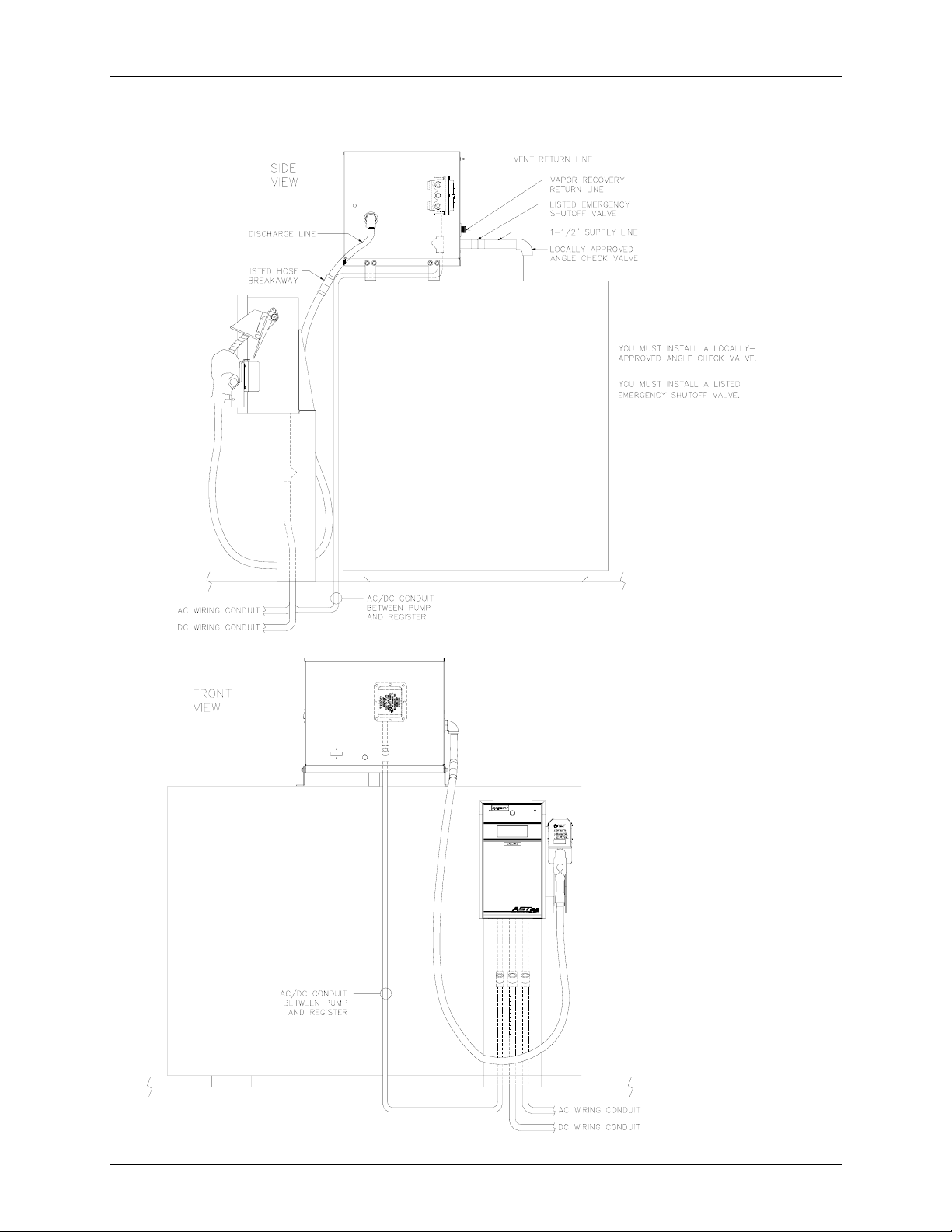
Vent Line
The vent line for standard units is vented to the atmosphere. Whenever possible, it is
recommended that the line be returned to the tank. A hole is provided above the normal vent
opening to allow this line to exit the pumping unit and return to the tank.
Vapor Recovery Option
This dispenser can be supplied with components necessary to provide vapor recovery. If the
dispenser is equipped for vapor recovery, a splitter is located in the pump housing. A 3/4"
discharge line will exit from the rear of the pump housing to return vapor/fluid to the tank. No
changes are required to the nozzle hook or boot assembly when using vapor recovery nozzles.
Please note that the vapor recovery nozzles approved for use are the "short spout" type. The
following nozzles and hose are approved for use with vapor recovery systems:
Nozzles: Emco Wheaton Model A4015
Husky Corp. Model 5010
OPW Model 211V
Hose: UL-Listed Hose Assembly
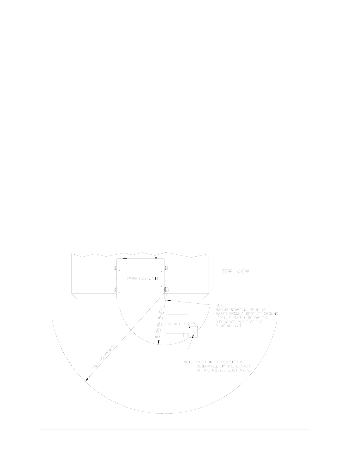
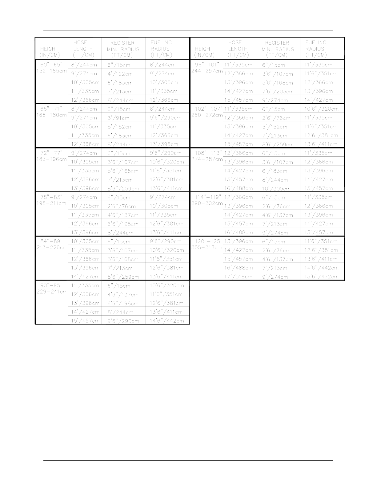
Hose Length Estimator
Use the chart on the next page to estimate the length of hose needed for your 9820Q application.
The correct length will prevent the hose from touching the ground when the nozzle is placed into
the nozzle boot/hook arrangement of the register. This chart assumes that the 9820Q register is
mounted on the standard pedestal and that the bottom of the pedestal is mounted flush with the
bottom of the tank. The illustration below provides a visual reference for the chart.
4 MDE-4339 9820Q ASTRA Installation/Operation • July 2004
Page 11
Installation
Key for Chart Headings
Height Measurement from the ground to the hose connection assuming the pumping unit is mounted
on top of the tank with the feet provided.
Tank height + 6" , standard units; tank height + 12" for vapor recovery units.
Hose Length Length of hose less nozzles and fittings.
Register Minimum Radius Indicates the closest t he register assembly can be to the specified st arting point; an y closer
than this distance may allow hose to touch the ground when unit is not in use. This radius is
measured starting from a point directly below pumping unit discharge to the center of the
nozzle boot/hook of the register assembly.
Fueling Radius Indicates the approximate fueling radius. Measured from a point directly below pumping unit
discharge to the nozzle.
MDE-4339 9820Q ASTRA Installation/Operation • July 2004 5
Page 12
GASBOY Series 9820Q
Typical Installation
See page 19 for cable requirements
6 MDE-4339 9820Q ASTRA Installation/Operation • July 2004
Page 13
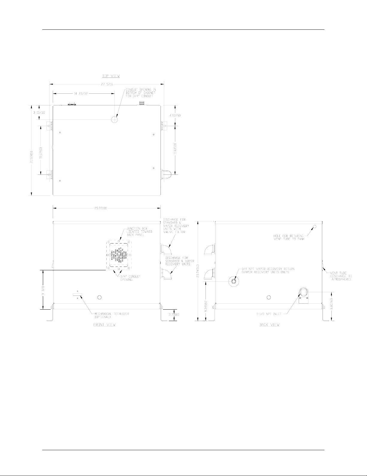
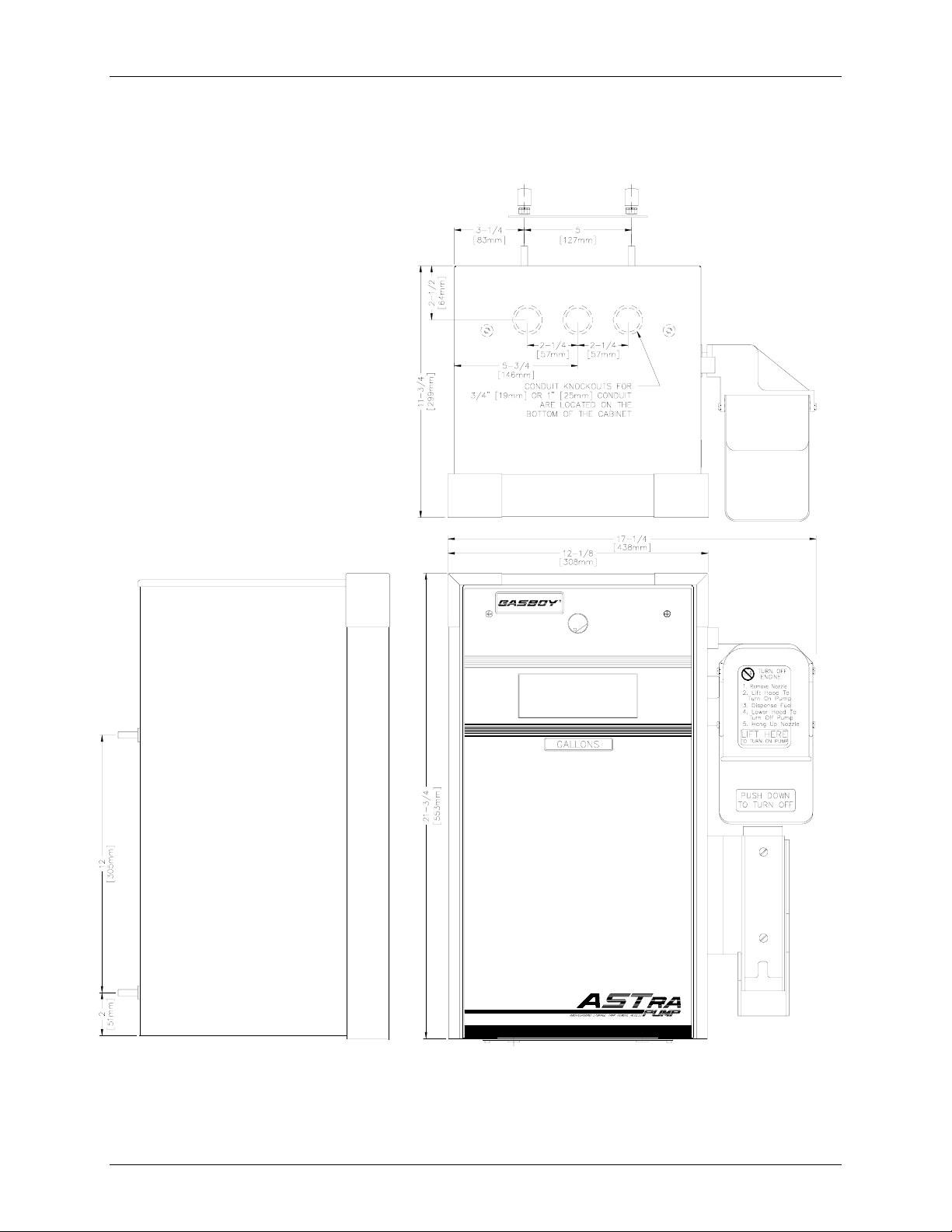
011931 Base Layout, Models: 9822Q, 9823Q
(View 1 - Pumping Unit Assembly)
Installation
MDE-4339 9820Q ASTRA Installation/Operation • July 2004 7
Page 14
GASBOY Series 9820Q
011930 Base Layout, Models: 9822Q, 9823Q
(View 2 - Register Assembly)
8 MDE-4339 9820Q ASTRA Installation/Operation • July 2004
Page 15
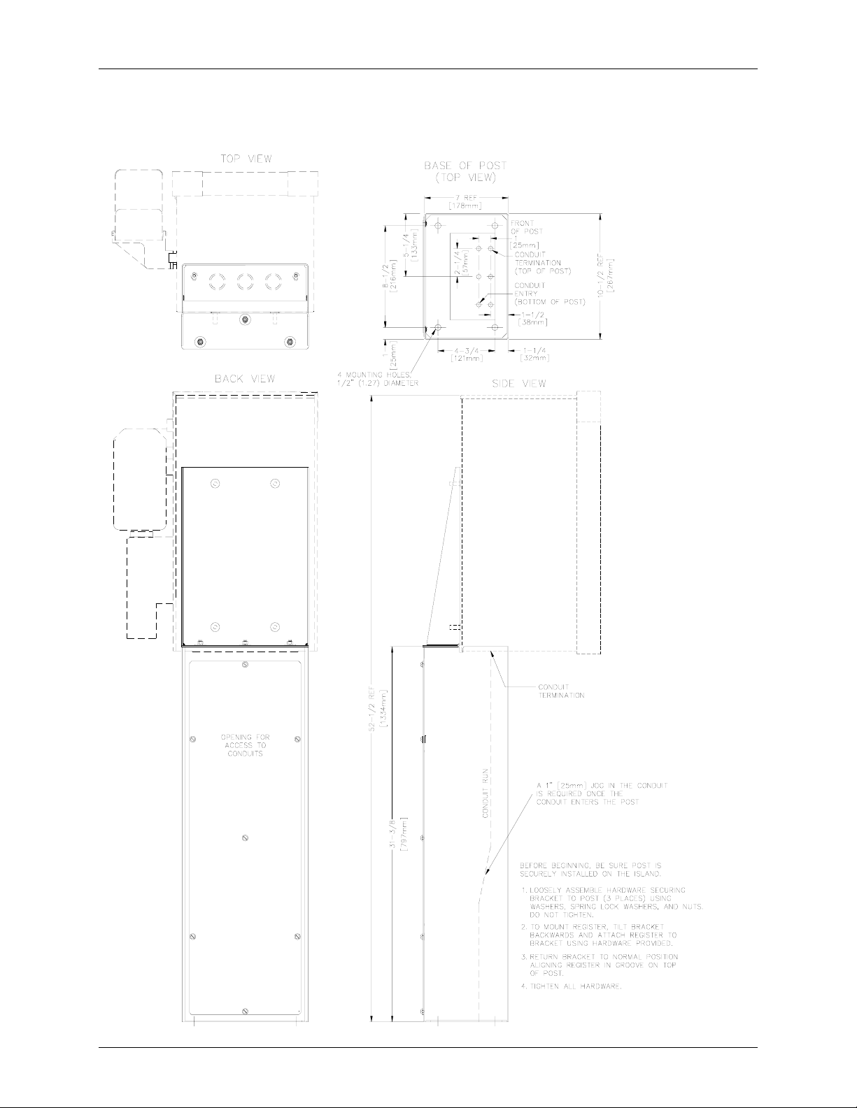
011884 Base Layout, Models: 9822Q, 9823Q
(Optional Post)
Installation
MDE-4339 9820Q ASTRA Installation/Operation • July 2004 9
Page 16

GASBOY Series 9820Q
011885 Base Layout, Models: 9822Q, 9823Q
(Side and Rear Brackets - View 1)
10 MDE-4339 9820Q ASTRA Installation/Operation • July 2004
Page 17

011885 Base Layout, Models 9822Q, 9823Q
(Side and Rear Brackets - View 2)
Installation
MDE-4339 9820Q ASTRA Installation/Operation • July 2004 11
Page 18

GASBOY Series 9820Q
12 MDE-4339 9820Q ASTRA Installation/Operation • July 2004
Page 19

3. Control Lines
Purpose
This section is provided to familiarize the installer with the control inputs and outputs that are
available for the Series 9820Q. It is recommended the installer read these descriptions to obtain a
better working kno wledge of the unit in order to guide him in planning the site wiring. Reference
Section 4 for a specific wiring diagram and installation notes.
The Series 9820Q may be provided for use with 230 VAC power for international applications.
The operating voltage for control lines to these units is shown in parentheses as (230 VAC Int'l).
If connecting the 9820Q to a GASBOY fuel management system, refer to the appropriate fuel
management system Installation Manual for detailed installation information.
Ground
To ensure proper operation of the equipment and provide the necessary safety factors, a good
ground line must be provided. A ground wire (preferably green) must be connected between the
ground screw of the register and the main electrical service panel. One (1) earth ground
connection is required per unit. The ground rod is to be a solid, corrosion-resistant conductor and
must be installed at the main electrical panel in accordance with the National Electrical Code. It
should be properly tied into the ground bus strip of the panel. We recommend the neutral and
ground bus strips be bonded together (unless prohibited by local codes).
Control Lines
Micro Feed
The Micro Feed is a 115 VAC (230 VAC Int'l) input required to power the microprocessor of the
register's electronics. This power must always remain on and must be on a separate breaker from
the control lines (Pump Motor Feed). In a site configuration using multiple units, the power for the
microprocessors of up to 8 units can be supplied by one breaker.
Micro Neutral
The Micro Neutral is a return line for AC current from the microprocessor of the dispensing unit to
the breaker panel.
Pump Motor Feed
The Pump Motor Feed is a 115VAC (230 VAC Int'l) input which is required to power the pump
and authorize the control line. This line is used to provide authorization for the unit (when enabled
through the DIP switche s). If this line is co nt rolled by a fuel management system using sol id state
relays, a resistor assembly must be installed between the Pump Motor Feed line and Feed Neutral
to prevent false triggering of the authorization input. The resistor assembly is 8.2K OHM, 10 Watt
(P/N C05818) for 115/230 VAC domestic and 30K OHM, 10 Watt (P/N C06683) for 230 VAC
international wiring.
The Pump Motor Feed line is used to power the slow flow and fast flow valves (when installed).
The power used to control the pump is also provided by this line. The Reset Complete signal used
for external monitoring of the pump originates from the Pump Motor Feed line.
MDE-4339 9820Q ASTRA Installation/Operation • July 2004 13
Page 20

GASBOY Series 9820Q
Neutral Feed
The Neutral Feed is the AC current return line back to the breaker panel for all attached devices
(pump motor, solenoid valves).
Slow Fl ow (Reset Comp lete/Switch Detect)
The Slow Flow line is a 115VAC (230VAC Int'l) output which is used to control the slow flow
valve of the optional solenoid valve. This line also indicates when the reset process is complete
and the unit is ready to dispense product. This line can be used in conjunction with a fuel
management system (for systems other than the Gasboy CFN Series systems).
This line is capable of supplying 300 mA AC maximum (170 mA maximum if already connected
to the optional valve). This line must not be shorted to any conduit or chassis metal, mis-wired, or
be connected to any equipment requiring more than stated maximum allowable current. If these
restrictions are not followed, damage to the CPU PCB will occur.
Fast Flow
The Fast Flow line is a 115VAC (230VAC Int'l) output which is used to control the fast flow valve
of the optional solenoid valve.
This line is capable of supplying 300 mA AC maximum (170 mA maximum if already connected
to the optional valve). This line must not be shorted to any conduit or chassis metal, mis-wired, or
be connected to any equipment requiring more than stated maximum allowable current. If these
restrictions are not followed, damage to the CPU PCB will occur.
Phase 2 Feed
The Phase 2 Feed is a hot feed which is the opposite phase of the pump motor feed. This line and
the pump motor feed are used for 230VAC motor applications. If connected to equipment
requiring control of the autho rization input, the Phase 2 Fee d should be switched through a
separate relay to prevent false triggering of the authorization signal.
Pulser
These lines are used to connect the pulser, mounted in the pumping unit, to the electronics in the
register assembly. These are DC voltage lines and provide the information necessary for the
register assembly to monitor the quantity of product dispensed. These lines are for internal use
only and must not be used for the pulse output (for external monitoring of the unit). Use the
optional Pulse Output interface if external pulses are required.
Pulse Output
This option provides a DC pulser output to indicate the quantity dispensed. This is an open
collector output. This output can sink up to 150 milliamps DC at voltages up to 24 VDC. The
pulse rate can be configured by a sealable DIP switch for rates of 1, 10, 100, 250, 500, or 1000
pulses per gallon or 1, 10, 100 or 250 pulses per liter. This output should only be used when
monitoring of the unit's operation is desired.
14 MDE-4339 9820Q ASTRA Installation/Operation • July 2004
Page 21

RS-485
Control Lines
When the dispensing unit includes the optional RS-485 interface, RS-485 lines are provided. This
interface allows the user to connect a GASBOY CFN Series System or TopKAT system directly to
the Series 9820Q dispensing unit.
MDE-4339 9820Q ASTRA Installation/Operation • July 2004 15
Page 22

GASBOY Series 9820Q
16 MDE-4339 9820Q ASTRA Installation/Operation • July 2004
Page 23

4. Wiring
Wiring
☎☎☎☎ Customers and installers having any questions pertaining to the installation should contact their
GASBOY distributor.
Wiring Precautions
The quality of the electrical installation is a major factor in maintaining proper safety levels and
providing trouble-free operation of your GASBOY pump. To assure a quality installation, follow
these rules:
1. All wiring must be installed to conform with all building/fire codes, all Federal, State, and
Local codes, National Electrical Code, (NFPA 70), NFPA 30, and Automotive and Marine
Service Station Code (NFPA 30A) codes and regulations. Canadian users must also comply
with the Canadian Electrical Code.
2. Use o nly threaded, rigid, metal conduit.
3. Use only UL-Labeled insulated gasoline- and oil-resistant stranded copper wiring of the
proper size.
4. Wire connections should be tightly spliced and secured with a wire nut; close off the open end
of the wire nut with electrical tape.
5. The line to the motor should be on a separate circuit and installed on a 20 to 30 AMP breaker
depending on the motor size and/or the voltage setting.
6. Install an emergency power cutoff. In addition to circuit breaker requirements of NFPA 70
and NFPA 30A, a single control which simultaneously removes AC power from all site
dispensing equipment is recommended. This control must be readily accessible, clearly
labeled, and in accordance with all local codes.
In a fuel management system application, the EMERGENCY STOP and STOP keys on the
console and/or the optional EMERGENCY STOP button on the Island Card Reader do not
remove AC power from equipment and under certain conditions, will not stop product flow.
In order to provide the highest level of safety to you, your employees, and customers, we
recommend that all employees be trained as to the location and procedure for turning off
power to the entire system.
To reduce the risk of electrical shock when servicing, turn off and lock out all power to the pump.
AVERTISSEMENT
Pour réduire le risque de choc électrique lors de l'entretien/révision, coupez totalement le courant à la
pompe/distributeur.
Have the pump installed by a competent installer/electrician.
WARNING:
MDE-4339 9820Q ASTRA Installation/Operation • July 2004 17
Page 24

GASBOY Series 9820Q
Ground
To ensure proper operation of the equipment and provide the necessary safety factors, this unit
must be grounded. A ground wire (preferably green) must be connected between the ground screw
of the register and the main electrical service panel. One (1) earth ground connection is required
per unit. The ground rod is to be a solid, corrosion-resistant conductor and must be installed at the
main electrical panel in accordance with the National Electrical Code. It should be properly tied
into the ground bus strip of the panel. We recommend the neutral and ground bus strips be bonded
together (unless prohibited by local codes).
Circuit Breakers
Power to the unit must be supplied from dedicated breakers. No other equipment should be
powered from these breakers. AC power for the micro power must come from a different breaker
than that of the pump. This not only provides electrical isolation for the micro power, but allows
the unit to be disabled without shutting off power to the microprocessor PCB. The AC power for
the micro power may be grouped together for multiple units. It is recommended that no more than
8 units be supplied from one breaker.
Pump Motor
Pumps are shipped from the factory with motors wired according to the specifications given on the
order as t o kind of current, frequency and voltage.
Very often on installation, it becomes necessary to change the original setting to suit the AC power
source. To do this, locate the motor change-over plate and remove the screw which secures it in
place. Slide the plate so that the desired voltage, as marked on the plate, lines up with the screw
hole. Reinsert the screw and secure the plate in place.
Many motor failures result from improper setting of the motor change-over plate. If set for 115
VAC and a 230 VAC feed is used, the motor will burn out after running only a short time. If set
for 230 VAC and a 115 VAC feed is used, the motor will run very slowly and the starting field will
soon burn out.
Pulse Output
The Pulse Output option provides the means for an external system to monitor the quantity that is
dispensed by the 9820Q dispensing unit. A description of the interface is provided in Control
Lines, Pulse Output, in Section 3. Consult the wiring diagrams provided in Wiring in Section 4,
along with the installation manual of the system that will be connected to the 9820Q dispensing
unit.
RS-485
The RS-485 option provides the means for direct connection to a GASBOY CFN Series System or
TopKAT System. Consult the wiring diagrams provided in Wiring in Section 4, along with the
installation manual of the CFN Series System or TopKAT System for proper wiring.
18 MDE-4339 9820Q ASTRA Installation/Operation • July 2004
Page 25

Wire Size
Wiring
The AC wire size for the Micro Feed and Neutral should be 14 AWG. This gauge of wire will be
sufficient for runs up to 300 feet from the breaker panel to the dispensing unit. Sites with distances
over 300 feet should use 12 AWG wire. In cases where multiple units are powered from the same
breaker through the same wires, the gauge of the wires should be incr eased to handle the added
load according to the distance from the breaker panel.
The AC wire size of the Pump Motor Feed, Pump Motor, Feed Neutral, and Neutral is
dependent upon the HP rating of the pump motor, the voltage at which the pump will be operated
(115/230 VAC), and the distance from the circuit breaker panel to the pump. The chart below
should be used as a guide in selecting the proper wire size according to the specific installation
requirements.
The AC wire size for the Slow Flow, Fast Flow lines should be 14 AWG (when they are used).
The DC wire size for the Pulser lines connecting the pumping unit to the register assembly must
use four conductor, 18 AWG shielded cable (Belden 89418, Gasboy P/N C08864). This cable
allows the pulser wires to run in the same conduit as the AC wiring for the short distance between
the pumping unit and the register assembly. Belden 89418 is rated as follows:
Gas and Oil resistant insulation & jacket
18 AWG tinned, stranded, copper
Four conductors
300 volt maximum operating voltage
Aluminum/Mylar shielded with drain wire
Twisted-pair shielded cable is highly recommended for the Pulse Output or RS-485 field wiring
(when they are used). This type of cable provides superior noise immunity and must be used for
distances over 100 feet or any time pulse output or RS-485 wiring is included in the same conduit
as the AC wires. This cable must meet the following specifications:
Conductor: 18 AWG stranded wire. 2 twisted-pairs.
Shield: Foil-wrapped 100% coverage and/or tinned copper braid 90% coverage
Drain Wire: Stranded, tinned copper, 20 AWG or larger/or braided shield
Voltage Rating: Maximum operating voltage of 600V
Environmental: Gas- and oil-resistant; suitable for wet or dry locations.
GASBOY can supply Belden 1063A (P/N C09655) which is a UL-Listed, 4-conductor cable that
meets the requirements listed above. NOTE: Belden 1063A is UL-Listed but not CSA listed.
Cable with a voltage rating of less than 600V must be installed in a conduit separate from all AC
wires.
See the GASBOY Fuel Management System Installation Manual for specific requirements.
MDE-4339 9820Q ASTRA Installation/Operation • July 2004 19
Page 26

GASBOY Series 9820Q
Conduit
All wiring to the GASBOY Series 9820Q dispensing unit must be installed in threaded, rigid,
metal conduit. PVC IS NOT ACCEPTABLE. Wiring between the 9820Q register and pumping
unit is installed in a single conduit. This includes the wiring for the AC control of the pumping
unit and the internal pulser. A special cable, as described in Section 4, Wire Size, must be used for
the connection between the pulser inside the pumping unit to the register assembly.
It is recommended that high voltage AC power wires to the register assembly (not between the
register and pumping unit), be installed in separate conduit from the low voltage pulser output
wires (when used). However, if AC and DC power wires share c onduit, DC wiring must consist o f
UL-Listed cable with the specifications described in Section 4, Wire Size. Only AC wires for the
system and dispensers can be installed in this conduit for this application. Wiring between a Fuel
Point Reader (FPR) and its pre-amp junction box is intrinsically safe and must be run in a conduit
with only other intrinsically safe wiring. It cannot be run in conduit with AC, DC, RS-485, or
pulser wiring, regardless of the cable type used. See the Fuel Point Reader Installation and
Retrofit Manual, C35628 for details.
The GASBOY Warranty will not apply to any dispenser in which the AC and DC wires are run in
the same conduit, J-Box or wireway except as noted. The GASBOY Warranty will not apply to
any dispenser using PVC as conduit.
When the GASBOY Series 9820Q dispensing unit is being installed with a fuel management
system other than a GASBOY system, see the manufacturer's installation manual for their specific
conduit requirements.
All wiring and conduit runs must conform with all building/fire codes, all Federal, State, and Local
codes, National Electrical Code, (NFPA 70), NFPA 30, and Automotive and Marine Service
Station Code (NFPA 30A) codes and regulations. Canadian users must also comply with the
Canadian Electrical Code.
Use the following charts as a guideline for determining the necessary conduit sizes for wiring of
the GASBOY Series 9820Q dispensing unit. When actually determining the size of conduit, it
may be necessary to increase the size of conduit because of a long run or large amount of bends.
The installer should determine the orientation of the wire runs according to the layout of the
components at the site and the applicable GASBOY wiring diagrams.
To determine conduit size needed, use the THHN/THWN Wire Areas table (left) to find the area
for each wire gauge. Add up all wire areas. Use the Areas of Trade Size Conduit Table (right) to
select the smallest number in the 25% fill area (based on NEC 501-1) that comes closest without
exceeding the total wire area.
20 MDE-4339 9820Q ASTRA Installation/Operation • July 2004
Page 27

Terminal Block ID
The terminal blocks shown below are located in the register assembly.
Wiring
MDE-4339 9820Q ASTRA Installation/Operation • July 2004 21
Page 28

GASBOY Series 9820Q
023866 Wiring Diagram, Models: 9822Q, 9823Q
Domestic 115/230 VAC
NOTES:
1. All wiring and conduit runs must conform with all building/fire codes, all Federal, State, and
Local codes, National Electrical Code, (NFPA 70), NFPA 30, and Automotive and Marine
Service Station Code (NFPA 30A) codes and regulations. Canadian users must also comply
with the Canadian Electrical Code.
2. Pump motor can be wired as 230 VAC to reduce current draw. See breakaway view of 230
VAC PUMP MOTOR. All other wiring should remain the same except for the addition of
the L2 (requires 230 VAC breaker for control). If connected to equipment requiring control
of the authorizat ion input, the Phase 2 Feed should be switched through a separate relay to
prevent false triggering of the authorization signal.
3. If the PUMP MOTOR line is controll ed by a fuel management system using solid stat e
relays, a resistor assembly must be installed between the Pump Motor Feed line and Neutral to
prevent false triggering of the authorization input. The resistor assembly is 8.2K OHM, 10
Watt (P/N C05818) for 115/230 VAC domestic and 30K OHM, 10 Watt (P/N C06683) for
230 VAC international wiring.
4. SLOW FLOW and FAST FLOW lines are typically used when connecting to an optional
valve. Each of these lines is capable of supplying 300 mA AC maximum (170 mA AC
maximum if already connected to the optional valve). These lines must not be shorted to
any conduit or chassis metal, mis-wired, or connected to any equipment requiring more
than stated maximum allowable current. If these restrictions are not followed, damage
to the CPU PCB will occur.
5. Use the wire size chart listed when determining the wire size for the control wiring.
22 MDE-4339 9820Q ASTRA Installation/Operation • July 2004
Page 29

023866 Wiring Diagram, Models: 9822Q, 9823Q
Domestic 115/230 VAC
Wiring
WARNING:
Failure to follow the correct wiring diagram and all the listed notes and precautio ns may result in
damage to the CPU PCB.
MDE-4339 9820Q ASTRA Installation/Operation • July 2004 23
Page 30

GASBOY Series 9820Q
023867 Wiring Diagram, Models: 9822Q-2, 9823Q-2 International 230VAC
NOTES:
1. All wiring and conduit runs must conform with all building/fire codes, all Federal, State, and
Local codes, National Electrical Code, (NFPA 70), NFPA 30, and Automotive and Marine
Service Station Code (NFPA 30A) codes and regulations. Canadian users must also comply
with the Canadian Electrical Code.
2. If the PUMP MOTOR line is controll ed by a fuel management system using solid stat e
relays, a resistor assembly must be installed between the Pump Motor Feed line and Neutral to
prevent false triggering of the authorization input. The resistor assembly is 30K OHM, 10
Watt (P/N C06683) for 230 VAC international wiring.
3. SLOW FLOW and FAST FLOW lines are typically used when connecting to an optional
valve. Each of these lines is capable of supplying 300 mA AC maximum (170 mA AC
maximum if already connected to the optional valve). These lines must not be shorted to
any conduit or chassis metal, mis-wired, or connected to any equipment requiring more
than stated maximum allowable current. If these restrictions are not followed, damage
to the CPU PCB will occur.
4. Use the wire size chart listed when determining the wire size for the control wiring.
24 MDE-4339 9820Q ASTRA Installation/Operation • July 2004
Page 31

023867 Wiring Diagram, Models: 9822Q-2, 9823Q-2 International 230VAC
Wiring
WARNING:
Failure to follow the correct wiring diagram and all the listed notes and precautio ns may result in
damage to the CPU PCB.
MDE-4339 9820Q ASTRA Installation/Operation • July 2004 25
Page 32

GASBOY Series 9820Q
26 MDE-4339 9820Q ASTRA Installation/Operation • July 2004
Page 33

5. Pump Operation
Overview
This section describes the operation of the pump. It shows how to access the electronic
components, how to set the internal switches, the optional battery back-up power supply, how to
view and reset the electronic totalizers using the actuator, how to operate the pump, and how to
lock the nozzle.
Pump Operation
MDE-4339 9820Q ASTRA Installation/Operation • July 2004 27
Page 34
GASBOY Series 9820Q
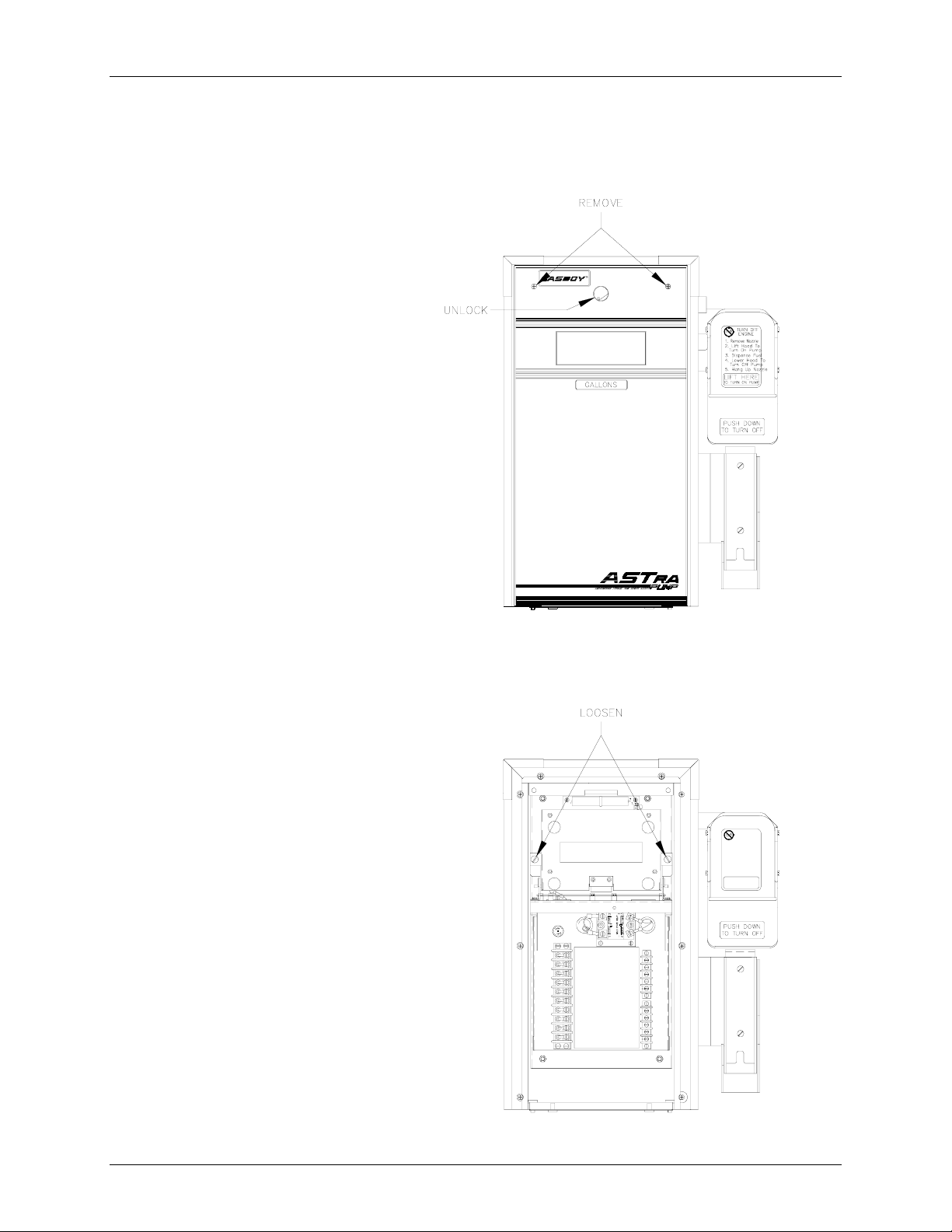
Electronic Component Access
Before attempting to start-up the 9820Q, it is important to become familiar with the location of
some key components as well as the various switch-selectable operating modes.
1. Unlock and remove the
front panel. Remove the
two screws located at the
top of the door assembly.
Pull out on the top of the
door and lift the door
assembly to remove it.
2. Loosen the two screws located
on the left and right door
support brackets and pivot
display panel down.
28 MDE-4339 9820Q ASTRA Installation/Operation • July 2004
Page 35

CPU Switch Settings
The 9820Q can be configured for various
operating conditions using the switches
located on the CPU PCB. Check these
switches and change their settings if
necessary. Switch settings should be
changed with the power switch OFF.
The new settings are read by the CPU
PCB when the power is turned ON again.
SW1
SW1-1 Baud Rate
This switch is set to reflect the communication rate of
the GASBOY RS-485 pump loop; open for 9600 baud
or closed for 1200 baud. The GASBOY CFN system
and TopKAT communicate at 9600 baud.
Baud Rate
9600
SW1-1
Open
Pump Operation
Fuel System
CFN
TopKAT top-mount
TopKAT electronic
None currentlyClosed1200
supported
SW1-2 Mode
If the 9820 is controlled by a GASBOY CFN
or TopKAT electronic fuel management
Mode
On-line
SW1-2
Open
system, the switch should be open (on-line
mode). If the 9820 is controlled by a
GASBOY Series 1000 or TopKAT
mechanical system, or controlled by any non-
Closed Series 1000Standalone
GASBOY system, or not controlled by any
fuel management system at all, the switch
should be closed (standalone mode). NOTE:
The 9820 is shipped in standalone mode.
SW1-3, SW1-4 Delay Time
These two switches set the delay time used by leak detectors in
submersible pump applications. The delay time is the period between
activation of the submersible pump and activation of the slow flow
valve. This time should be set according to the type of leak detector
installed on the submersible pump to allow a normal leak test for each
transaction. The delay time should be set to zero seconds for suction
pumps.
SW1-5
Not used.
Fuel System
CFN
TopKAT top-mount
TopKAT electronic
TopKAT Mechanical
All non-GASBOY systems
No fuel system
Delay Time
0 seconds
4 seconds
5 seconds
6 seconds
SW1-3
Closed
Closed
Open
Open Open
SW1-4
Closed
Open
Closed
MDE-4339 9820Q ASTRA Installation/Operation • July 2004 29
Page 36

GASBOY Series 9820Q
SW1-6 Authorization
This switch allows activation of the 9820Q from some
types of fuel management systems. When the switch
is closed, a 115 VAC (230 VAC Int’l) signal must be
present on the Control Feed line for pump activation
to occur (required setting for Series 1000, TopKAT
mechanical, and all non-GASBOY systems ). When
open, the 9800 ignores the Control Feed line
Authorization
Yes
SW1-6
Closed
OpenNo CFN
Fuel System
Series 1000
TopKAT mechanical
All Non-GASBOY systems
TopKAT top-mount
TopKAT electronic
No fuel system
(required setting for CFN, TopKAT electronic, or no
fuel system).
SW1-7 Totalizers
This switch should be set to open for normal operation. When closed, this
switch enables the reset of the electronic totalizers. See View/Reset
Totalizers later in this section for details.
Reset
Normal
SW1-7Totalizers
Closed
Open
SW1-8
Not used.
SW2
This four-position switch pack serves a dual purpose: as an address setting when communicating on the GASBOY
RS-485 loop or TopKAT, or as a pulser output rate selector when pulser data is sent to a fuel management system
other than a GASBOY CFN or TopKAT.
Address Switches
A unique address identifier must be set when the 9820Q
is connected to the GASBOY RS-485 pump loop via the
9820Q RS-485 I/F PCB. Because there are 16 possible
address combinations, up to 16 units (single or twin) may
be connected to the pump loop. Addressing should start
at 1 and continue sequentially through 16. The physical
wiring order does not have to correspond with the address
order; that is the first unit on the RS-485 loop doesn't
have to be address 1. The chart at right gives the switch
settings and address selections.
Address
SW2-1
1Closed
2
Open Closed
3Closed
4
Open
5Closed
6
Open
7Closed
8
Open
9
Closed ClosedClosed Open
10
Open ClosedClosed Open
11
Closed ClosedOpen Open
12
Open ClosedOpen Open
13
Closed
14
Open
15
Closed
Open
SW2-2
Closed
Open
Open
Closed
Closed
Open
Open
Closed
Closed Open Open
Open
Open Open Open16
SW2-3
ClosedClosed
Closed
Closed
Open
Open
Open
Open
Open
Open
SW2-4
Closed
Closed
Closed
Closed
Closed
Closed
Closed
Closed
Open
Open
30 MDE-4339 9820Q ASTRA Installation/Operation • July 2004
Page 37

Pulser Output Rate Switches
When the 9820Q is connected to external control equipment
other than a GASBOY CFN system (standalone), the pulser
signals are sent out via the 9820Q Pump I/F PCB. The pulse
rate required by the monitoring equipment can be configured by
setting the switches as shown in the chart at right. The pulse rate
represents pulses per gallon (PPG, domestic) or pulses per liter
(PPL, international). For domestic units, the pulse rate can be up
to 1000 PPG. For international units, the pulse rate can be up to
250 PPL for all other models. This switch may need to be sealed
by a Weights and Measures paper seal if the 9820Q is used for
the resale of product.
Leading zero s are always suppressed in the hundreds and tens
positions to the left of the decimal point. When in standalone
mode, positions to the right of the decimal point are displayed
based on the pulse rate selected as shown in the table at right.
Timeout Switch
When the 9820Q is in standalone mode, it will turn off an active
hose if it doesn't detect pulses for 4 minutes, 15 seconds. This
timeout feature can be disabled by setting switch SW2-4 to
OPEN.
Pump Operation
Pulse Rate SW2-1 SW2-2 SW2-3
1Closed
10
100
250
500
1000
None
None
Pulse Rate Display
1:1 XXX.
10:1
100:1
250:1
500:1
1000:1
Timeout
Enabled
Disabled
Open Closed
Closed
Open
Closed
Open
Closed
Open
XXX.X
XXX.XX
XXX.XXX
XXX.XXX
XXX.XXX
SW2-4
Closed
Open
Closed
Open
Open
Closed
Closed
Open
Open
ClosedClosed
Closed
Closed
Open
Open
Open
Open
MDE-4339 9820Q ASTRA Installation/Operation • July 2004 31
Page 38

GASBOY Series 9820Q
ATC Information Sheet
By activating the magnet located at the opposite side of the totalizer, various items will appear on the
display:
1. Volume Display Displays uncompensated volume
2. Probe Temperature Display Display s probe temperature in Celsius only 0 23.2
3. Flow Reat Display Displays flow rate (in LPM only) 189.2
4. Software Version Display Displays software version number 1.30
5. ATC Status Display Displays ATC Status 842.2
On the status display, the rightmost digit (2) indicates whether or not temperature compression is enabled,
and if so, what product is being dispensed. 0=temperature compensation enabled; 1=product is gasoline
and compensation is enabled; 2=product is diesel and compensation is enabled.
On the status display, the leftmost digits (842) are error indicators which are blank when the
corresponding error condition is not active. When any of these digits are displayed, their meanings are:
8=temperature probe fault is detected; 4=pulser error occurred; 2=exceptional reset was detected.
Setting the DIP Switches
# Use Setting
1 Product 1 ON=Diesel; OFF=Gasoline
2 Product 2 ON=Diesel; OFF=Gasoline
3 Not Used
4 Not Used
5 Pulser Multiplier ON=9850; OFF=9852/9853
6 # of Probes ON=2, OFF=1
7 Pulser Adder ON=9840
8 ATC ON=ATC on; OFF=ATC off
0023.43
32 MDE-4339 9820Q ASTRA Installation/Operation • July 2004
Page 39

Battery Back-Up Power Supply
9820Q models can be equipped with an optional battery back-up power supply. This allows the
last transaction data to be displayed for a minimum of 15 minutes. After the batteries reach a
certain low-voltage point, the power will automatically shut off. If you need to shut off the battery
power before the low-voltage point is reached, momentarily disconnect, then re-connect, the cable
that plugs into P1 on the power supply.
Pump Operation
View/Reset Totalizer
Electronic Totalizer
The 9820Q stores a running quantity total. This electronic totalizer works independent of the
optional mechanical totalizer that may be installed, and is shown as whole gallons (liters) on the
displays (decimal point is shown, although it is disregarded ). The total izer data is stored in
battery-backed memory. The 9820Q is supplied with an actuator (shown in the above illustration)
which allows you to view and reset the electronic totalizer. When the 9820Q is shipped, the
actuator is attached with a tie wrap to the electronic chassis behind the register door. At
installation or startup, cut the tie wrap and remove actuator. Retain for future use.
MDE-4339 9820Q ASTRA Installation/Operation • July 2004 33
Page 40

GASBOY Series 9820Q
To view the pump totalizer, make sure the pump handle is off and no transaction is in progress.
Locate the unit of measure indication (i.e., GALLONS) below the display window. Touch this
area with the actuator as shown. The totalizer data will be displayed for 10 seconds. If more time
is needed, touch the actuator to the same area for an additional 10 second period.
To reset the electronic totalizer, follow the disassembly procedure outlined under Electronic
Component Access earlier in this section. Turn off the breaker supplying the 9820Q AC power.
Close SW1-7 on the CPU PCB. Hold the actuator against the totalizer bracket and have someone
turn the breaker on. The display should change to all zeroes. Remove the actuator and open SW1-
7. Ater opening switch 1-7, power to the register must be recycled to recognize the switch change.
NOTE: Returning switch 1-7 to the open position prevents the totalizer from being reset the next
time the actuator is used to read it.
Mechanical Totalizer
Some 9820Q models contain an optional mechanical totalizer. The totalizer has 8 digits; 7 whole
gallons and 1 tenth-gallon column, 8 whole digits for liters. The mechanical totalizer is located on
the front right side of the pumping unit.
Operating Sequence
The exact sequence of events that occurs during the operation of the pump is determined by
various switch settings, inputs, and the user. A typical transaction is explained below.
1. Turn on the pump handle. If AC is present on the Pump Motor Feed line, the reset cycle
begins. The display:
• goes blank for one second
• shows all 8's for one second
• goes to 0.000 (gallons) or 0.00 (liters) and remains for one second.
The pump motor turns on. If equipped, the slow flow valve turns on.
2. The user begins to dispense fuel. Quantity will not be recorded on the display until 0.010
gallons (0.04 liters) are reached, however, all pulses will be sent out on the Pulse Output line,
if equipped. At 0.010 gallons (0.04 liters), the fast flow valve turns on, if equipped.
3. The pump continues to run until one of the following conditions occurs. These conditions
turn off all relays.
• The handle is turned off.
• The Pump Motor Feed line is turned off.
• A pulser error is detected.
• A timeout of 255 seconds is reached. If connected to a fuel management system, the
timeout loaded into the system will be used.
• A quantity of 990.000 gallons (9900.00 liters) is reached. If connected to a fuel
management system, the limit set in the system will be used.
• The pump is halted by an operator of a fuel management system.
• An AC power failure occurs.
4. The 9820Q continues to monitor for pulses until a 2 second period with no pulses occurs. At
this time the transaction is considered completed.
34 MDE-4339 9820Q ASTRA Installation/Operation • July 2004
Page 41

Nozzle Locking
A locking mechanism is supplied as part of the hook arrangement on each 9820Q. This will allow
the unit to be locked thus preventing use of the dispenser. A lock with a shackle clearance of at
least 2-1/2" is required to lock the pump (i.e., Master No. 1LJ-D). To lock the nozzle in place,
follow the instructions below:
1. Insert the nozzle onto the hook assembly with the nozzle tip inside of the boot.
2. Slid e the rear br acket of the nozzle hook assembly upward until the holes near the bottom of
the nozzle are aligned.
3. Sl ide the open p adlock through holes in the moveable a nd stationary portions of the hook
arrangement, thus capturing the nozzle in place. (Note that the four holes will not align until
the moveable bracket has been slid upward.)
4. Close the lock.
While the nozzle is locked in place, the nozzle cannot be removed from the nozzle hook and the
dispenser cannot be turned on.
Pump Operation
MDE-4339 9820Q ASTRA Installation/Operation • July 2004 35
Page 42

6. Start-Up and Test
Installation Completion Checklist
Review the information below to verify the proper installation of the Series 9820Q dispensing unit.
If the installation does not meet criteria listed, correct the problem before the start-up is
performed.
1. To avoid damage to the CPU PC board, verify that the SLOW FLOW and FAST FLOW
wires are not shorted to any co nduit or chassis metal, mis-wired, or connected to any
equipment requiring more than stated maximum allowable current.
2. The register and pumping unit must be properly secured.
3. All plumbing must be complete and tight. All liquid-carrying lines must be checked for
leaks.
4. When DC pulse output lines are used in the pump for connecting to GASBOY fuel
management systems, the AC and DC wires must not share any co nduits, junctio n boxes, or
troughs except a s noted in Sectio n 4, Wire Size.
5. All conduit work must be complete. All junction box covers must be secured. Conduits
should not be sealed until the wiring is verified through pr oper operation.
6. The unit must be properly grounded.
7. Before any testing begins, remove any water in the tank through a fill opening, using a suitable
pump. Do not use the GASBOY pump to remove water. Serious damage may occur.
8. A sufficient volume of fuel must be put in the tank to insure that the liquid level is above the
bottom of the suction pipe.
Start-up and Test
MDE-4339 9820Q ASTRA Installation/Operation • July 2004 36
Page 43

Start-Up
After successfully verifying the installation against the completion checklist, the unit is ready for
start-up. Follow the procedure below to perform an orderly start-up of the Series 9820Q.
1. Verify that all switches on the CPU PCB are set properly for the various operating conditions
as explained in Section 5.
2. Turn on the circuit breakers for the microprocessor.
3. Authorize the unit thr ough the fuel management system, if availa ble.
4. Remove the nozzle from its holder and turn on the pump handle. Verify that the display goes
through the proper reset sequence as explained in Section 5, Operating Sequence.
Note: when power is turned on for the register, you must reset the handle twice to go through
the reset sequence.
5. Dispense fuel. Verify that the high flow valve opens, if equipped. Check all plumbing for
leaks at this time.
6. Turn the pump handle off. Open the nozzle. No fuel should be dispensed at this time.
7. Verify that the correct quantity was recorded by the fuel management system, if available.
8. Run t he unit through all sta ndard calibration procedures.
9. Reset the electronic totalizer as described in View/Reset Totalizer in Section 5.
Post Start-Up Tests
Start-Up and Test
Voltage
Tightness
Belts
Calibration
The incoming voltage to the pump should be checked and any reading not within 10% of rated
voltage should be corrected before testing is continued. It is good practice to take voltage readings
while the pump is operating on bypass and also while making a delivery. Any voltage drop in
excess of 10% during either of these operating states should be considered a low voltage condition.
Corrective action should be taken to insure an adequate power supply to the pump.
After determining that the pump is operating satisfactorily and the system is fully primed, check
the pump and piping to make sure that all connections are tight.
Since belts do stretch slightly during the first few minutes of operation, check the belt tension after
completing the operational test; a properly tightened belt will permit twisting the belt 180 degrees
midway between the motor and pump pulleys.
On the 9822Q and 9823Q, the belt can be tightened by loosening the cap screw which holds the
idler arm and sliding the arm to obtain the correct belt tension of 6-3/4 lbs. (+ 3/4). When the
adjustment is complete, remember to retighten the cap screw.
All GASBOY pumps are adjusted for accurate measure at the factory. However, since the
conditions of the installation can affect pump accuracy, it is the responsibility of the installer to
check the pump for accuracy and make any needed adjustments. Where required, it is the owner's
responsibility to report this device to the local Weights and Measures officials for their inspection
before the unit is put into service.
Each meter is equipped with a mechanism for calibration, located on the side of the meter. To
adjust the volume dispensed:
MDE-4339 9820Q ASTRA Installation/Operation • July 2004 37
Page 44

GASBOY Series 9820Q
1. Check meter registration by delivering product to a reliable, accurate, 50 or 100 gallon prover.
2. Remove the seal wire from the locking pin.
3. Remove locking pin and turn wheel to adjust measurement. Turn clockwise to decrease the
amount in the prover to match the display, turn counter-clockwise to increase the amount in
the prover to match the displayed. Moving the wheel one hole position changes the
calibration by 2/3 cubic inch per 5 gallons. To change by half of this amount, you may utilize
the alternate locking pin hole on the opposing side of the calibration wheel.
4. Rep eat process until volume in prover and amount recorded are within tolerance.
5. After calibration is complete, reinstall locking pin and secure in place using a seal wire.
38 MDE-4339 9820Q ASTRA Installation/Operation • July 2004
Page 45

7. Preventive Maintenance
General
GASBOY pumps are designed and constr ucted to give many years of uninterrupted servic e. In
fact, operators report years of trouble-free operation with absolutely no service expense. Yet,
certain parts of a pump are bound to wear, and GASBOY therefore recommends a periodic
inspection, at least twice a year, for such things as fuel leaks, belt tension and condition,
lubrication and strainer cleanliness. If such a procedure is followed, any small adjustments that are
necessary can be made before expensive, annoying breakdowns occur. The result of this sound
approach is continuous, profitable service from all of your GASBOY equipment.
WARNING:
To reduce the risk of electrical shock when servicing, turn off all power to the pump.
Hints For Better Pump Performance
Demand Competent Service
If your pump should stop or fail to operate properly, don't depend upon the repair service of a
general mechanic unless he is thoroughly familiar with the mechanism. Experience shows that the
repair results will be much more satisfactory if you demand the service of a competent
representative of the pump manufacturer. GASBOY has a Distributor Network which services fuel
dispensing and management systems in every section of the country.
Preventive Maintenance
Use Authorized Parts
Should excessive wear, rust, or corrosion of parts cause inefficient operation, it is always best to
replace them immediately; but if you want the best results and continuity of the Underwriters'
Label on your pump, be sure they are new authorized service parts supplied by GASBOY. Every
part of a pump is carefully designed for a particular purpose. If it is replaced by an incorrect or
substandard substitute, pump operation will be unsatisfactory. Always use new gaskets or seals
when servicing or rebuilding GASBOY equipment; do not re-use the old ones.
Operate With Reasonable Care
Like any machine, the pump that is operated with reasonable care will last longer and give better
service. Abuse should be avoided (such as dropping the nozzle on the ground, operating the unit
with a dirty strainer, dragging the hose across the concr ete island or driveway, running the pump
with the nozzle closed for more than two minutes, etc.). The time and care given to your pumps
will be returned to you in the form of dependable service.
Preventive Maintenance Checklist
Keep Water Out
Water tends to collect in storage tanks. This is due to moisture-laden air being drawn into the
storage tank and condensing, or to defective fill openings that are not properly protected with
watertight covers. Storage tanks should be checked after every fill-up for water and removed with
a sump pump, to forestall serious damage to equipment. Water, sediment, and other foreign matter
that accumulates in the tank can be drawn up into the pump and cause failures.
MDE-4339 9820Q ASTRA Installation/Operation • July 2004 39
Page 46

GASBOY Series 9820Q
Clean the Dial Face
Clean the dial face with a soft, clean, damp cloth as often as necessary.
Clean the Strainer
Clean the strainer immediately after the pump has been installed and tested, and again after a few
hundred gallo ns have been delivered. Thereafter, once every six months, or as r equired.
The symptoms of a dirty or clogged strainer in a pump are slow delivery, noisy operation, and
pulsation. To clean the strainer, turn off AC power to the pump. Locate the Suction Strainer Cap
on the plumbing unit and unscrew it to access and remove the strainer. Use compressed air
blow the dirt out of the strainer.
*Wear protective safety goggles or glasses when using compressed air.
Change the Filter
If the unit is equipped with a filter, check and change it at regular intervals. A dirty filter in a
pump will cause a slower delivery rate. Refer to the accessories section of your parts manual to
ensure that you replace the filter with one designed for your model. Always use a drip pan directly
below the filter when removing the cartridges to prevent contamination of both the soil and the
electrical components within the cabinet.
* to
Adjust the Belts
With the proper care, belts will give exceptionally good service. A loose belt not only cuts down
dispensing speed, due to slipping, but also results in excessive wear. A properly tightened belt will
allow twisting the belt 180 degrees midway between the motor and the pump pulleys.
On the 9822Q and 9823Q models, the belt can be tightened by loosening the cap screw which
holds the idler arm and sliding the arm to obtain the correct belt tension of 6 3/4 lbs (+ 3/4). When
the adjustment is complete, remember to retighten the cap screw.
Preserve the Finish of Your Pumps
Nearly all gasoline pumps are installed outdoors where their surfaces are subjected to the action of
the weather. As a result, it is necessary to give the finish a reasonable amount of care if an
attractive appearance is to be maintained.
The finish on GASBO Y pump housings is a heat baked urethane paint. The life of this finish can
be lengthened several years if, at regular intervals, the painted surfaces are thoroughly cleaned with
a high grade automobile polish and then protected with a coat of paste wax. Do not use abrasive
cleaners or polish. Do not use high-pressure spraying equipment.
40 MDE-4339 9820Q ASTRA Installation/Operation • July 2004
Page 47

GASBOY WARRANTY POLICY STATEMENT
A Gilbarco Veeder-Root Company
(Limited Warranty)
New Product WARRANTY for USA and CANADA
GASBOY GUARANTEES NEW SERVICE STATION EQUIPMENT MANUFACTURED BY GASBOY IN ACCORDANCE
Gasboy will repair or replace parts and equipment found to be defective in materials or workmanship during the warranty period, subject to the following:
• Labor and travel costs incurred by the Authorized Service Contractor (ASC) while servicing Gasboy equipment are included, unless excepted, and will be paid at previously contracted
rates to the qualified ASC.
• Warranty services must be performed by the nearest Authorized Service Contractor qualified to perform service on the defective equipment.
• Gasboy will supply new or rebuilt parts to replace parts which are found to be defective within the warranty period. Parts returned to Gasboy must be shipped with transportation charges
paid and will be replaced with parts with transportation charges prepaid by Gasboy.
• New Equipment installations must be registered with the Gilbarco Call Center within 24 hours of installation/commissioning to receive full warranty benefits; otherwise, the warranty period
commences at the date of invoice.
• Warranty service response time is 24 hours from time service is requested, Monday through Friday (8:00 am until 5:00 pm), excluding weekends. Emergency warranty response time is
on-site within 4 hours. Hazardous warranty response time is on-site within one hour. Priority situations, emergency and hazardous, include imminent release of hazardous of dangerous
materials, situations with imminent danger to life or property, and a complete site-down situation or 50 percent or more of the fuel dispensing capacity for any one product is inoperative.
Overtime will be paid for priority situations only occurring outside routine warranty service hours.
• Warranty repair requiring rented equipment, overtime premium, lodging or charter travel must be approved in advance of service expenditure by the Gasboy Warranty Administration
Department.
WITH THE PROVISIONS STATED BELOW:
Commercial Pumps and Dispensers, Full-Cabinet Consumer Pumps are warranted against defects in material and workmanship for one year from date of installation or 24 months from
date of original invoice, whichever occurs first. Warranty coverage includes parts and labor.
Exclusions: This warranty excludes hose breakaways, nozzles, hoses and fittings, nozzle-end swivels, retriever cables, graphics materials specified by the customer, fuel filters, belts
adjustments, meter calibration, fluorescent lamps, vapor recovery testing and balance system piping, customer-specified items manufactured by others, and customer requested
reprogramming of equipment. Some of these excluded items may be warranted by their manufacturer, and warranty claims in connection with these items should be presented directly to the
manufacturer.
Small Transfer Pumps, Meters, Pressure Regulators New Spare Parts
Commercial Pumps and Dispensers, Full -Cabinet Consumer Pumps
Small Transfer Pumps, Meters and Pressure Regulators are warranted against defects in
material and workmanship for 24 months from date of installation or 30 months from date
of original invoice, whichever occurs first. Non-registered equipment warranty will default
to invoice date. The warranty covers parts only. Excepting the Model 2020 Hand Pump,
which has a 90-day part warranty from date of original invoice.
All new spare parts or warranted replacement parts are warranted against defects in
material and workmanship for one year from date of original invoice. The warranty
covers parts only.
Keytrol
The Keytrol is warranted against defects in material and workmanship for one year from date of installation or 24 months from date of original invoice, whichever occurs first. Warranty
coverage includes parts and labor
Fuel Management Systems Fuel Management Systems
CFN/Profit Point, Series 1000/FleetKey, TopKAT, and factory installed Fuel Point Reader
are warranted against defects in material and workmanship for one year from date of
installation or 24 months from date of original invoice, whichever occurs first. Warranty
coverage includes parts and labor.
Standalone and Retrofit Fuel Point Readers, and Fuel Point-vehicle and dispenser
components are warranted against defects in material and workmanship for one year from
date of installation or 24 months from date of original invoice, whichever occurs first. The
warranty covers parts only.
The warranty for field installed/retrofitted Fuel Point Readers is non-transferable. The
removal and installation of such components into another pump/dispenser will void the
warranty.
Peripherals (Modems, CRT's, Flat Screen, Scanner, PIN Pad, Customer Display, ) are
warranted against defects in material and workmanship for one year from date of
installation or 24 months from date of original invoice, whichever occurs first The
warranty covers parts and labor.
Printers (Logger, Receipt, etc.) are warranted against defects in material and
workmanship for 90 days from date of installation or 180 days from date of original
invoice. The warranty coverage is parts and labor.
Peripherals (Encoders and Embossers) are warranted against defects in material and
workmanship for six months from date of original invoice. The warranty covers parts
only.
General Exclusions
1. Problems caused by faulty installation are not covered by this warranty. This warranty applies only if equipment has been installed and used in accordance with Gasboy Installation,
Operating and Service Instructions. Problems caused by improper maintenance of equipment are not covered by this warranty.
2. Use of service personnel other than qualified Gasboy service providers without prior approval of the Warranty Administration Department will void payment of the warranty claim in
question.
3. Damage suffered by Gasboy's equipment resulting from shipping, accident, power surges, neglect, misuse, act of Nature, or abuse is not covered by this warranty.
4. Use of non-Gasboy replacement parts, defects caused by the unauthorized addition of non-Gasboy items to Gasboy equipment or by the unauthorized alteration of Gasboy equipment
voids this warranty.
5. THIS WARRANTY DOES NOT COVER ANY INDIRECT DAMAGES OR LOSS OF PRODUCT OR REVENUE. Repair or replacement of the defective part or component under the terms
of this warranty is the EXCLUSIVE REMEDY. Gasboy is not liable for incidental, consequential or indirect damages or loss, including without limitation personal injury, death, property
damage, environmental damages, product damages, loss of product, or loss of revenue or profits. Gasboy is not liable for any claims or lawsuits against the customer.
6. This warranty does not cover any pump or dispenser components in contact with fuels containing more than 5% methanol or 10% ethanol or 15% MTBE by Volume. This warranty does
not cover any component(s) exposed to M85/E85 fuel or other alcohol rich fuel.
THE WARRANTY CONTAINED HEREIN IS EXCLUSIVE AND THERE ARE NO OTHER EXPRESSED, IMPLIED OR STATUTORY
WARRANTIES. WARRANTIES OF MERCHANTABILITY OR FITNESS FOR A PARTICULAR PURPOSE ARE EXPRESSLY EXCLUDED.
Gasboy International LCC • Warranty Department F-43 • 7300 W. Friendly Ave., P.O. Box 22087 • Greensboro, NC 27420 • Phone 336-547-5393 • Fax: 336-547-5393
MDE-4255 10/03 Printed in U.S.A
 Loading...