

Page 1

Introduction
Purpose
This document provides installation instructions for the Gasboy® 9820 Pump Interface Kit.
Table of Contents
Topic Page
Introduction 1
Important Safety Information
Installation of the Gasboy 9820 Pump Interface Kit
Pulse-out I/F Board (M06587A001) Jumper Settings
MDE-4864
Gasboy® 9820 Pump Interface Kit
Installation Instructions
October 2009
3
5
8
Required Tools
The following tools are required for the installation of the kit.
Parts List
The following table lists the parts included in this kit.
• Standard Screwdriver
• Phillips® Screwdriver
Sl. No. Description Part Number Quantity
1 Pump I/F PCB M06587A001 1
2 Standoff, M/F 6-32 3/4” C08381 2
3 Washer, #6 External Tooth 068843 2
4 Screw, 6-32 X 3/8” Q12083-13 2
5 Cable Assy, Comm. TB C06678 1
6 Screw, 8-32 X 5/8” Q11270-55 2
7 Washer, #8 Spring Lock K73278-33 2
MDE-4864 Gasboy® 9820 Pump Interface Kit Installation Instructions · October 2009 Page 1
Page 2

Introduction
Related Documents
Document
Number
MDE-4331 Atlas™ Fuel Systems Installation Manual Gasboy Atlas Pumps/Dispensers
MDE-4334 Atlas Start-up/Service Manual Gasboy Atlas Pumps/Dispensers
MDE-4567 9120K & 9820K Series AST Pumps Installation and
MDE-4652 Atlas 9800 Electronics Field Installation Instructions Gasboy Atlas Pumps/Dispensers
Title GOLD Library
Operation Manual
Abbreviations and Acronyms
Term Description
NFPA National Fire Protection Association
PCB Printed Circuit Board
Warranty
For information on warranty, refer to MDE-4255 Gasboy’s Warranty Policy Statement. If you
have any warranty-related questions, contact Gasboy’s W arranty Department at its Greensboro
location.
Gasboy Atlas Pumps/Dispensers
Page 2 MDE-4864 Gasboy® 9820 Pump Interface Kit Installation Instructions · October 2009
Page 3
Important Safety Information
This section introduces the hazards and safety precautions
associated with installing, inspecting, maintaining or servicing
this product. Before performing any task on this product, read
this safety information and the applicable se cti on s in th is
manual, where additional hazards and safety precautions for
your task will be found. Fire, explosion, electrical shock or
pressure release could occur and cause death or serious
injury, if these safe service procedures are not followed.
Preliminary Precautions
You are working in a potentially dangerous environment of
flammable fuels, vapors, and high voltage or pressures. Only
trained or authorized individuals knowledgeable in the related
procedures should install, inspect, maintain or service this
equipment.
Emergency Total Electrical Shut-Off
The first and most important information you must know is
how to stop all fuel flow to the pump/dispenser and island.
Locate the switch or circuit breakers that shut off all power to
all fueling equipment, dispensing devices, and Submerged
Turbine Pumps (STPs).
!
WARNING
!
The EMERGENCY STOP, ALL STOP, and
PUMP STOP buttons at the cashier’s station
WILL NOT shut off electrical po wer to th e pump/
dispenser. This means that even if you activate
these stops, fuel may continue to flow
uncontrolled.
Important Safety Information
Read the Manual
Read, understand and follow this manual and any other
labels or related materials supplied with this equipment. If you
do not understand a procedure, call a Gasboy Authorized
Service Contractor or call the Gasboy Service Center at 1800-444-5529. It is imperative to your safety and the safety of
others to understand the procedures before beginning work.
Follow the Regulations
Applicable information is available in National Fire Protection
Association (NFPA) 30A; Code for Motor Fuel Dispensing
Facilities and Repair Garages, NFPA 70; National Electrical
Code (NEC), Occupational Safety and Hazard Association
(OSHA) regulations and federal, state, and local codes. All
these regulations must be followed. Failure to install, inspect,
maintain or service this equipment in accordance with these
codes, regulations and standards may lead to legal citations
with penalties or affect the safe use and operation of the
equipment.
Replacement Parts
Use only genuine Gasboy replacement parts and retrofit kits
on your pump/dispenser. Using parts other than genuine
Gasboy replacement parts could create a safety hazard and
violate local regulations.
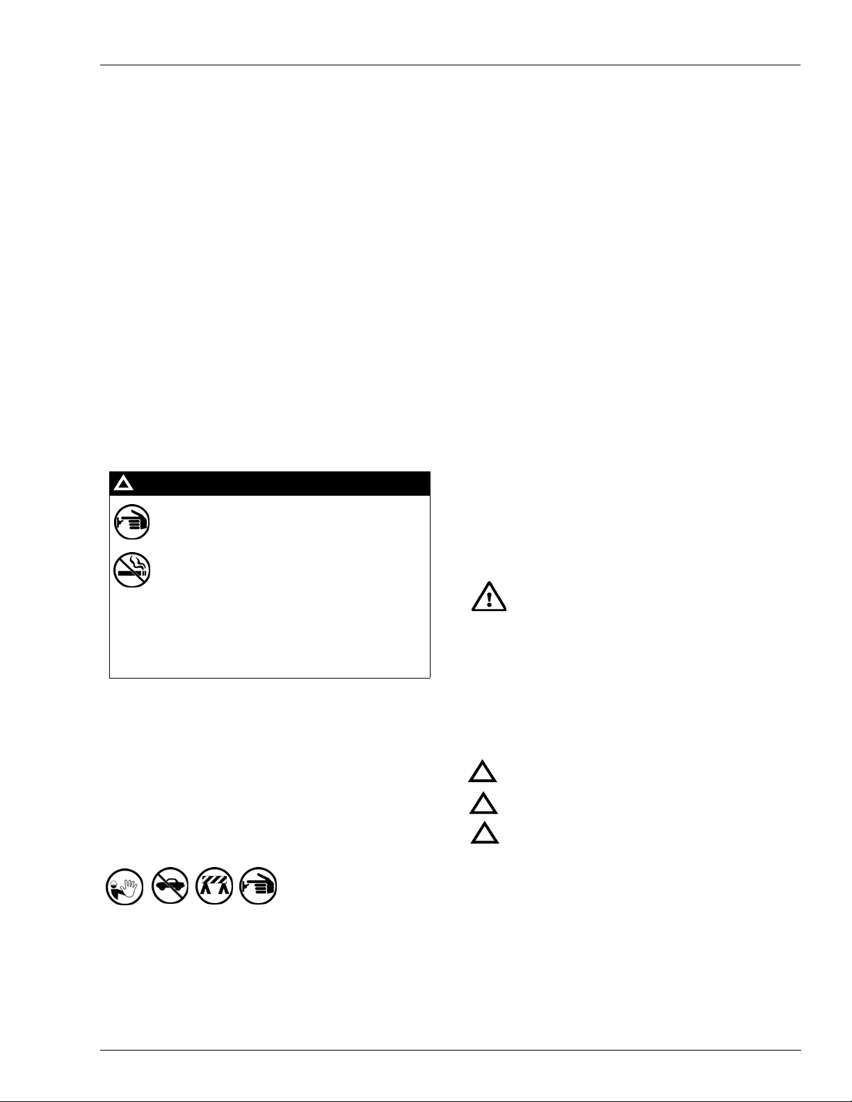
Safety Symbols and Warning Words
This section provides important information about warning
symbols and boxes.
Alert Symbol
You must use the TOTAL ELECTRICAL SHUTOFF in the case of an emergency and not the
console’s ALL STOP and PUMP STOP or
similar keys.
Total Electrical Shut-Off Before Access
Any procedure that requires access to electrical components
or the electronics of the dispenser requires total electrical
shut off of that unit. Understand the function and location of
this switch or circuit breaker before inspecting, installing,
maintaining, or servicing Gasboy equipment.
Evacuating, Barricading and Shutting Off
Any procedure that requires access to the pump/dispenser or
STPs requires the following actions:
• An evacuation of all unauthorized persons and vehicl es
from the work area
• Use of safety tape, cones or barricades at the affected
unit(s)
• A total electrical shut-off of the affected unit(s)
This safety alert symbol is used in this manual and
on warning labels to alert you to a precaution which must be
followed to prevent potential personal safety hazards. Obey
safety directives that follow this symbol to avoid possible
injury or death.
Signal Words
These signal words used in this manual and on warning
labels tell you the seriousness of particular safety hazards.
The precautions below must be followed to prevent death,
injury or damage to the equipment:
DANGER: Alerts you to a hazard or unsafe practice
!
which will result in death or serious injury.
WARNING: Alerts you to a hazard or unsafe practice
!
that could result in death or serious injury.
CAUTION with Alert symbol: Designates a hazard or
!
unsafe practice which may result in minor injury.
CAUTION without Alert symbol: Designates a hazard
or unsafe practice which may result in property or
equipment damage.
Working With Fuels and Electrical Energy
Prevent Explosions and Fires
Fuels and their vapors will explode or burn, if ignited. Spilled
or leaking fuels cause vapors. Even filling customer tanks will
cause potentially dangerous vapors in the vicinity of the
dispenser or island.
MDE-4864 Gasboy® 9820 Pump Interface Kit Installation Instructions · October 2009 Page 3
Page 4

Important Safety Information
No Open Fire
Open flames from matches, lighters, welding
torches or other sources can ignite fuels and their vapors.
No Sparks - No Smoking
Sparks from starting vehicles, starting or using power tools,
burning cigarettes, cigars or pipes can also ignite fuels and
their vapors. Static electricity, including an electrostatic
charge on your body, can cause a spark sufficient to ignite
fuel vapors. Every time you get out of a vehicle, touch the
metal of your vehicle, to discharge any electrostatic charge
before you approach the dispenser island.
Working Alone
It is highly recommended that someone who is capable of
rendering first aid be present during servicing. Familiarize
yourself with Cardiopulmonary Resuscitation (CPR) methods,
if you work with or around high voltages. This information is
available from the American Red Cross. Always advise the
station personnel about where you will be working, and
caution them not to activate power while you are working on
the equipment. Use the OSHA Lockout/ Tagout procedures. If
you are not familiar with this requirement, refer to this
information in the service manual and OSHA documentation.
Working With Electricity Safely
Ensure that you use safe and established practices in
working with electrical devices. Poorly wired devices may
cause a fire, explosion or electrical shock. Ensure that
grounding connections are properly made. Take care that
sealing devices and compounds are in place. Ensure that you
do not pinch wires when replacing covers. Follow OSHA
Lockout/T agout requirements. Station employees and service
contractors need to understand and comply with this program
completely to ensure safety while the equipment is down.
Hazardous Materials
Some materials present inside electronic enclosures may
present a health hazard if not handled correctly. Ensure that
you clean hands after handling equipment. Do not place any
equipment in the mouth.
!
WARNING
The pump/dispenser contains a chemical known to the
State of California to cause cancer.
In an Emergency
Inform Emergency Personnel
Compile the following information and inform emergency
personnel:
• Location of accident (for example, address, front/back of
building, and so on)
• Nature of accident (for example, possible heart attack, run
over by car, burns, and so on)
• Age of victim (for example, baby, teenager, middle-age,
elderly)
• Whether or not victim has received first aid (for example,
stopped bleeding by pressure, and so on)
• Whether or not a victim has vomited (for example, if
swallowed or inhaled something, and so on)
WARNING
!
Gasoline ingested may cause unconsciousness
and burns to internal organs.
Do not induce vomiting.
Keep airway open.
Oxygen may be needed at scene.
Seek medical advice immediately.
WARNING
!
Gasoline inhaled may cause unconsciousness
and burns to lips, mouth and lungs.
Keep airway open.
Seek medical advice immediately.
WARNING
!
Gasoline spilled in eyes may cause burns to eye
tissue.
Irrigate eyes with water for approximately 15
minutes.
Seek medical advice immediately.
WARNING
!
Gasoline spilled on skin may cause burns.
Wash area thoroughly with clear water.
Seek medical advice immediately.
IMPORTANT: Oxygen may be needed at scene if gasoline
has been ingested or inhaled. Seek medical advice
immediately.
WARNING
!
Lockout/Tagout
Lockout/Tagout covers servicing and maintenance of
The pump/dispenser contains a chemical known to the
State of California to cause birth defects or other
reproductive harm.
machines and equipment in which the unexpected
energization or start-up of the machine(s) or equipment or
release of stored energy could cause injury to employees or
personnel. Lockout/Tagout applies to all mechanical,
hydraulic, chemical or other energy, but does not cover
electrical hazards. Subpart S of 29 CFR Part 1910 - Electrical
Hazards, 29 CFR Part 1910.333 contains specific Lockout/
Tagout provision for electrical hazards.
Page 4 MDE-4864 Gasboy® 9820 Pump Interface Kit Installation Instructions · October 2009
Page 5

Installation of the Gasboy 9820 Pump Interface Kit
Installation of the Gasboy 9820 Pump Interface Kit
Installing this kit involves DC wiring to the Fuel Management System. Refer to MDE-4567
9120K & 9820K Series AST Pumps Installation and Operation Manual, and your Fuel
Management System Installation Manual before proceeding.
To install the Gasboy 9820 Pump Interface Kit, proceed as follows:
1 Turn off the circuit breakers that supply power to the MICRO and PUMP feeds.
2 Unlock the door and loosen the two screws. Tilt the top of the door out, then lift up to remove
it.
Figure 1: Removing the Door
Loosen the Screws
Unlock
the
Door
MDE-4864 Gasboy® 9820 Pump Interface Kit Installation Instructions · October 2009 Page 5
Page 6

Installation of the Gasboy 9820 Pump Interface Kit
3 Loosen the two screws located on the left and right door support brackets and pivot the
Display Assembly down.
Figure 2: Relocating the Display Assembly
Loosen
the
Screws
Tag the
Wires
4 Note down the wiring or tag all the wires that are connected to the terminal blocks. Remove all
the wires from the terminal blocks.
5 If the model 9820 Pump contains a battery-backed power supply, pull the connector off P1 on
the power supply. After a few seconds, reconnect P1.
6 Remove the 9820 Chassis from the cabinet.
7 Install the PC Board using the #6-32 hardware.
Figure 3: Installing the PC Board
Cable
#6-32 Hardware
PC Board
CHASSIS TOP VIEW
Page 6 MDE-4864 Gasboy® 9820 Pump Interface Kit Installation Instructions · October 2009
Page 7

Installation of the Gasboy 9820 Pump Interface Kit
8 Feed the connector end of the cable into the round terminal bracket mounting hole at the
bottom-right of the chassis. Position the terminal block with the red wire in position 1. Secure
the terminal block using the #8-32 hardware.
Figure 4: Installing the Terminal Block
Chassis
Cable
#8-32 Hardware
9 Carefully route the cable and install the connector on P1 of the I/F PC Board.
10 Return the chassis to the cabinet.
11 Reconnect all the wiring.
12 Connect the new field wiring to the new terminal block according to the MDE-4567 9120K &
9820K Series AST Pumps Installation and Operation Manual.
13 Turn on the MICRO and FEED circuit breakers.
MDE-4864 Gasboy® 9820 Pump Interface Kit Installation Instructions · October 2009 Page 7
Page 8

Pulse-out I/F Board (M06587A001) Jumper Settings
Pulse-out I/F Board (M06587A001) Jumper Settings
Jumpers JP1, JP2, and JP3
This board assembly can be configured for use in one of the following pump/dispenser
configurations:
• Dual-channel, Single-hose Pulse-out I/F (see Figure 5 on page 9)
• Single-channel, Dual/Single-hose Pulse-out I/F (Refer to MDE-4567 9120K & 9820K
Series AST Pumps Installation and Operation Manual for the wiring diagram, for models
equipped with the old CPU. For models with the new CPU, refer to MDE-4652 Atlas 9800
Electronics Field Installation Instructions).
The chart below shows the jumper settings and wires that need to be connected in the Junction
box, based on the configuration.
Check JP1 - JP3 jumpers and change them, if necessary. The jumper settings must be changed
only when power to the pump/dispenser is removed, to protect the circuit that they are
connected to.
In the model 9820 Pump, the P3 Connector is not connected.
Jumper Settings
Single-channel, Dual/Single-hose Pulse-out I/F
(Default Setting) Dual-channel, Single-hose Pulse-out I/F
Wire Color JP1 Position 1
JP2 Position 1
JP3 Open
Red Pulse-out Pulse-out A
Green No Connection Pulse-out B
White Return Return A
Black No Connection Return B
JP1 Position 2
JP2 Position 2
JP3 Open
Page 8 MDE-4864 Gasboy® 9820 Pump Interface Kit Installation Instructions · October 2009
Page 9

Jumpers JP4 and JP5
When this board is used in a model 9820 Pump/Dispenser, jumpers JP4 and JP5 are set to the
Q/A position.
Figure 5 illustrates the proper output for using a Pump I/F Board (M0 6587A001), ju mpered to
provide two isolated pulse outputs from a single pulser (C07355 kits).
Figure 5: Dual-channel, Single-hose Pulse-out I/F
REMOTE REGISTER
Pulse-out I/F Board (M06587A001) Jumper Settings
Note: 1) All wiring and conduit runs must conform with all building/fire codes, all Federal,
State, and Local codes, National Electrical Code, (NFPA 70), NFPA 30, and
Automotive and Marine Service Station Code (NFPA 30A) codes and regulations.
Canadian users must also comply with the Canadian Electrical Code.
2) Refer to MDE-4567 9120K & 9820K Series AST Pumps Installation and Operation
Manual or MDE-4652 Atlas 9800 Electronics Field Installation Instructions for
complete installation instructions.
MDE-4864 Gasboy® 9820 Pump Interface Kit Installation Instructions · October 2009 Page 9
Page 10

Atlas™ and Gasboy® are registered trademarks of Gasboy Inc. Phillips® is a registered trademark of The Phillips Screw Co.
© 2009 GASBOY
7300 West Friendly Avenue · Post Office Box 22087
Greensboro, North Carolina 27420
Phone 1-800-444-5529 · http://www.gasboy.com · Printed in the U.S.A.
MDE-4864 Gasboy® 9820 Pump Interface Kit Installation Instructions · October 2009
 Loading...