

Page 1

Series 9800Q Pumps and Dispensers
Installation/Operation Manual
MDE-4340A
Page 2

Computer Programs and Documentation
Federal Communications Commission (FCC) Warning
All Gasboy computer programs (including software on diskettes and within memory chips) and documentation are copyrighted by, and shall remain the property of, Gasboy. Such
computer programs and documents may also contain trade secret information. The duplication, disclosure, modification, or unauthorized use of computer programs or
documentation is strictly prohibited, unless otherwise licensed by Gasboy.
This equipment has been tested and found to comply with the limits for a Class A digital device pursuant to Part 15 of the FCC Rules. These limits are designed to provide
reasonable protection against harmful interference when the equipment is operated in a commercial environment. This equipment generates, uses, and can radiate radio frequency
energy, and if not installed and used in accordance with the instruction manual, may cause harmful interference to radio communications. Operation of this equipment in a
residential area is likely to cause harmful interference in which case the user will be required to correct the interference at his own expense. Changes or modifications not expressly
approved by the manufacturer could void the user’s authority to operate this equipment.
Approvals
Gasboy, Greensboro, is an ISO 9001:2000 registered facility.
Underwriters Laboratories (UL):
UL File# Products listed with UL
MH4314
MH6418
MH7404
MH10581 Key control unit, Model GKE-B Series
All dispensers and self-contained pumping
units
Power operated Transfer Pump Models 25,
25C, 26, 27, 28, 72, 72S, 72SP, 72X, 73 and
1820
Hand operated Transfer Pump Models 1230
Series, 1243 Series, 1520 and 1720 Series
Card reader terminals, Models 1000, 1000P
Site controller, Model 2000S CFN Series
Data entry terminals, Model TPK-900 Series
Fuel Point Reader System
New York City Fire Department (NYFD):
NYFD C of A # Product
4823 9100K, 9140K, 9152K, 9153K,
4997 9822K, 9823K, 9822A, 9823A
5046 9100K, 9140K, 9152K, 9153K,
9800K, 9840K, 9850K, 9852K,
9853K, 9140, 9100A, 9140A, 9152A,
9153A, 9800A, 9840A, 9850A,
9852A, 9853A, 9100
9800K, 9840K, 9852K, 9853K,
9100Q, 9140Q, 9152Q, 9153Q,
9800Q, 9840Q, 9852Q, 9853Q, 9850Q
National Conference of Weights and Measures (NCWM) - Certificate of Compliance (CoC):
Gasboy pumps and dispensers are evaluated by NCWM under the National Type Evaluation Program (NTEP). NCWM has issued the following CoC:
CoC# Product Model # CoC# Product Model # CoC# Product Model #
95-179A2 Dispenser
95-136A5 Dispenser 9800 Series 91-057A3 Controller
9100 Retail Series, 8700
Series, 9700 Series
91-019A2 Dispenser
9100 Commercial
Series
1000 Series FMS,
2000S-CFN Series
California Air Resources Board (CARB):
Executive Order # Product
G-70-52-AM Balance Vapor Recovery
G-70-150-AE VaporVac
Patents
Gasboy products are manufactured or sold under one or more of the following US patents:
Dispensers
5,257,720
Point of Sale/Back Office Equipment
D335,673
Trademarks
Non-registered trademarks
Atlas™
Consola™
Infinity™
Registered trademarks
ASTRA
Fuel Point
Gasboy
Keytrol
Slimline
Additional US and foreign patents pending.
®
®
®
®
®
Additional US and foreign trademarks pending.
Other brand or product names shown may be
trademarks or registered trademarks of their
respective holders.
This document is subject to change without notice. · For information regarding Gasboy Literature, call (336) 547-5661
E-mail: literature@gasboy.com · Internet: http://www.gasboy.com
© 2006 GASBOY · All Rights Reserved
Page 3

Table of Contents
Table of Contents
1 – Introduction 1-1
Purpose . . . . . . . . . . . . . . . . . . . . . . . . . . . . . . . . . . . . . . . . . . . . . . . . . . . .1-1
General Description . . . . . . . . . . . . . . . . . . . . . . . . . . . . . . . . . . . . . . . . . . .1-1
2 – Important Safety Information 2-1
In an Emergency . . . . . . . . . . . . . . . . . . . . . . . . . . . . . . . . . . . . . . . . . . . . .2-3
3 – Installation 3-1
Installation Precautions . . . . . . . . . . . . . . . . . . . . . . . . . . . . . . . . . . . . . . . .3-1
Foundation . . . . . . . . . . . . . . . . . . . . . . . . . . . . . . . . . . . . . . . . . . . . . . . . . .3-2
Suction Pump. . . . . . . . . . . . . . . . . . . . . . . . . . . . . . . . . . . . . . . . . . . . . . . .3-3
Remote Dispenser . . . . . . . . . . . . . . . . . . . . . . . . . . . . . . . . . . . . . . . . . . . .3-3
Supply Line . . . . . . . . . . . . . . . . . . . . . . . . . . . . . . . . . . . . . . . . . . . . . . . . .3-4
Nozzle, Hose, and Accessories . . . . . . . . . . . . . . . . . . . . . . . . . . . . . . . . . .3-5
4 – Control Lines 4-1
Purpose . . . . . . . . . . . . . . . . . . . . . . . . . . . . . . . . . . . . . . . . . . . . . . . . . . . .4-1
Ground . . . . . . . . . . . . . . . . . . . . . . . . . . . . . . . . . . . . . . . . . . . . . . . . . . . . .4-1
Micro Feed . . . . . . . . . . . . . . . . . . . . . . . . . . . . . . . . . . . . . . . . . . . . . . . . . .4-1
Micro Neutral . . . . . . . . . . . . . . . . . . . . . . . . . . . . . . . . . . . . . . . . . . . . . . . .4-2
Control/Pump Motor Feed . . . . . . . . . . . . . . . . . . . . . . . . . . . . . . . . . . . . . .4-2
External Valve . . . . . . . . . . . . . . . . . . . . . . . . . . . . . . . . . . . . . . . . . . . . . . .4-2
Neutral Feed . . . . . . . . . . . . . . . . . . . . . . . . . . . . . . . . . . . . . . . . . . . . . . . .4-2
Control/Submersible Feed (Control/SubM Feed) . . . . . . . . . . . . . . . . . . . . .4-2
Submersible Starter Drive (SubM Starter Drive) . . . . . . . . . . . . . . . . . . . . .4-3
Submersible Pump Drive (SubM Pump Drive). . . . . . . . . . . . . . . . . . . . . . .4-4
Reset Complete (Switch Detect)/Slow Flow. . . . . . . . . . . . . . . . . . . . . . . . .4-4
Fast Flow . . . . . . . . . . . . . . . . . . . . . . . . . . . . . . . . . . . . . . . . . . . . . . . . . . .4-4
Phase 2 Feed. . . . . . . . . . . . . . . . . . . . . . . . . . . . . . . . . . . . . . . . . . . . . . . .4-5
Slow/Fast Satellite Returns . . . . . . . . . . . . . . . . . . . . . . . . . . . . . . . . . . . . .4-5
Light Feed . . . . . . . . . . . . . . . . . . . . . . . . . . . . . . . . . . . . . . . . . . . . . . . . . .4-5
Light Neutral. . . . . . . . . . . . . . . . . . . . . . . . . . . . . . . . . . . . . . . . . . . . . . . . .4-5
Pulser . . . . . . . . . . . . . . . . . . . . . . . . . . . . . . . . . . . . . . . . . . . . . . . . . . . . . .4-6
RS-485 . . . . . . . . . . . . . . . . . . . . . . . . . . . . . . . . . . . . . . . . . . . . . . . . . . . . .4-6
RS-232 and RS-422. . . . . . . . . . . . . . . . . . . . . . . . . . . . . . . . . . . . . . . . . . .4-6
5 – Wiring 5-1
Wiring Precautions . . . . . . . . . . . . . . . . . . . . . . . . . . . . . . . . . . . . . . . . . . . .5-1
Ground . . . . . . . . . . . . . . . . . . . . . . . . . . . . . . . . . . . . . . . . . . . . . . . . . . . . .5-2
Circuit Breakers . . . . . . . . . . . . . . . . . . . . . . . . . . . . . . . . . . . . . . . . . . . . . .5-2
The Pump Motor . . . . . . . . . . . . . . . . . . . . . . . . . . . . . . . . . . . . . . . . . . . . .5-2
Motor Amp Ratings . . . . . . . . . . . . . . . . . . . . . . . . . . . . . . . . . . . . . . . . . . .5-3
Wire Size . . . . . . . . . . . . . . . . . . . . . . . . . . . . . . . . . . . . . . . . . . . . . . . . . . .5-3
Conduit. . . . . . . . . . . . . . . . . . . . . . . . . . . . . . . . . . . . . . . . . . . . . . . . . . . . .5-4
Pulse Output or RS-485 Wiring . . . . . . . . . . . . . . . . . . . . . . . . . . . . . . . . . .5-5
Wiring Diagrams. . . . . . . . . . . . . . . . . . . . . . . . . . . . . . . . . . . . . . . . . . . . . .5-7
MDE-4340A Series 9800Q Pumps and Dispensers Installation/Operation Manual · January 2006 Page i
Page 4

Table of Contents
6 – Pump/Remote Dispenser Operation 6-1
Overview . . . . . . . . . . . . . . . . . . . . . . . . . . . . . . . . . . . . . . . . . . . . . . . . . . . 6-1
Electronic Component Access . . . . . . . . . . . . . . . . . . . . . . . . . . . . . . . . . . 6-1
CPU Switch Settings . . . . . . . . . . . . . . . . . . . . . . . . . . . . . . . . . . . . . . . . . . 6-2
SW1 . . . . . . . . . . . . . . . . . . . . . . . . . . . . . . . . . . . . . . . . . . . . . . . . . . . . . . 6-3
SW2 . . . . . . . . . . . . . . . . . . . . . . . . . . . . . . . . . . . . . . . . . . . . . . . . . . . . . . 6-5
Pulser Output Rate Switches . . . . . . . . . . . . . . . . . . . . . . . . . . . . . . . . . . . 6-5
Timeout Switch . . . . . . . . . . . . . . . . . . . . . . . . . . . . . . . . . . . . . . . . . . . . . . 6-6
ATC Information Sheet . . . . . . . . . . . . . . . . . . . . . . . . . . . . . . . . . . . . . . . . 6-6
Battery Back-Up Power Supply. . . . . . . . . . . . . . . . . . . . . . . . . . . . . . . . . . 6-7
View/Reset Totalizers . . . . . . . . . . . . . . . . . . . . . . . . . . . . . . . . . . . . . . . . . 6-8
Operating Sequence . . . . . . . . . . . . . . . . . . . . . . . . . . . . . . . . . . . . . . . . . . 6-9
Standalone Mode Error Handling . . . . . . . . . . . . . . . . . . . . . . . . . . . . . . . 6-10
7 – Start-Up and Test 7-1
Installation Completion Checklist . . . . . . . . . . . . . . . . . . . . . . . . . . . . . . . . 7-1
Start-Up. . . . . . . . . . . . . . . . . . . . . . . . . . . . . . . . . . . . . . . . . . . . . . . . . . . . 7-1
Post Start-Up Tests. . . . . . . . . . . . . . . . . . . . . . . . . . . . . . . . . . . . . . . . . . . 7-2
8 – Preventive Maintenance 8-1
General . . . . . . . . . . . . . . . . . . . . . . . . . . . . . . . . . . . . . . . . . . . . . . . . . . . . 8-1
Hints for Better Pump Performance . . . . . . . . . . . . . . . . . . . . . . . . . . . . . . 8-1
Preventive Maintenance Check List . . . . . . . . . . . . . . . . . . . . . . . . . . . . . . 8-2
Page ii MDE-4340A Series 9800Q Pumps and Dispensers Installation/Operation Manual · January 2006
Page 5

1 – Introduction
Purpose
The Gasboy Series 9800Q Pumps and Dispensers Installation/Operation Manual is provided to
assist the installer in installing and operating the unit. This manual should be supplied to the
electrician prior to the installation of conduit and wiring to ensure that the Series 9800Q
dispensing unit is installed properly. Faulty installations are the major cause of unit
malfunctions. The unit must be installed and operated as described in this manual to ensure the
reliability and proper operation of the Series 9800Q dispensing unit. In addition to installation
information, this manual contains warnings, safeguards and procedures on the use and care of
the Series 9800Q pumps and remote dispensers. Ensure that you leave this manual with the
pump/remote dispenser owner after the installation is complete.
Note: Customers and installers having any questions pertaining to the installation should
contact their Gasboy distributor.
This manual provides instructions for safely operating, programming, and maintaining the
Atlas™ Fuel Systems pumps/dispensers.
Introduction
General Description
The Gasboy Series 9800Q dispensing units are UL®-listed and are available in a self-contained
(suction pump) package or in a remote-controlled (remote dispenser) package. Both packages
offer a variety of models which are available as single hose outlets or dual hose outlets (with
single or dual product capability). The self-contained models are available in standard speed
(up to 15 GPM/56 LPM) or in high speed (up to 22 GPM/83 LPM). The self-contained
package also boasts a single hose model with high capacity speed (up to 26 GPM/98 LPM), a
dual flow unit (up to 40 GPM/151 LPM) and a high flow unit (up to 50 GPM/189LPM). The
rate of delivery for the remote-controlled packages will vary according to the size of the
submersible pump. The delivery rate of both packages will also vary depending upon
installation conditions and added accessories.
The Series 9800Q offers the following features:
Standard
Speed
Models
High Speed
Models
Super
Speed
Model (up to
40 GPM)
Suction Pumps Remote Dispensers Features
9852Q
9852QTW1
9852QTW2
9853Q
9853QTW2
9853QTW1M
9840Q 9840QX Inlet: 2" NPT
9852QX
9852QXTW1
9852QXTW2
9853QX
9853QXTW1
9853QXTW2
Inlet: 1-1/2" NPT
Discharge: 3/4" NPT (female threads)
Motor: 3/4 HP continuous duty
Valves (when used): 3/4"
Inlet: 1-1/2" NPT
Discharge: 1" NPT (female threads)
Motor: 3/4 HP continuous duty
Valves (when used): 1"
Discharge: 1-1/4" NPT (female threads)
with 1-1/4"x1" reducer bushing
Motor: two 3/4 HP continuous duty
Valves (when used): 1-1/2"
MDE-4340A Series 9800Q Pumps and Dispensers Installation/Operation Manual · January 2006 Page 1-1
Page 6

Introduction
All models of the Series 9800Q offer electronic registration of the quantity dispensed. The
following lists detail the standard features and the available options found in the 9800Q:
Standard Features
• Cabinet: Painted black top and sides, white front and rear doors and white dial enclosures.
Dimensions are 29-1/16"W, 18-3/8"D, 52-5/8"H.
• Meter: Four piston, positive displacement.
• Pump: Belt-driven, positive-displacement rotary vane with an 80 mesh (300 micron)
strainer and integral air separation.
• Motor: (See chart earlier in this section).
• Reset Complete (switch detect) output which allows monitoring of the unit's operation
when it is connected to an automated Fuel Management System.
• Dual stage solenoid valves (standard only on remote dispensers).
• Island-oriented nozzle boots.
• UL-listed hose assembly, 3/4"x 12' for standard speed; 1" x 12' for high and super speed.
• Designed to support UL-listed Interchangeable service station nozzles (not included).
• Hose hangers.
• Dual phase, error-checking pulsers.
• Non-computing register (volume only) displays, 1" backlighted LCD displays. Records up
to 999.000 gallons.
• Electronic totalizers, viewed from the back side of the unit, records, up to 999,999 liters or
gallons. Battery-backed, resettable.
• Fluids: Gasoline, diesel, kerosene. Not suitable for methanol/ethanol blends.
• Agencies: UL, CUL, W&M.
Optional accessories
• Pulser output drive lines (open collector) capable of driving 1, 10, 100, 250, or 500 pulses
per unit (gallons) or 1, 10, or 100 pulses per unit (liters)
• Inlet check valve
• Internal hose retractor
• Internal fuel filter adapter
• Solenoid valve
• Satellite piping
• Stainless steel exterior or special painting
• 230 or 380 VAC operation
• Liter registration
• Listed automatic nozzles
• Special lengths of hose
• Listed swivels and breakaways
• Spin-on filter elements
• Listed emergency shutoff valves
• Listed pressure regulating valve for aboveground tank applications used with suction
pumps
•Front load nozzle arrangement
• TopKAT mounting
• Battery-backup for electronic display
• Export packaging
• Automatic Temperature Compensation (ATC)
• RS-485 communication for direct connect to Gasboy CFN or TopKAT equipment
Page 1 -2 MDE-4340A Series 9800Q Pumps and Dispensers Installation/Operation Manual · January 2006
Page 7

Introduction
• Submersible drive relays capable of handling 3/4 HP at 115 VAC or 1-1/2 HP at 230 VAC
• Fluorescent lighting for the faceplate and brand panel
Related Documentation
Document
Number
035286 215A/216A Installation /Operation Manual Gasboy Commercial & Retail Pumps
C01918 CFN Site Controller II Installation Manual. Gasboy Fuel Management Products
C35628 Fuel Point Reader Installation and Retrofit Manual Gasboy Fuel Management Products
C35963 CFN Series Islander II Installation Manual Gasboy Fuel Management Products
MDE-4298 CFN Site Controller I Installation Manual Gasboy Fuel Management Products
MDE-4344 Series 1000 Installation Manual Gasboy Fuel Management Products
Document Title GOLD Library
Acronym Table
The following table contains a list of acronyms used in this manual.
Note: Refer the glossary section for more detailed definitions.
Acronym Definition
AC or ac Alternating Current
ASC Authorized Service Contractor
AWG American Wire Gauge
CFR Code of Federal Regulations
CPR Cardiopulmonary Resuscitation
CPU Central Processing Unit
CSA Canadian Standards Association (Canadian equivalent of UL)
DC (or dc) Direct Current
DIP Dual In-line Package
DLT Displaying Last Transaction
FMS Fuel Management System
FPR Fuel Point Reader
GPM (or gpm) Gallons Per Minute
HP Horse Power
IFSF International Forecourt Standards Forum
LPM Liters Per Minute
MOC Major Oil Company
NEC National Electrical Code
NFPA National Fire Protection Association
OSHA Occupational Safety and Health Association
PCB Printed Circuit Boards (preferred term: board)
POS Point Of Sale
PPG Pulses Per Gallon
PPL Pulses Per Liter
PPP Programmable Pump Preset
RS Request-to-Send (modem application)
MDE-4340A Series 9800Q Pumps and Dispensers Installation/Operation Manual · January 2006 Page 1-3
Page 8

Introduction
Acronym Definition
RS-485 Recommended Standard number 485 [from Electronic
Industry Association (EIA)]
STP Submerged Turbine Pump
UL Underwriters Laboratory
VAC ( o r vac) Volts Alternating Current
Page 1 -4 MDE-4340A Series 9800Q Pumps and Dispensers Installation/Operation Manual · January 2006
Page 9

2 – Important Safety Information
This section introduces the hazards and safety precautions
associated with installing, inspecting, maintaining or servicing
this product. Before performing any task on this product, read
this safety information and the applicable sections in this
manual, where additional hazards and safety precautions for
your task will be found. Fire, explosion, electrical shock or
pressure release could occur and cause death or serious
injury if these safe service procedures are not followed.
Preliminary Precautions
You are working in a potentially dangerous environment of
flammable fuels, vapors, and high voltage or pressures. Only
trained or authorized individuals knowledgeable in the related
procedures should install, inspect, maintain or service this
equipment.
Emergency Total Electrical Shut-Off
The first and most important information you must know is
how to stop all fuel flow to the pump and island. Locate the
switch or circuit breakers that shut-off all power to all fueling
equipment, dispensing devices, and submerged turbine
pumps (STPs).
!
WARNING
!
The EMERGENCY STOP, ALL STOP, and
PUMP STOP buttons at the cashier’s station
WILL NOT shut off electrical power to the
pump/dispenser.
Total Electrical Shut-Off Before Access
Any procedure requiring access to electrical components or
the electronics of the dispenser requires total electrical shutoff of that unit. Know the function and location of this switch
or circuit breaker before inspecting, installing, maintaining, or
servicing Gasboy equipment.
Evacuation, Barricading and Shut-Off
Any procedures requiring accessing the pump/dispenser or
STPs requires the following three actions:
This means that even if you activate these
stops, fuel may continue to flow uncontrolled.
You must use the TOTAL ELECTRICAL SHUTOFF in the case of an emergency and not only
these cashier station “stops.”
Read the Manual
Read, understand and follow this manual and any other
labels or related materials supplied with this equipment. If you
do not understand a procedure, call the Gasboy Customer
Service at 1-800-444-5579, Tech Support 1-800-444-5529. It
is imperative to your safety and the safety of others to
understand the procedures before beginning work.
Follow the Regulations
There is applicable information in NFPA 30A; Automotive and
Marine Service Code, NFPA 70; National Electrical Code (NEC),
OSHA regulations and federal, state, and local codes which
must be followed. Failure to install, inspect, maintain or
service this equipment in accordance with these codes,
regulations and standards may lead to legal citations with
penalties or affect the safe use and operation of the
equipment.
Replacement Parts
Use only genuine Gasboy replacement parts and retrofit kits
on your pump/dispenser. Using parts other than genuine
Gasboy replacement parts could create a safety hazard and
violate local regulations.
Safety Symbols and Warning Words
This section provides important information about warning
symbols and boxes.
Alert Symbol
This safety alert symbol is used in this manual and
on warning labels to alert you to a precaution which must be
followed to prevent potential personal safety hazards. Obey
safety directives that follow this symbol to avoid possible
injury or death.
Signal Words
These signal words used in this manual and on warning
labels tell you the seriousness of particular safety hazards.
The precautions that follow must be followed to prevent
death, injury or damage to the equipment
DANGER - This signal word is used to alert you to a
hazard to unsafe practice which will result in death or
serious injury
!
WARNING - This alerts you to a hazard or unsafe
practice that could result in death or serious injury.
!
CAUTION with Alert symbol - This signal word
designates a hazard or unsafe practice which may
!
result in minor injury.
CAUTION without Alert symbol - When used by itself,
CAUTION designates a hazard or unsafe practice
which may result in property or equipment damage.
- An evacuation of all unauthorized persons and vehicles
using safety tape, cones or barricades to the effected units
- A total electrical shut-off of that unit
MDE-4340A Series 9800Q Pumps and Dispensers Installation/Operation Manual · January 2006 Page 2-1
Working With Fuels and Electrical Energy
Prevent Explosions and Fires
Fuels and their vapors will become explosive if ignited.
Spilled or leaking fuels cause vapors. Even filling customer
tanks will cause explosive vapors in the vicinity of dispenser
or island.
Page 10

No Open Flames
Emergency First Aid
Open flames from matches, lighters, welding torches
or other sources can ignite fuels and their vapors.
No Sparks - No Smoking
Sparks from starting vehicles, starting or using power tools,
burning cigarettes, cigars or pipes can also ignite fuels and
their vapors. Static electricity, including an electrostatic
charge on your body, can cause a spark sufficient to ignite
fuels and their vapors. After getting out of a vehicle, touch the
metal of your vehicle to discharge any electrostatic charge
before you approach the dispenser island.
Working Alone
It is highly recommended that someone who is capable of
rendering first aid be present during servicing. Be familiar
with Cardiopulmonary Resuscitation (CPR) methods if you
are working with or around high voltages. This information is
available from the American Red Cross. Always advise the
station personnel about where you will be working, and
caution them not to activate power while you are working on
the equipment. Use the OSHA tag out and lock out
procedures. If you are not familiar with this requirement, refer
to information in the service manual and OSHA
documentation.
Working With Electricity Safely
Be sure to use safe and established practices in working with
electrical devices. Poorly wired devices may cause a fire,
explosion or electrical shock. Be sure grounding connections
are properly made. Make sure that sealing devices and
compounds are in place. Be sure not to pinch wires when
replacing covers Follow OSHA Lock-Out and Tag-Out
requirements. Station employees and service contractors
need to understand and comply with this program completely
to ensure safety while the equipment is down.
Hazardous Materials
Some materials present inside electronic enclosures may
present a health hazard if not handled correctly. Be sure to
clean hands after handling equipment. Do not place any
equipment in mouth.
!
WARNING
This area contains a chemical known to the State of
California to cause cancer.
WARNING
!
This area contains a chemical known to the State of
California to cause birth defects or other reproductive
harm.
IMPORTANT: Oxygen may be needed at scene if gasoline
has been ingested or inhaled. Seek medical advice
immediately.
Informing Emergency Personnel
• Compile the following information for emergency
personnel:
• Location of accident (for example, address, front/back of
building, and so on.)
• Nature of accident (for example, possible heart attack, run
over by car, burns, and so on.)
• Age of victim (for example, baby, teenager, middle-age,
elderly)
• Whether or not victim has received first aid (for example,
stopped bleeding by pressure, and so on.)
• Whether or not a victim has vomited (for example, if
swallowed or inhaled something, and so on.)
WARNING
!
Gasoline ingested may cause unconsciousness
and burns to internal organs.
Do not induce vomiting.
Keep airway open.
Oxygen may be needed at scene.
Seek medical advice immediately.
WARNING
!
Gasoline inhaled may cause unconsciousness
and burns to lips, mouth and lungs.
Keep airway open.
Seek medical advice immediately.
WARNING
!
Gasoline spilled in eyes may cause burns to eye
tissue.
Irrigate eyes with water for approximately 15
minutes.
Seek medical advice immediately
WARNING
!
Gasoline spilled on skin may cause burns.
Wash area thoroughly with clear/water.
Seek medical advice immediately.
IMPORTANT: Oxygen may be needed at scene if gasoline
has been ingested or inhaled. Seek medical advice
immediately.
Lockout/Tagout
Lockout/Tagout covers servicing and maintenance of
Machines and equipment in which the unexpected
energization or start up of the machine(s) or equipment or
release of stored energy could cause injury to employees or
personnel. Lockout/Tagout applies to all mechanical,
hydraulic, chemical or other energy, but does not cover
electrical hazards. Reference Subpart S of 29 CFR Part 1910
- Electrical Hazards, 29 CFR Part 1910.333 contains specific
Lockout/Tagout provision for electrical hazards.
Page 2-2 MDE-4340A Series 9800Q Pumps and Dispensers Installation/Operation Manual · January 2006
Page 11
In an Emergency
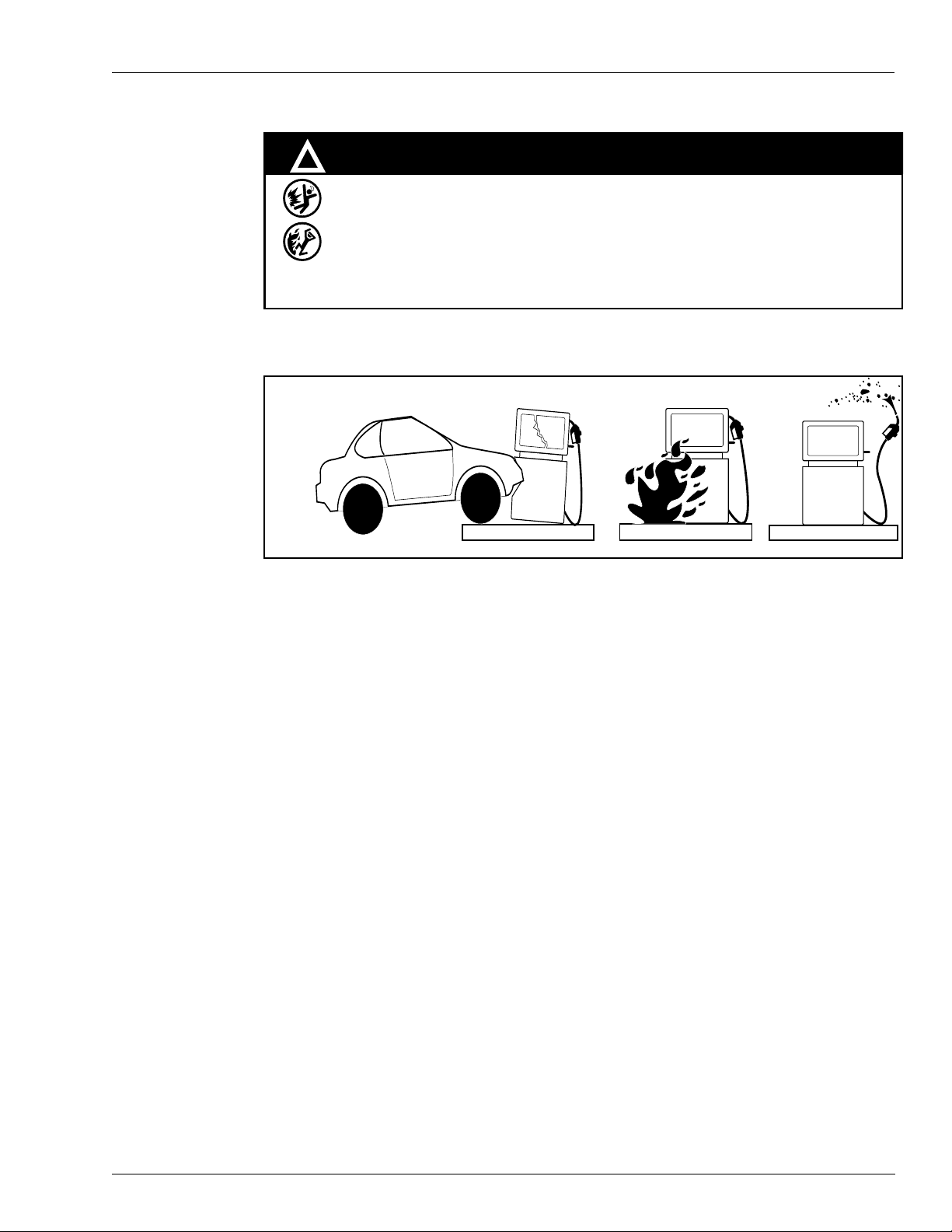
The following actions are recommended regarding these hazards:
WARNING
!
Spilled fuels, accidents involving pumps/dispensers, or uncontrolled fuel flow creates
a serious hazard.
Fire or explosion may result causing serious injury or death.
Follow established emergency procedures.
Collision of Vehicle with Unit Fire at Island Fuel Spill
• Do not go near fuel spill or allow anyone else in the area.
• Use station EMERGENCY CUTOFF immediately. Turn off all system circuit breakers to
the island(s).
• Do not use console E-STOP, ALL STOP keys to shut off power. These keys do not
remove AC power and do not always stop product flow.
• Take precautions to avoid igniting fuel. Do not allow starting of vehicles in the area. No
open flames, smoking or power tools in the area.
• Do not expose yourself to hazardous conditions such as fire, spilled fuel or exposed
wiring.
• Call emergency numbers.
MDE-4340A Series 9800Q Pumps and Dispensers Installation/Operation Manual · January 2006 Page 2-3
Page 12

This page is intentionally left blank.
Page 2-4 MDE-4340A Series 9800Q Pumps and Dispensers Installation/Operation Manual · January 2006
Page 13

3 – Installation
Installation Precautions
All installations must conform with all building/fire codes, all Federal, State, and Local codes,
National Electrical Code, (NFPA 70), NFPA 30, and Automotive and Marine Service Station
Code (NFPA 30A) codes and regulations. Canadian users must also comply with the Canadian
Electrical Code.
Plan your installation carefully. A pump/remote dispenser cannot be expected to work
satisfactorily unless the underground installation is correct. Dispensing troubles, which seem
to be pump-related, are frequently traced to faulty installation. Review the following list of
installation DOs and DON’Ts to avoid potential problems:
1 DO read the Important Safety Information pages at the front of this manual. It contains
important information regarding the safe use of your dispensing equipment.
2 DO install an emergency power cutoff. In addition to circuit breaker requirements of NFPA 70
and NFPA 30A, a single control which simultaneously removes AC power from all site
dispensing equipment is recommended. This control must be readily accessible, clearly
labeled, and in accordance with all local codes.
Installation
3 In a Fuel Management System application, the EMERGENCY STOP and STOP keys on the
console and/or the optional EMERGENCY STOP button on the Island Card Reader do not
remove AC power from equipment and under certain conditions, will not stop product flow.
4 In order to provide the highest level of safety to you, your employees, and customers, we
recommend that all employees be trained as to the location and procedure for turning off
power to the entire system.
5 DO have the pump/remote dispenser installed by a competent installer/electrician.
6 DO install breakaway coupling on discharge hose. If using a high hose retriever, install
breakaway approximately 12" downstream of hose clamp on nozzle side of clamp.
7 DO NOT attempt to wire a pump/remote dispenser without first reviewing the appropriate
wiring diagram and notes. Wiring diagrams contain important restrictions regarding the
connection of additional equipment. Failure to follow the correct wiring diagram may result in
damage to the CPU PCB.
8 DO NOT experiment with a pump if you are not sure the installation is correct.
9 DO NOT overload sub- or main-breaker panels.
10 DO NOT install any underground piping without proper swing joints (Always use shoulder
nipples, never close nipples).
11 DO NOT cover any lines until they have been both air- and liquid-tested.
MDE-4340A Series 9800Q Pumps and Dispensers Installation/Operation Manual · January 2006 Page 3-1
Page 14

Installation
12 DO NOT back-fill the tank or supply line with cinders or ashes. (Back-fill with clean sand,
crushed rock, or pea gravel).
13 DO NOT use black iron pipe or fittings for underground installations. (Use only new
galvanized or fiberglass* pipe and fittings). *Install all fiberglass pipe and fittings according to
manufacturer's specifications and requirements.
14 DO NOT use power line wiring of inadequate capacity. (Use gauge specified by the wiring
diagram or wire chart provided in
15 DO NOT use a circuit breaker of improper size (See “Wiring” on page 5-1).
16 DO NOT install fill pipe to tank where it can be submerged with standing water.
17 DO NOT use the Gasboy fuel dispensing equipment to remove water ballast from the storage
“Wiring” on page 5-1).
tank.
18 DO NOT use gaskets on covers of explosion-proof type boxes. The sealing compound found
around wires at all junction box entrances is a requirement of the National Electrical Code and
should not be disturbed. Ensure that the mating surfaces between the junction box and cover
are free of dirt, debris, nicks, and scratches. Tighten junction box covers before replacing
panels.
Foundation
19 DO NOT use knock-out boxes or flexible conduit for installing this unit. All power and
lighting wires should be run in threaded, rigid, metal conduit. All threaded connections must
be drawn up tight with five (5) threads minimum engagement. Only one opening in the AC
junction box is provided with a plug at the factory. On completion of the installation, it is the
installer's responsibility to ensure that any unused openings are plugged.
When constructing the pump island for the dispensing equipment, be sure to extend the island
excavation beyond the depth of the frost line. Leave open an area from the inside edge of the
unit's base as shown on the specific base layout. Unless required by local regulations, do not
cement the pipes and conduits into the island. The open area within the base will provide
access for future servicing of the fittings, check valve and conduit assemblies. Fill in the
boxed-in section with dry sand to keep condensation in the pump housing to a minimum and to
help prevent fogging of the totalizer window.
Secure the pump/remote dispenser to the island using anchor bolts through the two mounting
holes, which are 13 inches (330mm) apart and are indicated on each base layout by an X. If the
dispensing unit is not securely fastened to the island, supply line leaks at unions and pipe joints
may occur. Use one of two types of bolts to anchor the pump to the island. Use two (2) 1/2" x
5" (13mm x 125mm) machine bolts imbedded in the concrete, or, to meet minimum UL and
API requirements for universal interchangeability of pumps, use two 1/2" x 3 1/2" (13mm x
90mm) lag screws with 2" (51mm) expansion shields.
Page 3-2 MDE-4340A Series 9800Q Pumps and Dispensers Installation/Operation Manual · January 2006
Page 15

Suction Pump
Installation
The pump and the tank should be located close to each other with as few changes in direction
of the supply line, as possible. This reduces the possibility of vaporization (gasoline only),
attains the highest possible flow rate, and results in a lower installation cost. Avoid long
supply lines and excessive vertical lifts. The dynamic lift for this unit is rated at 12 feet (4m)
for gasoline and 13 feet (4m) for diesel and can vary according to conditions of the installation
and fuel temperature.
If a pump is to be used with an above-ground tank, a pressure regulator valve is required on the
suction side of the pump; consult your Gasboy representative for details. The tank should be
free of water and dirt. It is recommended that the tank be pressure tested to verify it is tight.
This type of installation is not recommended for Models 9840Q and 9853QTW1M; consult
your Gasboy representative for details.
Note: The outlet fitting at the top of the float chamber should be connected to drain back to
the storage tank. The pipe size for the return line to the storage tank should be at least
3/8" (10mm).
Remote Dispenser
Locate the remote dispenser and tank with submersible pump as close to each other as possible
to attain minimum possible pressure drop and the highest possible flow rate, consistent with
the pump capacity. Consult the submersible pump manufacturer's recommendations for pipe
sizing and installation instructions pertaining to the model of submersible pump being
installed.
A Listed emergency shut-off valve (OPW 10RUS or equal) must be installed under each
remote dispenser with the shear groove at the same level as the top of the concrete island +
(plus) 1/2" (13mm). The shear valve should be rigidly supported to ensure proper shearing and
closure of the valve in the event that the remote dispenser is dislodged. According to the type
of shear valve, a different supply nipple may be required.
After a shear valve has operated on an emergency basis from fire or mechanical shock, or if it
does not operate correctly when inspected, repairs must be made before putting the remote
dispenser into service.
It is required by the Flammable and Combustible Liquids Code that a leak detector be installed
in the system to prevent underground leaks from going unnoticed.
MDE-4340A Series 9800Q Pumps and Dispensers Installation/Operation Manual · January 2006 Page 3-3
Page 16

Installation
Supply Line
IMPORTANT INFORMATION
Use a Model 52 pressure regulator valve with all self-contained models
except 9840Q and 9853QTW1M. These models are not recommended for
aboveground tanks. A zero differential of pressure, electric solenoid valve is
required in the line at the top of the tank. Do not use an anti-siphon valve.
Use new galvanized or fiberglass (see note) pipe, 1 1/2" (38mm) minimum diameter. When
installing a 9840Q or 9840QX, 9850Q or 9850QX model, use a minimum of 2" (51mm)
diameter supply pipe to obtain the highest possible flow rate and to reduce the possibility of
vaporization (gasoline only).
Note: Fiberglass pipe is to be installed according to manufacturer's specifications and
requirements.
Ensure that both the pipe and the tank are clean. Foreign matter entering the pump can cause
extensive damage. Obstructions in the supply line can create pump problems and reduced flow
rate.
Ensure that all pipe threads are properly cut and the inside reamed to remove burrs. Use Listed
gasoline-resistant compound on all joints of gasoline handling piping. Sealing compound must
also be resistant to Gasohol (Ethanol and Methanol). Do not use Teflon
®
Pipe Sealing Tape.
Use gasoline-resistant pipe compound on male threads only; pipe compound used on female
threads can be squeezed into the supply line where it can enter the product stream and become
lodged in the pump or meter. Install swing joints under the pump and at the tank to avoid
breaks in the supply line from settling or frost heave.
To avoid product delivery problems on suction pumps, ensure that there are no traps in the
supply line. Supply lines, for both suction pumps and submersible pumps, should go straight
down beneath the pump to a point 18 inches (46cm) below the ground level and pitch at a rate
of 1/8 inch (3mm) per foot (.305m) from there down to the storage tank. The supply line
should be as short and direct as possible with swing joints at all turns. Support the horizontal
run of pipe at 10-foot (3.05m) intervals to maintain pitch and prevent traps. Do not use wood
as pipe supports.
New EPA regulations require that only one check valve be used per supply line and located
directly below, and as close as practical to the suction pump. Do not use spring-loaded or
union check valves since these will unnecessarily reduce the flow rate and contribute to the
reduction of atmospheric pressure necessary to keep gasoline in a liquid state. Upon
completion of installation, all liquid-carrying lines must be checked for leaks.
Page 3-4 MDE-4340A Series 9800Q Pumps and Dispensers Installation/Operation Manual · January 2006
Page 17

Nozzle, Hose, and Accessories
This unit is normally equipped for use with a UL-listed interchangeable service station type
nozzle. Only UL-listed hose assemblies and accessories are to be used with this device. A
Listed breakaway connector must be installed on all hose assemblies.
Single/Twin Pump/Remote Dispenser Dimensions
Note: Unit shown is a twin unit.
Installation
MDE-4340A Series 9800Q Pumps and Dispensers Installation/Operation Manual · January 2006 Page 3-5
Page 18

Installation
Single/Twin Pump/Remote Dispenser Front Load Nozzle Dimensions
Note: Unit shown is a front load twin unit.
Page 3-6 MDE-4340A Series 9800Q Pumps and Dispensers Installation/Operation Manual · January 2006
Page 19

012011 Base Layout, Model 9852QTW1
Installation
MDE-4340A Series 9800Q Pumps and Dispensers Installation/Operation Manual · January 2006 Page 3-7
Page 20

Installation
012012 Base Layout, Models 9852QTW2, 9853QTW2
Page 3-8 MDE-4340A Series 9800Q Pumps and Dispensers Installation/Operation Manual · January 2006
Page 21

012013 Base Layout, Model 9853QTW1M
Installation
MDE-4340A Series 9800Q Pumps and Dispensers Installation/Operation Manual · January 2006 Page 3-9
Page 22

Installation
012014 Base Layout, Models 9852Q, 9853Q
Page 3-10 MDE-4340A Series 9800Q Pumps and Dispensers Installation/Operation Manual · January 2006
Page 23

012015 Base Layout, Models 9852QXTW2, 9853QXTW2
Installation
MDE-4340A Series 9800Q Pumps and Dispensers Installation/Operation Manual · January 2006 Page 3-11
Page 24

Installation
012016 Base Layout, Model 9840QX
Page 3-12 MDE-4340A Series 9800Q Pumps and Dispensers Installation/Operation Manual · January 2006
Page 25

012017 Base Layout, Models 9852QX, 9853QX
Installation
MDE-4340A Series 9800Q Pumps and Dispensers Installation/Operation Manual · January 2006 Page 3-13
Page 26

Installation
012018 Base Layout, Models 9852QXTW1, 9853QXTW1
Page 3-14 MDE-4340A Series 9800Q Pumps and Dispensers Installation/Operation Manual · January 2006
Page 27

012019 Base Layout, Model 9840Q
Installation
MDE-4340A Series 9800Q Pumps and Dispensers Installation/Operation Manual · January 2006 Page 3-15
Page 28

Installation
This page is intentionally left blank.
Page 3-16 MDE-4340A Series 9800Q Pumps and Dispensers Installation/Operation Manual · January 2006
Page 29

4 – Control Lines
Purpose
This section is provided to familiarize the installer with the control inputs and outputs that are
available for the Series 9800Q dispensing unit. It is recommended that the installer read these
descriptions to obtain a better working knowledge of the unit in order to guide him in planning
the site wiring. Refer to
notes.
The Series 9800Q may be provided for use with 230 VAC power for international
applications. The operating voltage for control lines to these units is shown in parentheses as
(230 VAC Int'l).
If connecting the 9800Q to a Gasboy Fuel Management System, refer to:
• C01918 CFN Site Controller II Installation Manual
• C35963 CFN Series Islander II Installation Manual
• MDE-4298 CFN Series SC III Install Manual
• MDE-4319 TopKAT FMS Installation Manual
• MDE-4344 Series 1000 Fuel Management System
Control Lines
“Wiring” on page 5-1 for specific wiring diagrams and installation
Ground
Micro Feed
To ensure proper operation of the equipment and provide the necessary safety factors, a good
ground line must be provided. A ground wire (preferably green) must be connected between
the ground wire of the system and the main electrical service panel. One (1) earth ground
connection is required per unit. The ground rod is to be a solid, corrosion-resistant conductor
and must be installed at the main electrical panel in accordance with the National Electrical
Code. It should be properly tied into the ground bus strip of the panel. We recommend that the
neutral and ground bus strips be bonded together (unless prohibited by Local Codes).
The Micro Feed is a 115 VAC (230 VAC Int'l) input required to power the microprocessor of
the register's electronics. This power must always remain on and must be on a separate breaker
from the control lines (Control/Pump Motor Feed or Control/SubM Feed - Side 1, Side 2).
This must also be on a separate breaker from the fluorescent lights to reduce electrical noise
and allow for separate control of the lights. In a site configuration using multiple dispensing
units, the power for the microprocessors of up to eight units can be supplied by one breaker.
This line also supplies power to the optional TopKAT. If this unit is equipped with a TopKAT
option, see the TopKAT Installation Manual for wiring requirements and information.
MDE-4340A Series 9800Q Pumps and Dispensers Installation/Operation Manual · January 2006 Page 4-1
Page 30

Control Lines
Micro Neutral
The Micro Neutral is a return line for AC current from the microprocessor of the dispensing
unit to the breaker panel. This line also serves as the return for the optional TopKAT.
Control/Pump Motor Feed
The Control/Pump Motor Feed is a 115 VAC (230 VAC Int'l) input which is required to power
and authorize the control line. This line is used to provide authorization for the dispensing unit
(when enabled through the DIP switches). If this line is controlled by a Fuel Management
System using solid state relays, a resistor assembly must be installed between the Control Feed
line and Feed Neutral to prevent false triggering of the authorization input. The resistor
assembly is 8.2K OHM, 10 Watt (P/N C05818) for 115/230 VAC domestic and 30K OHM, 10
Watt (P/N C06683) for 230 VAC international wiring. Two Control/Pump Motor Feed lines
are provided for twins.
The Control/Pump Motor Feed line is used to power the slow flow and fast flow valves (when
installed). The power used to control the pump is also provided by this line. It is possible to
combine the control lines for twins and supply them from one breaker; however, the gauge of
the wire needs to be adjusted to handle the load of two motors. The Reset Complete signal
used for external monitoring of the pump also originates from the Control/Pump Motor Feed
line.
External Valve
The External Valve line is used to directly power an anti-siphon valve mounted on top of an
above-ground tank. The valve must operate at the same voltage as the pump motor and the
current draw must not exceed 1 Amp, or the valve must be switched through an external relay
controlled by the External Valve line. Do not connect two or more External Valve lines
together. If more than one pump is drawing from the tank, separate anti-siphon valves must be
installed, or each External Valve line must operate an external relay which then operates the
valve.
Neutral Feed
The Neutral Feed is the AC current return line back to the breaker panel for all attached
devices (pump motor, solenoid valves).
Control/Submersible Feed (Control/SubM Feed)
The Control/SubM Feed is a 115 VAC (230 VAC Int'l) input which is required to power and
authorize the control line. This line is used to provide authorization for the dispensing unit
(when enabled through the DIP switches). If this line is controlled by a Fuel Management
System using solid state relays, a resistor assembly must be installed between the Control Feed
line and Feed Neutral to prevent false triggering of the authorization input.
Page 4-2 MDE-4340A Series 9800Q Pumps and Dispensers Installation/Operation Manual · January 2006
Page 31

Control Lines
The resistor assembly is 8.2K OHM, 10 Watt (P/N C05818) for 115/230 VAC domestic and
30K OHM, 10 Watt (P/N C06683) for 230 VAC international wiring. The TopKAT and CFN
systems require the resistor assembly only when they are used with the 9800 pump/dispenser
operating in standalone mode. Operating the 9800 in standalone mode with a TopKAT
requires the TopKAT mechanical interface option; with a CFN system, requires an optional
mechanical pump control unit. This line also supplies the power which is switched to the slow
flow and fast flow valves along with the switch detect signal. Two lines are provided for twins.
If the 9800 is to be controlled through authorization of this line, special care must be taken in
the wiring of the submersible control lines when a common submersible is used for more than
one hose outlet. See “Submersible Starter Drive” & “Submersible Pump Drive” for more
information.
Units with Standard Submersible Drive (SubM Drive)
Power for the SubM Drive line originates from this input. The submersible starter relay line, in
standard remote dispensers, is not capable of directly powering a submersible pump. A starter
relay must be used. The control lines for twin remote dispensers can be combined together and
powered by one breaker if individual control of each side is not desired. In a site configuration
using multiple remote dispensers, the power for the control lines of up to eight hose outlets (8
singles or 4 twins) can be supplied from one breaker.
Units with Submersible Drive Relay Option
Power for the SubM Drive line originates from this input. Units equipped with the optional
relays for direct submersible pump drive can be connected directly to submersible pumps up to
3/4 HP at 115 VAC or 1-1/2 HP at 230 VAC. The gauge of this wire should be determined
according to the size of the motor, the voltage at which the motor will be powered, and the
distance from the breaker panel to the pump.
Submersible Starter Drive (SubM Starter Drive)
The SubM Starter Drive is a 115 VAC (230 VAC Int'l) output used to control a submersible
starter relay. Two lines are provided for twins. This line is capable of supplying 300mA of AC
current to control the coil of the submersible motor contactor (starter relay). This is sufficient
for directly connecting to the popular models, but if in doubt, check the contactor (relay)
manufacturer's data sheet for the sealed VA rating. Divide the sealed VA rating by the coil
voltage to determine the current.
CAUTION
CAUTION
This line must not be connected directly to the submersible pump, shorted to any
conduit or chassis metal, or mis-wired, or the CPU PC board will be instantly
damaged.
This line must be left capped when not in use. Follow the checks in Section 6 prior to applying
power, to avoid accidental damage.
MDE-4340A Series 9800Q Pumps and Dispensers Installation/Operation Manual · January 2006 Page 4-3
Page 32

Control Lines
Note: When multiple dispensers are used to control a common submersible starter-relay or
pump, and the 9800 is controlled (authorized) through the Control/Pump MotorFeed
line (as in the case of some Fuel Management Systems), it is important that the lines
from the 9800 to the submersible equipment be isolated from each other. This can be
accomplished by running the submersible control lines through a secondary set of relay
contacts in the Fuel Management System. If a secondary set of contacts is not available,
external control relays must be used between the 9800 and the submersible starter relay
or pump. Another option is to provide a separate submersible starter relay for each
hose outlet. In no case can the submersible drive lines from the 9800 be tied together.
Submersible Pump Drive (SubM Pump Drive)
This line is always present for remote dispensers, but is active only when SubM drive relays
are supplied. The SubM drive is a 115/230 VAC (230 VAC Int'l) output used to control the
submersible starter relay or submersible pump. When connected directly to the submersible
pump, the motor size cannot exceed 3/4 HP at 115 VAC or 1-1/2 HP at 230 VAC. Two lines
are provided for twins. In cases where both lines will be controlling the same starter relay or
pump, they can be combined. This line is also used to control an external valve used on
aboveground tank installations.
Note: See Special Note in Submersible Starter Drive for situation where more than one hose
outlet will be using the same submersible pump.
Reset Complete (Switch Detect)/Slow Flow
The Reset Complete/Slow Flow is a 115 VAC (230 VAC Int'l) output which is used to indicate
that the reset process is complete and the unit is ready to dispense product, such as may be
required when used with a Fuel Management System (FMS). It may also be used to control a
remote (satellite) slow flow valve. Two lines are provided for twins.
In addition to the internal load of the slow flow valve, this line is capable of supplying 170 mA
AC maximum to the satellite valve and FMS. When connecting to a non-Gasboy satellite or
FMS, ensure that this limit is not exceeded. This line must not be shorted to any conduit or
chassis metal, mis-wired, used to control both stages of a satellite valve, or be connected to
equipment requiring more than 170 mA AC from this line to operate, or the CPU PC board
will be instantly damaged! This line must be left capped when not in use.
Follow the checks in “Pump/Remote Dispenser Operation” on page 6-1 before applying power
to avoid accidental damage.
Fast Flow
This is a 115 VAC (230 VAC Int'l) line that can be used to control a remote (satellite) fast
flow valve. Two lines are provided for twins. In addition to the internal load of the fast flow
valve, this line is capable of supplying 170 mA AC to the satellite valve. When connected to
a non-Gasboy satellite, ensure that this limit is not exceeded.
Page 4-4 MDE-4340A Series 9800Q Pumps and Dispensers Installation/Operation Manual · January 2006
Page 33

CAUTION
CAUTION
This line must not be shorted to any conduit or chassis metal, mis-wired, used to
control both stages of a satellite valve, or be connected to equipment requiring
more than 170mA from this line to operate, or the CPU PC board will be
instantly damaged.
This line must be left capped when not in use. Follow the checks in “Pump/Remote Dispenser
Operation” on page 6-1 before applying power to avoid accidental damage.
Phase 2 Feed
The Phase 2 feed is a hot feed that is the opposite phase of the pump motor feed. This line
and the pump motor feed are used for 230 VAC domestic motor applications. If connected to
equipment requiring control of the authorization input, the Phase 2 Feed should be switched
through a separate relay to prevent false triggering of the authorization signal.
Slow/Fast Satellite Returns
These lines are used only in units that come equipped with satellite piping. They are used in
applications where the remote dispenser and satellite may not dispense product at the same
time. These lines are not connected internally as they leave the factory. Four lines are provided
for twins.
Control Lines
Light Feed
Light Neutral
CAUTION
CAUTION
These lines must not be shorted to any conduit or chassis metal, or be connected to
equipment requiring more than 170mA from each line to operate, or the CPU PC
board will be instantly damaged.
These lines must be left capped when not in use. Follow the checks in “Pump/Remote
Dispenser Operation” on page 6-1 before applying power to avoid accidental damage.
The Light Feed is a 115 VAC input required to power the fluorescent lights. In a site
configuration that use multiple remote dispensers (or pumps), the power for the lights of up to
eight units can be supplied by one breaker. It is recommended that this be on a separate
breaker from the Micro/Heater Feed to reduce electrical noise and allow for separate control of
the lights.
The Light Neutral is a return line for AC current from the lights to the breaker panel. When
a separate breaker is not used to control the lights, the light neutral is attached to the Micro
Neutral.
MDE-4340A Series 9800Q Pumps and Dispensers Installation/Operation Manual · January 2006 Page 4-5
Page 34

Control Lines
Pulser
When the dispensing unit includes the optional pulser interface, a pulser output is provided.
This pulser output provides a DC output to indicate the quantity dispensed. The pulse rate can
be configured by a sealable DIP switch for rates of 1, 10, 100, 500 pulses per gallon or 1, 10,
or 100 pulses per liter. For the 9840Q pump, the pulse rates are 1, 10, 100, or 500 pulses per
gallon or 1, 10, or 100 pulses per liter. For the 9850Q pump, the pulse rates are 1, 10, and 100
per US Gallon, or 1 or 10 pulses per liter.
The output is an open collector transistor output capable of sinking up to 100 milliamps DC at
voltages up to 24 VDC. The DC ground for the circuit comes from the Fuel Management
System (FMS). Since the transistor switches between ground and high-impedence, the
installer must provide a voltage reference when the transistor is in the high-impedence state.
This reference voltage is provided by a pull-up resistor installed at the FMS between the pulser
input and the reference voltage. The value of this resistor is calculated based on the voltage
and current requirements of the FMS pulser circuit.
The J-Box used in the optional pulser interface contains four wires. Any unused wires in the
J-Box must be individually capped.
RS-485
When the dispensing unit includes the optional RS-485 interface, RS-485 lines are provided.
This interface allows the user to connect a Gasboy CFN Series System directly to the Series
9800Q dispensing unit. These lines must be individually capped when not in use. The RS-485
interface is included with the TopKAT option.
RS-232 and RS-422
When the dispensing unit includes the optional TopKAT, lines for communication to the
TopKAT are provided. These lines allow the user to communicate directly to the TopKAT via
RS-232 or RS-422. These lines must be capped when not in use.
Page 4-6 MDE-4340A Series 9800Q Pumps and Dispensers Installation/Operation Manual · January 2006
Page 35

Wiring
5 – Wiring
Note: Customers and installers having any questions pertaining to the installation should
contact their Gasboy distributor.
Wiring Precautions
The quality of the electrical installation is a major factor in maintaining proper safety levels
and providing trouble-free operation of your Gasboy pump/remote dispenser. To assure a
quality installation, follow these rules:
1 All wiring must be installed to conform with all building/fire codes, all Federal, State, and
Local codes, National Electrical Code, (NFPA 70), NFPA 30, and Automotive and Marine
Service Station Code (NFPA 30A) codes and regulations. Canadian users must also comply
with the Canadian Electrical Code.
2 Use only threaded, rigid, metal conduit.
3 Use only UL-labeled insulated gasoline- and oil-resistant stranded copper wiring of the proper
size.
4 Wire connections should be tightly spliced and secured with a wire nut; close off the open end
of the wire nut with electrical tape.
5 The line to the motor should be on a separate circuit and installed on a 20 to 30 AMP breaker
depending on the motor size and/or the voltage setting.
6 Install an emergency power cutoff. In addition to circuit breaker requirements of NFPA 70 and
NFPA 30A, a single control which simultaneously removes AC power from all site dispensing
equipment is recommended. This control must be readily accessible, clearly labeled, and in
accordance with all local codes.
In a Fuel Management System application, the EMERGENCY STOP and STOP keys on the
console and/or the optional EMERGENCY STOP button on the Island Card Reader do not
remove AC power from equipment and under certain conditions will not stop product flow.
In order to provide the highest level of safety to you, your employees, and customers, we
recommend that all employees be trained as to the location and procedure for turning off
power to the entire system.
WARNING
!
To reduce the risk of electrical shock when servicing, turn off and lock out all power to the pump/
remote dispenser. In submersible pump applications, turn off and lock out power to the submersible
pump and any other remote dispensers that use that submersible pump. AC power can feed back
into a shut-off dispenser when remote dispensers share a common submersible pump or starter
relay.
7 Have the pump/remote dispenser installed by a competent installer/electrician.
MDE-4340A Series 9800Q Pumps and Dispensers Installation/Operation Manual · January 2006 Page 5-1
Page 36

Wiring
Ground
To ensure proper operation of the equipment and provide the necessary safety factors, this unit
must be grounded. A ground wire (preferably green) must be connected between the ground
wire of the pump/remote dispenser and the main electrical service panel. One (1) earth ground
connection is required per unit. The ground rod is to be a solid, corrosion resistant conductor
and must be installed at the main electrical panel in accordance with the National Electrical
Code. It should be properly tied into the ground bus strip of the panel. We recommend that the
neutral and ground bus strips be bonded together (unless prohibited by local codes).
Circuit Breakers
Power to the unit must be supplied from dedicated breakers. No other equipment should be
powered from these breakers. AC power for the micro feed must come from a different
breaker than that of the pump or remote dispenser control. This not only provides electrical
isolation for the micro feed, but allows the unit to be disabled without shutting off power to the
microprocessor PCB. The AC power for the micro feed may be grouped together for multiple
units. It is recommended that no more than eight units be supplied from one breaker. Remote
dispensers may be grouped together on a single breaker when the submersible pump has its
own breaker. It is recommended that no more than two remote dispensers be powered from
one breaker to maintain isolated control with the circuit breaker panel in case of problems.
Units directly driving pumps (suction or submersible) should be supplied power from a
separate breaker. A tag on the motor identifies the maximum current drawn by the motor. If
two (2) pumps are supplied from one breaker, that breaker must be capable of handling the
load of both motors. In cases where multiple remote dispensers supply power to a single
submersible pump, all breakers controlling the remote dispenser must be on the same phase of
power. Failure to do this will damage the equipment. Provisions must be made to break both
legs of any AC circuit.
The Pump Motor
Pumps are shipped from the factory with motors wired according to the specifications given
on the order as to kind of current, frequency and voltage.
Very often, on installation, it becomes necessary to change the original setting to suit the AC
power source. To do this, locate the motor change-over plate; typically located on the shaft
end of the motor, and remove the screw which secures it in place. Slide the plate so that the
desired voltage, as marked on the plate, lines up with the screw hole. Re-insert the screw and
secure the plate in place.
CAUTION
CAUTION
Many motor failures result from improper setting of the motor change-over plate. If set
for 115 VAC and a 230 VAC feed is used, the motor will burn out after running only a
short time. If set for 230 VAC and a 115 VAC feed is used, the motor will run very
slowly and the starting field will soon burn out.
Page 5-2 MDE-4340A Series 9800Q Pumps and Dispensers Installation/Operation Manual · January 2006
Page 37

Wiring
Motor Amp Ratings
The following chart shows the maximum running amperage that can be expected for each
pump motor, unless noted otherwise:
Models 115V/60Hz units 230V/60Hz units 230V/50Hz units
9852Q, 9852QTW2,9852QTW1, 9853Q,
9853QTW2, 9853QTW1M
9840Q (2 motors combined) Not available 10 (See NOTES) 12.0 (See NOTES)
10.0 5.0 6.0
Note: These numbers do not account for the higher load upon startup, nor up to one
additional amp associated with other electrical components (lights, solenoid
valves, etc.).
Note: The 9852QTW2, 9853QTW2, and 9853QTW1M have one pump motor per side.
Note: The 9840Q model should use no less than a 20-Amp breaker to account for the
high current upon startup.
Wire Size
The table below shows the required AC wire size for suction and submersible pumps based on
the HP rating of the pump motor and the distance from the circuit breaker to the pump/remote
dispenser for both 115 and 230 volt units. Use this table as a guide for selecting the proper size
wire for the Control/Pump Motor Feed, Control/SubM Feed (Optional Drive), SubM Drive,
Neutral Feed, and Phase 2 Feed.
The AC wire size for the Micro Feed, Micro Neutral, Light Feed and Light Neutral should be
14 American Wire Gauge (AWG) for runs up to 300 feet (98m) from the breaker panel or 12
AWG for distances over 300 feet (98m).
The AC wire size for the Control/SubM Feed (Standard Drive), SubM Starter Drive, and
Neutral Feed of a remote dispenser should be 12 AWG. These control lines are used to power
the solenoid valves and the submersible starter relay (the submersible pump cannot be directly
powered from the Standard SubM Drive line).
If multiple units are powered from the same breaker through the same wires, you must
increase the gauge of the wires to handle the added load according to the distance from the
breaker panel and the HP rating (if applicable).
The AC wire size for the Reset Complete (Switch Detect)/Slow Flow, Fast Flow, and Slow/
Fast Satellite Return lines should be 14 AWG (when they are used).
The DC wire size for the Pulse Output lines must be 18 AWG (when they are used). Shielded
cable, as described in the Pulse Output or RS-485 Wiring section, allows pulser lines to run
with the AC wires.
The DC wire size for the RS-485 lines for connection to a Gasboy Fuel Management System
should be two twisted pair cables (when they are used). Refer to
“Pulse Output or RS-485
Wiring” on page 5-5 and the Installation Manual for the Gasboy Fuel Management System for
specific requirements.
MDE-4340A Series 9800Q Pumps and Dispensers Installation/Operation Manual · January 2006 Page 5-3
Page 38

Wiring
Conduit
The DC wire for RS-232 and RS-422 lines for connection to a TopKAT are described in The
TopKAT Installation Manual.
115 VOLT WIRE GUAGE SIZES PER FEET/METERS OF RUN
FEET
METERS
MOTOR HP
1/2 14 12 10 8 8 8 8
3/4 14 12 10 8 6 6 4
230VOLT
1/2 14 12 12 12 10 10 10
3/4 14 12 12 10 10 10 8
1/1/2 12 12 10 10 8 8 6
25’8m50’
15m
100’
31m
150’
46m
200’
61m
250’
76m
300’
91m
OVER 300’ (91cm) USE RELAY
AT MOTOR LOCATION
All wiring to the Gasboy Series 9800Q dispensing unit must be installed in threaded, rigid,
metal conduit. PVC is not acceptable. When the Series 9800Q dispensing unit is used with a
Gasboy Fuel Management System, it is recommended that AC power wires be installed in a
separate conduit from the DC wires; they should not run in any sort of common conduit or
trough. However, if AC and DC power wires share conduit, DC wiring must use the cable as
specified in
“Pulse Output or RS-485 Wiring” on page 5-5. Wiring between a Fuel Point
Reader (FPR) and its pre-amp junction box is intrinsically safe and must be run in a conduit
with only other intrinsically safe wiring. It cannot be run in conduit with AC, DC, RS-485, or
pulser wiring, regardless of the cable type used. See the Fuel Point Reader Installation and
Retrofit Instructions Manual, C35628 for details.
When using a Fuel Management System other than a Gasboy system, see the manufacturer's
installation manual for specific conduit requirements. All wiring and conduit runs must also
conform with the National Electrical Code (NFPA 70) and the Automotive and Marine
Service Station Code (NFPA 30A). All wiring and conduit runs must conform to local codes.
Canadian users must also comply with the Canadian Electrical Code.
Use the charts below as a guideline to determine the proper conduit sizes for the Gasboy Series
9800Q dispensing unit. When planning the orientation of the wiring runs, follow the
applicable Gasboy wiring diagram and consider the layout of the components at the site. Long
runs or a large number of bends may require you to increase conduit size over what is listed.
THHN/THWN Wire Areas
Gauge
Diameter
in mm
18 .090 2.29 .007 4.1
16 .104 2.64 .009 5.5
14 .118 2.95 .011 6.8
12 .135 3.43 .014 9.2
10 .169 4.29 .022 14.5
8 .216 5.49 0.37 23.7
.259 6.60 0.53 34.2
A r e a ( S q U n i t s )
in mm
Page 5-4 MDE-4340A Series 9800Q Pumps and Dispensers Installation/Operation Manual · January 2006
Page 39

Wiring
THHN/THWN Wire Areas
4 .331 8.41 .086 55.5
3 .359 9.14 .102 65.6
2 .394 10.01 .122 78.7
1063A .417 10.59 .137 88.4
Areas of Trade Size Conduit
Trade Size
Int Diameter
in mm
1/2 .629 16 .303 196 .076 49
3/4 .826 21 .532 343 .133 86
1 1.063 27 .862 556 .215 139
1-1/4 1.378 35 1.50 968 .375 242
1-1/2 1.614 41 2.04 1314 .509 329
2 2.087 53 3.36 2165 .839 541
A r e a ( S q U n i t s )
in mm
Fill Area (Sq
U n i t s ) 2 5 % F i l l
in mm
To determine conduit size needed, use the THHN/THWN Wire Areas table (above) to find the
area for each wire gauge. Add up all wire areas. Use the Areas of Trade Size Conduit Table
(above) to select the smallest number in the 25% fill area (based on NEC 501-1) that comes
closest without exceeding the total wire area.
Pulse Output or RS-485 Wiring
Pulse Output
When installed in a separate DC conduit, 18 AWG wires are required for installation.
Although it is recommended that DC pulser wires be run in a conduit separate from AC wires,
they can be combined in the same conduit with AC wires providing UL-listed cable with the
following specifications is used:
Conductor 18 AWG stranded wire. Number of conductors to
Shield Foil-wrapped 100% coverage and/or tinned copper
Drain Wire Stranded, tinned copper, 20 AWG or larger/or
Voltage Rating Maximum operating voltage of 600V
Environmental Gas- and oil-resistant; suitable for wet or dry
RS-485 Wiring
Twisted pair shielded cable is highly recommended for RS-485 wiring. Although it is
recommended that wires be run in a conduit separate from AC wires, they can be combined in
the same conduit with AC wires providing UL-listed cable with the following specifications is
used:
be determined by number of hoses (2 conductors for
1 hose; 3 conductors for 2 hose)
braid 90% coverage
braided shield
locations
Conductor 18 AWG stranded wire. 2 twisted-pairs
Shield Foil-wrapped 100% coverage and/or tinned copper
MDE-4340A Series 9800Q Pumps and Dispensers Installation/Operation Manual · January 2006 Page 5-5
braid 90% coverage
Page 40

Wiring
Conductor 18 AWG stranded wire. 2 twisted-pairs
Drain Wire Stranded, tinned copper, 20 AWG or larger/or
braided shield
Voltage Rating Maximum operating voltage of 600V
Environmental Gas- and oil-resistant; suitable for wet or dry
locations
Gasboy can supply Belden® 1063A (P/N C09655) which is a UL-listed, 4-conductor cable that
meets the requirements listed above.
Note: Belden 1063A is UL-listed but not CSA listed. Cable with a voltage rating of less than
600V must be installed in a conduit separate from all AC wires.
Dual Pulse Output Wiring
The wiring diagram shown at right shows the changes in wiring when using a pump equipped
with the dual pulse output option. The dual pulse output option provides two isolated pulse
outputs from a single pulser. It is available only on 9800Q single dispensers.
Page 5-6 MDE-4340A Series 9800Q Pumps and Dispensers Installation/Operation Manual · January 2006
Page 41

Wiring
Wiring Diagrams
While wiring pumps/dispensers, ensure to consult the appropriate wiring diagram and follow
all notes.
CAUTION
Failure to follow the correct wiring diagram and all the listed notes and precautions
may result in damage to the CPU PCB.
Wiring diagrams are presented in numerical order. Wiring diagram 024257 has two diagrams:
one for simultaneous operation of master and satellite and one for non simultaneous operation.
Ensure to use the correct one for your application.
All diagrams in this section show domestic wiring (US and Canada). Breakaway drawings are
shown for international applications where wiring is different.
MDE-4340A Series 9800Q Pumps and Dispensers Installation/Operation Manual · January 2006 Page 5-7
Page 42

Wiring
024251 Wiring Diagram Models 9852QTW1
Notes:
1 All wiring and conduit runs must conform with all building/fire codes, all Federal, State, and
Local codes, National Electrical Code, (NFPA 70), NFPA 30, and Automotive and Marine
Service Station Code (NFPA 30A) codes and regulations. Canadian users must also comply
with the Canadian Electrical Code.
2 Pump motor can be wired as 230 VAC to reduce current draw. See breakaway view of 230
VAC WIRING. All other wiring should remain the same except for the addition of the L2
(requires 230 VAC breaker for control). If connected to equipment requiring control of the
authorization input, the Phase 2 Feed should be switched through a separate relay to prevent
false triggering of the authorization signal.
3 To avoid damage to the CPU PC board, all unused wires must be individually capped, and
before applying power, you must verify that the RESET COMPLETE and FAST FLOW wires
are not shorted to conduit or chassis.
4 COMPLETE (switch detect) line can supply 170 mA AC maximum for connecting to fuel
management system circuitry.
5 FAST FLOW line can supply 170 mA AC maximum for remote control or monitoring of the
fast flow valve found in the pump.
6 If the CONTROL/PUMP MOTOR FEED line is controlled by a fuel management system
using solid state relays, a resistor assembly must be installed between the Control Feed line
and Feed Neutral to prevent false triggering of the authorization input. The resistor assembly is
8.2K OHM, 10 Watt (P/N C05818) for 115/230 VAC domestic and 30K OHM, 10 Watt (P/N
C06683) for 230 VAC international wiring.
7 When used with an aboveground tank, the anti-siphon valve mounted on the tank must be
driven from the EXTERNAL VALVE line, have the same operating voltage as the pump
motor, and the current draw must not exceed 1 Amp. If these conditions are not met, it must be
controlled by an external relay driven from the EXTERNAL VALVE line. DO NOT connect
the anti-siphon valve or external relay to the RESET COMPLETE line. DO NOT connect two
or more EXTERNAL VALVE lines together. If more than one pump is drawing from the tank,
separate anti-siphon valves must be installed, or each EXTERNAL VALVE line must operate
an external relay which then operates the valve.
8 Use the wire size chart listed on page 5-4 when determining the wire size for the control
wiring.
9 If this unit is equipped for 230 VAC operation (international), wire as shown in the standard
115 VAC wiring layout diagram.
10 If this unit is equipped with a TopKAT option, there will be 10 wires in the junction box. See
The TopKAT Installation Manual for wiring requirements and information.
Page 5-8 MDE-4340A Series 9800Q Pumps and Dispensers Installation/Operation Manual · January 2006
Page 43

Wiring
MDE-4340A Series 9800Q Pumps and Dispensers Installation/Operation Manual · January 2006 Page 5-9
Page 44

Wiring
024252 Wiring Diagram Models 9852Q, 9853Q
Notes:
1 All wiring and conduit runs must conform with all building/fire codes, all Federal, State, and
Local codes, National Electrical Code, (NFPA 70), NFPA 30, and Automotive and Marine
Service Station Code (NFPA 30A) codes and regulations. Canadian users must also comply
with the Canadian Electrical Code.
2 Pump motor can be wired as 230 VAC to reduce current draw. See breakaway view of 230
VAC WIRING. All other wiring should remain the same except for the addition of the L2
(requires 230 VAC breaker for control). If connected to equipment requiring control of the
authorization input, the Phase 2 Feed should be switched through a separate relay to prevent
false triggering of the authorization signal.
3 To avoid damage to the CPU PC board, all unused wires must be individually capped, and
before applying power, you must verify that the RESET COMPLETE and FAST FLOW wires
are not shorted to conduit or chassis.
4 RESET COMPLETE (switch detect) line can supply 170 mA AC maximum for connecting to
fuel management system circuitry.
5 FAST FLOW line can supply 170 mA AC maximum for remote control or monitoring of the
fast flow valve found in the pump.
6 If the CONTROL/PUMP MOTOR FEED line is controlled by a fuel management system
using solid state relays, a resistor assembly must be installed between the Control Feed line
and Feed Neutral to prevent false triggering of the authorization input. The resistor assembly is
8.2K OHM, 10 Watt (P/N C05818) for 115/230 VAC domestic and 30K OHM, 10 Watt (P/N
C06683) for 230 VAC international wiring.
7 When used with an aboveground tank, the anti-siphon valve mounted on the tank must be
driven from the EXTERNAL VALVE line, have the same operating voltage as the pump
motor, and the current draw must not exceed 1 Amp. If these conditions are not met, it must be
controlled by an external relay driven from the EXTERNAL VALVE line. DO NOT connect
the anti-siphon valve or external relay to the RESET COMPLETE line. DO NOT connect two
or more EXTERNAL VALVE lines together. If more than one pump is drawing from the tank,
separate anti-siphon valves must be installed, or each EXTERNAL VALVE line must operate
an external relay which then operates the valve.
8 Use the wire size chart listed on page 5-4 when determining the wire size for the control
wiring.
9 If this unit is equipped for 230 VAC operation (international), wire as shown in the standard
115 VAC wiring layout diagram.
10 If this unit is equipped with a TopKAT option, there will be 10 wires in the junction box. See
The TopKAT Installation Manual for wiring requirements and information.
Page 5-10 MDE-4340A Series 9800Q Pumps and Dispensers Installation/Operation Manual · January 2006
Page 45

Wiring
MDE-4340A Series 9800Q Pumps and Dispensers Installation/Operation Manual · January 2006 Page 5-11
Page 46

Wiring
024253 Wiring Diagram Model 9840Q
Notes:
1 All wiring and conduit runs must conform with all building/fire codes, all Federal, State, and
Local codes, National Electrical Code, (NFPA 70), NFPA 30, and Automotive and Marine
Service Station Code (NFPA 30A) codes and regulations. Canadian users must also comply
with the Canadian Electrical Code.
2 Pump motors must be wired as 230 VAC to reduce current draw (requires 230 VAC breaker
for control). If connected to equipment requiring control of the authorization input, the Phase 2
Feed should be switched through a separate relay to prevent false triggering of the
authorization signal.
3 To avoid damage to the CPU PC board, all unused wires must be individually capped, and
before applying power, you must verify that the RESET COMPLETE and FAST FLOW wires
are not shorted to conduit or chassis.
4 RESET COMPLETE (switch detect) line can supply 170 mA AC maximum for connecting to
fuel management system circuitry.
5 FAST FLOW line can supply 170 mA AC maximum for remote control or monitoring of the
fast flow valve found in the pump.
6 If the CONTROL/PUMP MOTOR FEED line is controlled by a fuel management system
using solid state relays, a resistor assembly must be installed between the Control Feed line
and Feed Neutral to prevent false triggering of the authorization input. The resistor assembly is
8.2K OHM, 10 Watt (P/N C05818) for 115/230 VAC domestic and 30K OHM, 10 Watt (P/N
C06683) for 230 VAC international wiring.
7 If this unit is equipped for 230 VAC operation (international) wire as shown in the standard
115 VAC wiring diagram. In this case, the white (WHT) motor wires should be connected to
the 230 VAC return wire (Feed Neutral). See breakaway version for international.
8 Use the wire size chart listed on page 5-4 when determining the wire size for the control
wiring.
9 Model 9840Q should not be used with aboveground tanks.
10 If this unit is equipped with a TopKAT option, there will be 10 wires in the junction box. See
The TopKAT Installation Manual for wiring requirements and information.
Page 5-12 MDE-4340A Series 9800Q Pumps and Dispensers Installation/Operation Manual · January 2006
Page 47

Wiring
024254 Wiring Diagram Models 9852QX, 9853QX, 9840QX
Notes:
1 All wiring and conduit runs must conform with all building/fire codes, all Federal, State, and
Local codes, National Electrical Code, (NFPA 70), NFPA 30, and Automotive and Marine
Service Station Code (NFPA 30A) codes and regulations. Canadian users must also comply
with the Canadian Electrical Code.
2 The input line CONTROL/SUBM FEED is comprised of two wires which are tied together at
the factory.
MDE-4340A Series 9800Q Pumps and Dispensers Installation/Operation Manual · January 2006 Page 5-13
Page 48

Wiring
3 To avoid damage to the CPU PC board, all unused wires must be individually capped, and
before applying power, you must verify that the RESET COMPLETE, FAST FLOW, SUBM.
STARTER DRIVE, SLOW and FAST SATELLITE RETURN wires are not shorted to
conduit or chassis.
4 SUBM. STARTER DRIVE line can supply 300 mA AC maximum to control submersible
starter relays. This line must not be directly connected to a submersible pump!
5 External submersible relays are required unless the remote dispenser is equipped with the
submersible drive relay option. The submersible drive relay option provides a SUBM PUMP
DRIVE line (Blue 14) which can directly drive a submersible pump up to 3/4 HP at 115 VAC
or 1-1/2 HP at 230 VAC. The 14 AWG SUBM FEED and SUBM PUMP DRIVE wires are
always present. Verify that the submersible drive relay option is installed prior to wiring. The
power supplied to the CONTROL/SUBM FEED must be able to handle the load of the
submersible pump.
6 RESET COMPLETE (switch detect) line can supply 170 mA AC maximum for connecting to
fuel management system circuitry and in applications where control of a remote slow flow
valve (satellite) is required.
7 FAST FLOW line can supply 170 mA AC maximum and is provided to allow for control of a
satellite along with remote control or monitoring of the fast flow valve found in the pump.
8 FAST SAT. RETURN and SLOW SAT. RETURN lines are used when the remote dispenser
is supplied with satellite piping and connected to the satellite in a manner to prevent both the
remote dispenser and satellite from dispensing product simultaneously. See the satellite wiring
diagrams found in this section for correct connection of these lines. These lines are not
connected as they leave the factory.
9 If the CONTROL/SUBM FEED line is controlled by a fuel management system using solid
state relays, a resistor assembly must be installed between the Control Feed line and Feed
Neutral to prevent false triggering of the authorization input. The resistor assembly is 8.2K
OHM, 10 Watt (P/N C05818) for 115/230 VAC domestic and 30K OHM, 10 Watt (P/N
C06683) for 230 VAC international wiring.
10 When used with an aboveground tank, the valve mounted at the tank MUST NOT be
connected to the RESET COMPLETE or SUBM STARTER DRIVE lines. If the optional
internal relay kit is installed AND the valve’s current draw will not exceed 1 Amp, the valve
can be connected to the SUBM PUMP DRIVE line. Otherwise, it should be driven from the
external submersible starter relay. In all cases, the tank valve must operate at the same voltage
as the submersible pump.
11 If this unit is equipped for 230 VAC operation (international), wire as shown in the standard
115 VAC wiring layout diagram.
12 Second meter and pulser available only on 9840Q models.
13 Use the wire size chart listed on page 5-4 when determining the wire size for the control
wiring.
14 If this unit is equipped with a TopKAT option, there will be 10 wires in the junction box. See
The TopKAT Installation Manual for wiring requirements and information.
15 When multiple dispensers are used to control a common submersible starter relay or pump,
and the 9800 is controlled (authorized) through the Control/SubM Feed line (as in the case of
some fuel management systems), it is important that the lines from the 9800 to the submersible
equipment be isolated from each other. This can be accomplished by running the submersible
control lines through a secondary set of relay contacts in the fuel management system. If a
secondary set of contacts is not available, external control relays must be used between the
9800 and the submersible starter relay or pump. Another option is to provide a separate
submersible starter relay for each hose outlet. In no case can the submersible drive lines from
the 9800 be tied together.
Page 5-14 MDE-4340A Series 9800Q Pumps and Dispensers Installation/Operation Manual · January 2006
Page 49

Wiring
024255 Wiring Diagram Models 9852QXTW1, 9852QXTW2, 9853QXTW1,
9853QXTW2
Notes:
1 All wiring and conduit runs must conform with all building/fire codes, all Federal, State, and
Local codes, National Electrical Code, (NFPA 70), NFPA 30, and Automotive and Marine
Service Station Code (NFPA 30A) codes and regulations. Canadian users must also comply
with the Canadian Electrical Code.
2 The input line CONTROL/SUBM FEED is comprised of two wires which are tied together at
the factory.
CAUTION
CAUTION
To avoid damage to the CPU PC board, all unused wires must be individually capped, and
before applying power, you must verify that the RESET COMPLETE, FAST FLOW,
SUBM. STARTER DRIVE, SLOW and FAST SATELLITE RETURN wires are not
shorted to conduit or chassis.
MDE-4340A Series 9800Q Pumps and Dispensers Installation/Operation Manual · January 2006 Page 5-15
Page 50

Wiring
3 SUBM. STARTER DRIVE line can supply 300 mA AC maximum to control submersible
starter relays.
CAUTION
This line must not be directly connected to a pump.
4 External submersible relays are required unless the remote dispenser is equipped with the
submersible drive relay option. The submersible drive relay option provides a SUBM PUMP
DRIVE line (Blue 14) which can directly drive a submersible pump up to 3/4 HP at 115 VAC
or 1-1/2 HP at 230 VAC. The 14 AWG SUBM FEED and SUBM PUMP DRIVE wires are
always present. Verify that the submersible drive relay option is installed prior to wiring. The
power supplied to the CONTROL/SUBM FEED must be able to handle the load of the
submersible pump.
5 RESET COMPLETE (switch detect) line can supply 170 mA AC maximum for connecting to
fuel management system circuitry and in applications where control of a remote slow flow
valve (satellite) is required.
6 FAST FLOW line can supply 170 mA AC maximum is provided to allow for control of a
satellite along with remote control or monitoring of the fast flow valve found in the pump.
7 FAST SAT. RETURN and SLOW SAT. RETURN lines are used when the remote dispenser
is supplied with satellite piping and connected to the satellite in a manner to prevent both the
remote dispenser and satellite from dispensing product simultaneously. See the satellite wiring
diagrams found in this section for correct connection of these lines. These lines are not
connected as they leave the factory.
8 If the CONTROL/PUMP MOTOR FEED line is controlled by a fuel management system
using solid state relays, a resistor assembly must be installed between the Control Feed line
and Feed Neutral to prevent false triggering of the authorization input. The resistor assembly is
8.2K OHM, 10 Watt (P/N C05818) for 115/230 VAC domestic and 30K OHM, 10 Watt (P/N
C06683) for 230 VAC international wiring.
9 Use the wire size chart listed on page 5-4 when determining the wire size for the control
wiring.
10 When used with an aboveground tank, the valve mounted at the tank MUST NOT be
connected to the RESET COMPLETE or SUBM STARTER DRIVE lines. If the optional
internal relay kit is installed AND the valve’s current draw will not exceed 1 Amp, the valve
can be connected to the SUBM PUMP DRIVE line. Otherwise, it should be driven from the
external submersible starter relay. In all cases, the tank valve must operate at the same voltage
as the submersible pump.
11 If this unit is equipped for 230 VAC operation (international), wire as shown in the standard
115 VAC wiring layout diagram.
12 If this unit is equipped with a TopKAT option, there will be 10 wires in the junction box. See
The TopKAT Installation Manual for wiring requirements and information.
13 When multiple dispensers are used to control a common submersible starter relay or pump,
and the 9800 is controlled (authorized) through the “Control/SubM Feed” line (as in the case
of some fuel management systems), it is important that the lines from the 9800 to the
submersible equipment be isolated from each other. This can be accomplished by running the
submersible control lines through a secondary set of relay contacts in the fuel management
system. If a secondary set of contacts is not available, external control relays must be used
between the 9800 and the submersible starter relay or pump. Another option is to provide a
separate submersible starter relay for each hose outlet. In no case can the submersible drive
lines from the 9800 be tied together.
Page 5-16 MDE-4340A Series 9800Q Pumps and Dispensers Installation/Operation Manual · January 2006
Page 51

Wiring
MDE-4340A Series 9800Q Pumps and Dispensers Installation/Operation Manual · January 2006 Page 5-17
Page 52

Wiring
024256 Wiring Diagram Models 9852QTW2, 9853QTW2, 9853QTW1M
Notes:
1 All wiring and conduit runs must conform with all building/fire codes, all Federal, State, and
Local codes, National Electrical Code, (NFPA 70), NFPA 30, and Automotive and Marine
Service Station Code (NFPA 30A) codes and regulations. Canadian users must also comply
with the Canadian Electrical Code.
2 Pump motor can be wired as 230 VAC to reduce current draw. See breakaway view of 230
VAC WIRING. All other wiring should remain the same except for the addition of the L2
(requires 230 VAC breaker for control). If connected to equipment requiring control of the
authorization input, the Phase 2 Feed should be switched through a separate relay to prevent
false triggering of the authorization signal.
CAUTION
CAUTION
To avoid damage to the CPU PC board, all unused wires must be individually capped,
and before applying power, you must verify that the RESET COMPLETE and FAST
FLOW wires are not shorted to conduit or chassis.
3 RESET COMPLETE (switch detect) line can supply 170 mA AC maximum for connecting to
fuel management system circuitry.
4 FAST FLOW line can supply 170 mA AC maximum for remote control or monitoring of the
fast flow valve found in the pump.
5 If the CONTROL/PUMP MOTOR FEED line is controlled by a fuel management system
using solid state relays, a resistor assembly must be installed between the Control Feed line
and Feed Neutral to prevent false triggering of the authorization input. The resistor assembly is
8.2K OHM, 10 Watt (P/N C05818) for 115/230 VAC domestic and 30K OHM, 10 Watt (P/N
C06683) for 230 VAC international wiring.
6 When used with an aboveground tank, the anti-siphon valve mounted on the tank must be
driven from the EXTERNAL VALVE line, have the same operating voltage as the pump
motor, and the current draw must not exceed 1 Amp. If these conditions are not met, it must be
controlled by an external relay driven from the EXTERNAL VALVE line. DO NOT connect
the anti-siphon valve or external relay to the RESET COMPLETE line. DO NOT connect two
or more EXTERNAL VALVE lines together. If more than one pump is drawing from the tank,
separate anti-siphon valves must be installed, or each EXTERNAL VALVE line must operate
an external relay which then operates the valve.
7 Use the wire size chart listed on page 5-4 when determining the wire size for the control
wiring.
8 If this unit is equipped for 230 VAC operation (international), wire as shown in the standard
115 VAC wiring layout diagram.If this unit is equipped with a TopKAT option, there will be
10 wires in the junction box. See The TopKAT Installation Manual for wiring requirements
and information.
9 Model 9853QTW1M should not be used with aboveground tanks.
Page 5-18 MDE-4340A Series 9800Q Pumps and Dispensers Installation/Operation Manual · January 2006
Page 53

Wiring
024257 Wiring Diagram Models Satellite 215Q/Satellite 216Q
Notes:
1 All wiring and conduit runs must conform with all building/fire codes, all Federal, State, and
Local codes, National Electrical Code, (NFPA 70), NFPA 30, and Automotive and Marine
Service Station Code (NFPA 30A) codes and regulations. Canadian users must also comply
with the Canadian Electrical Code.
2 See Weights and Measures Handbook 44 to determine which mode of satellite operation is
relevant for your application. In many cases, the satellite must be wired so it cannot dispense
product while the master remote dispenser is dispensing and vice versa. Use the correct wiring
diagram according to your application.
MDE-4340A Series 9800Q Pumps and Dispensers Installation/Operation Manual · January 2006 Page 5-19
Page 54

Wiring
3 The input line CONTROL/SUBM FEED is comprised of two wires which are tied together at
the factory.
CAUTION
To avoid damage to the CPU PC board, all unused wires must be individually capped,
and before applying power, you must verify that the RESET COMPLETE, FAST
FLOW, SUBM. STARTER DRIVE, SLOW and FAST SATELLITE RETURN wires
are not shorted to conduit or chassis.
4 SUBM. STARTER DRIVE line can supply 300 mA AC maximum to control submersible
starter relays.
CAUTION
CAUTION
This line must not be directly connected to a submersible pump.
5 External submersible relays are required unless the remote dispenser is equipped with the
submersible drive relay option. The submersible drive relay option provides a SUBM PUMP
DRIVE line (Blue 14) which can directly drive a submersible pump up to 3/4 HP at 115 VAC
or 1-1/2 HP at 230 VAC. The 14 AWG SUBM FEED and SUBM PUMP DRIVE wires are
always present. Verify that the submersible drive relay option is installed prior to wiring. The
power supplied to the CONTROL/SUBM FEED must be able to handle the load of the
submersible pump.
6 If the CONTROL/SUBM FEED line is controlled by a fuel management system using solid
state relays, a resistor assembly must be installed between the Control Feed line and Feed
Neutral to prevent false triggering of the authorization input. The resistor assembly is 8.2K
OHM, 10 Watt (P/N C05818) for 115/230 VAC domestic and 30K OHM, 10 Watt (P/N
C06683) for 230 VAC international wiring.
7 The FAST FLOW line (pink wire) is supplied from the factory disconnected. It must be
connected, in the upper junction box, to the pink wire (fast flow control) coming from the
electronic platform assembly.
8 If using a 9800Q and satellite in an application where both master and satellite cannot dispense
product at the same time, a minor change in the 9800Q wiring must be made. In the solenoid JBox, disconnect the solenoid yellow wire from the two orange wires (leave the two orange
wires connected together). Connect the solenoid yellow wire to the 18 AWG brown wire. In
the solenoid junction box, disconnect the solenoid black wire from the two pink wires (leave
the two pink wires connected together, as described in note 5). Connect the solenoid black
wire to the 18 AWG yellow wire. Wire the remote dispenser to the satellite as shown in the
wiring diagram labeled Non-Simultaneous.
9 If this unit is equipped for 230 VAC operation (international), wire as shown in the standard
115 VAC wiring layout diagram.
10 These wiring diagrams are intended only to show the connections between the satellite and the
dispenser. See wiring diagram for master dispenser (according to model number) for
applicable warnings and proper connection of all wires.
Page 5-20 MDE-4340A Series 9800Q Pumps and Dispensers Installation/Operation Manual · January 2006
Page 55

Wiring
MDE-4340A Series 9800Q Pumps and Dispensers Installation/Operation Manual · January 2006 Page 5-21
Page 56

Wiring
024294 Wiring Diagram Models 9853Q 380VAC
Notes:
1 All wiring and conduit runs must conform with all building/fire codes, all Federal, State, and
Local codes, National Electrical Code, (NFPA 70), NFPA 30, and Automotive and Marine
Service Station Code (NFPA 30A) codes and regulations. Canadian users must also comply
with the Canadian Electrical Code.
CAUTION
CAUTION
To avoid damage to the CPU PC board, all unused wires must be individually capped,
and before applying power, you must verify that the RESET COMPLETE and FAST
FLOW wires are not shorted to conduit or chassis.
2 RESET COMPLETE (switch detect) line can supply 170 mA AC maximum for connecting to
fuel management system circuitry.
3 FAST FLOW line can supply 170 mA AC maximum for remote control or monitoring of the
fast flow valve found in the pump.
4 If the CONTROL/PUMP MOTOR FEED line is controlled by a fuel management system
using solid state relays, a resistor assembly must be installed between the Control Feed line
and Feed Neutral to prevent false triggering of the authorization input. The resistor assembly is
10 Watt (P/N C06683).
5 Use the wire size chart (230VAC section) on page 5-4 when determining the wire size for the
control wiring.
6 If this unit is equipped with a TopKAT option, there will be 10 wires in the junction box. See
the TopKAT Installation Manual for wiring requirements and information.
7 When used with an aboveground tank, the anti-siphon valve mounted on the tank must be
driven from the EXTERNAL VALVE line, have the same operating voltage as the pump
motor, and the current draw must not exceed 1 Amp. If these conditions are not met, it must be
controlled by an external relay driven from the EXTERNAL VALVE line. DO NOT connect
the anti-siphon valve or external relay to the RESET COMPLETE line. DO NOT connect two
or more EXTERNAL VALVE lines together. If more than one pump is drawing from the tank,
separate anti-siphon valves must be installed, or each EXTERNAL VALVE line must operate
an external relay which then operates the valve.
Page 5-22 MDE-4340A Series 9800Q Pumps and Dispensers Installation/Operation Manual · January 2006
Page 57

Wiring
MDE-4340A Series 9800Q Pumps and Dispensers Installation/Operation Manual · January 2006 Page 5-23
Page 58

Wiring
024295 Wiring Diagram Model 9840Q 380 VAC
Notes:
1 All wiring and conduit runs must conform with all building/fire codes, all Federal, State, and
Local codes, National Electrical Code, (NFPA 70), NFPA 30, and Automotive and Marine
Service Station Code (NFPA 30A) codes and regulations. Canadian users must also comply
with the Canadian Electrical Code.
CAUTION
CAUTION
To avoid damage to the CPU PC board, all unused wires must be individually capped,
and before applying power, you must verify that the RESET COMPLETE and FAST
FLOW wires are not shorted to conduit or chassis.
2 RESET COMPLETE (switch detect) line can supply 170 mA AC maximum for connecting to
fuel management system circuitry.
3 FAST FLOW line can supply 170 mA AC maximum for remote control or monitoring of the
fast flow valve found in the pump.
4 If the CONTROL/PUMP MOTOR FEED line is controlled by a fuel management system
using solid state relays, a resistor assembly must be installed between the Control Feed line
and Feed Neutral to prevent false triggering of the authorization input. The resistor assembly is
30K OHM, 10 Watt (P/N C06683).
5 Second meter and pulser available only on 9840Q models.
6 Use the wire size chart (230VAC section) on page 5-4 when determining the wire size for the
control wiring.
7 Model 9840Q should not be used with aboveground tanks.
8 If this unit is equipped with a TopKAT option, there will be 10 wires in the junction box. See
The TopKAT Installation Manual for wiring requirements and information.
Page 5-24 MDE-4340A Series 9800Q Pumps and Dispensers Installation/Operation Manual · January 2006
Page 59

Wiring
MDE-4340A Series 9800Q Pumps and Dispensers Installation/Operation Manual · January 2006 Page 5-25
Page 60

Wiring
024297 Wiring Diagram Models 9853QTW2 380 VAC and 9853QTW1M 380
VAC
Notes:
1 All wiring and conduit runs must conform with all building/fire codes, all Federal, State, and
Local codes, National Electrical Code, (NFPA 70), NFPA 30, and Automotive and Marine
Service Station Code (NFPA 30A) codes and regulations. Canadian users must also comply
with the Canadian Electrical Code.
CAUTION
CAUTION
To avoid damage to the CPU PC board, all unused wires must be individually capped,
and before applying power, you must verify that the RESET COMPLETE and FAST
FLOW wires are not shorted to conduit or chassis.
2 RESET COMPLETE (switch detect) line can supply 170 mA AC maximum for connecting to
fuel management system circuitry.
3 FAST FLOW line can supply 170 mA AC maximum for remote control or monitoring of the
fast flow valve found in the pump.
4 If the CONTROL/PUMP MOTOR FEED line is controlled by a fuel management system
using solid state relays, a resistor assembly must be installed between the Control Feed line
and Feed Neutral to prevent false triggering of the authorization input. The resistor assembly is
10 Watt (P/N C06683).
5 Use the wire size chart (230VAC section) on page 5-4 when determining the wire size for the
control wiring.
6 If this unit is equipped with a TopKAT option, there will be 10 wires in the junction box. See
The TopKAT Installation Manual for wiring requirements and information.
7 Model 9853QTW1M should not be used with aboveground tanks.
Page 5-26 MDE-4340A Series 9800Q Pumps and Dispensers Installation/Operation Manual · January 2006
Page 61

Wiring
024319 Wiring Diagram Models Satellite 215Q Front Load Satellite 216Q
Front Load
Notes:
1 All wiring and conduit runs must conform with all building/fire codes, all Federal, State, and
Local codes, National Electrical Code, (NFPA 70), NFPA 30, and Automotive and Marine
Service Station Code (NFPA 30A) codes and regulations. Canadian users must also comply
with the Canadian Electrical Code.
MDE-4340A Series 9800Q Pumps and Dispensers Installation/Operation Manual · January 2006 Page 5-27
Page 62

Wiring
2 See Weights and Measures Handbook 44 to determine which mode of satellite operation is
relevant for your application. In many cases, the satellite must be wired so it cannot dispense
product while the master remote dispenser is dispensing and vice versa. Use the correct wiring
diagram according to your application.
3 The input line CONTROL/SUBM FEED is comprised of two wires which are tied together at
the factory.
CAUTION
CAUTION
To avoid damage to the CPU PC board, all unused wires must be individually capped,
and before applying power, you must verify that the RESET COMPLETE, FAST
FLOW, SUBM. STARTER DRIVE, SLOW and FAST SATELLITE RETURN wires
are not shorted to conduit or chassis.
4 SUBM. STARTER DRIVE line can supply 300 mA AC maximum to control submersible
starter relays.
CAUTION
This line must not be directly connected to a submersible pump.
5 External submersible relays are required unless the remote dispenser is equipped with the
submersible drive relay option. The submersible drive relay option provides a SUBM PUMP
DRIVE line (Blue 14) which can directly drive a submersible pump up to 3/4 HP at 115 VAC
or 1-1/2 HP at 230 VAC. The 14 AWG SUBM FEED and SUBM PUMP DRIVE wires are
always present. Verify that the submersible drive relay option is installed prior to wiring. The
power supplied to the CONTROL/SUBM FEED must be able to handle the load of the
submersible pump.
6 If the CONTROL/SUBM FEED line is controlled by a fuel management system using solid
state relays, a resistor assembly must be installed between the Control Feed line and Feed
Neutral to prevent false triggering of the authorization input. The resistor assembly is 8.2K
OHM, 10 Watt (P/N C05818) for 115/230 VAC domestic and 30K OHM, 10 Watt (P/N
C06683) for 230 VAC international wiring.
7 The FAST FLOW line (pink wire) is supplied from the factory disconnected. It must be
connected, in the upper junction box, to the pink wire (fast flow control) coming from the
electronic platform assembly.
8 If using a GASBOY 9800Q and satellite in an application where both master and satellite
cannot dispense product at the same time, a minor change in the 9800Q wiring must be made.
In the solenoid J-Box, disconnect the solenoid yellow wire from the two orange wires (leave
the two orange wires connected together). Connect the solenoid yellow wire to the 18 AWG
brown wire. In the solenoid junction box, disconnect the solenoid black wire from the two
pink wires (leave the two pink wires connected together, as described in note 5). Connect the
solenoid black wire to the 18 AWG yellow wire. Wire the remote dispenser to the satellite as
shown in the wiring diagram labeled Non-Simultaneous.
9 If this unit is equipped for 230 VAC operation (international), wire as shown in the standard
115 VAC wiring layout diagram.
10 These wiring diagrams are intended only to show the connections between the satellite and the
dispenser. See wiring diagram for master dispenser (according to model number) for
applicable warnings and proper connection of all wires.
Page 5-28 MDE-4340A Series 9800Q Pumps and Dispensers Installation/Operation Manual · January 2006
Page 63

Wiring
MDE-4340A Series 9800Q Pumps and Dispensers Installation/Operation Manual · January 2006 Page 5-29
Page 64

Wiring
This page is intentionally left blank.
Page 5-30 MDE-4340A Series 9800Q Pumps and Dispensers Installation/Operation Manual · January 2006
Page 65

Pump/Remote Dispenser Operation
6 – Pump/Remote Dispenser Operation
Overview
This section describes the operation of the pump/remote dispenser. It shows how to access the
electronic components, setting the internal switches, the optional battery back-up power
supply, the procedure for viewing and resetting the electronic totalizers using the actuator, and
the operating sequences for both pumps and remote dispensers.
Electronic Component Access
Before attempting to start-up the 9800Q, it is important to become familiar with the location of
some key components as well as the various switch-selectable operating modes.
1 Unlock and remove the front panel.
2 Remove the two bolts located over the tabs of the bezel assembly. Lift the bezel assembly
upwards and pull out to remove.
MDE-4340A Series 9800Q Pumps and Dispensers Installation/Operation Manual · January 2006 Page 6-1
Page 66

Pump/Remote Dispenser Operation
3 Loosen the two screws located on the left and right door support brackets and pivot display
panel.
CPU Switch Settings
The 9800Q can be configured for various operating conditions using the switches located on
the CPU PCB. Check these switches and change their settings if necessary. Switch settings
should be changed with the power OFF. The new settings are read by the CPU PCB when the
power is turned ON again.
Page 6-2 MDE-4340A Series 9800Q Pumps and Dispensers Installation/Operation Manual · January 2006
Page 67

SW1
Pump/Remote Dispenser Operation
SW1-1 Baud Rate
This switch is set to reflect the communication rate of the Gasboy RS-485 pump loop - open
for 9600 baud or closed for 1200 baud. The Gasboy CFN system and TopKAT communicate
at 9600 baud.
Baud Rate SW1-1 Fuel System
9600 Open CFN
TopKAT top-mount
TopKAT electronic
1200 Closed None currently supported
SW1-2 Mode
If the 9800 is controlled by a Gasboy CFN, TopKAT top-mount, or TopKAT electronic fuel
management system, the switch should be open (on-line mode). If the 9800 is controlled by a
Gasboy Series 1000 or TopKAT mechanical system, or controlled by any non-Gasboy system,
or not controlled by any fuel management system at all, the switch should be closed
(standalone mode).
Note: The 9800 is shipped in standalone mode unless it has the TopKAT top-mount option.
With the TopKAT top-mount option, the unit is shipped in on-line mode.
Mode SW1-2 Fuel System
On-line Open CFN
TopKAT top-mount
TopKAT electronic
Standalone Closed Series 1000
TopKAT Mechanical
All non-GASBOY systems
No fuel system
SW1-3, SW1-4 Delay Time
These two switches set the delay time used by leak detectors in submersible pump
applications. The delay time is the period between activation of the submersible pump and
activation of the slow flow valve. This time should be set according to the type of leak detector
installed on the submersible pump to allow a normal leak test for each transaction. The delay
time should be set to zero seconds for suction pumps.
Delay Time SW1-3 SW1-4
0 seconds Closed Closed
4 seconds Closed Open
5 seconds Open Closed
6 seconds Open Open
MDE-4340A Series 9800Q Pumps and Dispensers Installation/Operation Manual · January 2006 Page 6-3
Page 68

Pump/Remote Dispenser Operation
SW1-5 Pressurization
If the Series 9800 program is configured for US Gallons, this DIP switch setting is ignored and
the program will always act as if it is enabled. If the Series 9800 program is configured for
Liters or Imperial Gallons, this switch will control whether pump pressurization is enabled. If
a pump has been idle for more than 10 minutes or this is the first use after startup, a maximum
of.02 units of unrecorded volume will be pumped into the pump hydraulics during the pump's
segment test.
Pressurization SW1-5
Enable Closed
Disable Open
SW1-6 Authorization
This switch allows activation of the 9800 from some types of Fuel Management Systems.
When the switch is closed, a 115 VAC (230 VAC Int’l) signal must be present on the Control
Feed line for pump activation to occur (required setting for Series 1000, TopKAT mechanical,
and all non-Gasboy systems). When open, the 9800 ignores the Control Feed line (required
setting for CFN, TopKAT top-mount, TopKAT electronic, or no fuel system).
Authorization SW1-6 Fuel System
Ye s Closed Series 1000
No Open CFN
TopKAT mechanical
All Non-Gasboy systems
TopKAT top-mount
TopKAT electronic
No fuel system
SW1-7 Totalizers
This switch should be set to open for normal operation. When closed, this switch enables the
reset of the electronic totalizers. See View/Reset Totalizers on
Totalizers SW1-7
Reset
Normal Open
Closed
page 6-8 for details.
SW1-8 RS 485 Pump Stop Detection
This switch should be set to open (default) to enable RS-485 pump stop detection. The Gasboy
RS 485 pump stop switch, when activated, places a serial break character on the RS 485 lines.
When SW1-8 is open, this breaker character triggers the termination of the sale(s)
immediately, if a transaction(s) is in progress.
This switch should be set to closed (in a TopKAT 2-Wire Communication) to disable RS-485
pump stop detection. This resolves the issue associated with the false break characters being
detected that may be introduced when 2-Wire communication is used.
Page 6-4 MDE-4340A Series 9800Q Pumps and Dispensers Installation/Operation Manual · January 2006
Page 69

SW2
Pump/Remote Dispenser Operation
This four-position switch pack serves a dual purpose: as an address setting when
communicating on the Gasboy RS-485 loop or TopKAT, or as a pulser output rate selector
when pulser data is sent to a Fuel Management System other than a Gasboy CFN or TopKAT.
Address Switches
A unique address identifier must be set when the 9800Q is connected to the Gasboy RS-485
pump loop via the 9800Q RS-485 I/F PCB. Because there are 16 possible address
combinations, up to 16 units (single or twin) may be connected to the pump loop. Addressing
should start at 1 and continue sequentially through 16. The physical wiring order does not have
to correspond with the address order; that is the first unit on the RS-485 loop does not have to
be address 1. The chart at right gives the switch settings and address selections. With the
TopKAT option, the address must be set to 1.
Address SW2-1 SW2-2 SW2-3 SW2-4
1
2 Open Closed Closed Closed
3 Closed Open Closed Closed
4 Open Open Closed Closed
5 Closed Closed Open Closed
6 Open Closed Open Closed
7 Closed Open Open Closed
8 Open Open Open Closed
9 Closed Closed Closed Open
10 Open Closed Closed Open
11 Closed Open Closed Open
12 Open Open Closed Open
13 Closed Closed Open Open
14 Open Closed Open Open
15 Closed Open Open Open
16 Open Open Open Open
Closed Closed Closed Closed
Pulser Output Rate Switches
When the 9800Q is connected to external control equipment other than a Gasboy CFN system
(standalone), the pulser signals are sent out via the 9800Q Pump I/F PCB. The pulse rate
required by the monitoring equipment can be configured by setting the switches as shown in
the chart below. The pulse rate represents pulses per gallon (PPG, US Gallons and Imperial
Gallons) or pulses per liter (PPL, international). For US Gallons or Imperial Gallons
configurations, the pulse rate can be up to 100 PPG for the 9850Q and 500 PPG for all other
models. For Liters configurations, the pulse rate can be up to 10 PPL for the 9850Q and 100
PPL for all other models. This switch may need to be sealed by a Weights and Measures paper
seal if the 9800Q is used for the resale of product.
MDE-4340A Series 9800Q Pumps and Dispensers Installation/Operation Manual · January 2006 Page 6-5
Page 70

Pump/Remote Dispenser Operation
Pulse Rate SW2-1 SW2-2 SW2-3
1
10 Open Closed Closed
100 Closed Open Closed
250 Open Open Closed
500 Closed Closed Open
None Closed Open Open
None Open Open Open
Closed Closed Closed
Leading zeros are always suppressed in the hundreds and tens positions to the left of the
decimal point. When in standalone mode, positions to the right of the decimal point are
displayed based on the pulse rate selected as shown in the following chart.
Pulse Rate 9800/9840 9850
1:1
10:1 XXX.X XXXX.X
100:1 XXX.XX XXXX.XX
250:1 XXX.XXX XXXX.XXX
500:1 XXX.XXX
XXX. XXXX.
Timeout Switch
When the 9800Q is in standalone mode, it turns off an active hose if it does not detect pulses
for 4 minutes, 15 seconds. This timeout feature can be disabled by setting switch SW2-4 to
OPEN.
Timeout SW2-4
Enabled
Disabled Open
Closed
ATC Information Sheet
By activating the magnet located at the opposite side of the totalizer, various items will appear
on the display:
1. Volume Disp lay Displays uncompensated volume 0023.43
2. Probe Temperature Display Displays probe temperature in Celsius only 023.2
3. Flow Reat Display Displays flow rate (in LPM only) 189.2
4. Software Version Display Displays software version number 1.30
5. ATC Status Display Displays ATC Status 842.2
On the status display, the rightmost digit (2) indicates whether or not temperature compression
is enabled, and if so, what product is being dispensed. 0=temperature compensation enabled;
1=product is gasoline and compensation is enabled; 2=product is diesel and compensation is
enabled.
Page 6-6 MDE-4340A Series 9800Q Pumps and Dispensers Installation/Operation Manual · January 2006
Page 71

Pump/Remote Dispenser Operation
On the status display, the leftmost digits (842) are error indicators which are blank when the
corresponding error condition is not active. When any of these digits are displayed, their
meanings are: 8=temperature probe fault is detected; 4=pulser error occurred; 2=exceptional
reset was detected.
Setting the DIP Switches
# Use Setting
1
2 Product 2 ON=Diesel; OFF=Gasoline
3 Not Used
4 Not Used
5 Pulser Multiplier ON=9850; OFF=9852/9853
6 # of Probes ON=2, OFF=1
7 Pulser Adder ON=9840
8 AT C ON=ATC on; OFF=ATC off
Product 1 ON=Diesel; OFF=Gasoline
Battery Back-Up Power Supply
9800Q models can be equipped with an optional battery back-up power supply. This allows
the last transaction data to be displayed for a minimum of 15 minutes. After the batteries reach
a certain low-voltage point, the power will automatically shut off. If you need to shut off the
battery power before the low-voltage point is reached, momentarily disconnect, then
re-connect, the cable that plugs into P1 on the power supply.
MDE-4340A Series 9800Q Pumps and Dispensers Installation/Operation Manual · January 2006 Page 6-7
Page 72

Pump/Remote Dispenser Operation
View/Reset Totalizers
Electronic Totalizers
The 9800Q stores a running quantity total for each pump side. These electronic totalizers work
independent of the optional mechanical totalizers that may be installed, and are shown as
whole gallons (liters) on the displays (decimal point is shown, although it is disregarded).
The totalizer data is stored in battery-backed memory. The 9800Q is supplied with an actuator
(shown in the illustration given below) which allows you to view and reset electronic
totalizers. When the 9800Q is shipped, the actuator is attached with a tie wrap to the bracket at
the lower right of the head assembly (viewed with display panels removed). At installation or
startup, cut the tie wrap and remove actuator, and retain for future use.
To view the pump totalizers, ensure the pump handles are off and no transactions are in
progress. Locate the Gasboy dial face logo that is on the same pump side as the serial number
tag (If equipped with the rear totalizer option, the totalizer can be activated from the Gasboy
logo on either side of the pump). Touch the Gasboy logo with the actuator as shown. The
totalizer data for each pump side will be displayed for 10 seconds. If more time is needed,
touch the actuator to the logo for an additional 10-second period. To reset the electronic
totalizers, follow the disassembly procedure outlined under
Page 6-1. Turn off power to the 9800Q. Close SW1-7 on the CPU PCB. Hold the actuator
against the totalizer bracket and turn the power on. The displays should change to all zeroes.
Remove the actuator and open SW1-7.
Electronic Component Access,
Note: Returning switch 1-7 to the open position prevents the totalizers from being reset the
next time the actuator is used to read them.
Mechanical Totalizers
Some models of 9800Q contain an optional mechanical totalizer for each pump side. Each
totalizer has eight digits; seven whole gallons and one-tenth gallon column, eight whole digits
for liters. The mechanical totalizers are located below each nozzle hook.
Page 6-8 MDE-4340A Series 9800Q Pumps and Dispensers Installation/Operation Manual · January 2006
Page 73

Operating Sequence
The exact sequence of events that occurs during the operation of the pump or remote dispenser
is determined by various switch settings, inputs, and the user. A typical transaction is
explained below.
Pump
1 Turn on the pump handle. If AC is present on the Control Feed line, the reset cycle begins. The
display:
• goes blank for one second
• shows all 8s for one second, 3 seconds for US Gallons or SW1-5 enabled.
• goes to 0.000 (gallons) or 0.00 (liters) and remains for one (1) second.
• 9850Q goes to 0.00 (gallons) or 0.0 (liters) and remains for one (1) second or three (3)
seconds for US Gallon or if SW1-5 is enabled.
The pump motor turns on and the Reset Complete line becomes active. If equipped, the slow
flow valve turns on.
2 The user begins to dispense fuel. Quantity is not be recorded on the display until 0.010 gallons
(0.04 liters) are reached, however, all pulses are sent out on the Pulser line, if equipped. At
0.010 gallons (0.04 liters), the fast flow valve turns on, if equipped.
Pump/Remote Dispenser Operation
For 9850Q, quantities are not be recorded on the display until 0.04 gallons or 0.1 liter.
3 The pump continues to run until one of the following conditions occurs. These conditions turn
off all relays.
• The handle is turned off.
• The Control Feed line is turned off.
• A pulser error is detected.
• A timeout of 255 seconds is reached (if SW2-4 is CLOSED). If connected to a Fuel
Management System, the timeout loaded into the system will be used.
• A quantity of 990.000 gallons (9900.00 liters) is reached. If connected to a Fuel
Management System, the limit set in the system will be used.
• For 9850Q: A quantity of 999.00 gallons or (9999.0 liters) is reached. If connected to a
Fuel Management System, the limit set in the system will be used.
• The pump is halted by an operator of a Fuel Management System.
• An AC power failure occurs.
4 The 9800Q continues to monitor for pulses until a 2-second period with no pulses occurs. At
this time, the transaction is considered completed.
Remote Dispenser
1 Turn on the pump handle. If AC is present on the Control Feed line, the reset cycle begins and
the submersible pump turns on. The display:
• goes blank for one second.
• shows all 8s for one second or 3 seconds for US Gallons or if SW1-5 is enabled.
• goes to 0.000 (gallons) or 0.00 (liters).
• 9850Q goes to 0.00 (gallons) or 0.0 (liters) and remains for 1 second or 3 seconds for US
Gallons or if SW1-5 is enabled.
The slow flow valve will turn on within 2, 3, or 4 seconds, depending on the setting of the
Time Delay switches on the CPU PCB. This will give a total time of 4, 5, or 6 seconds
between the time the submersible pump turns on and the time the slow flow valve turns on.
MDE-4340A Series 9800Q Pumps and Dispensers Installation/Operation Manual · January 2006 Page 6-9
Page 74

Pump/Remote Dispenser Operation
2 The user begins to dispense fuel. Quantity is not be recorded on the display until 0.010 gallons
(0.04 liters) are reached, however, all pulses are sent out on the Pulser line, if equipped. At
0.010 gallons (0.04 liters), the fast flow valve turns on. For 9850Q, quantities are not be
recorded on the display until 0.04 gallons (0.1 liters).
3 The remote dispenser continues to run until one of the following conditions occurs. These
conditions turn off all relays.
• The handle is turned off.
• The Control Feed line is turned off.
• A pulser error is detected.
• A timeout of 255 seconds is reached (if SW2-4 is CLOSED). If connected to a Fuel
Management System, the timeout loaded into the system will be used.
• A quantity of 990.000 gallons (9900.00 liters) is reached. If connected to a Fuel
Management System, the limit set in the system will be used.
• For 9850Q: A quantity of 999.00 gallons (9999.0 liters) is reached. If connected to a Fuel
Management System, the limit set in the system is used.
• The remote dispenser is halted by an operator of a Fuel Management System.
• An AC power failure occurs.
4 The 9800Q continues to monitor for pulses until a 2-second period with no pulses occurs. At
this time the transaction is considered completed.
Standalone Mode Error Handling
When operating the pump/dispenser in standalone mode (not connected to a Fuel Management
System), the 9800Q displays two-digit error transaction codes on the LCD displays when
transactions are terminated abnormally (by a means other than turning off the pump handle).
There are four possible error conditions that may be displayed:
Code Condition
55
56 Pulser error
57 Timed out
58 Limit cutoff
The error codes are displayed for two (2) seconds at the left of the LCD window, alternating
with a 5-second display of the last sale amount. The display alternates between the two until a
new transaction begins. When an error occurs, the user should note the error code and relay the
information to the system administrator.
Transaction error codes are displayed only when the pump/dispenser is operating in
standalone mode. When connected to a Fuel Management System, (on-line mode), transaction
error codes are transmitted back to the Fuel Management System with the completed
transaction data.
Power failure
Page 6-10 MDE-4340A Series 9800Q Pumps and Dispensers Installation/Operation Manual · January 2006
Page 75

7 – Start-Up and Test
Installation Completion Checklist
Review the information below to verify the proper installation of the Series 9800Q dispensing
unit. If the installation does not meet criteria listed, correct the problem before the start-up is
performed.
CAUTION
CAUTION
To avoid damage to the CPU PC board, verify that the RESET COMPLETE, FAST
FLOW, SUBM. STARTER DRIVE, and SLOW and FAST SATELLITE RETURN
wires are not shorted to conduit or chassis.
1 The unit must be properly secured to the island.
Start-Up and Test
2 All plumbing must be complete and tight. All liquid-carrying lines must be checked for leaks.
3 When DC pulser or RS-485 lines are used in the pump for connecting to Gasboy Fuel
Management Systems, the AC and DC wires must not share any conduits, junction boxes, or
troughs, except as noted in
and the TopKAT Installation Manual, Communication Requirements.
4 All conduit work must be complete. All junction box covers must be secured. Conduits should
not be sealed until the wiring is verified through proper operation.
5 The unit must be properly grounded.
CAUTION
CAUTION
Before any testing begins, remove any water in the tank through a fill opening, using a
suitable pump. Do not use the Gasboy pump or remote dispenser and submersible pump
to remove water. Serious damage may occur.
6 A sufficient volume of fuel must be put in the tank to ensure that the liquid level is above the
bottom of the suction pipe (suction pumps) or is high enough to allow the submersible pump to
operate efficiently (remote dispensers).
“Wiring” on page 5-1, Conduit and Pulse Output or RS-485 Wiring
Start-Up
After successfully verifying the installation against the completion checklist, the unit is ready
for start-up. Follow the procedure below to perform an orderly start-up of the Series 9800Q.
1 Verify if all switches on the CPU PCB are set properly for the various operating conditions as
explained in
MDE-4340A Series 9800Q Pumps and Dispensers Installation/Operation Manual · January 2006 Page 7-1
“Pump/Remote Dispenser Operation” on page 6-1.
Page 76

Start-Up and Test
2 Turn on the circuit breakers for the microprocessor and fluorescent lights. Ensure that both
lights are lit.
3 Turn on the power to the 9800Q.
4 Authorize the hose for side 1 through the Fuel Management System, if available.
5 Remove the nozzle for side 1 from its holder and turn on the pump handle. Verify if the
display goes through the proper reset sequence as explained in
“Pump/Remote Dispenser
Operation” on page 6-1, 3Operating Sequence.
6 Dispense fuel. Verify if the high flow valve opens, if equipped. Check all plumbing for leaks
at this time.
7 Turn the pump handle off. Open the nozzle. No fuel should be dispensed at this time.
8 Verify if the correct quantity was recorded by the Fuel Management System, if available.
9 If applicable, repeat steps 4 through 8 for side 2.
10 Run the unit through all standard calibration procedures.
11 Reset the electronic totalizers as described in View/Reset Totalizers in “Pump/Remote
Dispenser Operation” on page 6-1.
Post Start-Up Tests
Voltag e
The incoming voltage to the pump and remote dispenser should be checked and any reading
not within 10% of rated voltage should be corrected before testing is continued. When dealing
with suction pumps, it is a good practice to take voltage readings while the suction pump is
operating on bypass and also while making a delivery. Any voltage drop in excess of 10%
during either of these operating states should be considered a low voltage condition.
Corrective action should be taken to ensure an adequate power supply to the pump.
Tightness
After determining that the pump is operating satisfactorily and the system is fully primed,
check the pump and piping to ensure that all connections are tight. In the case of a remote
dispenser you should follow the submersible pump manufacturer's instructions to check the
system for tightness. We recommend that the tank and all piping must not be covered until this
test has been completed.
Belts (Suction Pumps Only)
Since belts do stretch slightly during the first few minutes of operation, check the belt tension
after completing the operational test.
The belt can be tightened by loosening the hex nut which holds the idler pulley and sliding the
pulley to either side. Tighten belt sufficiently to reduce slippage, but avoid overtightening.
Page 7-2 MDE-4340A Series 9800Q Pumps and Dispensers Installation/Operation Manual · January 2006
Page 77

Start-Up and Test
Calibration
All Gasboy pumps and remote dispensers are adjusted for accurate measure at the factory.
However, it is the responsibility of the installer to check the pump for accuracy, and make any
needed adjustments. Where required, it is the owner’s responsibility to report this device to the
local Weights and Measures officials for their inspection before the unit is put into service.
Each meter is equipped with a mechanism for calibration, located on the side of the meter.To
adjust the volume dispensed:
1 Check meter registration by delivering product to a reliable, accurate, 50 or 100 gallon prover.
2 Remove the seal wire from the locking pin.
3 Remove locking pin and turn wheel to adjust measurement. Turn clockwise to decrease the
amount in the prover to match the display, turn counterclockwise to increase the amount in the
prover to match the displayed. Moving the wheel one hole position changes the calibration by
2/3 cubic inch per 5 gallons. To change by half of this amount, you can utilize the alternate
locking pin hole on the opposing side of the calibration wheel.
4 Repeat the process until volume in prover and amount recorded are within tolerance.
5 After calibration is complete, reinstall locking pin and secure in place using a seal wire.
9850Q and 9850QE Models
1 Check meter registration by delivering product to a reliable, accurate, 50 or 100 gallon prover.
2 Convert the amount of the error to gallons per 100 (which gives a percent figure) or gallons
per thousand (which gives tenths of a percent figure).
3 Read the setting indicated on the adjuster. The amount of the error is added to or subtracted
from this setting. The adjuster is shown in graduated divisions of 1%, 0.1%, 0.02%.
4 Reset the adjuster by loosening the clamp.
• To decrease the amount delivered, turn the thimble IN on the barrel.
• To increase the amount delivered, turn the thimble OUT (unscrew it). After resetting the
adjuster, tighten clamp.
MDE-4340A Series 9800Q Pumps and Dispensers Installation/Operation Manual · January 2006 Page 7-3
Page 78

Start-Up and Test
.
Note: Always make the final adjustment by turning IN on the thimble. If the new setting is a
higher number than the original, turn it back beyond the desired figure and come back
to it.
Example: Assume the adjuster setting at the start of the test reads 2.05. Product is run through
the meter into a prover until the counter registers 100 gallons. Assume the prover shows a
volume of 98.7 gallons (1.3 gallons short). Since the adjuster graduations are in percent
readings, this 1.3 could be added directly to the adjuster reading (2.05 plus 1.3 equals 3.35 on
the adjuster). A rerun through the meter should then show 100 gallons both on the meter
counter and on the prover.
If you are measuring in increments of less than 100 gallons, use this simple formula to
determine the percentage by which the adjuster must be adjusted:
(P - M) / M = A%
where P is the prover measurement, M is the meter reading, and A% is the percent adjustment
for the adjuster.
Page 7-4 MDE-4340A Series 9800Q Pumps and Dispensers Installation/Operation Manual · January 2006
Page 79

8 – Preventive Maintenance
General
Gasboy pumps and remote dispensers are designed and constructed to give many years of
uninterrupted service. In fact, hundreds of operators report years of trouble-free operation with
absolutely no service expense. Yet, certain parts of a pump are bound to wear, and Gasboy
therefore recommends a periodic inspection, at least twice a year, for such things as fuel leaks,
belt tension and condition, lubrication and strainer cleanliness. If such a procedure is followed,
any small adjustments that are necessary can be made before expensive, annoying breakdowns
occur. The result of this sound approach is continuous, profitable service from all of your
Gasboy equipment.
Procedures requiring disassembly of portions of the pump/remote dispenser should be
performed by competent service personnel.
WARNING
!
Preventive Maintenance
To reduce the risk of electrical shock when servicing, turn off and lock out all power to the pump/
remote dispenser. In submersible pump applications, turn off and lock out power to the
submersible pump and any other remote dispensers which use that submersible pump. AC power
can feed back into a shut-off dispenser when remote dispensers share a common submersible
pump or starter relay. Always turn off and lock out all power to the remote dispenser and
submerged pumps at the master panel and close any impact valve before performing any
maintenance or service to the remote dispenser, including the changing of any fuel filters or
strainers. Also block islands so no vehicles can pull up to the remote dispenser when the
dispenser is being worked on.
Hints for Better Pump Performance
Demand Competent Service
If your pump should stop or fail to operate properly, do not depend upon the repair service of a
general mechanic unless he is thoroughly familiar with the mechanism. Experience shows that
the repair results will be much more satisfactory if you demand the service of a competent
representative of the pump manufacturer. Gasboy has a distributor network which services
fuel dispensing and management systems in every section of the country.
Use Authorized Parts
Should excessive wear, rust, or corrosion of parts cause inefficient operation, it is always best
to replace them immediately; but if you want the best results and continuity of the
Underwriters' Label on your pump, ensure they are new authorized service parts supplied by
Gasboy. Every part of a pump or remote dispenser is carefully designed for a particular
purpose. If it is replaced by an incorrect or substandard substitute, pump operation will be
unsatisfactory. Always use new gaskets or seals when servicing or rebuilding Gasboy
equipment; do not re-use old ones.
MDE-4340A Series 9800Q Pumps and Dispensers Installation/Operation Manual · January 2006 Page 8-1
Page 80

Preventive Maintenance
Operate with Reasonable Care
Like any machine, the pump or remote dispenser that is operated with reasonable care will last
longer and give better service. Abuse should be avoided (such as dropping the nozzle on the
ground, operating the unit with a dirty strainer, dragging the hose across the concrete island or
driveway, running the pump with the nozzle closed for more than two minutes, etc.). The time
and care given to your pumps will be returned to you in the form of dependable service.
Preventive Maintenance Check List
Keep Water Out
Water tends to collect in underground and above ground storage tanks. This is due to moistureladen air being drawn into the storage tank and condensing, or to defective fill openings that
are not properly protected with watertight covers. Storage tanks should be checked after every
fill-up for water and removed with a sump pump, to forestall serious damage to equipment.
Water, sediment, and other foreign matter that accumulates in the tank can be drawn up into
the pump or remote dispenser and cause failures.
Hose Retrievers (If Applicable)
The cable reel assembly does not require lubrication but the cable should be checked
periodically and replaced when it appears worn or frayed.
Dial Face
Clean the dial face with a soft, clean, damp cloth as often as necessary.
Cleaning the Strainer
Clean the strainer immediately after the pump has been installed and tested, and again after a
few hundred gallons have been delivered. Thereafter, once every six months, or as required.
The symptoms of a dirty or clogged strainer in a pump are slow delivery, noisy operation, and
pulsation. Before starting, close the 10RU safety shutoff valves under each pump you are
working on. Then follow these directions:
Pump: Turn off AC power to the pump. Remove the triangular-shaped Suction Strainer
Cover, located on the pulley side of the pump. Inspect cover O-Ring for damage. Carefully
remove debris from strainer cavity in the pump and use compressed air to blow the dirt out of
the strainer.
Remote dispenser: Turn off AC power to the dispenser, submersible pump, and any other
dispensers that use that submersible pump. Locate and remove the Strainer Cap. Carefully
remove debris from strainer cavity in the strainer casting and use compressed air to blow the
dirt out of the strainer.
Note: Always wear protective safety goggles or glasses when using compressed air.
Filter
If the unit is equipped with a filter, check and change it at regular intervals. A dirty filter in a
pump or remote dispenser will cause a slower delivery rate. Refer to the accessories section of
your parts manual to ensure that you replace the filter with one designed for your model.
Page 8-2 MDE-4340A Series 9800Q Pumps and Dispensers Installation/Operation Manual · January 2006
Page 81

Preventive Maintenance
Always use a drip pan directly below the filter when removing the cartridge to prevent
contamination of both the soil and the electrical components within the cabinet.
Adjusting the Belts (Suction Pumps Only)
With the proper care, belts will give exceptionally good service. A loose belt not only cuts
down dispensing speed, due to slipping, but also results in excessive wear. The belt can be
tightened by loosening the hex nut which holds the idler pulley and sliding the pulley to either
side to obtain the correct belt tension. Tighten belt sufficiently to reduce slippage, but avoid
overtightening.
Preserve the Finish of Your Pumps
Nearly all gasoline pumps are installed outdoors where their surfaces are subjected to the
action of the weather. As a result, it is necessary to give the finish a reasonable amount of care
if an attractive appearance is to be maintained.
The finish on Gasboy pump housings is a high-heat baked synthetic enamel, similar to that
used on automobiles. The life of this finish can be lengthened several years if, at regular
intervals, the painted surfaces are thoroughly cleaned with a high grade automobile polish and
then protected with a coat of paste wax. Do not use abrasive cleaners or polish. Do not use
high pressure spraying equipment.
In order to retain the unmarked finish on stainless steel, occasional cleaning is required. In
corrosive atmospheres, such as coastal areas, a more frequent cleaning schedule is necessary.
Under ordinary conditions, washing with detergent or soap and water, followed by a clean
water rinse, is sufficient. If hard water is used, the surface should be wiped dry with a soft
clean cloth to prevent the formation of water spots. Marks or spots, such as grease, oily
fingerprints and smudges which resist soap and detergents, will have to be removed with a
stronger cleaner (DO NOT use ordinary steel wool as iron particles may adhere to the surface
and cause corrosion). Care should be taken in choosing a cleaner because any cleaning
compounds or powders which contain abrasives can scratch a mill-rolled finish. Care must be
exercised in their use to run in the direction of the polishing lines in the steel, never across
them. After cleaning, an application of paste wax is recommended to protect the surface and
prolong the interval between cleaning.
MDE-4340A Series 9800Q Pumps and Dispensers Installation/Operation Manual · January 2006 Page 8-3
Page 82

Belden® is a registered trademark of Belden Incorporated. Teflon® is a registered trademkark of du Pont de Nemours. UL® is a registered trademkark of
United Laboratories Inc.
© 2006 GASBOY
7300 West Friendly Avenue • Post Office Box 22087
Greensboro, North Carolina 27420
Phone 1-800-444-5529 • http://www.gasboy.com • Printed in the U.S.A.
MDE-4340A Series 9800Q Pumps and Dispensers Installation/Operation Manual · January 2006
 Loading...