

Page 1

SERIES 9700E
PUMPS/DISPENSERS
PARTS LIST
035256
Rev. 03/07/03
The information in this document is confidential and proprietary. No further disclosure shall be made without
permission from Gasboy International, LLC. Gasboy International LLC believes that the information in this document
is accurate and reliable. However, we assume no responsibility for its use, nor for any infringements of patents or
other rights of third parties resulting from its use. We reserve the right to make changes at any time without notice.
Copyright 2003 by Gasboy International LLC. All rights reserved.
GASBOY INTERNATIONAL LLC LANSDALE, PA
Page 2

IMPORTANT WARNINGS AND SAFEGUARDS
Gasoline and petroleum products are flammable. To avoid injury or death to persons or damage to equipment or
property, follow these listed warnings and other warnings and precautions outlined in this manual when installing, using,
or working around this equipment. Check with GASBOY Technical Services for compatibility of liquids with pump
materials.
TURN OFF AND LOCK OUT ALL POWER TO PUMP BEFORE PERFORMING SERVICE, MAINTENANCE OR IN THE EVENT
All products must be installed by a
qualified installer and used in
conformance with all building, fire, and
environmental codes and other safety
requirements applicable to its
installation and use, including, but not
limited to, NFPA 30, NFPA 30A, NFPA
395 & NFPA 70. A qualified installer is
familiar with fuel systems installations
under the above stated building, fire,
and environmental codes and other
safety requirements for the particular
type of installation.
This product is only part of a fuel
dispensing system and additional
equipment and accessories, such as,
but not limited to, breakaway
connectors, shear valves, pressure
regulators, flow limiters, and other
safety devices may be necessary to
meet the applicable codes.
For maximum safety, we recommend
that all employees be trained as to the
location and procedure for turning off
power to th e enti re system. Instru ctions
regarding proper operation of the
equipment along with the appropriate
safety warnings should be posted in
plain view at the fuel island.
Before performing service or
maintenance (including changing of fuel
filters or strainers) or in the event of a
fuel spill, turn off and lock out all power
to the system. In battery-powered
pumps, disconnect power source. In
submersible pump applications, turn off
and lock out power at the master panel
and close any impact valves to the
submersible pump and any other
dispensers which use that submersible
pump. AC power can feed back into a
shut-off dispenser when dispensers
share a common submersible pump or
starter relay. Also block islands so no
vehicles can pull up to the dispenser
when the dispenser is being worked on.
035282 Rev. 1267
DO NOT use Teflon tape for any pipe
threads in the product.
DO NOT use consumer pumps for
pumping fuel or additives into aircraft.
DO NOT use commercial pumps for
direct fueling of aircraft without filters
and separators necessary to ensure
product purity.
DO NOT use where sanitary design is
required (for food products for human
consumption) or with water-based
liquids.
DO NOT smoke near the pump or when
using the pump.
DO NOT use near open flame or
electrical equipment which may ignite
fumes.
DO NOT permit the dispensing of
gasoline or other petroleum products
into a vehicle with its motor running.
DO NOT permit the dispensing of
gasoline or other petroleum products
into unapproved containers or into
approved containers in or on vehicles
includin g trucks. All contain ers must be
filled on the ground to prevent static
discharge. Always use Approved and
Listed hoses and nozzles with electric
pumps and dispensers.
DO NOT block open the nozzle in any
manner. Nozzles shall conform to UL
and NFPA code requirements for
attended or unattended service.
DO ensure that the pump is equipped
with proper filters based on the product
being dispensed and its intended use.
DO wear safety goggles and protective
clothes when dispensing any liquid
which may be potentially harmful or
hazardous.
DO keep all parts of body and loose
clothing clear of belts, pulleys, and other
exposed moving parts at all times.
GASBOY INTERNATIONAL, INC.
707 North Valley Forge Rd. Lansdale, PA, 19446
OF A FUEL SPILL.
A TOKHEIM SUBSIDIARY
● (215) 855-4631 ● FAX: (215) 855-0341
DO require washing and changing of
clothes if fuel is spilled on a person or
his/her clothing. Keep away from open
flames, sparks, or people smoking.
DO provide a receptacle for catching
product from pump/meter when
servicing.
DO clean up product spills on the
driveway. Turn off and lock out all
power prior to cleanup.
DO insure pump is properly grounded.
DO insure hose is compatible with fluid
being dispensed.
DO inspect hose, nozzle, and pump on
a regular basis for wear, damage, or
other conditions which may create a
safety or environmental hazard.
DO make sure all pipe threads are
properly cut and the inside reamed to
remove burrs. Use UL classified
gasoline-resisting compound on all
joints of gasoline handling piping.
Sealing compound must also be
resistant to Gasohol (Ethanol and
Methanol). Use gasoline-resistant pipe
compound on male threads only; pipe
compound used on female threads can
be squeezed into the supply line where
it can enter the product stream and
become lodged in the pump or meter.
DO ensure that junction box covers are
in place and properly tightened. Mating
surfaces between the box and cover
must be free of dirt, nicks, and
scratches. All unused entries into the
junction box must be properly plugged.
Page 3

CONTENTS
Using This Parts List ................................................................................................................ 1
External Parts and Assemblies
9753E, 9753EHC, 9753EX Single - Front View....................................................................... 2
9753E, 9753EHC, 9753EX Single - Side View ........................................................................ 4
9753E Twin - Front View.......................................................................................................... 6
9753E Twin - Side View........................................................................................................... 8
Chassis Assemblies
9753E Chassis Assembly......................................................................................................... 10
9753EHC Chassis Assembly.................................................................................................... 12
9753ETW1 Chassis Assembly................................................................................................. 14
9753ETW1M Chassis Assembly.............................................................................................. 16
9753ETW2 Chassis Assembly................................................................................................. 18
9753EX Chassis Assembly ...................................................................................................... 20
9753EXTW1 Chassis Assembly............................................................................................... 22
9753EXTW2 Chassis Assembly............................................................................................... 24
Discharge Assemblies
Discharge Assemblies Matrix................................................................................................... 26
9753E, 9753EX Discharge Assembly - 097161, 60 Hz.; 097172, 50 Hz.................................. 27
9753E, 9753EHC Discharge Assembly - 097171 .................................................................... 28
9753E Discharge Assembly - 097173...................................................................................... 29
9753E, 9753EX Discharge Assembly - 097187, 60 Hz.; 097181, 50 Hz.................................. 30
9753ETW1, 9753EXTW1 Discharge Assembly - 097185, 60 Hz.;
097179, 50 Hz..................................................................................................................... 31
9753ETW1, 9753EXTW1F Discharge Assembly - 097174, 60 Hz.;
097176, 50 Hz..................................................................................................................... 32
9753ETW1M, 9753ETW2 Discharge Assembly - 097155 ....................................................... 33
9753ETW1M, 9753ETW2 Discharge Assembly - 097154 60HZ, 097166 50HZ...................... 34
9753EHC PP Discharge Assembly - 097206 60 HZ; 097216 50 HZ. ...................................... 35
Component Breakdowns
Check Valves ........................................................................................................................... 36
Dial Enclosure Assembly, Single.............................................................................................. 37
Dial Enclosure Assembly, Twin................................................................................................ 38
Flange Assembly...................................................................................................................... 39
Motor Mount Assembly............................................................................................................. 39
Support Assembly.................................................................................................................... 39
Electric Reset Breakdown........................................................................................................ 40
9753E Hand Crank Breakdown................................................................................................ 42
9753EHC, 9753ETW Hand Crank Breakdown......................................................................... 44
High Hose Retriever................................................................................................................. 46
Internal Retriever...................................................................................................................... 47
9753E, 9753EHC, 9753ETW Lamp Assembly ......................................................................... 48
9753EHC Manifold Assembly................................................................................................... 49
9753EHC Manifold Pump Discharge........................................................................................ 49
9753ETW1M Manifold Assembly............................................................................................. 50
03/07/03 Contents-1
Page 4

Gasboy Series 9700E
9753EXTW1 Manifold Assembly .............................................................................................. 50
9753EXTW1 Meter Assembly.................................................................................................. 51
9753E, 9753EHC, 9753ETW1 Meter Assembly....................................................................... 52
9753EXTW2 Meter Assembly.................................................................................................. 53
9753ETW2, 9753ETW1M Meter Assembly.............................................................................. 54
9700E Meter Assembly Breakdown ......................................................................................... 56
9753E Motor............................................................................................................................. 58
9753EHC Motor........................................................................................................................ 59
9753ETW1 Motor..................................................................................................................... 60
9753ETW2, 9753ETW1M Motor - Right Side .......................................................................... 61
9753ETW2, 9753ETW1M Motor - Left Side............................................................................. 62
9753ETW1/9753EXTW Pulser Assembly ................................................................................ 64
9753E Pumping Unit Assembly................................................................................................ 66
9753EHC Pumping Unit Assembly........................................................................................... 67
9753ETW1 Pumping Unit Assembly........................................................................................ 68
9753ETW1M Pumping Unit Assembly..................................................................................... 69
9753ETW2 Pumping Unit Assembly........................................................................................ 70
Pumping Unit Assembly Breakdown........................................................................................ 72
Reset, Manual.......................................................................................................................... 74
Strainer Body Assembly........................................................................................................... 76
9753E Series Field Retrofit Kits and Accessories.................................................................... 77
Contents-2 03/07/03
Page 5

PARTS LIST
USING THIS PARTS LIST
This manual lists parts information for the Gasboy Series 9753E pumps and dispenser s. Using
part numbers when ordering will expedite your order and reduce the possibility of the wrong parts
being shipped. When ordering replacement parts, be sure to give the complete name and part
number as shown in the appropriate parts list. It is also helpful to supply the serial number of the
equipment.
This manual is arranged from general to specific, presenting the complete unit first, then the
chassis breakdowns, then further breakdowns of the individual components (i.e., dial enclosures,
lamp assemblies, discharges, etc.). If you can’t find the part you need from the chassis drawing,
be sure to check the appropriate parts breakdown for your model.
Procedures requiring disassembly of portions of the pump/dispenser should be performed by
competent service personnel. Do not depend upon the repair service of a general mechanic
unless he is thoroughly familiar with the mechanism. Gasboy has a distributor network which
services fuel dispensing equipment and management systems in every section of the country.
WARNING:
To reduce the risk of electrical shock when servicing, turn off and lock out all power to the
pump/dispenser. In submersible pump applications, turn off and lock out power to the
submersible pump and any other pumps/dispensers which use that submersible pump. AC power
can feed back into a shut-off dispenser when dispensers share a common submersible pump or
starter relay. Always turn off and lock out all power to the dispenser and the submer sible pump at
the master panel and close any impact valve before performing maintenance or service to the
dispenser, including the changing of any fuel filters or strainers. Also block islands so no vehicles
can pull up to the dispenser when the dispenser is being worked on.
03/07/03 1
Page 6
Gasboy Series 9700E
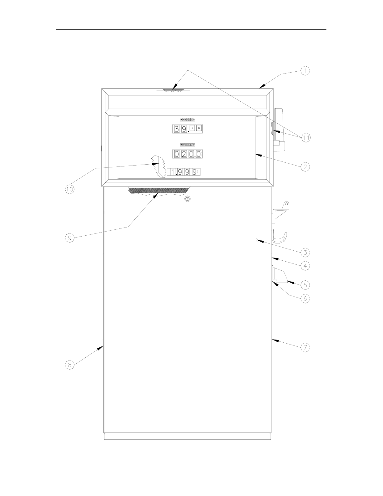
9753E, 9753EHC, 9753EX SINGLE - FRONT VIEW
2 03/07/03
Page 7

Parts List
9753E, 9753EHC, 9753EX SINGLE - FRONT VIEW
Item Part No. Description
1 022453 Top Cover Weld Assy., Painted (See Note)
022452 Top Cover Weld Assy., SS.
2 Dial Enclosure Assy. (See Dial Enclosure breakdown for your model)
3 040798 Panel and Lock Assy., Painted, Single, (See Note)
040797 Panel and Lock Assy., SS, Single
*035018 Lock and Key (Not Shown)
4 041119 Right Side Panel, Painted
041118 Right Side Panel, SS
041144 Right Side Panel, w/Internal Retriever, Painted
041143 Right Side Panel, w/Internal Retriever, SS
5 024895 Elbow, Discharge
6 028960 Grommet, Discharge, 1"
7 049901 Rivet, CBT 5/32
8 041086 Left Side Panel, Painted (See Note)
041085 Left Side Panel, SS
9 026838 Gasket, ¼”T x ½”W x 6’
10 025777 Dial Face, VR10 (Decimal point locations, unless specified otherwise: xxx.x money, xxx.x
volume, x.xxx price)
025888 Dial Face, VR10/4 (Decimal point locations as shown, unless specified otherwise)
11 026839 Gasket, 1/16” x ½” x 12’
NOTE: Specify standard color (black, white, red). If not a standard color, specify serial
number of pump/dispenser.
03/07/03 3
Page 8
Gasboy Series 9700E
9753E, 9753EHC, 9753EX SINGLE - SIDE VIEW
4 03/07/03
Page 9

Parts List
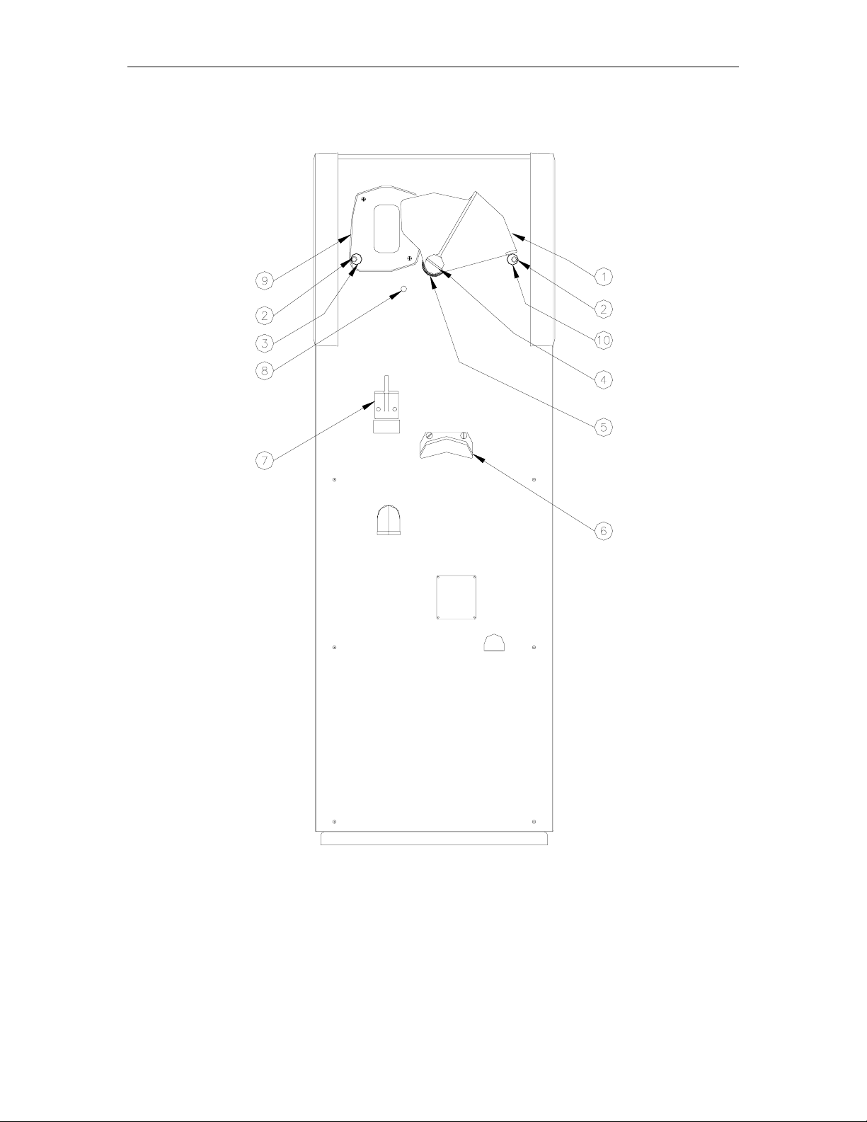
9753E, 9753EHC, 9753EX SINGLE - SIDE VIEW
Item Part No. Description
1 003354 Control Lever, Electric Reset
003353 Control Level, Manual Reset
2 053111 Screw, 5/16-18 x 1, Hex Soc Cap
3 063204 Stop, Eccentric
4 042657 Roll Pin, Electric Reset
043105 Roll Pin, Manual Reset
5 028933 Grommet, Control Lever
6 003740 Hook, Hose
7 003732 Hook, Nozzle
8 047217 Plug Button
9 003333 Boot, Nozzle
10 063204 Stop, Eccentric (Electric Reset)
063023 Stop, Obround (Manual Reset)
03/07/03 5
Page 10
Gasboy Series 9700E
9753E TWIN - FRONT VIEW
6 03/07/03
Page 11

Parts List
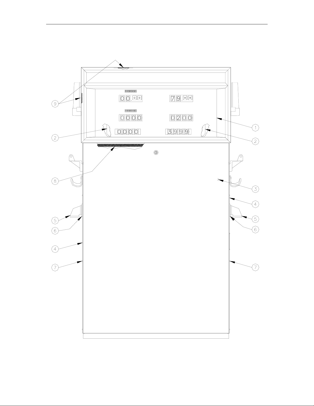
9753E TWIN - FRONT VIEW
Models: 9753ETW1, 9753EXTW1, 9753EXTW2, 9753ETW2, 9753ETW1M
Item Part No. Description
1 Dial Enclosure Assy. (See Dial Enclosure breakdown for your model)
2 025777 Dial Face, VR10 (Decimal point locations, unless specified otherwise: xxx.x money, xxx.x
volume, x.xxx price)
025888 Dial Face, VR10/4 (Decimal point locations as shown, unless specified otherwise)
3 040824 Panel and Lock Assy., Painted, Twin, (See Note)
040823 Panel and Lock Assy., SS, Twin
*035018 Lock and Key (Not Shown)
4 041119 Panel, Side, Painted, ETW1, EXTW1, EXTW2 (See Note)
041118 Panel, Side, SS, ETW1, EXTW1, EXTW2
041144 Right Side Panel w/Internal Retriever, Painted, ETW1, EXTW1,EXTW2 (See Note)
041143 Right Side Panel w/Internal Retriever, SS, ETW1, EXTW1,EXTW2
041116 Panel, Side, Painted, ETW2, ETW1M (See Note)
041115 Panel, Side, SS, ETW2, ETW1M
041142 Right Side Panel w/Internal Retriever, Painted, ETW2, ETW1M
041141 Right Side Panel w/Internal Retriever, SS, ETW2, ETW1M
5 024895 Elbow, Discharge
6 028960 Grommet, Discharge, 1"
7 049901 Rivet, CBT 5/32
8 026838 Gasket, ¼”T x ½”W x 6’
9 026839 Gasket, 1/16” x ½” x 12’
NOTE: Specify standard color (black, white, red). If not a standard color, specify serial
number of pump/dispenser.
03/07/03 7
Page 12
Gasboy Series 9700E
9753E TWIN - SIDE VIEW
8 03/07/03
Page 13

Parts List
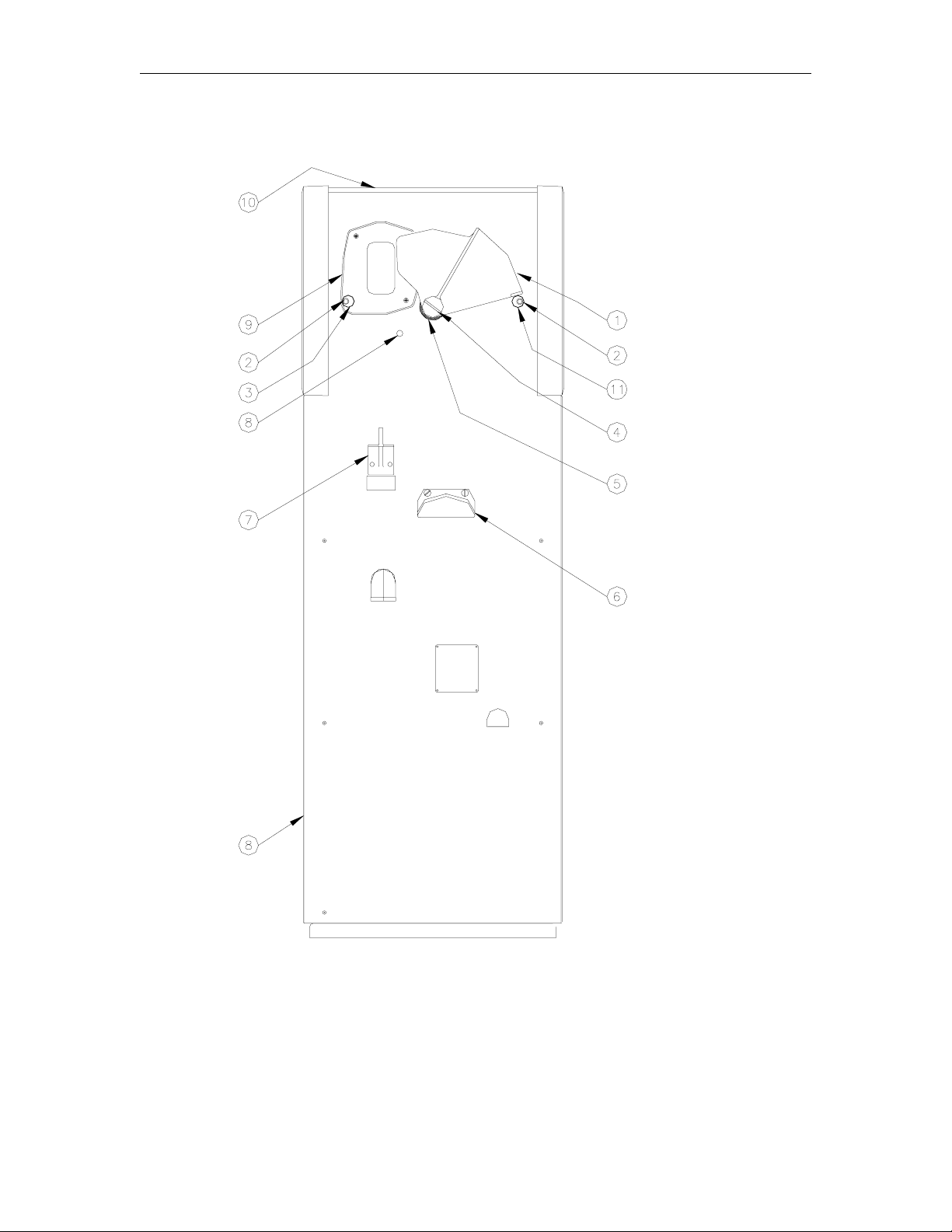
9753E TWIN - SIDE VIEW
Item Part No. Description
1 003354 Control Lever, Electric Reset
003353 Control Lever, Manual Reset
2 053111 Screw, 5/16-18 x 1, Hex Soc Cap
3 063204 Stop, Eccentric
4 042657 Roll Pin, Electric Reset
043105 Roll Pin, Manual Reset
5 028933 Grommet, Control Lever
6 003740 Hook, Hose
7 003732 Hook, Nozzle
8 047217 Plug Button
9 003333 Boot, Nozzle
10 022455 Top Cover Weld Assy., Painted, Twin, (See Note)
022454 Top Cover Weld Assy., SS, Twin
11 063204 Stop, Eccentric (Electric Reset)
063023 Stop, Obround (Manual Reset)
NOTE: Specify standard color (black, white, red). If not a standard color, specify serial
number of pump/dispenser.
03/07/03 9
Page 14
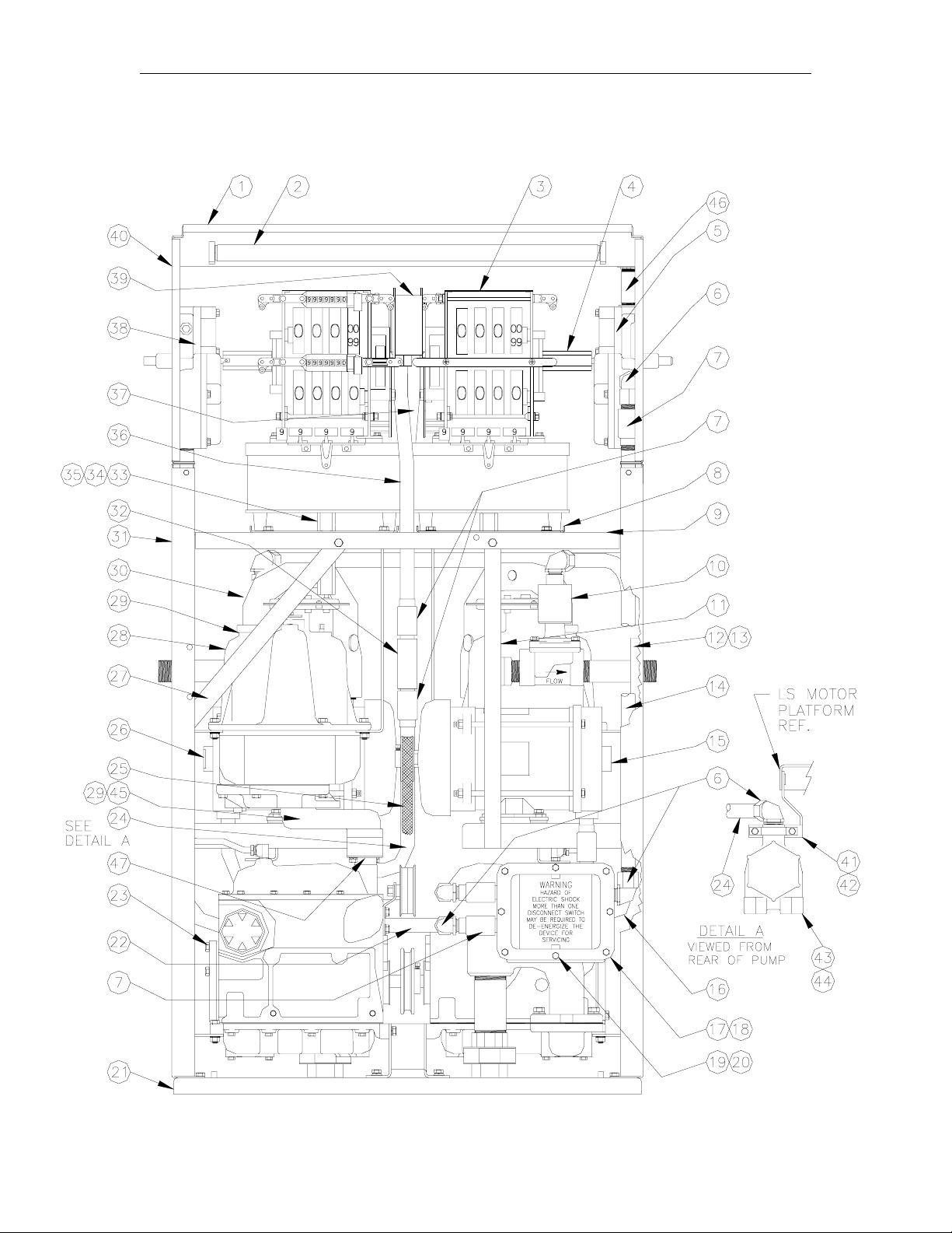
Gasboy Series 9700E
9753E CHASSIS ASSEMBLY
10 03/07/03
Page 15

Parts List
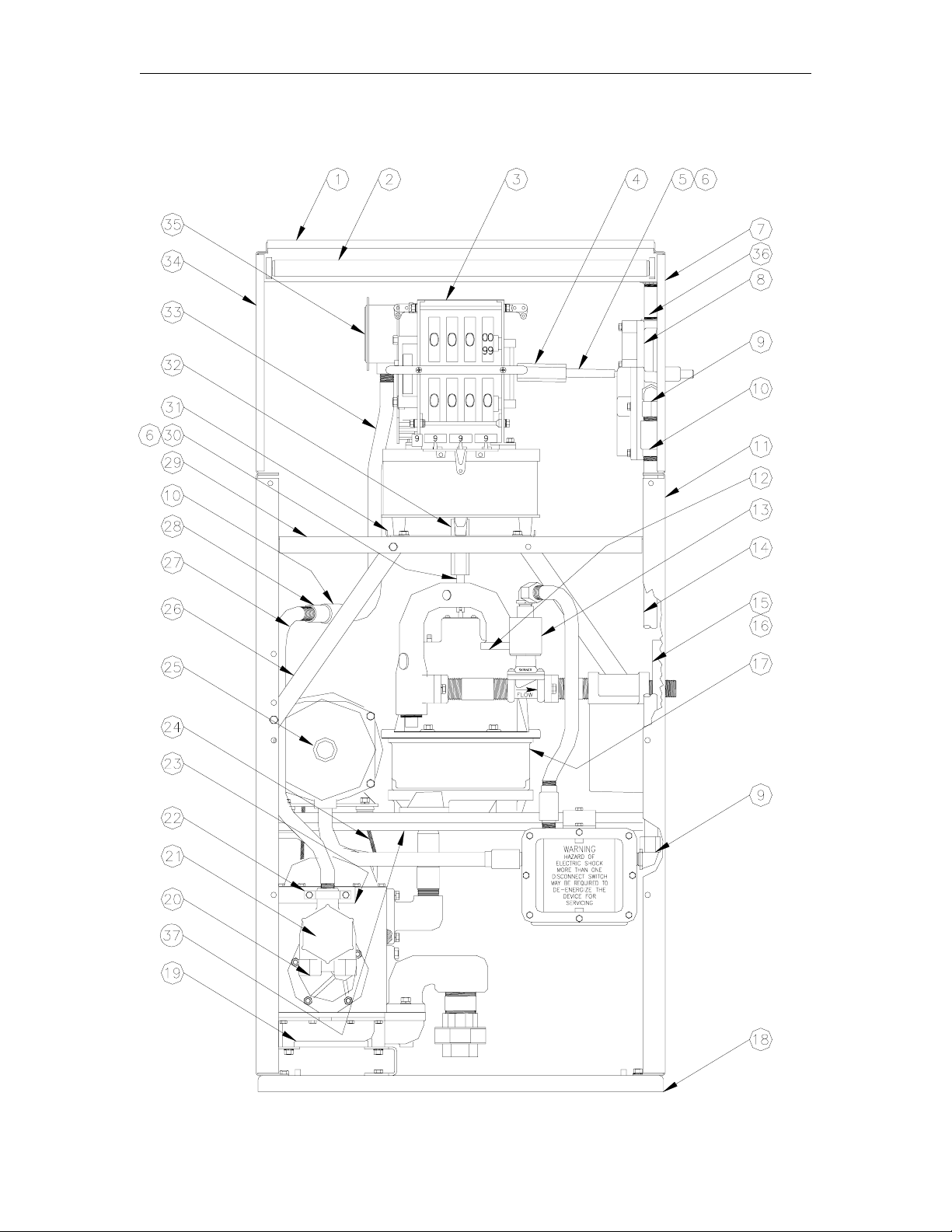
9753E CHASSIS ASSEMBLY
Item Part No. Description
1 026778 Frame, Top Assy.
2 033455 Lamp Assy., 120V, 60 Hz.
033457 Lamp Assy., 120V, 50 Hz.
033461 Lamp Assy., 220V, 60 Hz.
033456 Lamp Assy., 220V, 50 Hz.
3 021009 Computer, VR10, US, Gallons only. Specify serial number of pump for other applications.
020962 Computer, VR10/4 (Typically for Domestic applications)
4 021883 Coupling, Reset/Computer, Electric
022468 Coupling, Reset/Computer, Manual
5 021884 Coupling, Inner Reset/Computer
6 042656 Groove Pin, 1/8 x 1
7 022451 Frame, Top Side
8 Reset Assy, (See table in Electric Reset Breakdown)
9 025045 Elbow, Conduit
10 066400 1/2 UNY Explosion-proof Conduit Union
11 026777 Frame Side Lower
12 027004 Gasket
13 Discharge Assy. (See breakdown for your model)
14 021893 Conduit, Reset/AC Box
15 015478 Discharge Bracket, Inner
16 015479 Discharge Bracket, Outer
17 Meter Assy. (See breakdown Meter Assembly)
18 022321 Base Weld Assy.
19 048726 Pumping Unit Assy.
20 003337 Junction Box, Mach
21 003461 Junction Box Cover, Mach
22 020740 Clamp
23 015605 Pulser Junction Box Bracket
24 012163 Belt, Vee, A35
25 037349 Motor Assy. (See breakdown 9753E Motor)
26 015514 Column Brace
27 023171 Conduit, Pulser, Lower
28 021986 Coupling
29 022448 Column Register Assy.
30 021882 Coupling, Inner, Meter/Computer
31 046701 Plate, Support Reg
32 021883 Coupling
33 023168 Conduit, Pulser, Upper, Qty
023169 Conduit, Pulser, Upper, Money
34 022450 Frame, Top Side
35 046973 Pulser, Qty 10:1
046972 Pulser, Qty, 100:1
032942 Pulser, Money, 100:1
032940 Pulser, Money, 10:1, VR10-4 Only
36 021364 Conduit, 1/2 x 3-1/2
37 Flange Assembly (behind plate; see Flange Assembly breakdown)
03/07/03 11
Page 16
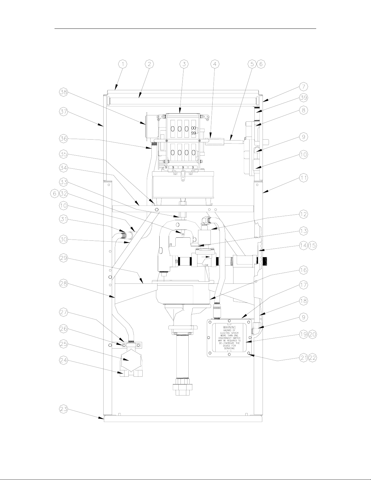
Gasboy Series 9700E
9753EHC CHASSIS ASSEMBLY
12 03/07/03
Page 17

Parts List
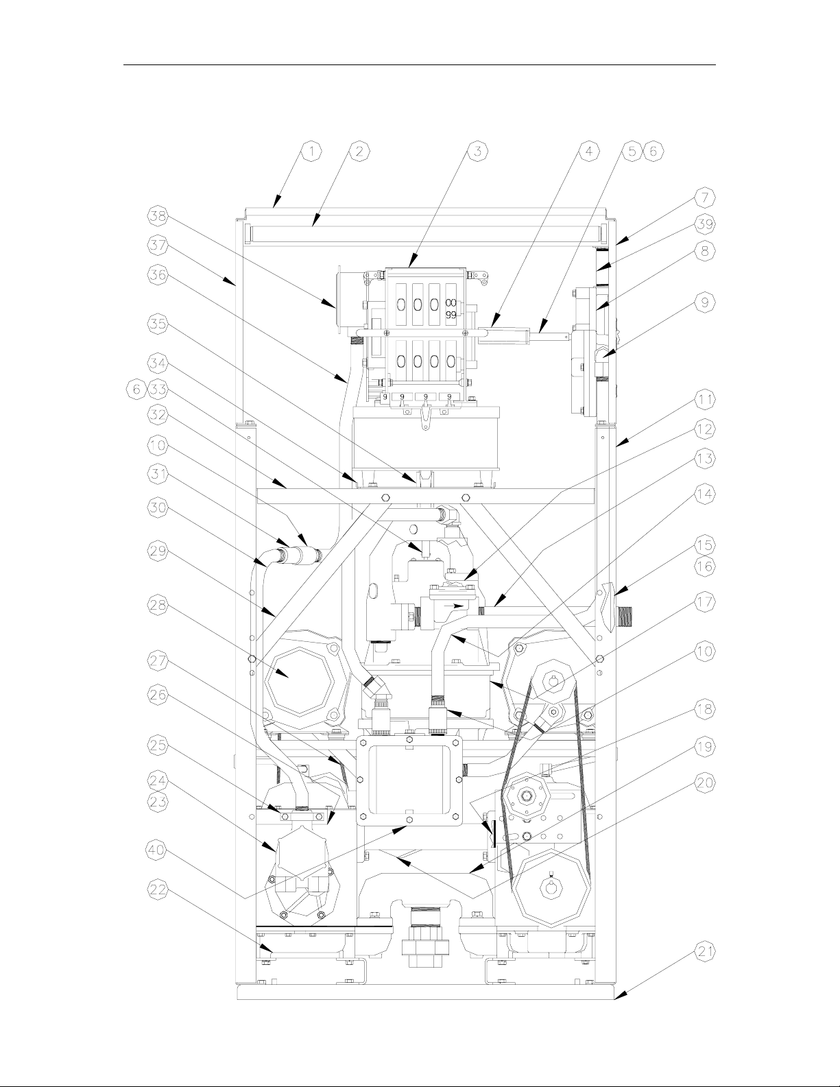
9753EHC CHASSIS ASSEMBLY
Item Part No. Description
1 026778 Frame, Top Assy.
2 033455 Lamp Assy., 120V, 60 Hz.
033457 Lamp Assy., 120V, 50 Hz.
033461 Lamp Assy., 220V, 60 Hz.
033456 Lamp Assy., 220V, 50 Hz.
3 Computer, VR10 (Specify serial number of pump)
020962 Computer, VR10/4 (Typically for Domestic applications)
4 021883 Coupling, Reset/Computer, Electric
022468 Coupling, Reset/Computer, Manual
5 021884 Coupling, Inner Reset/Computer
6 042656 Groove Pin, 1/8 x 1
7 022451 Frame, Top Side
8 Reset Assy, (See table in Electric Reset Breakdown)
9 025045 Elbow, Conduit
10 066400 1/2 UNY Explosion-proof Conduit Union
11 026777 Frame Side Lower
12 027004 Gasket
13 Discharge Assy. (See breakdown for your model)
14 069715 Conduit, Reset/AC Box
15 015478 Discharge Bracket, Inner
16 015479 Discharge Bracket, Outer
17 Meter Assy. (See breakdown Meter Assembly)
18 027003 Gasket
19 035291 Manifold Assembly, (See breakdown)
20 024313 Pump Discharge Assembly, (See breakdown)
21 022321 Base Weld Assy.
22 048726 Pumping Unit Assy.
23 003337 Junction Box, Mach
24 003461 Junction Box Cover, Mach
25 020740 Clamp
26 015605 Pulser Junction Box Bracket
27 012121 Belt, A38
28 037350 Motor Assy., 50 Hz. (See breakdown 9753EHC Motor)
037350 Motor Assy., 50 Hz. (See breakdown 9753EHC Motor)
29 015514 Column Brace
30 023171 Conduit, Pulser, Lower
31 021986 Coupling
32 022448 Column Register Assy.
33 021882 Coupling, Inner, Meter/Computer
34 046701 Plate, Support Reg
35 021883 Coupling
36 023168 Conduit, Pulser, Upper, Qty
023169 Conduit, Pulser, Upper, Money
37 022450 Frame, Top Side
38 046973 Pulser, Qty 10:1
046972 Pulser, Qty, 100:1
032942 Pulser, Money, 100:1
032940 Pulser, Money, 10:1, VR10-4 Only
39 021364 Conduit, 1/2 x 3-1/2
40 Flange Assembly (behind plate; see Flange Assembly breakdown)
03/07/03 13
Page 18
Gasboy Series 9700E
9753ETW1 CHASSIS ASSEMBLY
14 03/07/03
Page 19

Parts List
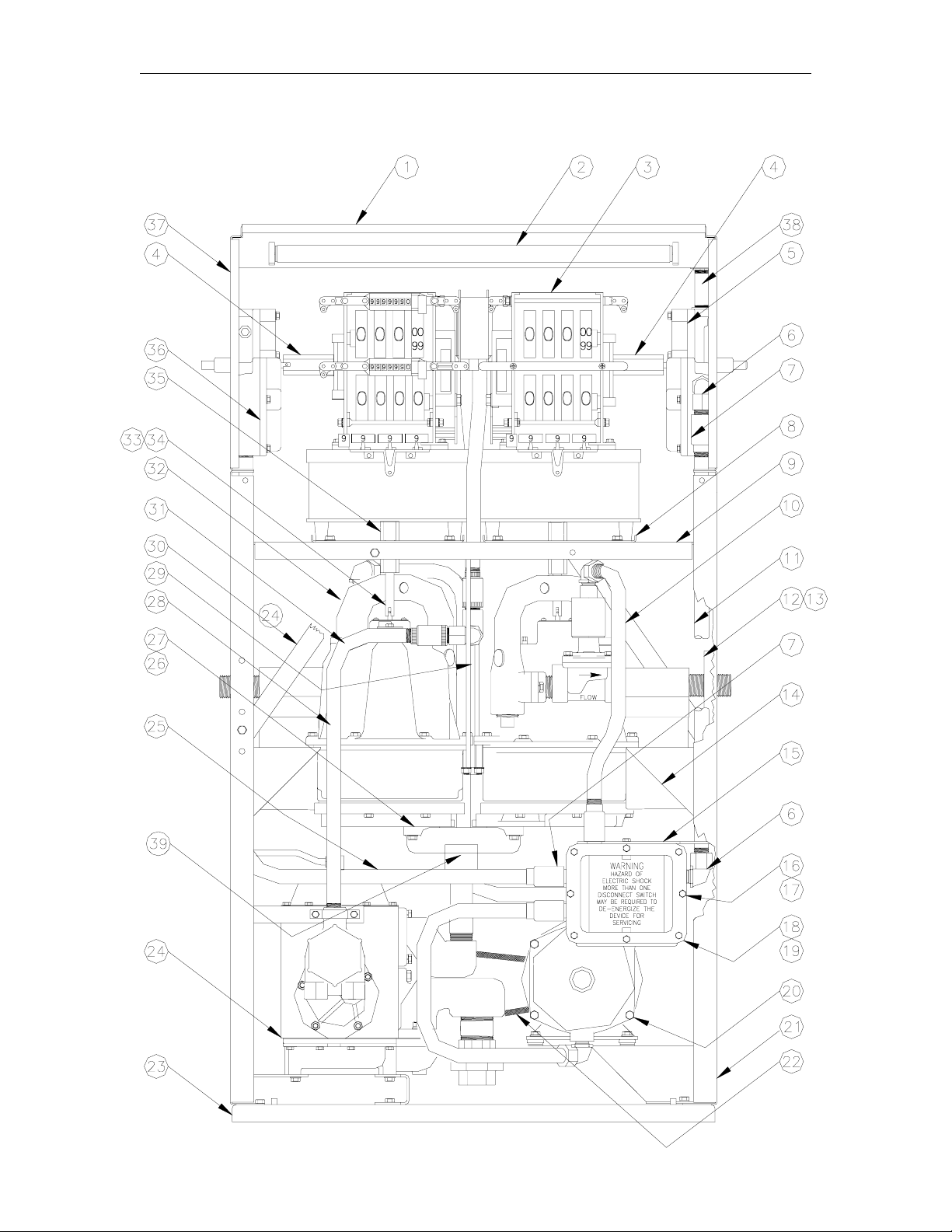
9753ETW1 CHASSIS ASSEMBLY
Item Part No. Description
1 026779 Frame, Top
2 033454 Lamp Assy, Twin, 120V/60 Hz.
033460 Lamp Assy, Twin, 220V/60 Hz.
033459 Lamp Assy, Twin, 120V/50 Hz.
033458 Lamp Assy, Twin, 220V/50 Hz.
3 Computer, VR10 (Specify serial number of pump)
020962 Computer, VR10/4 (Typically for Domestic applications)
4 021933 Coupling, Reset to Computer, Electric
022469 Coupling, Reset to Computer, Manual
5 Reset Assy, (See table in Electric Reset Breakdown)
6 025045 Elbow, Conduit, 1/2 x 90
7 066400 1/2 UNY Explosion-proof Conduit Union
8 046701 Plate, Support Reg
9 022449 Column Register Assy.
10 Discharge Assy., Right (See breakdown for your model)
11 021893 Conduit, Reset/AC Box
12 015479 Discharge Bracket, Outer
13 015478 Discharge Bracket, Inner
14 015523 Bracket, Meter Support
15 014781 Bracket, AC Box, Mounting
16 051808 Screw, 1/4-20 x 7/8 HHC
17 051801 Screw, 1/4-20 x 1 HHC Seal
18 003116 AC Junction Box
19 003117 AC Junction Box Cover
20 037351 Motor Assy. (See breakdown)
21 026777 Frame Side, Lower
22 012174 Belt, A43
23 022314 Base Weld Assy.
24 048739 Pump Assy. (See breakdown)
25 069736 Conduit, Left Side Reset
26 035316 Transfer Body Manifold
27 027004 Gasket
28 Meter Assy. (See breakdown Meter Assembly)
29 015699 Bracket, Meter Mounting, Weld
30 015514 Column Brace
31 M49014 O-Ring, Meth
32 Discharge Assy., Left (See breakdown for your model)
33 021882 Coupling, Inner, Meter/Computer
34 042656 Groove Pin, 1/8 x 1
35 021883 Coupling, Reset/Computer, Electric
36 Reset Assy, (See table in Electric Reset Breakdown)
37 022451 Frame, Top Side
38 021364 Conduit, 1/2 x 3-1/2
39 Flange Assembly (behind plate; see Flange Assembly breakdown)
o
M/F
03/07/03 15
Page 20
Gasboy Series 9700E
9753ETW1M CHASSIS ASSEMBLY
16 03/07/03
Page 21

Parts List
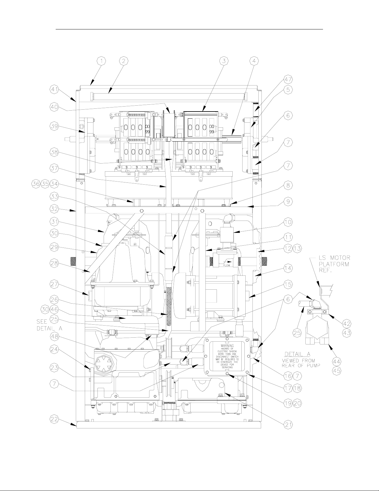
9753ETW1M CHASSIS ASSEMBLY
Item Part No. Description
1 026779 Frame, Top
2 033454 Lamp Assy, Twin, 120V/60 Hz.
033460 Lamp Assy, Twin, 220V/60 Hz.
033459 Lamp Assy, Twin, 120V/50 Hz.
033458 Lamp Assy, Twin, 220V/50 Hz.
3 Computer, VR10 (Specify
serial number of pump)
020962 Computer, VR10/4 (Typically
for Domestic applications)
4 021933 Coupling, Reset to Computer,
Electric
022469 Coupling, Reset to Computer,
Manual
5 Reset Assy, (See table in
Electric Reset Breakdown)
6 025045 Elbow, Conduit, 1/2 x 90o M/F
7 066400 1/2 UNY Explosion-proof
Conduit Union
8 046701 Plate, Support Reg
9 022449 Column Register Assy.
10 Discharge Assy., Right (See
Breakdown)
11 015589 Support Strap
12 015478 Bracket Discharge, Outer
13 015479 Discharge Bracket, Inner
14 021887 Conduit, Right Reset
15 Motor Assy., Right (See
breakdown)
16 021895 Conduit, Valve Lower
17 003116 AC Junction Box
18 003117 AC Junction Box Cover
19 051801 Screw, 1/4-20 x 1 HHC Seal
20 051808 Screw, 1/4-20 x 7/8 HHC
21 035290 Manifold Assy.
22 022314 Base Weld Assy.
23 021886 Conduit, Left, Reset
24 048728 Pumping Unit Assy. (See
breakdown)
25 023178 Conduit, Pulser Lower
Item Part No. Description
26 012176 Belt, A34
27 Motor Assy., Left (See
breakdown)
28 015514 Column Brace
29 Meter Assy. (See breakdown)
30 027004 Gasket
31 Discharge Assy. (See
breakdown)
32 026777 Frame Side Lower
33 064840 Tee
34 021883 Coupling, Reset/Computer,
Electric
35 021882 Coupling, Inner,
Meter/Computer
36 042656 Groove Pin, 1/8 x 1
37 023176 Conduit Pulser, Left (CC & CX)
023172 Conduit, Pulser, Left, Quantity
38 023175 Conduit Pulser, Right (CC &
CX)
023173 Conduit Pulser, Right (CM)
39 Reset Assy, (See table in
Electric Reset Breakdown)
40 046973 Pulser, Qty, 10:1
046972 Pulser, Qty, 100:1
032942 Pulser, Money, 100:1
032940 Pulser, Money, 10:1, VR10-4
Only
41 022451 Frame, Top Side
42 020740 Clamp
43 015713 Bracket, DC Box Mounting
44 003337 Junction Box, Mach
45 003461 Junction Box Cover, Mach
46 035317 Manifold
47 021364 Conduit, 1/2 x 3-1/2
48 Flange Assembly (behind
plate; see Flange Assembly
breakdown)
03/07/03 17
Page 22
Gasboy Series 9700E
9753ETW2 CHASSIS ASSEMBLY
18 03/07/03
Page 23

Parts List
9753ETW2 CHASSIS ASSEMBLY
Item Part No. Description
1 026779 Frame, Top
2 033454 Lamp Assy, Twin, 120V/60 Hz.
033460 Lamp Assy, Twin, 220V/60 Hz.
033459 Lamp Assy, Twin, 120V/50 Hz.
033458 Lamp Assy, Twin, 220V/50 Hz.
3 Computer, VR10 (Specify
serial number of pump)
020962 Computer, VR10/4 (Typically
for Domestic applications)
4 021933 Coupling, Reset to Computer,
Electric
022469 Coupling, Reset to Computer,
Manual
5 Reset Assy, (See table in
Electric Reset Breakdown)
6 025045 Elbow, Conduit, 1/2 x 90o M/F
7 066400 1/2 UNY Explosion-proof
Conduit Union
8 046701 Plate, Support Reg
9 022449 Column Register Assy.
10 Discharge Assy., Right (See
breakdown for your model)
11 015689 Support Strap
12 015479 Discharge Bracket Assy., Inner
13 015478 Bracket Discharge, Outer
14 021887 Conduit, Right Reset
15 Motor Assy., Right (See
breakdown)
16 021895 Conduit, Valve Lower
17 003117 AC Junction Box Cover
18 003116 AC Junction Box
19 051808 Screw, 1/4-20 x 7/8 HHC
20 051801 Screw, 1/4-20 x 1 HHC Seal
21 022314 Base Weld Assy.
22 021886 Conduit, Left Reset
23 Pumping Unit Assy, (See
breakdown)
24 023178 Conduit, Pulser Lower
25 012176 Belt, A34
Item Part No. Description
26 Motor Assy, Left (See
breakdown)
27 015514 Column Brace
28 Meter Assy.
29 027004 Gasket
30 Discharge Assy. (See
breakdown for your model)
31 026777 Frame Side Lower
32 064840 Tee
33 021883 Coupling, Reset/Computer,
Electric
34 042656 Groove Pin, 1/8 x 1
35 021882 Coupling, Inner,
Meter/Computer
36 023176 Conduit Pulser, Left (CC & CX)
023172 Conduit, Pulser, Left, Quantity
37 023175 Conduit Pulser, Right (CC &
CX)
023173 Conduit Pulser, Right (CM)
38 Reset Assy, (See table in
Electric Reset Breakdown)
39 046973 Pulser, Qty, 10:1
046972 Pulser, Qty, 100:1
032942 Pulser, Money, 100:1
032940 Pulser, Money, 10:1, VR10-4
Only
40 022451 Frame, Top Side
41 020740 Clamp
42 015713 Bracket, DC Box Mounting
43 003337 Junction Box, Mach
44 003461 Junction Box Cover, Mach
45 035317 Manifold
46 021364 Conduit, 1/2 x 3-1/2
47 Flange Assembly (behind
plate; see Flange Assembly
breakdown)
03/07/03 19
Page 24
Gasboy Series 9700E
9753EX CHASSIS ASSEMBLY
20 03/07/03
Page 25

Parts List
9753EX CHASSIS ASSEMBLY
Item Part No. Description
1 026778 Frame, Top
2 033455 Lamp Assy., 120V, 60 Hz.
033457 Lamp Assy., 120V, 50 Hz.
033461 Lamp Assy., 220V, 60 Hz.
033456 Lamp Assy., 220V, 50 Hz.
3 Computer, VR10 (Specify serial number of pump)
020962 Computer, VR10/4 (Typically for Domestic applications)
4 021883 Coupling, Reset/Computer, Electric
022468 Coupling, Reset/Computer, Manual
5 021884 Coupling, Inner Reset/Computer
6 042656 Groove Pin, 1/8 x 1
7 022451 Frame, Top Side
8 Reset Assy, (See table in Electric Reset Breakdown)
9 025045 Elbow, Conduit, 1/2 x 90
10 066400 1/2 UNY Explosion-proof Conduit Union
11 026777 Frame Side Lower
12 Discharge Assy., Right (See breakdown for your model)
13 027004 Gasket
14 015478 Discharge Bracket, Outer
15 015479 Discharge Bracket, Inner
16 Meter Assy. (See breakdown Meter Assembly)
17 014781 Bracket, AC Box, Mounting
18 021893 Conduit, Reset/AC Box
19 003116 AC Junction Box
20 003117 AC Junction Box Cover
21 051808 Screw, 1/4-20 x 7/8 HHC
22 051801 Screw, 1/4-20 x 1 HHC Seal
23 022321 Base Weld Assy.
24 003337 Junction Box, Mach
25 003461 Junction Box Cover, Mach
26 020740 Clamp
27 015605 Bracket, Weld Assy.
28 023171 Conduit, Pulser, Lower
29 015529 Bracket, Meter Support
30 015514 Column Brace
31 021986 Coupling
32 021882 Coupling, Inner, Meter/Computer
33 021883 Coupling, Reset/Computer, Electric
34 022448 Column, Register Assy.
35 046701 Plate, Support Reg
36 023168 Conduit, Pulser, Upper, Qty
023169 Conduit, Pulser, Upper, Money
37 022450 Frame, Top Side
38 046973 Pulser, Qty 10:1
046972 Pulser, Qty, 100:1
032942 Pulser, Money, 100:1
032940 Pulser, Money, 10:1, VR10-4 Only
39 021364 Conduit, 1/2 x 3-1/2
o
M/F
2115 21
Page 26

Gasboy Series 9700E
9753EXTW1 CHASSIS ASSEMBLY
22 03/07/03
Page 27

Parts List
9753EXTW1 CHASSIS ASSEMBLY
Item Part No. Description
1 026779 Frame, Top
2 033454 Lamp Assy, Twin, 120V/60 Hz.
033460 Lamp Assy, Twin, 220V/60 Hz.
033459 Lamp Assy, Twin, 120V/50 Hz.
033458 Lamp Assy, Twin, 220V/50 Hz.
3 Computer, VR10 (Specify serial number of pump)
020962 Computer, VR10/4 (Typically for Domestic applications)
4 021933 Coupling, Reset to Computer, Electric
022469 Coupling, Reset to Computer, Manual
5 Reset Assy, (See table in Electric Reset Breakdown)
6 025045 Elbow, Conduit, 1/2 x 90
7 066400 1/2 UNY Explosion-proof Conduit Union
8 046701 Plate, Support Reg
9 022449 Column Register Assy.
10 Discharge Assembly, Right (See breakdown for your model)
11 021893 Conduit, Reset/AC Box
12 015479 Discharge Bracket, Inner
13 015478 Bracket Discharge, Outer
14 015523 Bracket, Meter Support
15 026777 Frame Side Lower
16 014781 Bracket, AC Box, Mounting
17 003117 AC Junction Box Cover
18 003116 AC Junction Box
19 051801 Screw, 1/4-20 x 1 HHC Seal
20 051808 Screw, 1/4-20 x 7/8 HHC
21 022314 Base Weld Assy.
22 035292 Manifold Assy. (See breakdown 9753EXTW1 Manifold Assy.)
23 069736 Conduit, Left Reset
24 015699 Bracket, Meter Mounting, Weld
25 035700 Meter, 2:1 Liter
035517 Meter, 4:1 Gallons
035587 Meter, 4:1 Imperial Gallons
26 015514 Column Brace
27 027004 Gasket
28 Discharge Assembly., Left (See breakdown for your model)
29 021882 Coupling, Inner, Meter/Computer
30 042656 Groove Pin, 1/8 x 1
31 021883 Coupling, Reset/Computer, Electric
32 Reset Assy, (See table in Electric Reset Breakdown)
33 022451 Frame, Top Side
34 021364 Conduit, 1/2 x 3-1/2
o
M/F
2115 23
Page 28

Gasboy Series 9700E
9753EXTW2 CHASSIS ASSEMBLY
24 03/07/03
Page 29

Parts List
9753EXTW2 CHASSIS ASSEMBLY
Item Part No. Description
1 026779 Frame, Top
2 033454 Lamp Assy, Twin, 120V/60 Hz.
033460 Lamp Assy, Twin, 220V/60 Hz.
033459 Lamp Assy, Twin, 120V/50 Hz.
033458 Lamp Assy, Twin, 220V/50 Hz.
3 Computer, VR10 (Specify serial number of pump)
020962 Computer, VR10/4 (Typically for Domestic applications)
4 021933 Coupling, Reset to Computer, Electric
022469 Coupling, Reset to Computer, Manual
5 Reset Assy, (See table in Electric Reset Breakdown)
6 025045 Elbow, Conduit, 1/2 x 90
7 066400 1/2 UNY Explosion-proof Conduit Union
8 046701 Plate, Support Reg
9 022449 Column Register Assy.
10 Discharge Assembly, Right (See breakdown for your model)
11 021893 Conduit, Reset/AC Box
12 015479 Discharge Bracket, Inner
13 015478 Bracket Discharge, Outer
14 015523 Bracket, Meter Support
15 014781 Bracket, AC Box, Mounting
16 003116 AC Junction Box
17 003117 AC Junction Box Cover
18 051808 Screw, 1/4-20 x 7/8 HHC
19 051801 Screw, 1/4-20 x 1 HHC Seal
20 026777 Frame Side Lower
21 022314 Base Weld Assy.
22 069736 Conduit, Left Reset
23 015699 Bracket, Meter Mounting, Weld
24 035700 Meter, 2:1 Liter
035517 Meter, 4:1 Gallons
035587 Meter, 4:1 Imperial Gallons
25 015514 Column Brace
26 027004 Gasket
27 Discharge Assembly, Left (See breakdown for your model)
28 021882 Coupling, Inner, Meter/Computer
29 042656 Groove Pin, 1/8 x 1
30 021883 Coupling, Reset/Computer, Electric
31 Reset Assy, (See table in Electric Reset Breakdown)
32 022451 Frame, Top Side
33 021364 Conduit, 1/2 x 3-1/2
o
M/F
2115 25
Page 30

Gasboy Series 9700E
DISCHARGE ASSEMBLIES MATRIX
Model No valve or
Filter
9753E 097171 097187 097181 097161 097172 097173
9753ETW1 N/A 097185 097179 097174 097176 N/A
9753ETW1M 097155 097154 097166 N/A N/A N/A
9753ETW2 097155 097154 097166 N/A N/A N/A
9753EX N/A 097187 097181 097161 097172 N/A
9753EXTW1 N/A 097185 097179 097174 097176 N/A
9753EXTW2 N/A 097185 097179 097174 097176 N/A
9753EHC 097171 097206 097216 N/A N/A N/A
With Valve
115V
With Valve
230V
With Valve &
Filter 115V
With Valve &
Filter 230V
With Filter
No valve
26 03/07/03
Page 31

Parts List
9753E, 9753EX DISCHARGE ASSEMBLY - 097161, 115V; 097172, 230V
Item Part No. Description
1 003016 Discharge Casting, Mach
2 067034 VL Solenoid 1", Skinner, 2-Stg, Top Cond, 60 Hz.
067036 VL Solenoid 1", Skinner, 2-Stg, Top Cond, 220V, 50 Hz.
3 026071 Meter Flange, 1" NPT w/groove
4 044560 Pipe TBE, 1 x 4
5 038035 Pipe TBE, 1 x 1-1/2 Close Nip
6 047305 Plug Pipe, Square Head, 1"
7 027004 Gasket
8 025045 Elbow, Conduit, 1/2 x 90
9 023161 Conduit, Right Valve
11 003087 Adapter, 1" Cimtek 400 Filter
12 066400 1/2 UNY Explosion-proof Conduit Union
13 026018 Filter, High-Flow (Not Shown)
026019 Filter, Hydrosorb (Not Shown)
o
M/F
2115 27
Page 32

Gasboy Series 9700E
9753E, 9753EHC DISCHARGE ASSEMBLY - 097171
Item Part No. Description
1 003099 Discharge Casting, Mach
2 047305 Plug Pipe, Square Hd, 1"
3 044682 Pipe TBE, 1 x 15-1/2
28 03/07/03
Page 33

Parts List
9753E DISCHARGE ASSEMBLY - 097173
Item Part No. Description
1 003099 Discharge Casting, Mach
2 047305 Plug Pipe, Square Hd, 1"
3 044620 Pipe TBE, 1 x 8
4 003087 Adapter, 1" Cimtek 400 Filter
5 044577 Pipe TBE, 1 x 4-5/8
6 026018 Filter, High-Flow (Not Shown)
026019 Filter, Hydrosorb (Not Shown)
2115 29
Page 34

Gasboy Series 9700E
9753E, 9753EX DISCHARGE ASSEMBLY -
097187, 115V; 097181, 230V
Item Part No. Description
1 003016 Discharge Casting, Mach
2 067034 VL Solenoid 1", Skinner, 2-Stg, Top Cond, 120V
067036 VL Solenoid 1", Skinner, 2-Stg, Top Cond, 220V
3 026071 Meter Flange, 1" NPT w/groove
4 044560 Pipe TBE, 1 x 4
5 044635 Pipe TBE, 1 x 8-1/2
6 047305 Plug Pipe, Square Hd, 1"
7 027004 Gasket
8 025045 Elbow, Conduit, 1/2 x 90
9 023161 Conduit, Right Valve
10 066400 1/2 UNY Explosion-proof Conduit Union
o
, M/F
30 03/07/03
Page 35

Parts List
9753ETW1, 9753EXTW DISCHARGE ASSEMBLY - 097185 115V, 097179
230V
Item Part No. Description
1 003016 Discharge Casting, Mach
2 025045 Elbow, Conduit
3 067034 VL Solenoid 1", Skinner, 2-Stg, Top Cond, 115V
067036 VL Solenoid 1", Skinner, 2-Stg, Top Cond, 230V
4 038035 Pipe TBE, 1 x 1-1/2 Close Nip
5 026071 Meter Flange, 1" NPT w/groove
6 027004 Gasket
7 023161 Conduit, Right Valve
8 044614 Pipe TBE, 1 x 7-1/2
9 066400 1/2" UNY Explosion-Proof Conduit
10 023162 Conduit, Left Side Valve
11 047305 Plug Pipe Sq Hd, 1"
2115 31
Page 36

Gasboy Series 9700E
9753ETW1, 9753EXTW1F DISCHARGE ASSEMBLY - 097174 115V, 097176
230V
Item Part No. Description
1 003016 Discharge Casting, Mach
2 025045 Elbow, Conduit
3 067034 VL Solenoid 1", Skinner, 2-Stg, Top Cond, 115V
067036 VL Solenoid 1", Skinner, 2-Stg, Top Cond, 230V
4 038035 Pipe TBE, 1 x 1-1/2 Close Nip
5 026071 Meter Flange, 1" NPT w/groove
6 027004 Gasket
7 023161 Conduit, Right Valve
8 044525 Pipe TBE, 1 x 3
9 066400 1/2" UNY Explosion-Proof Conduit
10 023162 Conduit, Left Side Valve
11 047305 Plug Pipe Sq Hd 1"
12 003087 Adapter, 1" Cimtek 400 Filter
32 03/07/03
Page 37

Parts List
9753ETW1M, 9753ETW2 DISCHARGE ASSEMBLY - 097155
Item Part No. Description
1 003099 Discharge Casting, Mach
2 047310 1" NPT BIP Sq Socket Pipe Plug
3 044660 Pipe TBE, 1 x 10⁻¹/2
2115 33
Page 38

Gasboy Series 9700E
9753ETW1M, 9753ETW2 DISCHARGE ASSEMBLY - 097154, 115V; 097166,
230V
Item Part No. Description
1 003016 Discharge Casting, Mach
2 067034 VL Solenoid 1", Skinner, 2-Stg, Top
Cond, 120V
067036 VL Solenoid 1", Skinner, 2-Stg, Top
Cond, 220V
3 038035 Pipe TBE, 1 x 1-1/2 Close Nip
4 026071 Meter Flange, 1" NPT w/groove
5 027004 Gasket
6 025045 Elbow, Conduit, 1/2 x 90o, M/F
7 021896 Conduit, Upper Left
8 021894 Conduit, Upper Right
9 047305 Plug Pipe, Square Head, 1"
10 066400 1/2 UNY Explosion-proof Conduit
Union
11 064830 Tee
12 021895 Conduit, Valve Lower
13 044581 Pipe TBE, 1 x 5-1/2
34 03/07/03
Page 39

Parts List
9753EHC PP DISCHARGE ASSEMBLY - 097206 115V, 097216 230V
Item Part No. Description
1 003016 Discharge Casting, Mach
2 069716 Conduit, Solenoid
3 025045 Elbow, Conduit
4 067034 VL Solenoid 1", Skinner, 2-Stg, Top Cond, 115V
067036 VL Solenoid 1", Skinner, 2-Stg, Top Cond, 230V
5 044660 Pipe TBE, 1 x 10⁻¹/2
6 038035 Pipe TBE, 1 x 1-1/2 Close Nip
7 026071 Meter Flange, 1" NPT w/groove
8 066400 1/2 UNY Explosion-proof Conduit Union
9 025015 Elbow, Conduit, 1/2 x 45
10 047305 Plug Pipe, Square Hd, 1"
11 027004 Gasket
o
M/F
2115 35
Page 40

Gasboy Series 9700E
CHECK VALVES
Models: 9753EX, 9753EXTW1, 9753EXTW2
Item Part No. Description
1 035319 Check Valve Assy.
2 027005 Gasket
Model: 9753EHC and 9753ETW1M units (gasoline only)
035239 Check Valve Assembly*
Item Part No. Description
1 058018 Valve Seat
2 058017 Poppet Disc Assy.
3 058016 Spring, Gasoline
058022 Spring, Diesel
4 027001 Pump Inlet Gasket
36 03/07/03
Page 41

Parts List
DIAL ENCLOSURE ASSEMBLY, SINGLE
Item Part No. Description
1 026294 Dial Enclosure Assembly Complete, Single, without totalizer window
026295 Dial Enclosure Assembly Complete, Single, with totalizer window
These assemblies include all of the items listed below. When ordering a complete dial
enclosure assembly, please also specify one of the following silkscreened text variations:
026318 Gallons, standard silkscreen for non-totalizer side
026319 Gallons, standard silkscreen for totalizer side
NOTE: If you have special paint, foreign text, etc. you must include the serial number of your dispenser
2 053737 Screw, 8-32 x 3/8, self-tapping (7 across bottom of sheet metal)
3 Bezel, Plastic (Not available for individual sale, see NOTE 2)
4 011309 Latch Bar, Single
5 028837 Display Glass, w/optional silkscreen
6 039069 Nut, Hex Keps
7 011368 Lock Bar, Single, Retail Plastic Bezel
8 Silkscreened Dial Enclosure (Not available for individual sale, see NOTE 2)
9 028722 Dial Glass (See NOTE 1)
10 C08099 Silicone Sealant (See NOTE 1)
11 033716 Lens (See NOTE 1)
12 053640 Screw, 8-18 x 3/8, self-tapping
13 027019 Gasket, 10 ft. strip
NOTE 1: When replacing individual components, such as the dial glass or lens, you must use
NOTE 2: The part numbers for the plastic bezel and the silkscreened sheet metal are not listed
with your order.
silicone sealant to properly seal the unit from external moisture.
individually, since they must be ordered only as part of the complete dial enclosure
assembly.
03/07/03 37
Page 42

Gasboy Series 9700E
DIAL ENCLOSURE ASSEMBLY, TWIN
Item Part No. Description
1 026296 Dial Enclosure Assembly Complete, Twin (Includes all of the items listed below)
Silkscreen note: This dial enclosure is white with black text and contains the standard Gallons, US $ text,
silkscreen P/N 026320). If your dispenser has special paint, foreign text, etc. you must
2 053737 Screw, 8-32 x 3/8, self-tapping (7 across bottom of sheet metal)
3 Bezel, Plastic (Not available for individual sale, see NOTE 2)
4 011308 Latch Bar, Twin
5 028839 Silkscreened Display Glass (Specify text to be silkscreened, if required)
6 033716 Lens (See NOTE 1)
7 039069 Nut, Hex Keps
8 011369 Lock bar, Twin, Retail Plastic Bezel
9 028722 Dial Glass (See NOTE 1)
10 C08099 Silicone Sealant (See NOTE 1)
11 Silkscreened Dial Enclosure (Not available for individual sale, see NOTE 2)
12 053640 Screw, 8-18 x 3/8, self-tapping
13 027019 Gasket, 10 ft. strip
NOTE 1: When replacing individual components, such as the dial glass or lens, you must use
NOTE 2: The part numbers for the plastic bezel and the silkscreened sheet metal are not listed
include the serial number of your dispenser with your order.
silicone sealant to properly seal the unit from external moisture.
individually, since they must be ordered only as part of the complete dial enclosure
assembly.
38 03/07/03
Page 43

Parts List
FLANGE ASSEMBLY
Item Part No. Description
1 049014 O-Ring
M49014 O-Ring, Methanol/Ethanol
2 026079 Flange
3 051950 5/16-18 x 1-3/4 HHC Screw
4 068005 1/4 Washer
5 068875 Lockwasher, 5/16
6 027797 Gasket
7 021950 Coupling
MOTOR MOUNT
Item Part No. Description
1 051940 5/16-18 x 1-1/2 HHC Screw
2 068080 5/16 Washer
3 067735 Cup Washer
4 068620 Washer
5 038920 5/16-18 ESNA Nut
6 037885 Rubber Mount
SUPPORT ASSEMBLY
Item Part No. Description
1 038680 1/2-13 Jam Nut
2 068065 1/2 Washer
3 015560 Stud
03/07/03 39
Page 44

Gasboy Series 9700E
ELECTRIC RESET BREAKDOWN
40 03/07/03
Page 45

Parts List
ELECTRIC RESET BREAKDOWN
Item Part No. Description
1 048555 Reset Box and Pin Assembly
2 S00650 Spring Washer
3 S00651 Thrust Washer
5 064466 Switch D P S T
6 S00652 Drive
7 S00653 Pinion
8 S00436 Operator Spring
9 S00654 Leaf Actuator
10 S00437 Reset Switch
12 S00655 Shim Washer
13 S00656 Insulator
14 S00657 Plug
15 067109 Brass Washer
16 S00450 Light Switch
17 023628 Warning Decal (Not Shown)
18 S00658 Cam
19 029359 Handle Operator Assembly
20 064875 Terminal Bracket Assembly
21 S00659 Interponent Assembly
22 S00660 Idler Shaft Assembly
23 S00661 Computer Drive Assembly
24 010008 Actuator Assembly
26 057806 Handle Spring
27 S00435 Reset Motor (60 HZ.)
S00675 Reset Motor (50 HZ. & 60 HZ.,
220 Volt)
The following chart shows the part numbers for the various reset assemblies used on all 9753E single and
twin units. Select the one appropriate for use with your unit.
Part Number Voltage/Frequency Options Cover Assy Only
048568 115V/60Hz Unlit Housing 022289
048677 230V/60Hz Unlit Housing 048668
048658 230V/50Hz. Unlit Housing 022364
048656 115V/60Hz. Lighted Housing* 022290
048676 230V/50Hz. Lighted Housing* 048669
048657 230V/50Hz. Lighted Housing* 022402
Manual Reset Assy.
(See Reset, Manual,
Breakdown)
*NOTE: Lighted twin units utilize an unlit reset assembly on the left side.
28 S00662 Switch Bracket
29 S00663 Cover & Bearing Assembly
32 S00664 Shoulder Screw
33 S00696 Dampener Spring (leaf type,
replaces coil type)
34 S00666 Mach Screw, #6-32 x 3/4 Lg.
Rd. Hd.
35 052686 Mach Screw, #6-32 x 7/8 Lg.
Rd. Hd.
36 S00667 Mach Screw, #6-32 x 1-1/8 Lg.
Rd. Hd.
38 S00668 Adjusting Screw
39 S00669 Hex Nut #10-24
40 051808 Hex Hd Cap Screw, 1/4-20 x
7/8 Lg.
41 052345 Hex Hd Cap Screw, 1/4-20 x 1-
3/4 Lg.
43 S00670 Lockwasher, #6
45 S00671 Lockwasher, #1110
46 068891 Lockwasher, #1114
47 068843 Lockwasher, #1206
48 042656 Groov-Pin, 1/8 x 7/8 Lg
49 S00672 Truarc "E" Retaining Ring
51 S00673 Truarc Retaining Ring
54 048612 Truarc Retaining Ring
55 042912 Pin, Collar
57 Pipe Plug, 1/2" (Not Shown,
unlighted units only)
03/07/03 41
Page 46

Gasboy Series 9700E
9753E HAND CRANK BREAKDOWN
42 03/07/03
Page 47

Parts List
9753E HAND CRANK BREAKDOWN
Item Part No. Description
1 047015 Pulley, 5-1/4 x .75 bore
2 012166 Belt, 23" 4L230
3 012168 Belt, 52" 4L520
4 032004 Housing/Bearing Assy.
5 068040 Washer, .5051D x .880DC, .058 Thick
6 055005 Shaft, Drive w/HC
7 032005 Housing/Bearing Assy. (Dbl)
8 049403 Retaining Ring
048612 Retaining Ring, Truarc, 5100-50
9 014834 Bracket, Support
10 043030 Pin, Roll 3/16 x 1
11 055004 Shaft, Drive, w/HC
12 014835 Bracket, Pulley, w/HC
13 017130 Bushing, Hand Crank
14 048709 Pulley, 2" x .5 bore
15 023139 Hand Crank Assy.
03/07/03 43
Page 48

Gasboy Series 9700E
9753EHC, 9753ETW HAND CRANK BREAKDOWN
44 03/07/03
Page 49

Parts List
9753EHC, 9753ETW HAND CRANK BREAKDOWN
Item Part No. Description
1 043030 Pin, Roll 3/16 x 1
2 014814 Bracket, Hand Crank
3 055004 Shaft, Drive, w/HC
4 047015 Pulley, 5-1/4 x .75 bore
5 017130 Bushing, Hand Crank
6 055005 Shaft, Drive w/HC
7 048709 Pulley, 2" x .5 bore
8 012167 Belt, 49" 4L490
9 032005 Housing/Bearing Assy. (Dbl)
10 068040 Washer, .5051D x .880DC, .058 Thick
11 049403 Retaining Ring
048612 Retaining Ring, Truarc, 5100-50
12 030024 Housing, Bearing Assy.
13 012166 Belt, 23" 4L230
14 023139 Hand Crank Assy.
03/07/03 45
Page 50

Gasboy Series 9700E
HIGH HOSE RETRIEVER
Complete High Hose Retriever installation
requires a support post kit and a hose
clamp/spring reel kit.
032675 Support Post Kit (Contains post and
hardware: Items 3-11 below)
Hose Clamp/Spring Reel Kits
032666 Kit, 5/8" Hardwall/Softwall (1" OD)
032659 Kit, 3/4" Hardwall/Softwall (1-1/32" OD)
032663 Kit, 3/4" Dayco Hardwall (1-1/8" OD)
032667 Kit, 1" Softwall (1-1/2" OD)
032668 Kit, 1" Dayco Hardwall (1-7/16 OD)
032669 Kit, 1" Hardwall (1-3/8 OD)
032671 Kit, HHR, Goodyear Prem, Vapor
Recovery, Coaxial
Item Part No. Description
1 030804 Reel Assy, 5/8" & 3/4"
Hardwall/Softwall
030805 Reel Assy, 1" Softwall, 1"
Hardwall; 1-1/4" Softwall; GY
Prem Coax, Vapor Recovery
2 020714 Clamp, 5/8" Hardwall/Softwall
020712 Clamp, 1" Softwall
020718 Clamp, 1" Hardwall (1-7/16
OD)
020719 Clamp, 1" Hardwall (1-3/8 OD)
026732 Clamp, GY Prem Coax, Vapor
Recovery
3 063818 Support Bar Assy.
4 017930 Caplug
5 051956 Bolt, 5/16-18 x 2, SS
6 051957 Bolt, 5/16-18 x 2-1/2, SS
7 068079 Washer, 5/16, SS
8 068874 Lockwasher, 5/16, SS
9 063208 Spacer
10 047219 Plug Button, 7/8
11 013250 Anchor
46 03/07/03
Page 51

Parts List
INTERNAL RETRIEVER
Item Part No. Description
1 048369 Reel and Cable
2 015456 Bracket, Internal Hose Retriever
3 040035 Cable Guide, Internal Retriever
4 020712 Hose Clamp, 1" Softwall
020719 Hose Clamp, 1" Hardwall
020714 Hose Clamp, 5/8 and ¾
03/07/03 47
Page 52

Gasboy Series 9700E
9753E, 9753EHC, 9753ETW LAMP ASSEMBLY
Item Part No. Description
1 033350 Lampholder, snap in
2 015160 Mounting Bracket, Lamp and Ballast, 9753E
015161 Mounting Bracket, Lamp and Ballast, 9753ETW
3 011152 Ballast, 220V/50 Hz.
011153 Ballast, 115V/50 Hz.
011154 Ballast, 220V/60 Hz.
011155 Ballast, 120V/60 Hz.
4 033436 Lamp, Fluorescent, F20T12/CW
48 03/07/03
Page 53

Parts List
9753EHC MANIFOLD
Item Part No. Description
1 048391 Pump Inlet
2 044907 Pipe Tube, 1-1/2 x 2-1/4
3 066385 Union, 1-1/2 #150 Stockham
9753EHC MANIFOLD PUMP DISCHARGE
Item Part No. Description
1 048396 Pump Discharge
2 058019 Cover
3 015695 Coupling Nipple
4 027002 Gasket
03/07/03 49
Page 54

Gasboy Series 9700E
9753ETW1M MANIFOLD ASSEMBLY
Item Part No. Description
1 003108 Manifold, Pump Inlet
2 044912 Pipe TBE, 1-1/2 x 4-1/2
3 066385 Union, 1-1/2 #150 Stockham
9753EXTW1 MANIFOLD ASSEMBLY
Item Part No. Description
1 035318 Manifold
2 044938 Pipe TBE, 1-1/2 x 6
3 066385 Union, 1-1/2 #150 Stockham
50 03/07/03
Page 55

Parts List
9753EXTW1 METER ASSEMBLY
Item Part No. Description
1 035700 Meter, 2:1 Liter
035517 Meter, 4:1 Gallons
035587 Meter, 4:1 Imperial Gallons
2 027038 Gasket
3 035525 Strainer Body Assy. (See Strainer Body Assembly breakdown)
03/07/03 51
Page 56

Gasboy Series 9700E
9753E, 9753EHC, 9753ETW1 METER ASSEMBLY
Item Part No. Description
1 035700 Meter, 2:1 Liter
035517 Meter, 4:1 Gallons
035587 Meter, 4:1 Imperial Gallons
2 027038 Gasket
3 035514 Meter Transfer Body
52 03/07/03
Page 57

Parts List
9753EXTW2 METER ASSEMBLY
Item Part No. Description
1 035700 Meter, 2:1 Liter
035517 Meter, 4:1 Gallons
035587 Meter, 4:1 Imperial Gallons
2 027038 Gasket
3 035525 Strainer Body Assy. (See Strainer Body Assembly breakdown)
4 048138 Valve Housing
5 044394 Pipe TBE, 1-1/2 x 8
6 066385 Union, 1-1/2 #150 Stockham
03/07/03 53
Page 58

Gasboy Series 9700E
9753ETW2, 9753ETW1M METER ASSEMBLY
Item Part No. Description
1 035565 Meter Assy., Gallons
*035517 Meter
*S00713 Gear Train
035586 Meter Assy., Liters
*035576 Meter
*S00713 Gear Train
035587 Meter, Imperial Gallons
S00713 Gear Train, Imperial Gallons
2 027038 Gasket
3 035514 Meter Transfer Body
54 03/07/03
Page 59

Parts List
Page intentionally left blank.
03/07/03 55
Page 60

Gasboy Series 9700E
9700E METER ASSEMBLY BREAKDOWN
56 03/07/03
Page 61

Parts List
9700E METER ASSEMBLY BREAKDOWN
Item Part No. Description
1 S00466 Packing Gland Plate
2 S00467 Seal Pin
3 S00469 Compensator Screw Spring
4 S00473 Drive Shaft
5 069080 Seal & Seal Wire
6 S00475 Special Screw
7 S00476 Drive Shaft Pin
8 S00477 1/2" Ball
9 S00480 Plunger Cup Support
10 S00481 Plunger Disc
11 S00482 Washer
12 S00483 Washer
13 S00484 Upper Bearing Assembly
14 S00485 Bearing Assembly
15 S00487 Compensator Index Disc
16 S00488 Seal Half
17 S00489 Seal Wedge
18 S00490 Washer
19 S00492 Packing Spring
20 S00493 Seal
23 S00494 Bearing Retainer
24 S00495 Seal (black)
25 S00491 Seal Retaining Ring
26 S00478 Compensator Pinion
27 S00512 Screw
28 S00498 Main Pivot Bracket Assembly
w/ Pins
29 S00032 Plunger Cup Kit (Set of 3
Cups)
30 S00501 Valve
31 S00502 Wobble Plate w/ Slack Roller
Post
32 S00503 Connector
33 S00504 Bearing Seat
35 S00505 Slack Roller Assembly
36 S00506 Slack Spring Assembly
37 S00496 Drive Shaft Gear - Gal
S00115 Drive Shaft Gear - Ltr
Item Part No. Description
38 S00499 Counter Drive Gear Complete -
Gal
S00114 Counter Drive Gear Complete -
Ltr
39 S00497 Compensator Shaft
40 S00500 Bracket & Pin Assembly
41 S00468 Index Plate
42 S00479 Pivot & Ball Assembly
43 S00470 Meter Body Gasket
44 S00471 O-Ring (.362 Dia.)
45 S00472 O-Ring (.487 Dia)
46 S00486 Meter Cover w/ Center Gear
Post, Index Plate, Pipe Plug &
Retaining Ring
47 S00509 Mach. Screw, 10-32 x 3/8 Lg.
Rd. Hd.
48 S00507 Mach. Screw, #12-24 x 1/2 Lg.
Rd. Hd.
49 S00508 Mach. Screw, 1/4-20 x 3/4 Lg.
Rd. Hd.
50 S00511 Hex Nut, 1/4-20
51 S00510 Hex Nut, 5/16-18
52 S00520 Lockwasher, 1/4
53 S00513 Lockwasher, #1212
54 S00514 Lockwasher, #1114
55 S00515 Pipe Plug, 1/8 Sq. Hd.
56 S00516 Sems Fastener, #10-32 x 3/8
Lg. Rd. Hd.
57 S00517 Cotter Pin, 1/16 x 1/4 Lg.
58 S00518 Truarc Retaining Ring
59 S00519 Truarc "E" Retaining Ring
60 S00521 Plunger Assy. w/ Bearing
Retainer, Bearing Seat & Sems
Fastener
61 S00522 Body & Seat Assembly w/pins
62 S00523 Meter Drive Shaft Kit
63 S00130 Shaft-Seal Kit
03/07/03 57
Page 62

Gasboy Series 9700E
9753E MOTOR
Item Part No. Description
1 F37335 Motor, 3/4-World
F37436 Motor, Franklin, 3/4 HP DVDF RV 56 Fr Tropically Wound
2 015094 Meter and Motor Bracket Weld Assy.
3 031315 Key
4 047302 Pulley, 5/8 Bore, 2.6 Maurey
5 021892 Conduit, Motor/AC Box, 9753E
6 066400 1/2 UNY Explosion-proof Conduit Union
7 003116 AC Junction Box
8 003117 AC Junction Box Cover
9 015697 Bracket, AC Box Support
10 047247 Plug, 1/2 Cond Slotted Alum.
11 051808 Screw, 1/4-20 x 7/8 HHC
12 051801 Screw, 1/4-20 x 1 HHC Seal
58 03/07/03
Page 63

Parts List
9753EHC MOTOR
Item Part No. Description
1 F37696 Motor, 3/4 HP, 60Hz, 56FR, CW
F37429 Motor, 3/4 HP, 50Hz, 56FR, CW
F37413 Motor, 3/4 HP, 50Hz, 56FR, CW, Tropically Wound
2 015094 Meter/Motor Bracket Weld Assy.
3 069718 Conduit, Motor
4 047014 Pulley, 5/8" bore, 3"
5 015786 Bracket, AC J-Box
6 031315 Key
7 069719 Conduit, Motor, Short
8 003116 AC Junction Box
9 003117 AC Junction Box Cover
10 066400 1/2 UNY Explosion-proof Conduit Union
03/07/03 59
Page 64

Gasboy Series 9700E
9753ETW1 MOTOR
Item Part No. Description
1 023158 Conduit, Motor/AC Box
2 066400 1/2 UNY Explosion-proof Conduit Union
3 F37335 Motor, 3/4-World
4 047005 Pulley, 5/8 Bore, 2.4 Maurey, 2240
5 031315 Key
6 015076 Bracket, Motor Support
7 025045 Elbow, Conduit, 1/2 x 90
o
, M/F
60 03/07/03
Page 65

Parts List
9753ETW2, 9753ETW1M MOTOR - RIGHT SIDE
Item Part No. Description
1 047302 Pulley, 5/8 Bore, 2.6 Maurey
2 031315 Key
3 F37335 Motor, 3/4-World
F37436 Motor, Franklin, 3/4 HP DVDF RV 56 Fr Tropically Wound
4 038050 Pipe TBE, 1/2 x 1-1/8
5 063949 Platform, Motor
6 066400 1/2 UNY Explosion-proof Conduit Union
03/07/03 61
Page 66

Gasboy Series 9700E
9753ETW2, 9753ETW1M MOTOR - LEFT SIDE
Item Part No. Description
1 047302 Pulley, 5/8 Bore, 2.6 Maurey
2 031315 Key
3 F37335 Motor, 3/4-World
F37436 Motor, Franklin, 3/4 HP DVDF RV 56 Fr Tropically Wound
4 063949 Platform, Motor
5 021888 Conduit, Motor/AC Box
6 025045 Elbow, Conduit, 1/2 x 90
7 066400 1/2 UNY Explosion-proof Conduit Union
o
, M/F
62 03/07/03
Page 67

Parts List
Page intentionally left blank.
03/07/03 63
Page 68

Gasboy Series 9700E
9753ETW1/9753EXTW PULSER ASSEMBLY
64 03/07/03
Page 69

Parts List
9753ETW1/9753EXTW PULSER ASSEMBLY
Item Part No. Description
1 056895 Spacer, Top, .835 Nom. Length
2 046970 Plate, Mounting
3 056877 Spacer
4 025015 Elbow, Conduit, 1/2 x 45
5 046973 Pulser, 10:1 & Coupling Assy., CX
046972 Pulser, 100:1 & Coupling Assy., CC
032942 Pulser, Money, 100:1
032940 Pulser, Money, 10:1, VR10-4 only
6 069730 Conduit, Pulser, Upper
023172 Conduit, Pulser, Upper, LS, Money
7 066400 1/2 UNY Explosion-proof Conduit Union
8 023175 Conduit, Pulser, RS, Qty.
023173 Conduit, Pulser, RS, Money
9 025045 Elbow, Conduit 1/2 x 90 M/F
10 069732 Conduit, Pulser, Lower
11 064830 Conduit Tee
12 015618 Bracket Weld Assy.
13 020740 Clamp, Junction Box
14 003337 Junction Box
15 003461 Junction Box Cover
16 027044 Plate and Idler Gear Assy.
17 049406 Ring Ret 5133-25-ZF
18 027041 Gear, Quantity
19 031035 Hub, Quan. Shaft Extension
20 043225 Pin, Spirol 5/64 x 7/16 STD PL
o
M/F
03/07/03 65
Page 70

Gasboy Series 9700E
9753E PUMPING UNIT ASSEMBLY
Item Part No. Description
1 065833 Vent Tube Assy., 9753E
2 048392 Pumping Unit
3 026044 Fitting, 3/8 Ct Elbow, Inv Fl
4 047008 Idler Arm
5 047009 Pulley, Idler
6 015695 Coupling Nipple
7 027003 Gasket
8 048397 Pump Discharge
9 048398 Pump Inlet
10 044907 Pipe, TBE, 1-1/2 x 2-1/4
11 066385 Union, 1-1/2 #150 Stockham
12 027001 Pump Inlet Gasket
13 015531 Bracket, Pump Support
14 047597 Pulley, 3/4 Bore, 3-1/2
15 031315 Key
16 015621 Pump Support Bracket, Weld Assy.
66 03/07/03
Page 71

Parts List
9753EHC PUMPING UNIT ASSEMBLY
Item Part No. Description
1 047009 Pulley, Idler
2 047008 Idler Arm
3 048080 Pumping Unit
4 047597 Pulley, 3/4 Bore, 3-1/2
5 031315 Key
6 015621 Pump Support Bracket, Weld Assy.
7 015531 Bracket, Pump Support
8 026044 Fitting, 3/8 Ct Elbow, Inv Fl
9 065833 Vent Tube Assy., 9753E
03/07/03 67
Page 72

Gasboy Series 9700E
9753ETW1 PUMPING UNIT ASSEMBLY
Item Part No. Description
1 015695 Coupling Nipple
2 047009 Pulley, Idler
3 047029 Idler Arm
4 026044 Fitting, 3/8 Ct Elbow, Inv Fl5
5 065832 Vent Tube Assy., 9753E
6 048392 Pumping Unit
7 031315 Key
8 047597 Pulley, 3/4 Bore, 3-1/2
9 015622 Pump Bracket Assy.
10 015531 Bracket, Pump Support
11 027001 Pump Inlet Gasket
12 066385 Union, 1-1/2 #150 Stockham
13 044907 Pipe, TBE, 1-1/2 x 2-1/4
14 048398 Pump Inlet
15 027003 Gasket
16 048399 Pump Discharge
68 03/07/03
Page 73

Parts List
9753ETW1M PUMPING UNIT ASSEMBLY
Item Part No. Description
1 015696 Coupling Nipple, 3-7/8
2 048949 Pumping Unit
3 026206 Fitting, 3/8 Ct Elbow
4 065844 Vent Tube Assy.
5 015623 Pump Support Bracket Weld Assy.
6 031315 Key
7 047597 Pulley, 3/4 Bore, 3-1/2
8 047009 Pulley, Idler
9 047008 Idler Arm
10 065845 Vent Tube Assembly
03/07/03 69
Page 74

Gasboy Series 9700E
9753ETW2 PUMPING UNIT ASSEMBLY
Item Part No. Description
1 015696 Coupling Nipple, 3-7/8
2 048949 Pumping Unit
3 026044 Fitting, 3/8 Ct Elbow
4 063839 Vent Tube Assy.
5 048400 Pump Inlet
6 027001 Pump Inlet Gasket
7 015623 Pump Support Bracket Weld Assy.
8 044912 Pipe TBE, 1-1/2 x 4-1/2
9 066385 Union, 1-1/2 #150 Stockham
10 031315 Key
11 047597 Pulley, 3/4 Bore, 3-1/2
12 047009 Pulley, Idler
13 047008 Idler Arm
70 03/07/03
Page 75

Parts List
Page intentionally left blank.
03/07/03 71
Page 76

Gasboy Series 9700E
PUMPING UNIT ASSEMBLY BREAKDOWN
72 03/07/03
Page 77

Parts List
PUMPING UNIT ASSEMBLY BREAKDOWN
Item Part No. Description
1 S00117 Gasket
2 S00456 Float Lever Pin
3 S00066 Valve Pin
4 S00067 Guide Plate
5 S00068 Spring Plate
6 S00069 Plunger Head
7 S00072 Plunger Plate
8 S00073 Plunger Follower
9 S00074 Valve Cylinder
10 S00075 Cylinder Head
11 S00076 Clamp Plate
12 S00077 Float Valve Body
13 S00079 By-Pass Valve Spring (44-1/2#
Spring)
14 S00080 Vent Screw
15 S00062 Valve Cylinder Gasket
16 S00081 Vent Screw Guard
17 S00082 Float Valve Needle
18 S00083 Float Valve Gasket
19 S00128 Pump Rotor Shaft Assembly
20 S00119 Bottom Head Gasket
21 S00084 Separator Cover
22 S00120 Cover Gasket
23 S00085 Retainer
24 S00121 Bearing
25 S00086 Regulating Poppet Assy
26 S00124 Oil Well Felt
27 S00061 Float Assembly
29 S00718 Gasket
30 063312 Suction Screen (Gasoline, 100
mesh)
063313 Suction Screen (Diesel, 40
mesh)
31 S00088 Regulating Valve Spring
32 S00089 By-pass Valve Poppet
33 S00056 Packing Gland
34 S00090 Packing Spring
35 S00091 Rotary Pump & Separator
Body w/Gasket, Bearing,
Screws & Spring
36 S00092 Regulating Valve Seat
37 S00093 Valve Seat Guide
38 S00094 By-pass Valve Seat
39 S00717 Check Valve Cap
41 S00447 Poppet Spring
43 S00116 "V" Packing
44 S00095 Plunger Guide
Item Part No. Description
45 S00096 Plunger Disc
46 S00097 Plunger Spacer
47 S00122 Drive Shaft Bearing
48 S00129 Rotary Pump Idler
50 S00098 Poppet Disc. & Relief Valve
Assy
52 063261 Suction Strainer Cap
53 S00126 By-pass Valve Assembly (44-
1/2# spring)
54 S00127 Regulating Valve Assembly
55 026768 Gasket
56 S00451 Mach Screw, 1/4-20 x 7/8 Lg.
Rd. Hd.
57 S00452 Hex Hd. Cap Screw, 1/4-20 x
1/2 Lg.
58 S00453 Hex Hd. Cap Screw, 5/16-18 x
7/8 Lg.
59 S00454 Hex. Hd. Cap Screw, 3/8-16 x
2-3/4 Lg.
60 S00455 Hex. Hd. Cap Screw, 3/8-16 x
1-1/8 Lg.
61 S00458 Lockwasher, 3/8 (TW2 and
TW1M)
62 S00457 Cotter Pin, 1/16 x 1/2 Lg.
63 S00459 Pipe Plug, 1/4 Sq. Hd.
64 S00460 Pipe Plug, 1/4 Countersunk
(TW2 and TW1M)
65 S00461 Hex Nut, 1/4 - 28
67 S00462 Lower Pump Head w/Valve
Seat Guides, Regulating Valve
Seat & By-pass Valve Seat
(9753E, 9753EHC, and ETW1)
S00464 Lower Pump Head w/Valve
Seat Guides, Regulating Valve
Seat and By-Pass Valve Seat
(TW2 and TW1M
68 S00057 Rotary Pump Head Assembly
69 S00465 1" Pipe Plug (TW2 and TW1M)
NOTE: For complete rotary pump and air
separator, order:
048392 for models 9753E & 9753ETW1.
048949 for models 9753ETW2 & 9753ETW1M
048080 for model 9753EHC.
03/07/03 73
Page 78

Gasboy Series 9700E
RESET, MANUAL, 048661
74 03/07/03
Page 79

Parts List
RESET, MANUAL, 048661
Item Part No. Description
1 048555 Reset Box and Pin Assembly
2 013102 Snap Ring
3 013034 Wave Spring Washer
4 048612 Truarc Retaining Ring
5 013071 Operator Spring
6 013050 Valve Flange
7 C01171 Lockwasher, #8
8 013104 Machine Screw, #8-32 x 3/8 Fillister Hd
9 064466 Switch, DPST
10 013059 Switch Cover
11 S00670 Lockwasher #6
12 052686 Machine Screw #6-32 x 7/8 Lg. Rd. Hd
13 067109 Brass washer
14 010008 Actuator Assembly
15 013055 Handle, Operator Assy.
16 057806 Handle Spring
17 013126 Output Shaft Assembly
18 048629 Truarc Retaining Ring
19 S00655 Shim Washer
20 013058 Operator Assembly
21 013026 Washer
22 013057 Pawl Assembly
23 013067 Cover and Bearing Assembly
24 068891 Lockwasher #1114
25 051808 Hex Head Cap Screw, ¼-20 x 7/8 Lg
26 052345 Hex Head Cap Screw, ¼-20 x 1-3/4 Lg
27 013129 Groov-pin, 5/32 x 7/8
28 049426 Truarc Retaining Ring. 7/16
29 S00651 Thrust Washer
30 S00450 Light Switch
31 013022 Switch Bracket
32 053624 Screw 6-32 x 5/16 Rd Hd Phil.
33 013029 Plug Shaft (Unlighted)
03/07/03 75
Page 80

Gasboy Series 9700E
STRAINER BODY ASSEMBLY
Item Part No. Description
1 063261 Strainer Cap
2 063312 Gasoline Strainer
(100 mesh)
063313 Diesel Strainer (40
mesh)
3 S00524 Strainer Body
4 026768 O-Ring
5 027005 Gasket
6 035319 Check Valve Assy.
035525 Kit, includes items 1, 2,
3, 4. Specify strainer
type
76 03/07/03
Page 81

Parts List
9753E SERIES FIELD RETROFIT KITS AND ACCESSORIES
Filter Components
Filter Elements – 9753E High Speed Models (up to 22 GPM)
026018 Standard
026019 Hydrosorb
026284 Methanol
External Filter Elements - Super Speed Models (25-40 GPM)
025900 Standard
025901 Hydrosorb
External Filter Kits
032754 External High Flow Kit, 9753E Models (Includes adapter, super speed element and pipe
fittings. Not for use with methanol).
032755 External High Flow Kit with Hydrosorb element, 9753E Models
Pulser Kits (For Field Retrofit)
Models 9753E, 9753EHC, 9753EX
033056 10:1 ratio
033032 100:1 ratio
Models 9753EXTW1, 9753EXTW2
032720 10:1 ratio
032721 100:1 ratio
Models 9753ETW1, 9753ETW2, 9753ETW1M
032737 10:1 ratio
032725 100:1 ratio
Vapor Recovery Field Kits (Balanced System; twins require two kits)
033020 Vapor Recovery Kit. Converts a standard unit to one ready for vapor recovery. Includes
boot and hook only.
048228 Vapor Recovery Complete. Converts a standard unit to one ready for vapor recovery.
Includes high hose retriever, boot, hook, coaxial hose, breakaway, splitter, and jumper
hose.
Hand Crank Kits (For Field Retrofit)
032048 Single hose outlet models (not for use on pumps with optional solenoid valves)
032047 Twin hose outlet models (not for use on 9753ETW1, pumps with optional solenoid valves,
or twin units with pulsers. One kit provides components needed to operate one side of a
twin unit).
High Hose Retriever Kits
See High Hose retriever breakdown page for kit part numbers.
Lamp Kits (For Field Retrofit; one kit contains components for both sides of unit.)
032122 220V/50Hz., single
032123 220V/60Hz., single
032124 120V/60Hz., single
032125 220V/50Hz., twin
032126 220V/60Hz., twin
032127 120V/60Hz., twin
03/07/03 77
Page 82

Gasboy Series 9700E
GW01 - 6/04/02 Rev. 1
WARRANTY
General Statements:
Gasboy International LLC. warrants all new equipment manufactured by Gasboy against defective m aterial and/or workmanship, f or the warranty
period specified below, when the equipment i s installed in accordanc e with specifications prepared by Gasboy.
This warranty does not cover damage caused by acci dent, abuse, Acts of God, lack of surveillance of automatic recording system s, negligence,
mis-application, faulty installation, i mproper or unauthorized maintenance, i nstallation or use in violat i on of product manuals, i nstructions, or warnings.
Under no circumstanc e shall Gasboy be liable for any indirect, special, or cons equent i al damages, losses , or expenses to include, but not limited
to, loss of product, los s of profits, litigation fees , or the use, or inability to use, our product f or any f or any purpos e whatsoever.
Parts Only - During the warranty period, Gasboy will, at its option, repair or replace defective parts returned transportat i on prepaid to its factory.
On-Site Labor Included - Gasboy will also provide, within the Continental United States and during the warranty period, the services of an
Authorized Service Representati ve (A S R) for on-site repair or replacement of defective parts.
Replacement Parts - A ny system com ponents that are not part of the origi nal system order, incl udi ng Island Card Readers, Pump Cont rol Uni ts, etc.,
are considered replacement part s.
Equipment Term Coverage
Commercial Pumps and Dispensers
Full-Cabinet Consumer Pum ps
Small Transfer Pumps, Meters,
Pressure Regulators
Keytrol One year from date of instal l ation or 18 mos. from date of
Fuel Management Systems :
- CFN/ Profit Point
- Series 1000/Fleetkey
- TopKAT
- Fuel Point Readers
(sold with new systems)
Additional Fuel Point Items:
- Fuel Point Readers sold for
retrofitting existing systems.
- Fuel Point vehicle and dispenser
components.
Encoders, Embos sers, Modems,
CRTs, and Logger Printers
Air Diaphragm Pumps Three years from date of purchas e (for full warranty
Items not m anufactured by Gasboy
(ex. automatic nozzles, hoses, swivels,
etc.)
Replacement Parts One year from date of Gasboy International's invoice to the
To the extent permitted by law, this warranty is made in lieu of all other warranties , expressed or implied, incl udi ng warranties of freedom from pat ent
infringement, or merchant abilit y, or fitness for a particular purpos e, or arising from a course of dealing or usage of t rade. No one is authorized to
vary the terms of the warranty nor may anyone make any warranty of representation, or assume any liability other than that herein stated, in
connection with the sale desc ri bed herei n. The acceptance of any order by Gasboy I nt ernational is expressly made subj ect to the purchaser's
agreement to these condit i ons.
78 03/07/03
One year from date of install ation or 18 mos. from date of
Gasboy International’s invoi ce to the purchaser, whichever
comes first.
One year from date of install ation or 18 mos. from date of
Gasboy International’s invoi ce to the purchaser, whichever
comes first.- Excepting the Model 2020 Hand Pump, which
has a 90-day warranty from date of GASBOY International’s
invoice.
Gasboy International’s invoi ce to the purchaser, whichever
comes first.
One year from date of start-up or 15 mos. from date of
Gasboy International’s invoi ce to the purchaser, whichever
comes first .- The basic warranty only applies to systems
which have been started up by a Gasboy Authorized Service
Representative (ASR).
One year from date of start-up or 15 mos. from date of
Gasboy International’s invoi ce to the purchaser,
whichever comes first.
Purchased with Fuel Management Syst em (Encoders,
Embossers only):
90 days from the date of s t art-up by a Gasboy ASR, or 180
days from date of Gasboy I nternational's invoice, whichever
occurs first.
Purchased with Fuel Management System
(Modems, CRTs, and Logger Printers only):
Matches system warranty.
Purchased Separately:
90 days from date of Gasboy International's
invoice to the purchaser.
description, see Price List).
Not warranted by Gasboy International (consul t original
manufacturer’s warranty).
purchaser.
Parts and Labor.
Parts Only.
Parts and Labor.
Parts and Labor.
Parts Only.
Purchased with System
(Encoders, Embos sers only):
Parts only.
Purchased with System (Modems,
CRTs, Logger Printers only):
Matches system warranty.
Purchased Separately:
Parts Only.
Parts Only.
Not Applicable.
Parts Only.
GASBOY INTERNATIONAL LLC
P.O. Box 309, Lansdale, PA 19446 ● (800) 444-5579 ● FAX: (800) 444-5569 ● www.gasboy.com
 Loading...