

Page 1

9120K and 9820K Series AST Pumps
Service and Parts Manual
MDE-4616B
Page 2

Computer Programs and Documentation
Federal Communications Commission (FCC) Warning
All Gasboy computer programs (including software on diskettes and within memory chips) and documentation are copyrighted by, and shall remain the property of, Gasboy. Such
computer programs and documents may also contain trade secret information. The duplication, disclosure, modification, or unauthorized use of computer programs or
documentation is strictly prohibited, unless otherwise licensed by Gasboy.
This equipment has been tested and found to comply with the limits for a Class A digital device pursuant to Part 15 of the FCC Rules. These limits are designed to provide
reasonable protection against harmful interference when the equipment is operated in a commercial environment. This equipment generates, uses, and can radiate radio frequency
energy, and if not installed and used in accordance with the instruction manual, may cause harmful interference to radio communications. Operation of this equipment in a
residential area is likely to cause harmful interference in which case the user will be required to correct the interference at his own expense. Changes or modifications not expressly
approved by the manufacturer could void the user’s authority to operate this equipment.
Approvals
Gasboy, Greensboro, is an ISO 9001:2000 registered facility.
Underwriters Laboratories (UL):
UL File# Products listed with UL
MH4314
MH6418
MH7404
MH10581 Key con t r o l u n i t , M o d e l G K E - B S e r i e s
All dispensers and self-contained pumping
units
Power operated Transfer Pump Models 25,
25C, 26, 27, 28, 72, 72S, 72SP , 72X, 73 and
1820
Hand operated Transfer Pump Models 1230
Series, 1243 Series, 1520 and 1720 Series
Card reader terminals, Models 1000, 1000P
Site controller, Model 2000S CFN Series
Data entry terminals, Model TPK-900 Series
Fuel Point Reader System
New York City Fire Department (NYFD):
NYFD C of A # Product
4823 9100A, 9140A, 9152A, 9153A,
4997 9822A, 9823A
5046 9100Q, 9140Q, 9152Q, 9153Q,
5087 8753K, 8853K, 9153K, 9853K
5091 8752K, 9152K
5129 9122K, 9123K, 9822K, 9823K
9800A, 9840A, 9850A, 9852A,
9853A, 9140
9800Q, 9840Q, 9852Q, 9853Q
(restricted to diesel and nonretail gasoline sales)
National Conference of Weights and Measures (NCWM) - Certificate of Compliance (CoC):
Gasboy pumps and dispensers are evaluated by NCWM under the National Type Evaluation Program (NTEP). NCWM has issued the following CoC:
CoC# Product Model # CoC# Product Model # CoC# Product Model #
95-179 Dispenser
95-136 Dispenser 9800 Series 91-057 Controller
9100 Retail Series, 8700
Series, 9700 Series
91-019 Dispenser
9100 Commercial
Series
1000 Series FMS,
2000S-CFN Series
California Air Resources Board (CARB):
Executive Order # Product
G-70-52-AM Balance Vapor Recovery
G-70-150-AE VaporVac
05-002 Atlas
8700K, 8800K,
9100K, 9200K, 9800K
Patents
Gasboy products are manufactured or sold under one or more of the following US patents:
Dispensers
5,257,720
Point of Sale/Back Office Equipment
D335,673
Trademarks
Non-registered trademarks
Atlas™
Consola™
Infinity™
Registered trademarks
ASTRA
Fuel Point
Gasboy
Keytrol
Slimline
Additional US and foreign patents pending.
®
®
®
®
®
Additional US and foreign trademarks pending.
Other brand or product names shown may be
trademarks or registered trademarks of their
respective holders.
This document is subject to change without notice. · For information regarding Gasboy Literature, call (336) 547-5661
E-mail: literature@gasboy.com · Internet: http://www.gasboy.com
© 2008 GASBOY · All Rights Reserved
Page 3

Table of Contents
1 – Introduction 1
Purpose. . . . . . . . . . . . . . . . . . . . . . . . . . . . . . . . . . . . . . . . . . . . . . . . . . . . . . . . . . . . . . . . . . . . . . . . . .1
General Description. . . . . . . . . . . . . . . . . . . . . . . . . . . . . . . . . . . . . . . . . . . . . . . . . . . . . . . . . . . . . . . . .1
Model 9120K . . . . . . . . . . . . . . . . . . . . . . . . . . . . . . . . . . . . . . . . . . . . . . .1
Model 9820K . . . . . . . . . . . . . . . . . . . . . . . . . . . . . . . . . . . . . . . . . . . . . . .2
Abbreviations and Acronyms. . . . . . . . . . . . . . . . . . . . . . . . . . . . . . . . . . . . . . . . . . . . . . . . . . . . . . . . . .3
2 – Important Safety Information 5
3 – Preventive Maintenance 9
General . . . . . . . . . . . . . . . . . . . . . . . . . . . . . . . . . . . . . . . . . . . . . . . . . . . . . . . . . . . . . . . . . . . . . . . . . .9
Hints for Better Pump Performance. . . . . . . . . . . . . . . . . . . . . . . . . . . . . . . . . . . . . . . . . . . . . . . . . . . . .9
Demand Competent Service . . . . . . . . . . . . . . . . . . . . . . . . . . . . . . . . . . .9
Use Gasboy Authorized Parts . . . . . . . . . . . . . . . . . . . . . . . . . . . . . . . . . .9
Operate with Reasonable Care . . . . . . . . . . . . . . . . . . . . . . . . . . . . . . . .10
Preventive Maintenance . . . . . . . . . . . . . . . . . . . . . . . . . . . . . . . . . . . . . . . . . . . . . . . . . . . . . . . . . . . .10
Keep Water Out . . . . . . . . . . . . . . . . . . . . . . . . . . . . . . . . . . . . . . . . . . . .10
Clean the Dial Face . . . . . . . . . . . . . . . . . . . . . . . . . . . . . . . . . . . . . . . . .10
Clean the Strainer . . . . . . . . . . . . . . . . . . . . . . . . . . . . . . . . . . . . . . . . . .10
Change the Filter . . . . . . . . . . . . . . . . . . . . . . . . . . . . . . . . . . . . . . . . . . .11
Power Reset External Adjustment . . . . . . . . . . . . . . . . . . . . . . . . . . . . . .11
Adjust the Belts . . . . . . . . . . . . . . . . . . . . . . . . . . . . . . . . . . . . . . . . . . . .12
Preserve the Finish of Your Pumps . . . . . . . . . . . . . . . . . . . . . . . . . . . . .12
4 – Parts 13
Base and Motor Shaft . . . . . . . . . . . . . . . . . . . . . . . . . . . . . . . . . . . . . . . . . . . . . . . . . . . . . . . . . . . . . .13
Pump Assembly. . . . . . . . . . . . . . . . . . . . . . . . . . . . . . . . . . . . . . . . . . . . . . . . . . . . . . . . . . . . . . . . . . .15
Meter Shelf, J-Box, and 9123 Register, Reset and Pulser . . . . . . . . . . . . . . . . . . . . . . . . . . . . . . . . . .17
Reset/Register Module. . . . . . . . . . . . . . . . . . . . . . . . . . . . . . . . . . . . . . .19
Pulser Module . . . . . . . . . . . . . . . . . . . . . . . . . . . . . . . . . . . . . . . . . . . . .20
Junction Box Assembly . . . . . . . . . . . . . . . . . . . . . . . . . . . . . . . . . . . . . .22
Meter Assembly . . . . . . . . . . . . . . . . . . . . . . . . . . . . . . . . . . . . . . . . . . . .24
9823 Pulser, Totalizer and Gear Train . . . . . . . . . . . . . . . . . . . . . . . . . . . . . . . . . . . . . . . . . . . . . . . . .25
Panels, Remote Register, Mounting Kits. . . . . . . . . . . . . . . . . . . . . . . . . . . . . . . . . . . . . . . . . . . . . . . .27
9123K. . . . . . . . . . . . . . . . . . . . . . . . . . . . . . . . . . . . . . . . . . . . . . . . . . . .27
9823K. . . . . . . . . . . . . . . . . . . . . . . . . . . . . . . . . . . . . . . . . . . . . . . . . . . .29
Remote Register - Front View . . . . . . . . . . . . . . . . . . . . . . . . . . . . . . . . .30
Remote Register - Side View. . . . . . . . . . . . . . . . . . . . . . . . . . . . . . . . . .31
Remote Register Chassis Assembly - Top View . . . . . . . . . . . . . . . . . . .32
Remote Register Chassis Assembly - Front View . . . . . . . . . . . . . . . . . .33
Remote Register Mounting Option. . . . . . . . . . . . . . . . . . . . . . . . . . . . . .34
Series Kits and Accessories . . . . . . . . . . . . . . . . . . . . . . . . . . . . . . . . . . . . . . . . . . . . . . . . . . . . . . . . .35
MDE-4616B 9120K and 9820K Series AST Pumps Service and Parts Manual · September 2008 Page i
Page 4

This page is intentionally left blank.
Page ii MDE-4616B 9120K and 9820K Series AST Pumps Service and Parts Manual · September 2008
Page 5

Purpose Introduction
1 – Introduction
Purpose
This manual is provided to assist the Gasboy Authorized Service Contractor (ASC) in
servicing the following units used with Aboveground Storage Tanks (ASTs):
• 9120K compact mechanical commercial pump
• 9820K electronic commercial pump
This manual also provides the parts list for the 9X20K units.
Note: Whenever information in this document applies to all the units listed above, the 9X20K
model reference is used.
General Description
Model 9120K
The Gasboy Series 9120K pump units are UL®-listed.
Note: NFPA regulations do not allow tank-mounted pumps to be used for the resale of fuel.
Model 9120K offers four-wheel mechanical-interlock registers. Mechanical pump registers
show the total volume for a delivery up to 999.9 gallons.
Standard features and specifications of the 9120K Series pumps are as follows:
• Discharge elbows
• A 12-foot length of hose
• A working voltage of 115/230VAC, 50/60 Hz
• Mechanical Volume Totalizer
• A switch detect and optional pulser outputs which allow monitoring of the register's
operation when it is connected to an automated fuel management system.
• Four-piston, positive-displacement meter
• Belt-driven, positive-displacement rotary-vane pump with an 80 mesh (300 micron)
strainer and integral air-separation
• Cabinet height of 25.4 inches. The other dimensions may be found on the bas e layout.
• The standard cabinet finish has the top, sides, and back painted black while the front panel
is painted white.
• Filters
MDE-4616B 9120K and 9820K Series AST Pumps Service and Parts Manual · September 2008 Page 1
Page 6

Introduction General Description
The available options and accessories for the Gasboy Series 9120K pumps are as follows:
• Interchangeable Automatic Nozzles
•Pulsers
• Special Lengths of Hose
• Vapor Recovery System
• 380 VAC 3-Phase Motor
Model 9820K
The Gasboy Series 9820K Aboveground Storage Tank Remote Access (ASTRA) pump units
are UL-listed.
Note: NFPA regulations do not allow tank-mounted pumps to be used for the resale of fuel.
The 9820K Series consists of two metal cabinet assemblies.
• One assembly is mounted on top of the tank and contains the pumping unit, meter,
electronic pulser, and all hydraulics. The hose and nozzle are connected to this assembly.
• The second assembly is mounted at a height to permit easy access by a user. It contains the
electronic register, controls, display and nozzle boot.
The Standard features and specifications of the 9820K Series pumps are as follows:
• One-inch high, 6-digit, backlighted Liquid Crystal Display (LCD)
• 1000:1 dual-phase, error-checking pulser (gallons); 250:1 dual-phase, error-checking
pulser (liters)
• AC authorization line for control of the unit
• Reset complete (Switch Detect) output that allows monitoring of the unit's operation when
it is connected to an automated fueling system
• Resettable electronic totalizer
• Discharge elbow
• Both models use a quiet and efficient pump which features an air eliminator, built into the
pump casting. The pump meter is a three piston, positive displacement meter which is
tested and calibrated for accuracy at any speed or pressure up to the maximum working
pressure of 50 psi.
• The standard pumping cabinet finish is white. The electronic register cabinet is black with
a blue graphics panel.
• Dual Stage Solenoid Valve
• Filter
Available options and accessories for the Gasboy 9820K Series pumps are as follows:
• Pulser output drive line (open collector), capable of driving 1, 10, 100, 250 and 500 pulses
per unit (gallons) or 1, 10, & 100 pulses per unit (liters)
• RS-485 communication for direct connect to Gasboy CFN or TopKATΤΜ equipment
• Battery backup for display of last transaction and capture of stored pulse count in the event
of a power failure.
• Mechanical totalizer
• A working voltage of 115 VAC (115/230 for motor) 60 Hz for domestic use, 230 VAC 50
Hz/60 Hz for international use.
• Other options include listed automatic nozzles, special lengths of listed hose assembly,
listed dual swivels, UL-recognized filters, Vapor Recovery, and Vapor Recovery Ready.
Page 2 MDE-4616B 9120K and 9820K Series AST Pumps Service and Parts Manual · September 2008
Page 7

Abbreviations and Acronym s Introduction
Abbreviations and Acronyms
Term Description
AC (or ac) Alternating Current
ASC Authorized Service Contractor
AST Aboveground Storage Tank
ASTRA Aboveground Storage Tank Random Access
CFR Code of Federal Regulations
CPR Cardiopulmonary Resuscitation
CPU Central Processing Unit
DC (or dc) Direct Current
LCD Liquid Crystal Display
NEC National Electrical Code
NFPA National Fire Protection Association
OSHA Occupational Safety and Health Association
PCB Printed Circuit Boards (preferred term: board)
STP Submerged Turbine Pump
UL Underwriters Laboratory
MDE-4616B 9120K and 9820K Series AST Pumps Service and Parts Manual · September 2008 Page 3
Page 8

Introduction Abbreviations and Acronyms
This page is intentionally left blank.
Page 4 MDE-4616B 9120K and 9820K Series AST Pumps Service and Parts Manual · September 2008
Page 9
2 – Important Safety Information
This section introduces the hazards and safety precautions
associated with installing, inspecting, maintaining or servicing
this product. Before performing any task on this product, read
this safety information and the applicable sections in this
manual, where additional hazards and safety precautions for
your task will be found. Fire, explosion, electrical shock or
pressure release could occur and cause death or serious
injury, if these safe service procedures are not followed.
Preliminary Precautions
You are working in a potentially dangerous environment of
flammable fuels, vapors, and high voltage or pressures. Only
trained or authorized individuals knowledgeable in the related
procedures should install, inspect, maintain or service this
equipment.
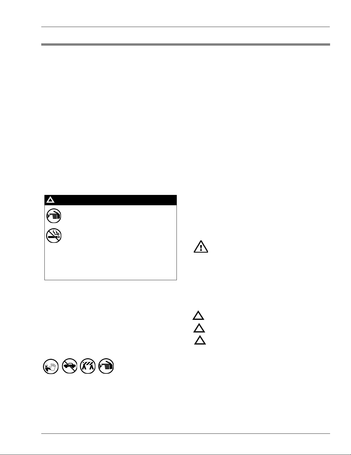
Emergency Total Electrical Shut-Off
The first and most important information you must know is
how to stop all fuel flow to the pump/dispenser and island.
Locate the switch or circuit breakers that shut off all power to
all fueling equipment, dispensing devices, and Submerged
Turbine Pumps (STPs).
!
WARNING
!
The EMERGENCY STOP, ALL STOP, and
PUMP STOP buttons at the cashier’s station
WILL NOT shut off electrical po wer to the p ump/
dispenser. This means that even if you activate
these stops, fuel may continue to flow
uncontrolled.
Read the Manual
Read, understand and follow this manual and any other
labels or related materials supplied with this equipment. If you
do not understand a procedure, call a Gasboy Authorized
Service Contractor or call the Gasboy Service Center at 1800-444-5529. It is imperative to your safety and the safety of
others to understand the procedures before beginning work.
Follow the Regulations
Applicable information is available in National Fire Protection
Association (NFPA) 30A; Code for Motor Fuel Dispensing
Facilities and Repair Garages, NFPA 70; National Electrical
Code (NEC), Occupational Safety and Hazard Association
(OSHA) regulations and federal, state, and local codes. All
these regulations must be followed. Failure to install, inspect,
maintain or service this equipment in accordance with these
codes, regulations and standards may lead to legal citations
with penalties or affect the safe use and operation of the
equipment.
Replacement Parts
Use only genuine Gasboy replacement parts and retrofit kits
on your pump/dispenser. Using parts other than genuine
Gasboy replacement parts could create a safety hazard and
violate local regulations.
Safety Symbols and Warning Words
This section provides important information about warning
symbols and boxes.
Alert Symbol
You must use the TOTAL ELECTRICAL SHUTOFF in the case of an emergency and not the
console’s ALL STOP and PUMP STOP or
similar keys.
Total Electrical Shut-Off Before Access
Any procedure that requires access to electrical components
or the electronics of the dispenser requires total electrical
shut off of that unit. Understand the function and location of
this switch or circuit breaker before inspecting, installing,
maintaining, or servicing Gasboy equipment.
Evacuating, Barricading and Shutting Off
Any procedure that requires access to the pump/dispenser or
STPs requires the following actions:
• An evacuation of all unauthorized persons and vehicles
from the work area
• Use of safety tape, cones or barricades at the affected
unit (s)
• A total electrical shut-off of the affected unit (s)
This safety alert symbol is used in this manual and
on warning labels to alert you to a precaution which must be
followed to prevent potential personal safety hazards. Obey
safety directives that follow this symbol to avoid possible
injury or death.
Signal Words
These signal words used in this manual and on warning
labels tell you the seriousness of particular safety hazards.
The precautions below must be followed to prevent death,
injury or damage to the equipment:
DANGER: Alerts you to a hazard or unsafe practice
!
which will result in death or serious injury.
WARNING: Alerts you to a hazard or unsafe practice
!
that could result in death or serious injury.
CAUTION with Alert symbol: Designates a hazard or
!
unsafe practice which may result in minor injury.
CAUTION without Alert symbol: Designates a hazard
or unsafe practice which may result in property or
equipment damage
Working With Fuels and Electrical Energy
Prevent Explosions and Fires
Fuels and their vapors will explode or burn, if ignited. Spilled
or leaking fuels cause vapors. Even filling customer tanks will
cause potentially dangerous vapors in the vicinity of the
dispenser or island.
MDE-4616B 9120K and 9820K Series AST Pumps Service and Parts Manual · September 2008 Page 5
Page 10
No Open Fire
In an Emergency
Open flames from matches, lighters, welding torches
or other sources can ignite fuels and their vapors.
No Sparks - No Smoking
Sparks from starting vehicles, starting or using power tools,
burning cigarettes, cigars or pipes can also ignite fuels and
their vapors. Static electricity, including an electrostatic
charge on your body, can cause a spark sufficient to ignite
fuel vapors. Every time you get out of a vehicle, touch the
metal of your vehicle, to discharge any ele c tro static charge
before you approach the dispenser island.
Working Alone
It is highly recommended that someone who is capable of
rendering first aid be present during servicing. Familiarize
yourself with Cardiopulmonary Resuscitation (CPR) methods,
if you work with or around high voltages. This information is
available from the American Red Cross. Always advise the
station personnel about where you will be working, and
caution them not to activate power while you are working on
the equipment. Use the OSHA Lockout/ Tagout procedures. If
you are not familiar with this requirement, refer to this
information in the service manual and OSHA documentation.
Working With Electricity Safely
Ensure that you use safe and established practices in working
with electrical devices. Poorly wired devices may cause a fire,
explosion or electrical shock. Ensure that grounding
connections are properly made. Take care that sealing
devices and compounds are in place. Ensure that you do not
pinch wires when replacing covers. Follow OSHA Lockout/
Tagout requirements. Station employees and service
contractors need to understand and comply with this program
completely to ensure safety while the equipment is down.
Inform Emergency Personnel
Compile the following information and inform emergency
personnel:
• Location of accident (for example, address, front/back of
building, and so on)
• Nature of accident (for example, possible heart attack, run
over by car, burns, and so on)
• Age of victim (for example, baby, teenager, middle-age,
elderly)
• Whether or not victim has received first aid (for example,
stopped bleeding by pressure, and so on)
• Whether or not a victim has vomited (for example, if
swallowed or inhaled something, and so on)
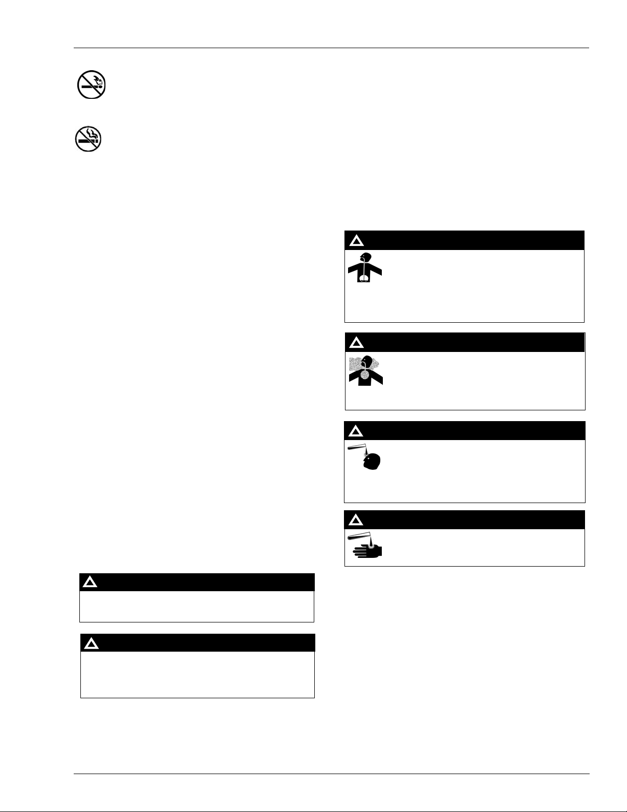
WARNING
!
Gasoline ingested may cause unconsciousness
and burns to internal organs.
Do not induce vomiting.
Keep airway open.
Oxygen may be needed at scene.
Seek medical advice immediately.
WARNING
!
Gasoline inhaled may cause unconsciousness
and burns to lips, mouth and lungs.
Keep airway open.
Seek medical advice immediately.
WARNING
!
Gasoline spilled in eyes may cause burns to eye
tissue.
Irrigate eyes with water for approximately 15
minutes.
Seek medical advice immediately.
Hazardous Materials
WARNING
Some materials present inside electronic enclosures may
present a health hazard if not handled correctly. Ensure that
you clean hands after handling equipment. Do not place any
equipment in the mouth.
!
WARNING
The pump/dispenser contains a chemical known to the
State of California to cause cancer.
!
Gasoline spilled on skin may cause burns.
Wash area thoroughly with clear water.
Seek medical advice immediately.
IMPORTANT: Oxygen may be needed at scene if gasoline
has been ingested or inhaled. Seek medical advice
immediately.
Lockout/Tagout
WARNING
!
Lockout/Tagout covers servicing and maintenance of
machines and equipment in which the unexpected
The pump/dispenser contains a chemical known to the
State of California to cause birth defects or other
reproductive harm.
energization or start-up of the machine(s) or equipment or
release of stored energy could cause injury to employees or
personnel. Lockout/Tagout applies to all mechanical,
hydraulic, chemical or other energy, but does not cover
electrical hazards. Subpart S of 29 CFR Part 1910 - Electrical
Hazards, 29 CFR Part 1910.333 contains specific Lockout/
Tagout provision for electrical hazards.
Page 6 MDE-4616B 9120K and 9820K Series AST Pumps Service and Parts Manual · September 2008
Page 11
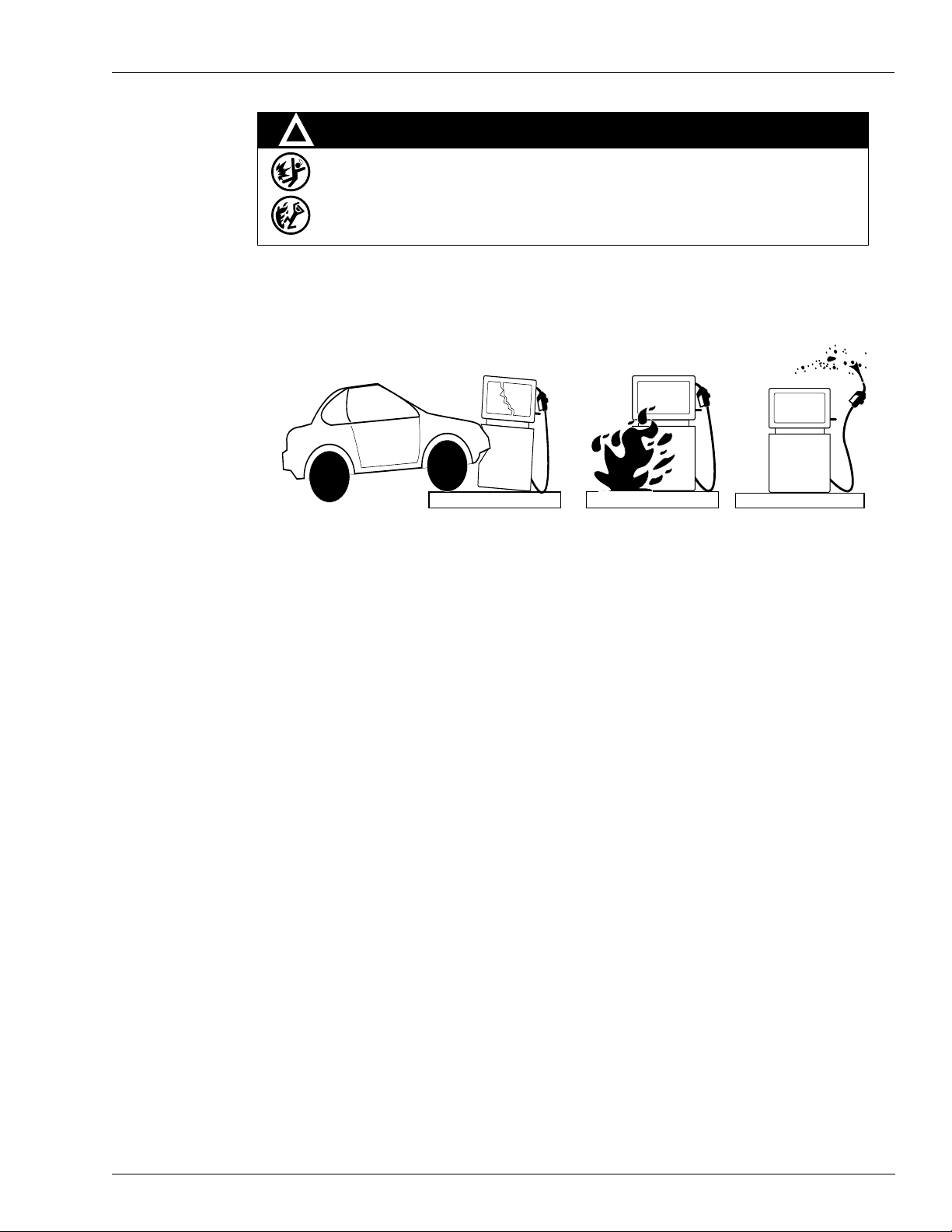
Hazards and Actions
!
WARNING
Spilled fuels, accidents involving pumps/dispensers, or uncontrolled fuel flow create a
serious hazard.
Fire or explosion may result, causing serious injury or death.
Follow established emergency procedures.
The following actions are recommended regarding these hazards:
Collision of a Vehicle with Unit Fire at Island Fuel Spill
• Do not go near a fuel spill or allow anyone else in the area.
• Use station EMERGENCY CUTOFF immediately. Turn off all system circuit breakers to the
island(s).
• Do not use console E-STOP, ALL STOP and PUMP STOP to shut off power. These keys do no t
remove AC power and do not always stop product flow.
• Take precautions to avoid igniting fuel. Do not allow starting of vehicles in the area. Do not allow
open flames, smoking or power tools in the area.
• Do not expose yourself to hazardous conditions such as fire, spilled fuel or exposed wiring.
• Call emergency numbers.
MDE-4616B 9120K and 9820K Series AST Pumps Service and Parts Manual · September 2008 Page 7
Page 12

This page is intentionally left blank.
MDE-4616B 9120K and 9820K Series AST Pumps Service and Parts Manual · September 2008 Page 8
Page 13

General Preventive Maintenance
3 – Preventive Maintenance
General
Gasboy pumps are designed and constructed to give many years of uninterrupted service. In
fact, operators report years of trouble-free operation with absolutely no service expense. Yet,
certain parts of a pump are bound to wear, and Gasboy therefore recommends a periodic
inspection, at least twice a year, for such things as fuel leaks, belt tension and condition,
lubrication and strainer cleanliness. If such a procedure is followed, any small adjustments that
are necessary can be made before expensive, annoying breakdowns occur. The result of this
sound approach is continuous, profitable service from all of your Gasboy equipment.
!
!
WARNING
To reduce the risk of electrical shock when servicing a pump, turn off all power to the
pump.
Hints for Better Pump Performance
Demand Competent Service
Gasboy suggests all service be done by certified Gasboy Authorized Service Contractors
(ASCs) trained and familiar with the service of Gasboy products. Warranty service must be
done by Gasboy ASC. Gasboy has a Distributor Network which services fuel dispensing and
management systems in every section of the country.
Use Gasboy Authorized Parts
Should excessive wear, rust, or corrosion of parts cause inefficient operation, it is always best
to replace them immediately; but if you want the best results and continuity of the
Underwriters’ Label on your pump, ensure that new authorized service parts supplied by
Gasboy are used. Every part of a pump is carefully designed for a particular purpose. If it is
replaced by an incorrect or substandard substitute, pump operation can be unsatisfactory and
warranty will be voided. Always use new gaskets or seals when se rvicing or rebuilding
Gasboy equipment; do not re-use the old ones.
MDE-4616B 9120K and 9820K Series AST Pumps Service and Parts Manual · September 2008 Page 9
Page 14

Preventive Maintenance Preventive Maintenance
Operate with Reasonable Care
Like any machine, the pump that is operated with reasonable care will last longer and give
better service. Abuse should be avoided (such as dropping the nozzle on the ground, operating
the unit with a dirty strainer, dragging the hose across the concrete island or driv eway, running
the pump with the nozzle closed for more than two minutes and so on). Parts that fail from
abuse will not be covered by warranty . The time and care given to your pumps will be returned
to you in the form of dependable service.
Preventive Maintenance
Refer to the “Important Safety Information” on page 5 and read and understand all the
information contained there. It is recommended that all service to this unit be done by
Certified Gasboy ASCs familiar with the operation of this equipment and safety requirements
for servicing equipment in potentially hazardous condition or location.
Keep Water Out
Water tends to collect in storage tanks. This is due to moisture-laden air being drawn into the
storage tank and condensing, or to defective fill openings that are not properly protected with
watertight covers. Storage tanks should be checked after every fill-up for water and removed
with a sump pump, to forestall serious damage to equipment. Water, sediment, and other
foreign matter that accumulates in the tank can be drawn up into the pump and cause failures.
Clean the Dial Face
Clean the dial face with a soft, clean, damp cloth as often as necessary. Do not use abrasive
cleaners or those containing ammonia.
Clean the Strainer
Clean the strainer immediately after the pump has been installed and tested, and again after a
few hundred gallons have been delivered. Thereafter, once every six months, or whenever a
filter is changed. The symptoms of a dirty or clogged strainer in a pump are slow delivery,
noisy operation, and pulsation. To clean the strainer, turn off AC power to the pump. Locate
the Suction Strainer Cap on the plumbing unit and unscrew it to access and remove the
strainer. Use compressed air to blow the dirt out of the strainer. Clogged strainers can
commonly be cleaned using alcohol. Refer to item 3 in the parts list under
on page 24.
!
!
“Meter Assembly”
CAUTION
Always wear protective safety goggles or glasses when using compressed air.
Page 10 MDE-4616B 9120K and 9820K Series AST Pumps Service and Parts Manual · September 2008
Page 15

Preventive Maintenance Preventive Maintenance
Change the Filter
If the unit is equipped with a filter, check and change it at regular intervals. A dirty filter in a
pump will cause a slower delivery rate. Refer to the accessories section of your parts manual to
ensure that you replace the filter with one designed for your model. Always use a drip pan
directly below the filter when removing the cartridge to prevent contamination of the soil and
to aid in fluid recovery. Refer to item 2 in the parts list under
“Meter Assembly” on page 24.
Power Reset External Adjustment
If the pump or remote dispenser fails to reset or shut off properly, the reset motor may need to
be adjusted. To adjust, proceed as follows:
1 Loosen the lock nut on the adjusting screw and back screw out until it stops.
2 Move the reset lever to the ON position.
3 Turn adjustment screw in until reset motor starts.
4 Advance adjustment screw an additional 1/2 to 3/4 turn. Hold screw in this position and
tighten the lock nut.
5 Move the reset lever to the OFF position, and then back to the ON position to verify if the reset
motor operates properly. The reset coupling should make one revolution and stop.
Adjustment Screw
Lock Nut
MDE-4616B 9120K and 9820K Series AST Pumps Service and Parts Manual · September 2008 Page 11
Page 16

Preventive Maintenance Preventive Maintenance
Adjust the Belts
With proper care, belts will give exceptionally good service. A loose belt not only cuts down
pumping speed, due to slipping, but also results in excessive wear.
On the 9X20K units, the belt can be tightened by removing a link from the belt.
Preserve the Finish of Your Pumps
Nearly all gasoline pumps are installed outdoors where their surfaces are subjected to the
action of the weather. As a result, it is necessary to give the finish a reasonable amount of care
if an attractive appearance is to be maintained.
The finish on Gasboy pump housings is a high-heat baked synthetic enamel, similar to that
used on automobiles. The life of this finish can be lengthened several years if, at regular
intervals, the painted surfaces are thoroughly cleaned with a non abrasive detergent and then
protected with a coat of paste wax.
• Do not use abrasive cleaners.
• Do not use high pressure spraying equipment.
• Fuel stains can be removed using “Greased Lightening”.
In order to retain the unmarked finish on stainless steel, occasional cleaning is required. In
corrosive atmospheres, such as coastal areas, a more frequent cleaning schedule is necessary.
• Under ordinary conditions, washing with deter gent or soap and water, followed by a clean
water rinse, is sufficient.
Note: If hard water is used, the surface should be wiped dry with a soft clean cloth to
prevent the formation of water spots.
• Marks or spots, such as grease, oily fingerprints and smudges which resist soap and
detergents, will have to be removed with a stronger cleaner capable of removing all oil/
grease completely (DO NOT use ordinary steel wool as iron particles may adhere to the
surface and cause corrosion.)
Note: Care should be taken in choosing a cleaner because any cleaning compounds or
powders which contain abrasives can scratch a mill-rolled finish. Care must be
exercised in their use to run in the direction of the polishing lines in the steel,
never across them.
After cleaning, an application of paste wax is recommended t o protect the surface and prolong
the interval between cleaning.
Page 12 MDE-4616B 9120K and 9820K Series AST Pumps Service and Parts Manual · September 2008
Page 17

Base and Motor Shaft Parts
4 – Parts
Base and Motor Shaft
16
1, 3
5
17, 18
7
15
6
Item # Part Description Current Part Previous Part Quantity
1 Conduit, Motor to J-Box M06978B001 - 1
2 Motors, Cont. Duty 61 Frame R14213-32 - 1
3 Assembly Conduit Motor to J-Box M07039B001 - 1
4 Electric Motor Frank In M01068B302 - 1
5 Assembly, Bottom Panel 9x20k M06582A001 - 1
6 Mounting Foot,9820 SS Tum 026401 - 4
7 Screw, Metric M8 X 18 M00417B009 - 8
8 Mount, Universal M04871B001 - 4
9 Washer, Flat M20 Stl Znpl M00959B019 - 4
10 Screw Metric M8 X 40 M00415B017 - 4
11 Belt Adjustable M07022B002 - 0.0255
12 Flat Washer M00959B008 - 4
13 Bracket, Reinforced Corner Gussett (Not Shown) M06757B002 - 2
8, 9, 10, 11, 12
2, 4
MDE-4616B 9120K and 9820K Series AST Pumps Service and Parts Manual · September 2008 Page 13
Page 18

Parts Base and Motor Shaft
Item # Part Description Current Part Previous Part Quantity
14 Nut, Metric, Hex Serrd Flg (M8) (Not Shown) M00414B003 - 4
15 Shelf, Motor Support M06566A001 - 1
16 Union, Conduit 1/2 Inch Q10016-04 - 1
17 Pulley A Belt 2.50 Pd R18900-27 - 1
18 Pulley A Belt 3.00 Pd R18900-32 - 1
Page 14 MDE-461 6B 9120K and 9820K Series AST Pumps Service and Parts Manual · September 2 008
Page 19

Pump Assembly Parts
Pump Assembly
3
1
9
2
7
10
5
11
6
4
6
8
MDE-4616B 9120K and 9820K Series AST Pumps Service and Parts Manual · September 2008 Page 15
Page 20

Parts Pump Assembly
Item # Part Description Current Part Previous Part Quantity
1 Global Pumping Unit M04920B003 - 1
2 Adaptor - EPZ Inlet 023146 - 1
3 Connection 90 Elbow Compression (Male) Q12503-02 - 1
4 Elbow 1-1 1/2 90 deg 150 PSI MI K46046 - 1
5 Lockwasher Metric M10 Zinc Plate M01071B001 - 3
6 Nipple FEe Pipe 1 1/2 x 6.00 R11493-28 - 2
7 O-Ring 2.237 x 0.103 Q10067-31 - 1
8 Pipe Union, Female K12179 - 1
9 Plate, Pump Mounting M06738B001 - 1
10 Screw Metric M8 X 16 M00415B009 - 4
11 Socket Head Cap Screw, M10 X 25 M04973B005 - 3
12 Tube, Vent 9x20K (Not Shown) M06650B003 - 1
GPU Repair Kits
13 Bypass Valve M04920K100 - 1
14 Strainer M04920K101 - 1
15 Master Seal M04920K102 - 1
16 Blades M04920K103 - 1
17 Control Valves M04920K104 - 1
18 Lip Seal M04920K105 - 1
19 Pumping Element Field Rebuild M04920K106 - 1
20 Sump Float - OIML (B005) M04920K107 - 1
21 Pumping Element Shop Rebuild M04920K108 - 1
22 Inlet Check Valve M04920K109 - 1
23 Overflow Check Valve M04920K110 - 1
24 Sump Float - Non OIML (B001) M04920K111 - 1
Page 16 MDE-4616B 9120K and 9820K Series AST Pumps Service and Parts Manual · September 2 008
Page 21

Meter Shelf, J-Box, and 9123 Register, Reset and Pulser Parts
Meter Shelf, J-Box, and 9123 Register, Reset and Pulser
Register
Junction Box
Pulser
Meter Shelf
CFT Meter
Assembled View
MDE-4616B 9120K and 9820K Series AST Pumps Service and Parts Manual · September 2008 Page 17
Page 22

Parts Meter Shelf, J-Box, and 9123 Register, Reset and Pulser
17
16
18
12
10 (Rear corners only)
1
7
2, 3, 4, 5, 8, 9, 13, 15 6
Exploded View
Item # Part Description Current Part Previous Part Quantity
1 Screw Hex Serr Flng Hd Q10253-02 - 3
2 Washr Lk Ext Th 1/4x.025 K50411-31 - 1
3 Stud Drive Gear N23567 - 1
4 Ball Swivel K93546-01 - 1
5 Pin Cotter 1/16x1/2 K02124 - 1
6 Mounting Bracket, Meter Shelf M06564A001 - 1
7 Screw, Metric M8 X 16 M00415B009 - 4
8 Gear Pinion 20 Th K55151-21 - 1
9 Assy Drv Gear & Bush 21 K55152 - 1
10 Bracket, Reinforced Corner M06757B002 - 2
11 Bracket Assy, Retriever (Not shown) M06768A002 - 1
12 Screw, Metric M8 X 18 M00417B009 - 13
Page 18 MDE-4616B 9120K and 9820K Series AST Pumps Service and Parts Manual · September 2 008
Page 23

Meter Shelf, J-Box, and 9123 Register, Reset and Pulser Parts
Item # Part Description Current Part Previous Part Quantity
13 Screw Skt Hd Cap 5/16-18 Q12081-02 - 1
14 Assy Drive Gear + Bushi K53743 - 1
15 Gear Pinion 12 Th K51008-24 - 1
16 Elbow Conduit 1/2 X 90 Male & Female K42448 - 1
17 Bushing, Reducing K49827-22 - 1
18 Union Conduit Male & Female 1/2 Q10016-04 - 1
Reset/Register Module
6, 23, 24
1, 5
8
Item # Part Description Current Part Previous Part Quantity
1 Drive Register Assembly 9120K, Gallons 022834 - 1
2 Nut Hex Keps W/ext Lkwshr Q12068-06 - 1
3 Screw Hex Hd Cap Finished K03782 - 1
4 Washer 5/16in Sae-n (.38 X K65235-33 - 1
5 Drive Register Assembly 9120K, Liters 022835 - 1
6 Reset Assy Elec Unli 115/ 048568 - 1
7 Dial-mask GB91501G001 - 1
8 Bracket-gear & Shaft- 912 014040 - 1
9 Sleeve S/b As 1463-3 056710 - 1
10 Nut Hex 5/16-18 Chk K01933 - 1
11 Shaft-reset Interlock-912 054510 - 1
12 Gear-60t(9120K Reset) 028235 - 1
7
MDE-4616B 9120K and 9820K Series AST Pumps Service and Parts Manual · September 2008 Page 19
Page 24

Parts Meter Shelf, J-Box, and 9123 Register, Reset and Pulser
Item # Part Description Current Part Previous Part Quantity
13 Washer, SS .260 X .500 068037 - 2
14 Brng Oilt Flng N17706-43 - 1
15 Groovpin 1/8x7/8 Ils#2zn2 013128 - 1
16 Washer, lock Ext 1/4 1114 068891 - 3
17 Screw Hex Hd Cap Finished K05287 - 3
18 Screw Tf Pnh Phl 4-40x Q11769-02 - 2
19 Ring Ret 1/4 K76238-41 - 1
20 Bracket Assy, Side Frame 9120K (Not Shown) M04295A001 - 1
21 Screw, Metric M8 X 18 M00417B009 - 2
22 Elbow Cndt 1/2x90 M & F K42448 - 1
23 Reset/reg Mod 9120K Gal 1 042724 - 1
24 Reset Assy Elec Unli 230/ 048677 - 1
Pulser Module
15
1, 17, 18
2
Item # Part Description Current Part Previous Part Quantity
1 Plsr 10:1 Vr 769780-010 021788 - 1
2 Bracket, Pulser Shaft M06740B001 - 1
3 Bearing Nyliner#4l2ff 011954 - 2
4 Gear Miter-24 T Mach Tank 028422 - 1
5 Pin Grv Type 1 3/32x5/8 K48724 - 1
6 Spirol Pin .062 X .750 Q10038-30 - 1
7 Screw Hex Hd Cap Finished K05287 - 2
8 Washer, lock Ext 1/4 1114 068891 - 2
9 Shaft-totalizer-9120K 054526 - 1
10 Spirol Pin .052 X .375 Q10038-26 - 1
6
9
Page 20 MDE-4616B 9120K and 9820K Series AST Pumps Service and Parts Manual · September 2 008
Page 25

Meter Shelf, J-Box, and 9123 Register, Reset and Pulser Parts
Item # Part Description Current Part Previous Part Quantity
11 Washer, SS .260 X .500 068037 - 1
12 Screw, Metric M8 X 18 M00417B009 - 2
13 Coupling-totalizer 9120K 054527 - 1
14 Spirol Pin .078 X .437 Q10038-35 - 1
15 Elbow Cndt 1/2x90 M & F K42448 - 1
16 Nipple Cndt 1/2 X 10-1/2 (Not Shown) R11976-80 - 1
17 Pulser Mod 9120K C+10:1 042737 - 0
18 Plsr 100:1 Vr 767181-332 047648 - 1
MDE-4616B 9120K and 9820K Series AST Pumps Service and Parts Manual · September 2008 Page 21
Page 26

Parts Meter Shelf, J-Box, and 9123 Register, Reset and Pulser
Junction Box Assembly
4
M07040A001
M07040A002
12
5
3
1
11
2
M07040A003
Page 22 MDE-4616B 9120K and 9820K Series AST Pumps Service and Parts Manual · September 2 008
Page 27

Meter Shelf, J-Box, and 9123 Register, Reset and Pulser Parts
Item # Part Description Current Part Previous Part Quantity
1 Junction Box M04480B010 - 1
2 Bracket, J-Box Mounting M06649B001 - 1
3 Bushing, Reducing 3/4 - 1/2 K49827-22 - 2
4 Conduit, J-Box to Reset M07002A001 - 1
5 Elbow, 1/2 X 90 M X F K42448 - 4
6 Pipe Plug C-Sunk 1 K51440 - 1
7 Pipe Plug C-Sunk 1/2 K43850 - 1
8 Pipe Plug C-Sunk 3/4 K57624 - 4
9 Screw, Hex, Sltd, Thd Frng, Wshr Hd (10-32 X 1/2) K85736-05 - 1
10 Screw TF, Hex Whsr Hd M X 18 M00417B009 - 2
11 Union Conduit 1/2 Inch Q10016-04 - 3
12 Expansion Union (conduit) N16289-20 - 1
13 Cover Junction Box M04536B010 - 1
MDE-4616B 9120K and 9820K Series AST Pumps Service and Parts Manual · September 2008 Page 23
Page 28

Parts Meter Shelf, J-Box, and 9123 Register, Reset and Pulser
Meter Assembly
1
2
7
Assembled View
Item # Part Description Current Part Previous Part Quantity
1 CFT Meter Assembly T20150-G9
2 2- Stage Sol Valve and Filter Manifold M04607B002
3 Strainer Insert High Capacity R19457 - 1
4 Assy Meter Check Valve N23619-G2 - 1
5 O-Ring 1.234 X 0.139 Q10068-09 - 1
6 O-Ring 1.609X 0.139 Q10068-14 - 1
7 Fitting, Discharge M04624B040 - 1
8 O-Ring 0.862 X 0.103 N16891-32 - 1
9 Screw Metric M8 X 25 M00415B011 - 2
10 Bolt, Hx Hd Sems, 5/16-18x1” Lg Q10865-36 - 4
Exploded View
- 1
T20150-G10
- 1
M04607B001
Page 24 MDE-4616B 9120K and 9820K Series AST Pumps Service and Parts Manual · September 2 008
Page 29

9823 Pulser, Totalizer and Gear Train Parts
9823 Pulser, Totalizer and Gear Train
Assembled View
Exploded View
28
33
25
26
Item # Part Description Current Part Previous Part Quantity
1 Assy, Pulser Mtg Bracket M07175A001 - 1
2 Nut, Metric Serrated M00414B002 - 4
3 Kit-Totalizer, 9820 Gal Factory 025934 - 1
4 Assy, Bracket Ast Totlzr M06737A001 - 1
5 Screw, Metric M8 X 18 M00417B009 - 2
24
31
11
34 35
Shelf Cutaway
1
4
8, 10
MDE-4616B 9120K and 9820K Series AST Pumps Service and Parts Manual · September 2008 Page 25
Page 30

Parts 9823 Pulser, Totalizer and Gear Train
Item # Part Description Current Part Previous Part Quantity
6 Tie Cable Q10178-02 - 2
7 Kit-Totalizer 9820 Ltr Factory 025936 - 1
8 Assy, Brkt Gear Train M07102A001 - 1
9 Nut, Metric Serrated M00414B002 - 4
10 Assy, Brkt Gear Train M07102A002 - 1
Vapor (Shown)
11 Nippl 3/4 X 6-1/2 Lg R11496 70 - 1
12 Assy, Feedline Tube M06810A001 - 1
13 Flange Pump Discharge M04686B001 - 1
14 Ring 0 1-1/8x1-3/8x1/8 Q10068-07 - 1
15 Screw Skt Hd Cap Metric M04973B001 - 2
16 Screw Hex Serr Flng Hd Q10253-02 - 4
17 Ring O 1-1/4x1-1/2x1/8 Q10068-09 - 2
18 Assy, Discharge Tube M06809A001 - 1
19 Assy, Bracket U-bolt Mtg M06767A001 - 1
20 Brakt U-bolt Mounting M06767B002 - 1
21 U-bolt, Metric, M8 M00703B001 - 2
22 Nut, Metric M8 Serrated M00414B003 - 6
23 Screw, Metric M8 X 18 M00417B009 - 6
24 Nipple 3/4 X 3-1/2 R11496-75 - 1
25 Nipple 3/4 X 4-3/8 Lg R11496-84 - 1
26 Elbow-3/4 X 90 (Paint) 024955 - 1
27 Label Gasboy V/r Hose M04039B003 - 1
28 Casting Splitter Vp Emco# 049980 - 1
29 Elbow Cndt 1/2x90 M & F K42448 - 1
30 Condt, J-box To Valve M07001B001 - 1
31 Screw Hex Hd Wshr Hd T-t K85736-51 - 4
32 Screw, Metric M8 X 16 M00415B009 - 2
33 Elbow St 3/4 X 90 Mi K21703 - 1
34 Bushg Red Hex Hd K02297 - 1
35 Bracket, Vapor Casting M06741B001 - 1
Non Vapor
36 Nippl 1x10⁻³/4 R11495-24 - 1
37 Condt, J-box To Valve M07001B001 - 1
38 Screw, Metric M8 X 16 M00415B009 - 2
Page 26 MDE-461 6B 9120K and 9820K Series AST Pumps Service and Parts Manual · September 2 008
Page 31

Panels, Remote Register, Mounting Kits Parts
Panels, Remote Register, Mounting Kits
9123K
7
24
5
17
15
16
3
2
4
8
10
11
9
19
12
26
18
14
13
1
6
25
Item # Part Description Current Part Previous Part Quantity
1 Assy, Front Panel 9120K M06583A002 - 1
2 Glass Window 9120K 028811 - 1
3 Brakt 9120K Totalizer Face M06739B001 - 1
4 Panel Lh Side 9120K M06584B002 - 1
5 Panel Back 9x20K M06578B0 03 - 1
6 Panel Rh Side 9X20K M06579B002 - 1
7 Assy, Top Panel 9X20K M06758A001 - 1
8 Cover Nozzle Boot 9120K 026420 - 1
9 Screw Tc Pnh Phl 10-32 X Q11769-76 - 6
10 Brkt Nozzle Boot Mtg 026403 - 1
11 Boot-noz;98a,88b/d (Mach) 003338 - 1
12 Screw Tpt Phil Fl Hd 8-32 Q13399-03 - 4
MDE-4616B 9120K and 9820K Series AST Pumps Service and Parts Manual · September 2008 Page 27
Page 32

Parts Panels , Remote Register, Mounting Kits
Item # Part Description Current Part Previous Part Quantity
13 Bracket Nozzle Boot 026421 - 1
14 Guide-nozzle 9120 029027 - 1
15 Bracket Lever Reset 9120K 033992 - 1
16 Bushing Lever Reset 9120K 017234 - 1
17 Stop-eccentric Plastic 063204 - 1
18 Washer,.264 X .500 X .030 N16599-123 - 1
19 Screw Rd Hd Phil 8-32x1/2 Q11560-53 - 1
20 Nut Hex Slf Lock 5/16-18 Q10218 10 - 2
21 Nut, Metric, Flange M00414B005 - 4
22 Nut, Metric Serrated M00414B002 - 8
23 Rivet 047211 - 2
24 Cap Plug 2" Blk Plastic Q10554-16 - 1
25 Plug Cap Plastic Q10554-06 - 1
26 Screw Hex Serr Flng Hd Q10253-02 - 4
27 Nut 1/2 Conduit Seal K89681 - 1
28 Hook-Noz; 87, 88B/D, 91 (Mach) 003732 - 1
29 Grommet, .875 OD X .375 N15941-42 - 1
30 Pin GRV Type 5 1/8X1 K63742 - 1
31 Cover Nozzle Boot BTM 026419 - 1
32 Grommet DSCH-3/4” 028930 - 1
Page 28 MDE-461 6B 9120K and 9820K Series AST Pumps Service and Parts Manual · September 2 008
Page 33

Panels, Remote Register, Mounting Kits Parts
9823K
5
1
3
8
Item # Part Description Current Part Previous Part Quantity
1 Panel RH Side 9X20K M06579B002 - 1
2 Panel LH Side 9820K M06581B002 - 1
3 Panel Back 9X20K M06578B003 - 1
4 Assembly, Front Panel 9820K M06580A002 - 1
5 Assembly, Top Panel 9X20K M06758A001 - 1
6 Window, Totalizer 9 Digit 069076 - 1
7 Nut, Metric, Flange M00414B005 - 2
8 Lock-Door w/Clip (2” CAM) 035017 - 2
9 Plug Cap Plastic Q10554-06 - 1
10 Grommet, .875 OD X .375 N15941-42 - 1
11 Nut, Metric Serrated M00414B002 - 8
12 Cap Plug 2” Blk Plastic Q10554-16 - 1
13 Grommet Dsch -3/4” 028930 - 1
4
6
7
2
MDE-4616B 9120K and 9820K Series AST Pumps Service and Parts Manual · September 2008 Page 29
Page 34

Parts Panels , Remote Register, Mounting Kits
Remote Register - Front View
Item # Part Description Current Part Previous Part
1 115 V Register (9823K) C06676 2 230 V Register (9823K) C06715 -
Page 30 MDE-4616B 9120K and 9820K Series AST Pumps Service and Parts Manual · September 2 008
Page 35

Panels, Remote Register, Mounting Kits Parts
Remote Register - Side View
1
8
2, 3
6, 7
11
4
5
9
10
Item # Part Description Current Part Previous Part
1 Panel, Top Cover, 9820 Register 040996 2 Stop C09585 3 Cushion Sleeve C09584 4 Lever, Control, 9820 Mach 003771 5 Housing Weld Assy. 040999 6 Hood 029416 7 Hood, Support Assembly 063507 8 Bearing Plate Assembly 045988 9 Cover 015760 10 Bracket, Tamper Proof 015694 11 Roll Pin, 1/8 X 1-3/8 (Not Shown) 042657 -
MDE-4616B 9120K and 9820K Series AST Pumps Service and Parts Manual · September 2008 Page 31
Page 36

Parts Panels , Remote Register, Mounting Kits
Remote Register Chassis Assembly - Top View
1
12
2
11
3
4
5
6, 7
Item # Part Description Current Part Previous Part
1 Weld Assy., Chassis C35584 2 PCB Assy., CPU 120 VAC C06394 3 Reflector, LCD Backlight C35399 4 PCB Assy., LCD Display C06387 5 Bracket Assy., Display Door C35543 6 Cable Assy., Totalizer w/ Bracket C06673 7 Actuator, Totalizer (Not Shown) C01342 8 IC RAM 2K X 8 C01383 9 PCB Assy., LED Backlight C06372 10 Cable Assy., Display/Power Supply C06668 11 Cable Assy., Ground Strap C06454 12 Cable Assy., DC Power C06679 -
8
10
9
Page 32 MDE-4616B 9120K and 9820K Series AST Pumps Service and Parts Manual · September 2 008
Page 37

Panels, Remote Register, Mounting Kits Parts
Remote Register Chassis Assembly - Front View
1
2
3
9
5
8
7
4
6
Item # Part Description Current Part Previous Part
1 Weld Assy, Chassis C35584 2 Cable Assy., DC Power C06679 3 PCB Assy., PS w/o Battery, 115V C06396 4 Bracket Assy., RH Hinge C35538 5 Relay Assy. C06681 6 Cable Assy., 5-pos. TB C06674 7 Cable Assy., 10-pos. TB C06675 8 Fuse Holder, Quick Conn. C09546 9 Bracket Assy., LH Hinge C35539 -
MDE-4616B 9120K and 9820K Series AST Pumps Service and Parts Manual · September 2008 Page 33
Page 38

Parts Panels , Remote Register, Mounting Kits
Remote Register Mounting Option
1
2
3
Item # Part Description Current Part Previous Part
1 Bracket Housing Mounting 042073 2 Weld Assembly, Pedestal Body 042080 3 Cover 042081 4 Side Mounting Bracket (not shown) 015128 5 Rear Mounting Bracket (not shown) 015127 -
Page 34 MDE-4616B 9120K and 9820K Series AST Pumps Service and Parts Manual · September 2 008
Page 39

Series Kits and Accessories Parts
Series Kits and Accessories
Part No Description
003043 Adapter, 9122, 3/4” NPT inlet and outlet
003044 Adapter, 9123, 1” NPT inlet and outlet
MDE-4617 Ast Totalizer Kit, Installation Instructions
MDE-4618 Ast Pulser Kit, Installation Instructions
MDE-4619 Ast Vapor Recovery Kit, Installation Instructions
M07087K001 Ast Pulser Kit; 10:1 Ratio
M07087K002 Ast Pulser Kit; 100:1 Ratio
M07087K003 Ast Pulser Kit; 1:1 Ratio
M07091K001 Ast Totalizer Kit; Gallons
M07091K002 Ast Totalizer Kit; Liters
M07425K001 Ast Adapter Kit; K-version
M07494K001 Ast Vapor Recovery Kit; 9820; K-version
M07494K002 Ast Vapor Recovery Kit; 9820 Vapor Complete
M07494K003 Ast Vapor Recovery Kit; 9120 Vapor Complete
M07494K004 Ast Vapor Recovery Kit; 9120; K-version
Other Options
R18189-10
R18189-30
R18896-G1
026019
030456
030457
C06718 CFN/TOPKT RS-485
C06717 Single Pulse Output
C06722 Dual Pulse Output
C05818 Resistor Assembly
C06683 Resistor Assembly
049043 Vapor Recovery Kit
032600 High Hose Retriever
Filter Type
Extra Length Hoses
MDE-4616B 9120K and 9820K Series AST Pumps Service and Parts Manual · September 2008 Page 35
Page 40

Spirol® is a registered tradema rk of Spirol International Holding Corporation. TopKAT TM is a trademark of Gasboy International. UL® is a registered
trademark of Underwriters Laboratories Inc.
© 2008 GASBOY
7300 West Friendly Avenue · Post Office Box 22087
Greensboro, North Carolina 27420
Phone 1-800-444-5529 · http://www.gasboy.com · Printed in the U.S.A.
MDE-4616B 9120K and 9820K Series AST Pumps Service and Parts Manual · September 2008
 Loading...