

Page 1
PULSER KIT INSTRUCTIONS, 9120/7520
This instruction sheet shows how to install the 10:1/100:1 Pulser Kit for 9120/7520. Be sure to follow all warnings
and safeguards as outlined in the enclosed Warnings and Safeguards sheet before working on the unit.
Kit Contents (10:1 Pulser Kit 025929; 100:1 Pulser Kit 025930)
P/N Description Qty
015451 Bracket, Pulser, 9120 1
051790 Screw, ¼-20x ½ HHC 2
068891 Washer, Lock, ¼ 1114 2
021788 Pulser, 10:1 VR (025929 only) 1
047648 Pulser 100:1, VR (025930 only) 1
054827 Shaft-Drive Pulser 1
025015 Elbow, Conduit ½ x 45 M/F 1
025045 Elbow, Conduit ½ x 90 M/F 1
021372 Conduit, ½ x 4-½ 1
053625 Screw, 6-32 x 3/8, Pn Hd 3
066400 ½ UNY Explosion Proof Conduit Union 1
039130 Nut, Conduit Lock 1
022050 Conduit, Pulser to Frame 1
P/N Description Qty
003515 Junction Box Cover 1
003340 Junction Box 1
042290 Pin, Cotter, 3/64 x ½ 2
034715 Link-Drive Pulser 1
053000 Screw, 10-32 x 3/8 2
Z09273 Nut, Hex Keps #10-32 2
022431 Gear Train, Top 1
022432 Gear Train, Bottom 1
034709 Link, Computer-Drive 1
042130 Pin, Groove, 1/8 x 5/8 2
021058 Conduit Fitting, 90 M/F 1
021986 Coupling, ½ Conduit 1
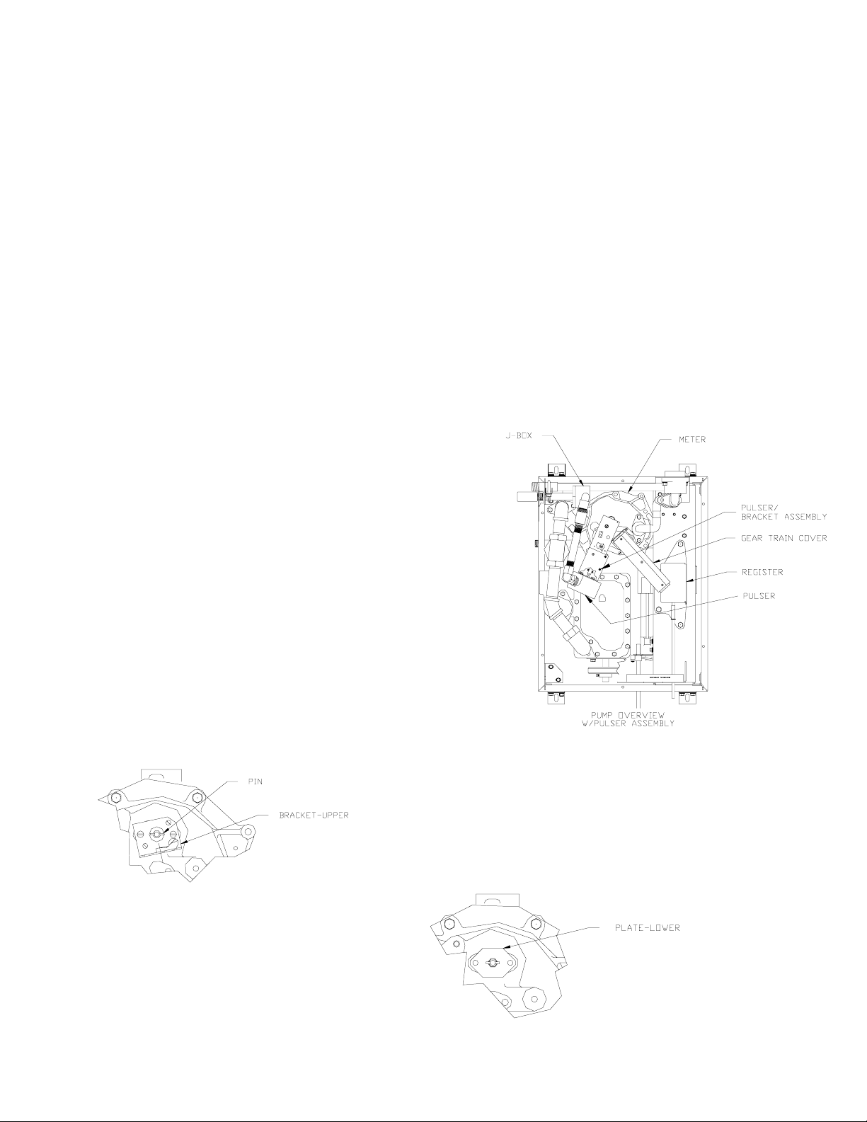
1. Remove screw that ho lds gear tr ain cover to reg ister and set
aside.
2. Remove screw on other end of gear train cover fastened to
bracket and set aside.
3. Remove and set aside gear train cover.
4. Remove brass link-drive fr om meter; this part will not be reused.
5. Knock out pin from meter shaft and discard.
6. Remove and discard 2 screws securing bracket to meter.
Remove upper bracket; reserve for later use.
7. Remove two screws and remove retaining plate
from meter (see illustration for Steps 10-12 for
retaining plate location).
032006 Rev. 9223 Page 1
Page 2
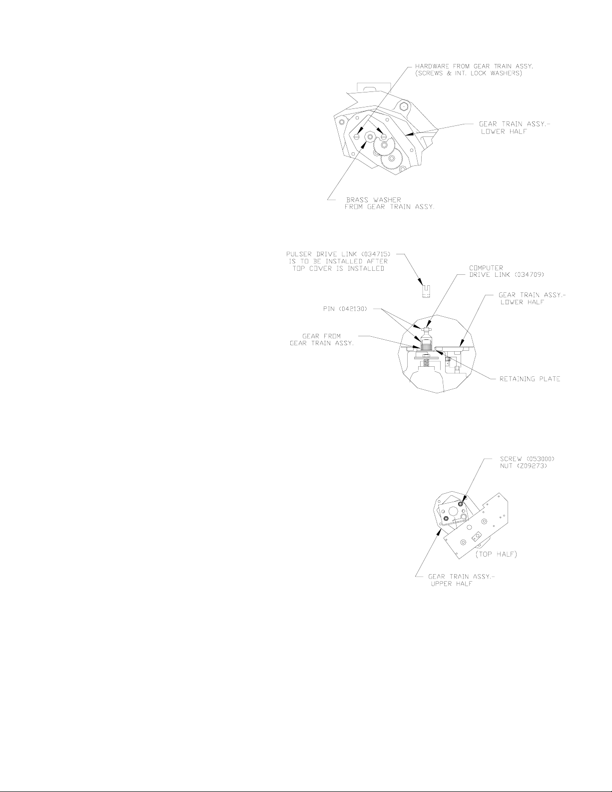
8. Install lower half of gear train assembl y, 022432, using
supplied screws and lock washers.
9. Install one brass washer (supplied with gear train
assembly) to gear train assembly.
10. Install gear (supplied with gear train
assembly) on top of brass washer.
11. Assemble one 042130 pin into 034709 linkdrive.
12. Install 034715 link-drive to gear from gear
train assembly with other 042130 pin .
13. Assemble existing bracket (from Step 6) to 022431 gear train top with
053000 screws and Z0 9273 nuts. NOTE: Remove greas e and shavings
from cover of gear train.
14. Assemble gear train top to gear train bottom with four screws supplied.
15. Install 034709 brass link to pinned link-drive.
16. Re-install gear train cover set aside in Step 3, aligning pins from cover
with brass links on meter and register. Once in place, assemble using
existing hardware reserved from Steps 1 and 2.
Continued on the next page
032006 Rev. 9223 Page 2
Page 3

Refer to the following diagram for Steps 17-31.
17. Remove cap from totalizer drive and install cotter pin.
18. Install drive shaft 054827 to pulser with cotter pin.
19. Install bracket to pulser with screw 051790 and washer 068891.
20. Remove red thread protector cap from pulser and wires.
21. Install 025015 elbow into pulser (grease threads).
22. Install 025045 elbow to 025015 elbow (grease threads)
23. Install 015451 pulser bracket to gear train with three 053625 screws.
24. Assemble 021372 conduit to 025045 elbow (grease threads).
25. Assemble 066400 conduit union to 021372 conduit (grease threads).
26. Assemble 021058 conduit fitting to 066400 conduit union.
27. Assemble 003340 J-box to 021058 conduit fitting.
28. Assemble 003515 J-box cover to 003340 J-box.
29. Assemble 022050 conduit to 003340 J-box.
30. Assemble 039130 nut to end of 022050 conduit.
31. Assemble 021986 coupling to 022050 conduit.
032006 Rev. 9223 Page 3
 Loading...