

Page 1

SERIES 9100A
PUMPS AND DISPENSERS
INSTALLATION/OPERATION
MANUAL
035257
REV. 03/07/03
INSTALLERS - IMPORT ANT
In addition to installation information, this manual contains warnings, safeguards
and proced u res on the u se and care of th e Series 9100A pumps. Please leave this
manual with the pump owner after the installation is complete.
The information in this document is confidential and proprietary. No further disclosure shall be made without
permission from Gasboy International LLC. Gasboy International LLC believes that the information in this
document is accura te and reliable. However, we assume no responsibility for it s use, nor f or any infringem ents of
Copyright 2003 by Gasboy Internat ional LLC All rights reserved.
Page 2

patents or other rights of third part ies resulting from its use. We reserve the right to make changes at any time
without notice.
GASBOY INTERNATIONAL LLC LANSDALE, PA
Page 3

Gasoline and petroleum products are flammable. To avoid injury or death to persons or damage to equipment or
property, follow these listed warnings and other warnings and precautions outlined in this manual when installing,
using, or working around this equipment. Check with GASBOY Technical Services for compatibility of liquids with
pump material s.
TURN OFF AND LOCK OUT ALL PO W ER TO PUMP BEFORE PERFORM ING SERVICE, M AINTENANCE OR IN THE EVENT
All products must be installed by a
qualified installer and used in
conformance with all building, fire, and
environmental codes and other safety
requirements applicable to its
installation and use, including, but not
limited to, NFPA 30, NFPA 30A, NFPA
395 & NFPA 70. A qualified installer is
familiar with fuel systems installations
under the above stated building, fire,
and environmental codes and other
safety requirements for the particular
type of installation.
This product is only part of a fuel
dispensing system and additional
equipment and accessories, such as,
but not limited to, breakaway
connectors, shear valves, pressure
regulators, flow limiters, and other
safety devices may be necessary to
meet the applicable codes.
For maximum safety, we recommend
that all em ployees be trained as to the
location and procedure for turning off
power to the entire system.
Instructions regarding proper operation
of the equipment along with the
appropriate safety warnings should be
posted in plain view at the fuel island.
Before performing service or
maintenance (including changing of fuel
filters or st rainers) or in the event of a
fuel spill, turn off and loc k out all power
to the system. In battery-powered
pumps, disconnect power source. In
submersible pump applications, tur n off
and lock out power at the master panel
and close any impact valves to the
submersible pump and any other
dispensers which use that submersible
pump. AC power can feed back into a
shut-off dispenser when dispensers
share a common submersible pump or
starter relay. Also block islands so no
IMPORTANT WARNINGS AND SAFEGUARDS
OF A FUEL SPILL.
vehicles can pull up to the dispenser
when the dispenser is being worked on.
DO NOT use Teflon tape for any pipe
threads in the product.
DO NOT use consumer pumps for
pumping fuel or additives into aircraft.
DO NOT use commercial pumps for
direct fueling of aircraft without filters
and separators necessary to ensure
product purity.
DO NOT use where sanitary design is
required (for food products for human
consumption) or with water-based
liquids.
DO NOT smoke near t he pum p or when
using the pump.
DO NOT use near open flame or
electrical equipment which may ignite
fumes.
DO NOT permit the dispensing of
gasoline or other petroleum products
into a vehicle with its motor running.
DO NOT permit the dispensing of
gasoline or other petroleum products
into unapproved containers or into
approved containers in or on vehicles
including trucks. All containers must be
filled on the ground to prevent static
discharge. Always use Approved and
Listed hoses and nozzles with electric
pumps and dispensers.
DO NOT block open the nozzle in any
manner. Nozzles shall conform to UL
and NFPA code requirements for
attended or unattended ser v ice.
DO ensure that the pump is equipped
with proper filters based on the product
being dispensed and its intended use.
DO wear safety goggles and protective
clothes when dispensing any liquid
which may be potentially harmful or
hazardous.
035282 Rev. 1267
GASBOY INTERNATIONAL LLC
707 North Valley Forge Rd. Lansdale, PA, 19446 ● (215) 855-4631 ● FAX: (215) 855-0341
Page 4

DO keep all parts of body and loose
clothing clear of belts, pulleys, and
other exposed moving parts at all times.
DO require washing and changing of
clothes if fuel is spilled on a person or
his/her clothing. Keep away from open
flames, sparks, or people smoking.
DO provide a receptacle for catching
product from pump/meter when
servicing.
DO clean up product spills on the
driveway. Turn off and lock out all
power prior to cleanup.
DO insure pump is properly grounded.
DO insure hose is compatible with fluid
being dispensed.
DO inspect hose, nozzle, and pump on
a regular basis for wear, damage, or
other conditions which may create a
safety or environmental hazar d.
DO make sure all pipe threads are
properly cut and the inside reamed to
remove burrs. Use UL classified
gasoline-resisting compound on all
joints of gasoline handling piping.
Sealing compound must also be
resistant to Gasohol (Ethanol and
Methanol). Use gasoline-resistant pipe
compound on male threads only; pipe
compound used on f emale threads can
be squeezed into the supply line where
it can enter the product stream and
become lodged in the pump or meter .
DO ensure that junction box covers ar e
in place and properly tightened. Mating
surfaces between the box and cover
must be free of dirt, nicks, and
scratches. All unused entries into the
junction box must be properly plugged.
Page 5

CONTENTS
IMPORTANT WARNINGS AND SAFEGUARDS FOR COMMERCIAL PUMPS
Section 1: INTRODUCTION
Purpose................................................................................................. 1-1
General Description............................................................................... 1-1
Section 2: INSTALLATION
Installation Precautions.......................................................................... 2-1
Foundation ............................................................................................ 2-2
Suction Pump........................................................................................ 2-2
Remote Dispenser................................................................................. 2-2
Nozzle, Hose, and Ac cessories ............................................................. 2-3
Supply Line ........................................................................................... 2-3
Single Pump/Remote Dis penser Dimensions......................................... 2-4
Twin Pump/Remot e Dis penser Dimensions ........................................... 2-5
9140A Remote Dispenser Dimens ions................................................... 2-6
011865 Base Layout.............................................................................. 2-7
011873 Base Layout.............................................................................. 2-8
011887 Base Layout.............................................................................. 2-9
011888 Base Layout.............................................................................. 2-10
011892 Base Layout.............................................................................. 2-11
011894 Base Layout.............................................................................. 2-12
011898 Base Layout.............................................................................. 2-13
011971 Base Layout.............................................................................. 2-14
011972 Base Layout.............................................................................. 2-15
011981 Base Layout.............................................................................. 2-16
Section 3: CONTROL LINES
Purpose................................................................................................. 3-1
Grounding ............................................................................................. 3-1
Reset Motor Feed.................................................................................. 3-1
Pump Motor Feed.................................................................................. 3-1
Return................................................................................................... 3-2
Submersible Feed, S ubmersible Drive................................................... 3-2
Reset Complete (Switch Detect)/Slow Flow........................................... 3-2
Fast Flow .............................................................................................. 3-2
Light Feed............................................................................................. 3-2
Light Neutral.......................................................................................... 3-2
Phase 2 Feed........................................................................................ 3-2
Pulser.................................................................................................... 3-2
Section 4: WIRING
Wiring Precautions................................................................................ 4-1
Wiring Precautions................................................................................ 4-2
Grounding ............................................................................................. 4-2
Circuit Breakers..................................................................................... 4-2
The Pump Motor.................................................................................... 4-2
Motor Amp Ratings................................................................................ 4-2
Wire Size............................................................................................... 4-3
03/07/03 Contents-1
Page 6

GASBOY Series 9100A
Conduit.................................................................................................. 4-4
Wiring Diagrams.................................................................................... 4-5
024212 Wiring Diagram (9152AX , 9153AX, 9140AX)............................. 4-6
024213 Wiring Diagram (9152AX TW1 & 2; 9153AXT W1 & 2)................ 4-7
024214 Wiring Diagram (215A/9152AX, 9153AX; 216A /9153AX)........... 4-8
024222 Wiring Diagram (9152ATW2, 9153ATW 2, 9153ATW1M)........... 4-9
024223 Wiring Diagram (9152ATW1) .................................................... 4-10
024224 Wiring Diagram (9152A, 9153A)................................................ 4-11
024225 Wiring Diagram (9153AHC, 9140)............................................. 4-12
024320 Wiring Diagram (215AZ/9152AX, 9153AX; 216AZ 9153AX,
9140AX ) ( Front Load Satellite).......................................................... 4-13
Section 5: PULSERS
General ................................................................................................. 5-1
Wiring.................................................................................................... 5-1
Reed Pulsers......................................................................................... 5-2
Electronic Pulsers.................................................................................. 5-3
Section 6: START-UP
Completion Checklist............................................................................. 6-1
Start-Up................................................................................................. 6-1
Post Start-Up Tests............................................................................... 6-2
Voltage............................................................................................. 6-2
Tightness ......................................................................................... 6-2
Belts................................................................................................. 6-3
Calibration........................................................................................ 6-3
Power Reset External Adjustment ......................................................... 6-3
Section 7: OPERATING SEQUENCE
Pump .................................................................................................... 7-1
Remote Dispenser................................................................................. 7-1
Section 8: PREVENTIVE MAINTENANCE
General ................................................................................................. 8-1
Hints for Better Pump Performance....................................................... 8-1
Demand Com petent Service............................................................. 8-1
Use Authorized Parts........................................................................ 8-1
O per ate with Reasonable Care......................................................... 8-2
Preventive Maint enanc e Check List....................................................... 8-2
Keep Water Out ............................................................................... 8-2
Pump Lubrication.............................................................................. 8-2
Meter Lubrication.............................................................................. 8-2
Hose Retrievers................................................................................ 8-2
Keep the Non-Computer Lubricated.................................................. 8-3
Dial Face.......................................................................................... 8-3
Cleaning t he S trainer........................................................................ 8-3
Filter................................................................................................. 8-3
Cleaning By - pas s and Regulating Valve Assemblies......................... 8-4
Adjusting the Belts – Suction Pumps Only........................................ 8-4
Preserve the Finish of Your Pumps .................................................. 8-4
Contents-2 03/07/03
Page 7

Section 1
INTRODUCTION
PURPOSE
The GASBOY Series 9100A Pumps and Dispensers Installat ion/Operat ion Manual is pr ovided t o
assist the installer in installing and operating the unit. This manual should be supplied to the
electrician pr ior to the installation of conduit and wiring to ensure the Series 9100A dispensing
unit is installed properly . Faulty inst allations are the major c ause of unit malfunct ions. The unit
must be installed and operated as described in t his manual to ensure the reliability and pr oper
operation of the Ser ies 9100A dispensing unit . In addition to installation information, this manual
contains warnings, s afeguards and procedures on t he use and care of the Series 9100A pumps
and remote dispensers . Be sure to leave this manual wit h the pump/dispenser owner after the
installation is complete.
☎ Customers and installers having any questions pertaining to the installation should
contact their GASBOY distribu t or.
GENERAL DESCRIPTION
The GASBOY Series 9100A dispensing unit s are UL-listed and are available in a self-contained
(suction pump) pac kage or in a remote-controlled (dispenser) package. Both packages offer a
variety of m odels which are available as single hose outlets or dual hose outlets (with single or
dual product capability). The self-contained models are available in standard speed, up to 15
GPM/56 LPM; in high speed, up to 22 G PM/ 83 LPM; or in a single hose model with high capacity
speed, up to 26 GPM/ 99 LPM. The rate of delivery for the remote- controlled pack ages will vary
according to t he s ize of t he s ubmersible pum p. T he delivery r ate of both pac kages will also v ary
depending upon installation conditions and added accessories.
All models of the Series 9100A offer mechanical non-computers complete with electric resets.
Mechanical pump register s show the total v olume for a delivery. A ll non-computers will read up
to 999.9 gallons or liter s .
Other feat ur es and specifications of the Series 9100A are:
• Hose hangers.
• Discharge elbows.
• A 12-foot Listed gasoline hose assembly.
• A working voltage of 115 VAC, 60 Hz. for domestic units or 230VAC, 50 Hz. or 60 Hz. for
international use.
• Mechanical volume totalizers for each hose outlet.
03/07/03 1-1
Page 8

GASBOY Series 9100A
• Separate contr ol lines to allow individual control of each hos e outlet if desired.
1-2 03/07/03
Page 9

GASBOY Series 9100A
• A Reset Complete (s witch detect ) and opt ional pulser outputs which allow monit oring of the
register's operation when it is connected to an automated fuel management syst em.
• Unions are provided at t he inlet of all suction pumps and r em ote dispensers.
• All models exc ept the high flow units us e a quiet and efficient gear pump which features an
air eliminator, built into the pump casting. The pump meter is a three piston, positive
displacement m eter which is test ed and calibrated for accuracy at any speed or press ure up
to the maximum wor k ing pr es s ur e of 50 psi (3.45 Bar).
The high flow model uses a vane- type pump with a separate air elim inator. The pump meter
is a 1 1/2" (38.1mm), six-step, rotary motion, positive displacement unit.
• The st andard cabinet finish is top, s ides, and bezel painted black while the front and back
panels are painted white.
• The height of the cabinet s is 52-5/8" (1336.7mm). The other dimensions may be found in
Section 2 of this m anual and on the single sheet base layout for each model.
• Available options and accessories for the GASBOY Series 9100A dispensing units include
Listed automatic nozzles, light s, high/low s lowdown valves, pulser s, special lengt hs of Listed
hose, List ed dual swivels, internal hos e r etrievers, filters, front and bac k pump panels painted
to the color specified by the customer, stainless steel panels, Listed emergency shutoff
valves, satellite piping, top mount t i c k et printer, and elect r ic k ey trol and hand cranks.
Contents-2 7120
Page 10

Page 11

Section 2
INSTALLATION
INSTALLATION PRECAUT IONS
All installations must conform with all building/fire codes, all Federal, State, and Local codes,
National Elect r ical Code, (NFP A 70) , NFPA 30, and Aut om otive and Marine Service S tation Code
(NFPA 30A) codes and regulations. Canadian users must also comply with the Canadian
Electrical Code.
Plan your installation carefully. A pump/remote dispenser cannot be expected to work
satisfact orily unless the underground inst allation is correct . Dispensing troubles, which seem to
be pump-related, are frequently traced to faulty installation. Review the following list of
installation DO's and DON'T's to av oid potential problems:
1. DO read the WARNINGS page at the f ront of t his manual, preceding t he Table of Content s.
It contains im portant information regarding the safe use of your dispensing equipment.
2. DO install an emergency power cutoff. In addition to circuit break er requirements of NFPA
70 and NFPA 30A, a single control which simultaneously rem oves AC power from all site
dispensing equipment is recommended. This control must be readily accessible, clearly
labeled, and in accordance with all loc al c odes.
In a fuel management system application, the EMERGE NCY STOP and STO P keys on the
console and/or the optional EMERGENCY STOP but ton on the Island Card Reader do not
remove AC power fr om equipm ent and under certain conditions , will not stop product flow.
In order to provide t he highest level of safety to you, your employees, and customers, we
recommend that all employees be trained as to the location and procedure for turning off
power to the entire system.
3. DO have the pump/remote dis penser installed by a compet ent installer/elect r ician.
4. DO install breakaway coupling on discharge hose. If using a high hose retriever, install
breakaway approximat ely 12" downs tream of hose clamp on noz z le s ide of clamp.
5. DO NOT experiment wit h a pum p if you are not sure t he ins tallation is correct .
6. DO NOT overload sub- or main breaker panels.
7. DO NOT install any underground piping without proper swing joints. (Alway s use shoulder
nipples, never close nipples ) .
8. DO NOT cover any lines unt il they have been both air- and liquid-tested.
9. DO NOT back-fill t he tank or supply line with cinders or ashes. (Back-fill wit h clean sand,
crushed rock, or pea gr av el) .
10. DO NOT use black iron pipe or fittings for underground installations. (Use only new
galvanized or fiberglass * pipe and fittings). *Install all fiberglass pipe and fittings accor ding
to manufactur er's specificat ions and r equir em ents.
11. DO NOT use power line wir ing of inadequate capacity. (Use gauge specified by t he wiring
diagram or wire chart pr ov ided in S ec tion 4).
03/07/03 2-1
Page 12

GASBOY Series 9100A
12. DO NOT use a cir c uit breaker of improper s iz e. (See Section 4).
13. DO NOT inst all fill pipe to tank where it c an be s ubmerged with standing water .
2-2 03/07/03
Page 13

Installation
14. DO NOT use the GASBOY fuel dispensing equipment to remove water ballast from the
storage tank.
15. DO NOT use gaskets on covers of explosion-proof type boxes. The sealing compound
found around wires at various locations within conduit is a requirement of the National
Electrical Code and should not be disturbed. Ensur e that the mating surfaces between the
junction box and cover are free of dirt, debris, nicks and scratches. Tighten junction box
covers before r eplac ing panels .
16. DO NOT use knock-out boxes or flexible conduit for installing this unit. All power and
lighting wires should be run in t hreaded, rigid, m etal conduit . A ll threaded c onnections must
be drawn up tight with f ive (5) threads minim um engagement. Only one opening in the AC
junction box is provided with a plug at the fac tory. A t completion of the installat ion, it is t he
installer's responsibility to ensure t hat any unused openings are plugged.
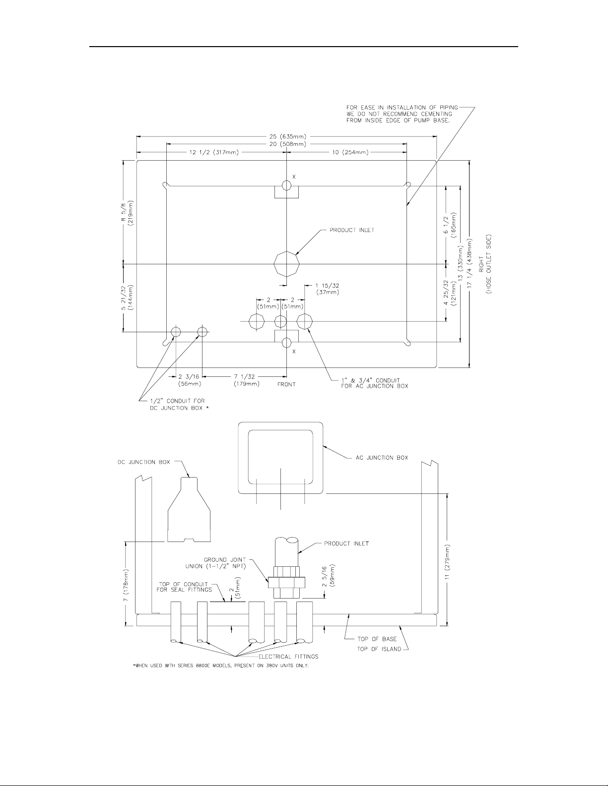
FOUNDATION
When construc ting the pump island for the dispensing equipment , be sure to extend the island
excavation beyond t he depth of the frost line. Leave open an area from the inside edge of the
unit's base as shown on t he specific base layout. Unles s required by local regulations, do not
cement the pipes and conduit s int o the island. T he open area within the base will provide access
for future servicing of the fittings, check valve and conduit assemblies. Fill in the boxed-in
section with dry sand to keep condensation in the pump housing to a minimum and to help
prevent fogging of the totalizer window.
Secure the pump/remote dispenser to the island using anchor bolts through the two mounting
holes, which are 13 inches (330mm) apart and are indicated on each base layout by an X. If the
dispensing unit is not sec urely fastened to t he island, supply line leaks at unions and pipe joints
may occur. Use one of two types of bolts to anchor the pump to t he island. Use two (2) 1/ 2" x 5"
(13mm x 125mm) machine bolts imbedded in the concrete, or, to meet minimum UL and API
requirements for universal interchangability of pumps, use two 1/ 2" x 3 1/2" (13mm x 90mm) lag
screws with 2" (51mm) expansion shields.
SUCTION PUMP
The pump and the t ank should be loc ated c lose to eac h other wit h as f ew changes in direc tion of
the supply line, as poss ible. This reduces the poss ibility of vaporization (gasoline only), attains
the highest possible flow rate, and results in a lower installation cos t. Avoid long supply lines and
excessive vert ical lifts. T he dynamic lift f or this unit is rat ed at 12 feet (3.66m ) for gasoline and
13 feet (3.96m) for diesel and can vary according to conditions of the installation and fuel
temperature.
If a pump is to be us ed with an above-ground t ank, a press ure regulator valv e is required on the
suction side of the pump; consult your GASBOY representat ive for details. The t ank should be
free of water and dir t. It is r ec om m ended that the tank be pres sure tested to v er ify it is tight.
NOTE: The out let f itt ing at t he top of the f loat c hamber should be c onnected t o drain back to t he
storage tank. The pipe size for the ret urn line to the storage tank should be at least 3/8"
(9.525mm).
REMOTE DISPENSER
0279 2-3
Page 14

GASBOY Series 9100A
Locate the rem ote dispens er and t ank wit h submers ible pump as cl ose to eac h other as possible
to attain minimum possible pressure drop and t he highest possible flow rate, consistent with the
pump capacity. Cons ult the submersible pum p manufacturer's recommendations f or pipe sizing
and installation instructions pertaining t o the model of submersible pump being installed.
2-4 03/07/03
Page 15

Installation
A Listed emergency shut-of f v alve (O PW 10RUS or equal) must be installed under each rem ote
dispenser with the shear groove at the same level as the top of the concrete island +
1/2"
(12.7mm). The shutof f valve should be rigidly supported to insure proper shearing and closure of
the valve in the event the r emote dis penser is dis lodged. Ac cording t o the t ype of s hear valv e, a
different supply nipple may be required.
After a shear valve has operat ed on an emergency basis from f ire or mechanical shock, or
if it do es not op erate correctly wh en inspect ed, repairs mu st be made befo re puttin g the
remote disp enser into service.
It is required by t he F lammable and Combus tible Liquids Code t hat a leak detect or be installed in
the system to prevent underground leaks f rom going unnoticed.
NOZZLE, HOSE, AND ACCESSORIES
This unit is normally equipped for use with a UL-Listed interchangeable service station type
nozzle. Units equipped wit h suffix N are equipped for use with a UL-Listed Richards Mark XIIL
nozzle. Only UL-Listed hose assemblies and accessories are to be used with this device. A
Listed breakaway connector must be inst alled on all hos e as s em blies .
SUPPLY LINE
Use new galvanized or fiberglass (see note) pipe, 1 1/2" (38.1mm) minimum diameter.
NOTE: Fiberglass pipe is to be installed according to manufacturer's specifications and
requirements.
Be sure both the pipe and the tank are clean. Foreign matter entering the pump can cause
extensive dam age. Obst ructions in the supply line can cr eate pump problems and reduced flow
rate.
Make sure all pipe threads are properly cut and the ins ide reamed to remove burrs. Use Listed
gasoline-resistant compound on all joints of gasoline handling piping. Sealing compound must
also be resistant to Gasohol (Ethanol and Methanol). Do not use Teflon Pipe Sealing Tape.
Use gasoline-resistant pipe compound on male threads only; pipe compound used on female
threads can be squeezed int o the supply line where it can enter t he product stream and become
lodged in the pump or meter . I nstall s wing joints under the pump and at the t ank t o avoid breaks
in the supply line from settling or fros t heave.
To avoid product deliver y problems on suction pumps, be sure there are no traps in the supply
line. Supply lines, for both suction pumps and submersible pumps, should go straight down
beneath the pump t o a point 18 inches (45. 7cm) below t he ground level and pit ch at a rate of 1/8
inch (3.18mm) per foot (.305m) from t here down to the storage tank. The supply line should be
as short and direct as poss ible with swing joint s at all turns . Suppor t t he horizont al run of pipe at
10-foot interv als to maintain pitch and prev ent traps. Do not us e wood as pipe s uppor ts.
New EPA regulations require that only one check valve be used per supply line and located
directly below, and as c lose as pract ical to the suc tion pump. Do not use spring-loaded or union
check valves since these will unnecessarily r educ e the flow rate and cont r ibute to the reduction of
atmospheric pres s ur e nec es s ar y to keep gasoline in a liquid state.
Upon completion of installation, all liquid-carrying lines must be checked for leaks.
0279 2-5
Page 16

GASBOY Series 9100A
SINGLE PUMP/REMOTE DISPENSER DIMENSIONS
2-6 03/07/03
Page 17

Installation
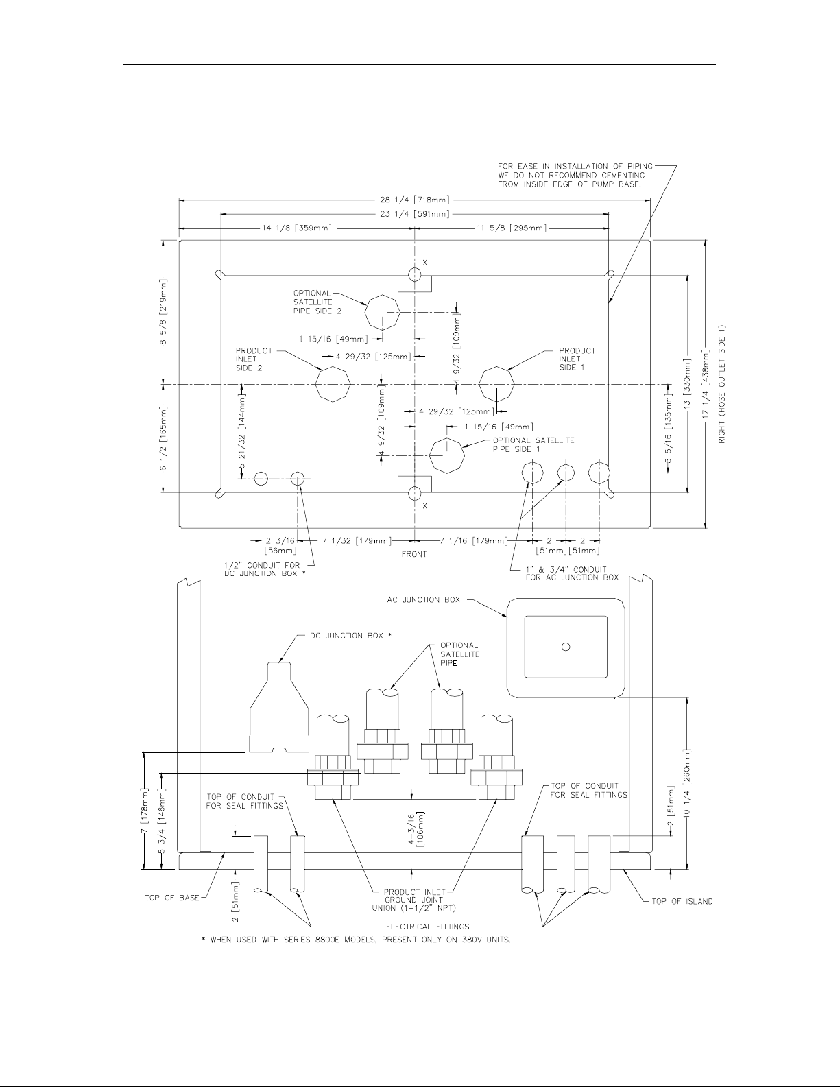
TWIN PUMP/REMOTE DISPENSER DIMENSIONS
0279 2-7
Page 18

GASBOY Series 9100A
9140A REMOTE DISPENSER DIMENSIONS
2-8 03/07/03
Page 19
Installation
011865 BASE LAYOUT
Model: 9153AHC
0279 2-9
Page 20

GASBOY Series 9100A
011873 BASE LAYOUT
Model: 9152ATW1
2-10 03/07/03
Page 21

Installation
011887 BASE LAYOUT
Models: 9152ATW2, 9153ATW2
0279 2-11
Page 22

GASBOY Series 9100A
011888 BASE LAYOUT
Models: 9153ATW1M
2-12 03/07/03
Page 23

Installation
011892 BASE LAYOUT
Models: 9152A, 9153A
0279 2-13
Page 24
GASBOY Series 9100A
011894 BASE LAYOUT
Models: 9152AXTW2, 9153AXTW2
2-14 03/07/03
Page 25

Installation
011898 BASE LAYOUT
Models: 9140AX
0279 2-15
Page 26

GASBOY Series 9100A
011971 BASE LAYOUT
Models: 9152AX, 9153AX
2-16 03/07/03
Page 27

Installation
011972 BASE LAYOUT
Models: 9152AXTW1, 9153AXTW1
0279 2-17
Page 28
GASBOY Series 9100A
011981 BASE LAYOUT
Models: 9140A
2-18 03/07/03
Page 29

Section 3
CONTROL LINES
PURPOSE
This section is provided to familiarize the installer with the control inputs and outputs that are
available for the Series 9100A dispensing unit. It is recommended the installer read these
descriptions to obt ain a bet ter wor king knowledge of the unit in order t o guide him in planning the
site wiring. Refer enc e S ection 4 for specif ic wir ing diagr am s and ins tallation notes.
The Series 9100A may be provided f or use with 230 VAC power for international applic ations.
The operating voltage for control lines t o these units is shown in parent hes es as ( 230 V A C Int'l).
If connecting the 9100A to a GASBOY fuel management system, refer to the Series 1000
Installation Manual, C08922; the CFN Site Controller I Installation Manual, C01917; the Site
Controller II Installation Manual, C01918; or the CFN Islander Installation Manual, C35520; for
installation inform ation.
GROUNDING
To ensure proper operation of the equipment and provide the necessary saf ety factors, a good
ground line must be provided. A ground wire (preferably green) must be connected between the
unit's AC junction box ground lug and the main electrical service panel. One (1) earth ground
connection is required per unit. The ground rod is to be a solid, corr osion-resistant conductor
and must be installed at the main electrical panel in acc or danc e with the National Electr ic al Code.
It should be properly t ied into the gr ound bus strip of the panel. We recomm end the neutral and
ground bus strips be bonded together (unless prohibit ed by loc al c odes ) .
RESET MOTOR FEED
The reset motor feed is a 115 VAC (230 VAC Int'l) input which is supplied through the pump
handle switch to act ivate the reset motor. W ithout power supplied to this line, t he unit will not
reset when the pump handle is turned on. T wo feed lines are provided for twins. This feed is
also connected to t he input of one of the int ernal switches of t he electric reset . When the reset
finishes its cycle, the 115 VAC (230 VAC Int 'l) input to the switch will be passed through as an
output caus ing the solenoid valve ( optional in some models) to open and the reset complete line
to indicate 115 VAC (230 V A C Int'l).
PUMP MOTOR FEED
The pump motor feed is a 115 VAC ( 230 VAC Int'l) input which is supplied to the input side of
one of the internal switches of the electric reset. When the reset finishes its cycle, t he 115 VAC
(230 VAC Int'l) input t o the switch is passed through as an output causing the pum p motor to
receive power and begin running. W ithout power t o this line, t he unit would reset , but be unable
to fuel. Two feed lines are pr ovided in twins which contain t wo motors. T he gauge of this wire
(and its neutral wire) should be determined according to the size of the motor, the voltage at
which the motor will be powered (115V AC or 230VAC), and the distance f rom the break er panel
03/07/03 3-1
Page 30

GASBOY Series 9100A
to the pump. I t is pos sible t o combine t he pump mot or feeds for t wins and supply them from one
breaker; however, the gauge of the wire needs to be adjusted to handle the load of two motors.
3-2 03/07/03
Page 31

Control Lines
RETURN
The return is t he AC current return line back t o the breaker panel f or all attac hed devices (pump
motor, reset motor , solenoid valv es). The gauge of this wir e should be equal to t hat of t he pump
motor feed (suction pumps) or submersible feed (remote dispensers). This wire is commonly
referred to as the neutral wire.
SUBMERSIBLE FEED, SUBMERSIBLE DRIVE
The submers ible feed is a 115 VAC (230 VAC I nt'l) input which is supplied to t he input side of
one of the internal switches of the electric reset. When the reset finishes its cycle, t he 115 VAC
(230 VAC Int'l) input to the swit ch is passed through as an out put (submersible driv e) to drive a
starter relay or to directly drive a submersible motor up to 1 HP at 115VAC/230VAC. Any
submersible motor ex c eeding this limitation must use a starter r elay .
RESET COMPLETE (SWITCH DETECT)/SLOW FLOW
The reset complete is a 115 VA C (230 VAC Int'l) output which is used to indicate the reset is
complete and the dispens ing unit is ready t o dispense pr oduct. Two lines are provided f or t wins.
This line should only be us ed when monitoring of the dispensing unit is desir ed as when used
with a Fuel Management System. This line must be capped when not in use. This line is
connected to the s low flow stage of the s olenoid in the pump.
FAST FLOW
This is a 115 VAC (230 VA C Int'l) input which controls t he fast flow valve of the pump/rem ote
dispenser (when a slow/f ast flow valve is available) I f slow/fast flow c ontrol is not desired, this
line should be tied to the res et complete/ slow flow line. The line should be switc hed through the
fuel management system and only be on when the pump/remote dispenser is authorized and t he
pump/remote dispenser should be in fast flow mode. This line will be switched on when the
pump/remote dispenser is in the manual mode.
LIGHT FEED
The light feed is a 115 VA C (230 VAC Int'l) input r equired to power the fluorescent lights. In a
site configurat ion using mult iple remot e dispenser s (or pum ps), the power for t he lights of up t o 8
units can be supplied by 1 breaker. If separate cont rol of the light s is not desired, the light f eed
for each dispensing unit may be taken from its Reset Motor Feed.
LIGHT NEUTRAL
The light neutral is a return line for AC current from the lights to the breaker panel. When a
separate breaker is not used t o cont rol the light s, the light neutral is attached to the neutral which
is connected to t he r eset motor.
PHASE 2 FEED
The phase 2 feed is a hot f eed which is the opposite phase of t he pump motor feed. This line
and the pump motor f eed are used for domestic 230V A C m otor applications.
PULSER
6304 3-3
Page 32

GASBOY Series 9100A
The pulser supplies a DC output which is provided to indicate the quantity dispensed. Pulsers
are optional and are only used when monitoring of the dispensing unit operation is desired as
when used with a fuel management system.
3-4 03/07/03
Page 33

Section 4
WIRING
☎ Customers and installers having any questions pertaining to the installation should
contact their GASBOY distribu t or.
WIRING PRECAUTIONS
The quality of the electrical inst allation is a major factor in maintaining proper safety levels and
providing trouble-free operat ion of your GASBOY pump/remote dispenser. To assure a qualit y
installation, f ollow these rules:
1. All wiring must be installed to conform with all building/fire codes, all Federal, State, and
Local codes, National Electrical Code, (NFPA 70), NFPA 30, and Automotive and Marine
Service Station Code (NFPA 30A) codes and regulations. Canadian users must also
comply with the Canadian Elec trical Code.
2. Use only threaded, rigid, metal conduit.
3. Use only UL-labeled insulated gasoline- and oil-resistant stranded copper wiring of the
proper size.
4. Wir e connections s hould be tightly spliced and secured with a wir e nut; close off t he open
end of the wire nut wit h elec trical tape.
5. The line to the motor should be on a separate circuit and installed on a 20 to 30 AMP
breaker depending on the motor size and/or the voltage setting.
6. Install an emergency power cutoff. In addition to circ uit breaker requir ements of NFPA 70
and NFPA 30A, a single control which simultaneously removes AC power from all site
dispensing equipment is recommended. This control must be readily accessible, clearly
labeled, and in accordance with all loc al c odes.
In a fuel management system application, the EMERGE NCY STOP and STO P keys on the
console and/or the optional EMERGENCY STOP but ton on the Island Card Reader do not
remove AC power fr om equipm ent and under certain conditions , will not stop product flow.
In order to provide t he highest level of safety to you, your employees, and customers, we
recommend that all employees be trained as to the location and procedure for turning off
power to the entire system.
WARNING:
To reduce the risk of elec trical shock when s er v ic ing, turn off all power to
the pump/remot e dispenser. In submersible pump applicat ions, turn off
power to the s ubmersible pump and any other remote dispensers which
use that submersible pump. AC power can feed back into a shut-off
dispenser when dispensers share a common submersible pump or
starter relay.
7. Have the pump/remote dispenser installed by a competent ins taller/electrician.
03/07/03 4-1
Page 34

GASBOY Series 9100A
GROUNDING
To ensure proper operat ion of the equipment and prov ide the necessary saf ety factors , this unit
must be grounded. A ground wire (prefer ably green) must be connect ed between the unit's A C
junction box ground lug and the main elec trical service panel. One (1) earth ground connec tion is
required per unit. The ground rod is to be a solid, corrosion-resistant conductor and must be
installed at the main electrical panel in ac c or danc e with the National Electr ic al Code. It should be
properly tied into the gr ound bus strip of t he panel. We rec ommend the neutr al and ground bus
strips be bonded toget her (unless prohibited by local c odes ) .
CIRCUIT BREAKERS
Power to the unit s hould be supplied from a dedicated breaker. No other equipment should be
powered from this breaker. Remote dispensers may be grouped together on a single breaker
when the submersible pump has its own breaker. It is recommended that no more than two
remote dispensers be powered from one breaker to maintain isolated control with the circuit
breaker panel in case of pr oblems. Units directly driving pumps (suction or submersible) should
be supplied power from a separ ate breaker. A t ag on the motor identifies the maximum current
draw of the motor. If t wo ( 2) pum ps are supplied from one breaker, that breaker m us t be capable
of handling the load of both m otors. I n cases where multiple remot e dispensers supply power to
a single subm ersible pump, all breakers cont rolling the remote dispenser mus t be on the same
phase of power. Failure to do this will damage the equipment. Provisions must be made to
break both legs of any A C c ir c uit.
THE PUMP MOT OR
Pumps are shipped from the factory with mot ors wired according to the spec ifications given on
the order as to k ind of current, f r equenc y and voltage.
Very often on installation, it becomes necessary to change the original setting to suit the AC
power source. To do t his, locat e the motor change-over plate, typically loc ated on the shaf t end
of the mot or, and r emove t he scr ew which secur es it in plac e. Slide t he plate s o that the desir ed
voltage, as mark ed on the plat e, lines up with t he screw hole. Reinsert the screw and secure the
plate in place.
Many motor failur es result from improper setting of the motor change-over plate. If set for 115
VAC and a 230 VAC feed is used, the motor will burn out after running only a short time. If set
for 230 VAC and a 115 V AC feed is used, the mot or will run v ery slowly and the st art ing field will
soon burn out.
MOTOR AMP RATINGS
The following chart shows the maximum running amperage that can be expected for each
pump motor, unless noted otherwise:
Models 115v/60hz units 230v/60hz units 230v/50hz units
9152A, 9152ATW2 7.8 3.9 3.5
9152ATW1, 9153A, 9153ATW2,
9153ATW1M
9153AHC, 9140A (2 motors combined) Not available 11 (See NOTES) 13 (See NOTES)
NOTES:
1. These numbers do not account for the higher load upon startup, nor up to one additional amp
associated with other electrical components (lights, solenoid valves, etc.).
11 5.5 6.5
4-2 03/07/03
Page 35

Wiring
2. The 9152ATW2, 9153ATW2, and 9153ATW1M have one pump motor per side.
3. The 9153AHC and the 9140A models should use no less than a 20-amp breaker to account for the
high current upon startup.
03/07/03 4-3
Page 36

GASBOY Series 9100A
WIRE SIZE
The table below shows the r equired AC wire size for suct ion and submersible pumps based on
the HP rating of t he pump motor and the distance from t he circuit breaker to t he pump/remote
dispenser for bot h 115 and 230 volt units. Us e this t able as a guide f or select ing the pr oper siz e
wire for the Pump Feed, Phase 2 Feed, and Return.
The table also applies to the Disp Feed, and Subm Drive of a dispenser when the submersible
pump is directly driv en via t he dispenser c ontrol c ircuit ry. A st art er relay must be used; however,
when the s ubmersi ble pum p m otor is gr eater t han 1 HP at 115 VAC or 2 HP at 230 V AC. W hen
using a starter relay for the pump motor, the contr ol lines to the dispenser may be 12 A WG.
The AC wire size of the control lines of a pump (Res et Motor Feed, Pump Motor Feed, Neutral
Feed, Phase 2 Feed) or remote dispenser (Reset Motor Feed, Submers ible Feed, Submersible
Drive, Neutral Feed) should be 12 AWG unless you are using a starter relay. A starter relay
must be used whenever the submersible motor is gr eater than 1 HP at 115/ 230 V A C.
If mult iple units are powered f rom t he same breaker t hrough the same wir es, you must increase
the gauge of the wires t o handle the added load ac cording t o the distance from the breaker panel
and the HP rating (if applicable).
The AC wire size for the Light Feed and Light Neutral, when the light s are wired from a single
dedicated breaker, should be 14 AWG for distances up to 300 feet (91.4m) or 12 AWG for
distances over 300 feet (91.4m).
The AC wire size for the Res et Complet e (Swit ch Det ect) and Fast Flow lines should be 14 AWG
(when they are used).
The DC wire size for t he Pulser lines mus t be 18 AW G ( when they are used). Shielded cable as
described in the Pulser section allows pulser lines to be run with the AC wires.
Wire Size
4-4 03/07/03
Page 37

Wiring
CONDUIT
All wiring to the GASBOY Series 9100A dispensing unit must be installed in threaded, rigid, met al
conduit. PVC is not acceptable. When the Series 9100A dispensing unit is used with a
GASBOY fuel management system, it is recommended that AC power wires be installed in a
separate conduit from the DC pulser; they should not run in any sort of common conduit or
trough. However, if AC and DC power wires share conduit , pulser wiring m ust use the c able as
specified in the Pulsers section.Wiring between a Fuel Point Reader (FPR) and its pre-amp
junction box is intrinsically safe and must be run in a conduit with only other intrinsically safe
wiring. It cannot be run in conduit with A C, DC, RS-485, or pulser wiring, r egardless of the c able
type used. See t he Fuel Point Reader Installation and Retrofit Manual, C35628 for details.
When using a fuel management system other than a GASBO Y system, see the manufacturer's
installation manual for s pecific conduit requirem ents.
All wiring and conduit runs mus t also conform with t he National Electrical Code (NFPA 70) and
the Autom otive and Marine Service St ation Code (NFP A 30A). All wir ing and conduit runs mus t
conform to local c odes . Canadian users must als o c om ply with the Canadian Electrical Code.
Use the charts below as a guideline to determine the proper conduit sizes for the GASBOY
Series 9100A dispensing unit. When planning the orientation of the wiring runs, follow the
applicable GASBOY wiring diagram and consider the layout of the component s at t he site. Long
runs or a large number of bends m ay r equir e y ou to increase conduit siz e ov er what is listed.
To determ ine conduit size needed, us e the THHN/T HWN Wire A reas table (lef t) to f ind the area
for each wire gauge. Add up all wire areas. Us e the Areas of Trade S i z e Conduit Table (right) t o
select the smalles t number in the 25% f ill area (bas ed on NEC 501-1) t hat c omes clos est wit hout
exceeding the total wir e ar ea.
03/07/03 4-5
Page 38

GASBOY Series 9100A
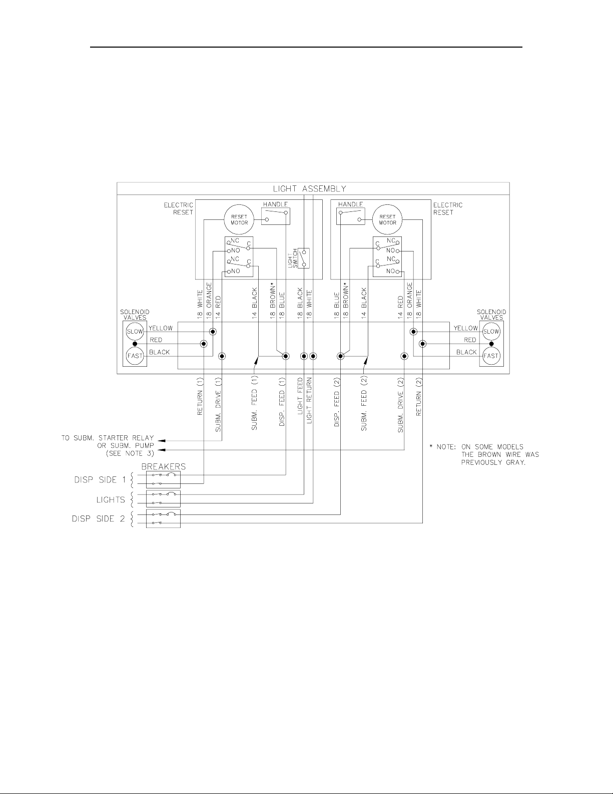
WIRING DIAGRAMS
The following pages contain wiring notes and wiring diagrams. Consult the appropriate wiring
diagram for your pum p/remote dispenser model and follow all notes.
Wiring diagram s are presented in numerical or der. Wiring diagram 024214 has two diagrams:
one for simultaneous operation of master and sat ellite and one for non-simultaneous operation.
Be sure to use the c orrect one for your applic ation.
NOTES:
1. All wiring and conduit runs mus t conform wit h all building/fire codes, all Federal, State, and
Local codes, National Electrical Code, (NFPA 70), NFPA 30, and Automotive and Marine
Service Stat ion Code ( N FPA 30A) codes and regulat ions .
2. When wiring pumps, f or 115 VAC applications, motors can be wired as 230 VAC to reduce
current draw. See breakaway view of Optional 230 VAC Motor. The selector switch
should be set t o the 230 V position. All other wiring s hould remain the sam e except for the
addition of the L2 (requires 230 VAC breaker for c ontrol).
3. When wir ing remot e dispenser s, s ubmersible star ter relays are always recomm ended when
a submersible pump is used; however, the control circuit is capable of directly driving a
submersible pum p up t o 1 HP at 115/ 230 VAC. Any pump over these r atings will require a
submersible star ter relay.
4. If using a satellit e for fueling, s ee Weights and Measures Handbook 44 to determine which
mode of satellite oper ation is r elevant for y our applicat ion. I n many cases, the satellite must
be wired so it cannot dispense pr oduct while the mas ter r emote dis penser is dis pensing and
vice versa. Use the correct wiring diagr am ac c or ding to your application.
5. If combining a remote dispenser with a fuel management system, the maximum HP
limitation for directly driving a remote dispenser without the use of an additional relay or
submersible star ter must be the lower of the two components.
6. Use the wire size chart listed on page 4-3 when determining the wire size for the control
wiring.
4-6 03/07/03
Page 39

Wiring
024212 WIRING DIAGRAM
Models: 9152AX
9153AX
9140AX
03/07/03 4-7
Page 40
GASBOY Series 9100A
024213 WIRING DIAGRAM
Models: 9152AXTW1
9152AXTW2
9153AXTW1
9153AXTW2
4-8 03/07/03
Page 41

Wiring
024214 WIRING DIAGRAM
Models: Satellite Island-Oriented Nozzle (side), 215A/9152AX, 9153AX
Satellite Island-Oriented Nozzle (side), 216A/9153AX, 9140AX
03/07/03 4-9
Page 42

GASBOY Series 9100A
024222 WIRING DIAGRAM
Models: 9152ATW2
9153ATW2
9153ATW1M
4-10 03/07/03
Page 43

Wiring
03/07/03 4-11
Page 44

GASBOY Series 9100A
024223 WIRING DIAGRAM
Models: 9152ATW1
4-12 03/07/03
Page 45

Wiring
024224 WIRING DIAGRAM
Models: 9152A
9153A
03/07/03 4-13
Page 46

GASBOY Series 9100A
024225 WIRING DIAGRAM
Models: 9153AHC
9140A
4-14 03/07/03
Page 47

Wiring
024320 WIRING DIAGRAM
Models: Satellite Lane-Oriented Nozzle, Front Load 215AZ/9152AX, 9153AX
Satellite Lane-Oriented Nozzle, Front Load 216AZ/9153AX, 9140AX
03/07/03 4-15
Page 48

Page 49

Section 5
PULSERS
GENERAL
A pulser is an optional device which is used when external monitoring of the dispensing unit
operation is desired. T he pulser transmits one electr ical signal (pulse) for each predetermined
amount of fuel dispensed. The signal is received by the external monitor (fuel management
system) which keeps a running total of the quantity of fuel being dispensed during each
transaction.
All Series 9100A pulsers ar e operated with DC voltages . These pulsers include the reed pulser
which outputs 10 pulses per unit of measure and the electronic pulsers which are av ailable at 100
pulses per unit of measure. The pulser type should be selected according to the monitoring
equipment, the application, and the regulations that must be met .
All Series 9100A pulsers are driven by shafts or gears from the non-computer register. The
EXTQTY shaft is the pulser drive most commonly used to meet requested puls er applications.
This shaft is for quantity and does not turn during reset . The register offers another pulse drive
which is seldom used by GASBOY. It is the RHQTY gear which is attached to the right hand
quantity wheel which r esets to the sam e position at t he beginning of each trans action during the
reset process.
WIRING
When installed in a separat e DC conduit, 18 AW G wires ar e required for installation. Although it
is recommended that DC pulser wires be run in a conduit separate from AC wires, they can be
combined in the same conduit with AC wires providing UL-Listed cable with the following
specifications is us ed:
Conductor: 18 AWG str anded wire. Number of conductors to be determined by pulser
requirements.
Shield: Foil-wrapped 100% coverage and/or tinned copper braid 90% cover age
Drain Wire: Stranded, tinned c opper, 20 AWG or lar ger /or braided shield
Voltage Rating: Maxi m um oper ating voltage of 600V
Environmental: Gas- and oil-resistant; suitable for wet or dry locations.
GASBOY can supply Belden 1063A (P/N C09655) which is a UL-Listed, 4-conductor cable t hat
meets the requirements listed above. NOTE: Belden 1063A is UL- Lis ted but not CSA list ed.
03/07/03 5-1
Page 50

GASBOY Series 9100A
REED PULSERS
NOTE: See Pulser, Wiring section for proper select ion of pulser wires.
5-2 03/07/03
Page 51

Pulsers
ELECTRONIC PULSERS
NOTE: See Pulser, Wiring section for proper select ion of pulser wires.
03/07/03 5-3
Page 52

Page 53

Section 6
START-UP
COMPLETION CHECK LIST
The information below should be reviewed to help verify the proper installation of the Series
9100A dispensing unit. If t he inst allati on do es not meet criteria l isted, correct th e probl em
before the start-up is performed.
1. The unit must be properly secur ed to the island.
2. All plumbing m ust be complete and tight. All liq uid-carryi ng lin es must be checked for
leaks.
3. When DC pulsers are used in the pump for connecting to GASBOY fuel management
systems, AC and DC wires should not share any conduit s, junct ion boxes, or troughs unless
the restric tions outlined in the Pulsers, Wiring section are m et.
4. All conduit work must be complete. All junction box covers must be secured. Conduits
should not be sealed until the wir ing is verified through proper oper ation.
5. The unit must be properly grounded.
6. Before any testing begins, remove any water in the tank through a fill opening, using a
suitable pump. Do not use the G ASBOY pump or remote dispenser and submersible pump
to remove water. Serious damage may occ ur .
7. A suff icient volume of fuel must be put in the tank to insure that the liquid level is above the
bottom of the s uction pipe ( suct ion pumps) or is high enough t o allow the subm ersible pum p
to operate eff ic i ently (remote dispenser s ) .
START-UP
After succ essfully verif ying the installation against the completion check list, the unit is ready for
start-up. Follow the procedure listed below to perf orm an orderly start-up of the Series 9100A
dispensing unit.
1. Turn on the circuit breaker( s ) for the various control lines to the unit.
2. Remove the nozzle for Side 1 from its holder and turn on the pump handle. Verify that the
non-computer register goes through its reset sequence, which consist s of the total volum e
wheels resetting t o all z eroes.
3. Dispense fuel. If the unit contains a slow/fast flow valve, verify that it opens. Check all
plumbing for leaks at this time.
4. Turn the pump handle off. Open the nozzle. No f uel s hould be dis pens ed.
03/07/03 6-1
Page 54

GASBOY Series 9100A
5. Dispensing units equipped wit h an optional light assembly, should have the light assembly
tested to verify proper operation of the fluorescent light. The light control circuit may be
wired from the pum p breaker (reset motor f eed) or from its own separat e breaker. In either
case, t urn on the proper br eaker and verify that the fluor escent light will light. If t he light
does not come on, the light swit ch in the electr ic reset unit of the dispens ing unit may be in
the "off" position (if the unit is equipped with the opt ional light switch). In twin dispensing
units the reset unit on the right side of the twin (the side wit h the serial tag) will be the one
which controls the light. To change t he switch pos ition, locat e the small plast ic access cap
which is located on t he side of the pump, slightly below and left of the pump handle. P ull
this cap out and insert a pencil or screwdriver into t his hole and press firmly inward until a
"click" sound is hear d, indicating a change in t he switch posit ion. Pressing the switch again
will change t he switch to its original position. When the switch selec tion is complete, replac e
the plastic cap by pr es sing it firmly int o its initial position.
6. Repeat Steps 2, 3, and 4 for Side 2 (if applicable).
7. The dispensing unit should go through all standar d c alibr ation procedures. (See page 6- 3).
POST START-UP TESTS
Voltage
The incoming volt age to t he pump and rem ote dispens er should be chec ked and any reading not
within 10% of rat ed voltage should be correct ed before test ing is continued. When dealing wit h
suction pumps it is good pr actic e to t ake volt age readings while t he suct ion pump is operat ing on
bypass and also while making a delivery . Any voltage drop in excess of 10% during eit her of
these operating st ates s hould be consider ed a low voltage condition. Corrective action should be
taken to insure an adequat e power supply to the pump.
Tightness
After determining that t he pump is operating satisfactorily and the system is f ully primed, check
the pump and piping to make sure that all connections are tight. In the case of a remote
dispenser you should follow the submersible pump manufacturer's instructions to check the
system for tightness. W e recommend that the tank and all piping not be covered until this test
has been completed.
Belts (Suction Pumps Only)
Since belts do stretch slightly during the first few minutes of operation, check the belt tension
after completing the operational test; a properly tightened belt will permit twisting the belt 180
degrees midway between t he m otor and pump pulleys.
On the 9152A, 9153A, 9153AHC, 9152AT W2, and 9153AT W2 models, the belt can be tightened
by loosening the hex nut which holds the idler pulley and sliding t he pulley to eit her side to obtain
the correct belt tension of 6-3/4 lbs., +
remember to retighten the hex nut.
3/4 (30N, +3.3N). When the adjustment is complete,
6-2 03/07/03
Page 55

Start-Up
On the 9152AT W1 model, t he belt can be t ightened by loosening the c ap screw which holds t he
idler arm and sliding the arm to obtain the correct belt tension of 6-3/4 lbs. +
When the adjustment is complete, r em em ber to retighten the cap screw.
3/4 (30N, +3.3N).
03/07/03 6-3
Page 56

GASBOY Series 9100A
Calibration
All GASBOY pumps and remote dispensers are adjusted for accurate measure at the factory.
However, since the c onditions of t he installation c an affect pump accuracy, it is the responsibility
of the installer to check the pump for accuracy and make any needed adjustments. Where
required, it is t he owner's responsibility to r eport this device to the local Weights and Measures
officials for their inspection befor e the unit is put into ser v ic e.
The adjustment of measurement is
accomplished by breaking the seal wire and
removing the Seal Pin. This will permit the Index
Disc, to be turned either counterclockwise (-),
decreasing the measurement, or clockwise (+),
increasing the measurement. A variation of
approximately one cubic inc h in measurement is
obtained by turning the Index Disc five holes.
After measurement has been proper ly adjusted,
the Seal Pin and seal wire should be r eplac ed.
POWER RESET EXTERNAL ADJ USTMENT
If the pump or r emote dispenser fails to reset or shut off properly, t he power reset may need t o
be adjusted. To adjust:
1. Loosen the lock nut on adjus ting screw and back screw out unti it stops .
2. Move reset lever to ON position.
3. Turn adjustment screw in until reset m otor starts . Advance adjustment s c r ew an additional
½ to ¾ turn and t ighten lock nut.
4. Turn reset lev er to OFF, then back to ON to check proper operation. ( Res et coupling should
make one revolution and stop).
6-4 03/07/03
Page 57

Start-Up
03/07/03 6-5
Page 58

Page 59

Section 7
OPERATING SEQUENCE
PUMP
1. AC Power (115 VAC/230 VAC Int'l) must be provided to the pump motor feed and reset
motor feed (slow flow/reset motor feed if applicable).
2. When the pump handle is turned on, power (115 VAC/230 VAC Int'l) is supplied to the
electric r eset motor which imm ediately begins to reset the values on the pump non-com puter
register to zero. If pump fails to reset properly, see Section 6, Power Reset External
Adjustment.
3. When the reset is complete, power is removed from the reset motor and the internal
switches in the reset unit change to the normally open c ontacts. T his supplies power (115
VAC/230 VA C I nt' l) to t he pum p m otor and t o the r eset c omplete line. If this pump cont ains
a slow flow/fast flow or closure t y pe s olenoid v alv e, the valves will open at t his time.
4. The user begins to dispense product.
5. The register displays the total volume. If an optional pulser kit is attached, it will be
supplying pulses which may be recorded by an external monitoring system.
6. The fueling transact ion continues to run until t he user turns off the pum p handle. If pump
fails to shut off properly, s ee S ec tion 6, Power Reset E xternal Adjustment.
REMOTE DISPENSER
1. AC power (115 VAC/230 VAC Int'l) must be provided to the submersible feed and slow
flow/reset motor feed. If a submersible s tarter relay is used, A C power (115 or 230 VAC)
must be supplied to t he input contacts of the submersible st ar ter relay.
2. When the pump handle is turned on, power (115 VAC/230 VAC Int'l) is supplied to the
electric r eset motor which imm ediately begins to reset the values on the pump non-com puter
register to zero. If remote dispenser fails to reset properly, see Section 6, Power Reset
External Adjustment.
3. When the reset is complete, power is removed from the reset motor and the internal
switches in the reset unit change to the normally open c ontacts. T his supplies power (115
VAC/230 VAC Int 'l) t o the s ubmers ible star ter r elay, whic h in turn c loses and supplies power
to the subm ersible m otor. If a st arter relay is not used, the hot leg is supplied direc tly t o the
submersible motor . The remote dispens er will contain a slow flow/f ast flow or closur e type
solenoid valve, which will open at this t ime. At the same t ime the valve opens, the Reset
Complete line will go to 115 VAC/ 230 V A C Int'l.
4. The user begins to dispense product.
5. The register displays the total volume. If an optional pulser kit is attached, it will be
supplying pulses which may be recorded by an external monitoring system.
6. The fueling transac tion continues to r un until the user turns off the pump handle. If remote
dispenser fails to r es et properly, see Sec tion 6, Power Reset E xt ernal Adjust ment.
03/07/03 7-1
Page 60

Page 61

Section 8
PREVENTIVE MAINTENANCE
GENERAL
GASBOY pumps and remote dispensers are designed and constructed to give many years of
uninterrupted serv ice. In fact, hundreds of operators report years of trouble-fr ee operation with
absolutely no service expense. Yet, cert ain parts of a pump are bound to wear, and GASBOY
therefore recom mends a periodic inspection, at least twice a y ear, for such t hings as fuel leaks,
belt tension and condition, lubrication and strainer cleanlines s. If such a procedure is followed,
any small adjustment s that ar e necessary can be m ade before expensive, annoying breakdowns
occur. The result of this sound approach is continuous, profitable service from all of your
GASBOY equipment.
Procedures requiring disassembly of portions of the pump/remote dispenser must be
performed by qualified service personnel.
WARNING:
To reduce the risk of electrical shock when servicing, turn off all power to the
pump/remote dispenser. In submersible pump applicat ions turn off power t o the
submersible pum p and any other remote dispenser s which use t hat submer sible
pump. AC power can feed back into a shut-off remote dispenser when
dispensers share a com mon submersible pump or start er relay. Always turn off
all power to the remote dispenser and submerged pumps at the master panel
and close any impact v alve before perf orming any maintenance or service to the
remote dispenser, including the changing of any fuel filters or strainers. Also
block islands so no vehicles can pull up to the remote dispenser when the
dispenser is being wor k ed on.
HINTS FOR BETTER PUMP PERFORMANCE
Demand Compet ent Service
If your pump should s top or fail to operate properly, don't depend upon the repair service of a
general mechanic unless he is t horoughly familiar with the mec hanism. Experience shows that
the repair results will be much more satisfactory if you demand the service of a competent
representative of t he pump manufacturer. GASBOY has a distributor net work which services f uel
dispensing and management systems in every section of the country.
Use Authori z ed Parts
Should excessive wear, rust, or corrosion of parts cause inef ficient operation, it is always best to
replace them immediately; but if you want the best results and continuity of the Underwriters'
Label on your pump, be sure they are new authorized service parts supplied by G ASBO Y. Every
part of a pump or r emote dis penser is c arefully designed for a particular purpose. If it is replaced
by an incorrect or s ubs tandard substitut e, pump operation will be unsatis factory. Alway s us e new
gaskets or seals when servicing or rebuilding Gasboy equipm ent; do not re-use old ones .
03/07/03 8-1
Page 62

GASBOY Series 9100A
8-2 03/07/03
Page 63

Preventive Maintenance
Operate wi th Reasonable Care
Like any machine, the pum p or remote dispenser that is operated with reasonable care will last
longer and give better ser vice. Abuse should be avoided (such as dropping t he nozzle on the
ground, operating the unit with a dirty strainer , dragging the hose across the c oncrete island or
driveway, r unning the pump with t he nozzle closed for more than t wo minutes, etc. ). The time
and care given to your pum ps will be r eturned to you in the for m of dependable service.
PREVENTIVE MAINT ENANCE CHECK LIST
Keep Water Out
Water tends t o collect in under ground and above ground stor age tanks. This is due to moistureladen air being drawn into the s torage tank and condensing, or t o defective f ill openings that ar e
not properly protected with water tight covers . Storage tanks should be checked after every fill-up
for water and removed with a sump pump, to forestall serious damage to equipment. Water,
sediment, and other foreign matter that accumulates in the tank can be drawn up into the pump
or remote dispenser and c aus e failures.
Pump Lubrication
The pumping unit s hould be lubricated every six months or every 100, 000 gallons. Turn off AC
power. Apply a few drops of a light grade oil ( SAE 10) to the felt pad located on t he pump body
slightly above the shaft which connects to the pump pulley. Oil used should be suitable for
temperatures r anging from -40 F to 180 F .
All rotary pump models are packed with special "V" packings which can be easily replaced by
slipping the pump pulley off the shaft and removing the cap screws , retainer plate, and oil well
felt. Pull t he bearing from the pump shaft t o allow the new packing rings to be inserted. The
packing gland is spring-loaded to keep packing tight at all times. When old packing rings are
removed, be sure to replace them with a like number of new rings. It is important to fill the
stuffing box to prevent leaks.
Meter Lubrication
If t he m eter begins t o leak around t he drive s haft extending f rom t he top of the m eter unit, it may
be necessary to r eplace the Teflon seals. Turn of f the AC power. Remove the outer packing
gland plate and the upper bearing assem bly. When r eplacing the new seals (r eddish brown and
black) and the O-ring into the packing cavity of the meter cover, be careful not to damage them.
Hose Retrievers (If Applicab le)
The cable r eel assembly does not require lubricat ion but the cable should be checked periodic ally
and replaced when it appears worn or frayed.
0070 8-3
Page 64

GASBOY Series 9100A
Keep the Non-Computer Lubricated
Although the non-computers used in GASBO Y pumps are carefully adjusted and lubricated at t he
factory before shipment, they require (as do all mechanical parts) occasional cleaning and
lubrication when in service. The intervals at which this s hould be done vary with conditions of
operation, but under nor mal conditions it is necessary only twice a year, or after each 100,000
gallons delivered.
Turn off t he AC power t o the pum p. I t's easier t o clean and oil the non- comput er if you remove it
from the pump. Clean the non- comput er with c ompress ed air and wipe all accessible parts (such
as figure wheel drums) with a clean cloth. NOTE: Always wear protective safety goggles or
glasses when using com pressed air. Never use solvents , such as gasoline or kerosene, as this
will become t rapped in many of t he inaccessible bear ings and dissolve the new lubr icant when it
is applied.
A light, non-acid type oil (SAE 10) is recommended because this gives maximum protection in
varying tem per atures. The oil must also be acid-f r ee s o that it will not cause c or rosion of the cast
metal parts. A long handled, fine lettering brush is very convenient for applying the oil to all
bearings and s haft s and for applying light , nonf luid oil (grease wit h body sim ilar to t hat of chass is
lubricant) to t he bev el type gears.
Dial Face
Clean the dial face with a soft, clean, dam p c loth as often as necess ar y .
Cleaning the Strainer
Clean the s trainer immediately after the pump has been ins talled and tested, and again aft er a
few hundred gallons have been delivered. Thereafter, once every six mont hs, or as required.
The symptoms of a dirty or clogged strainer in a pump ar e slow delivery, noisy operation, and
pulsation. Before starting, close the 10RU safety shutoff valves under each pump you are
working on. Then follow these directions:
Pump: Turn off AC power to the pump. Locate t he Suction Strainer Cap on the plumbing
unit and unscrew it t o access and rem ove the str ainer. Use compr essed air to blow the dirt
out of the st r ainer.
Remote dispenser: Turn off AC power t o the dispenser, submersible pum p, and any other
dispensers which use that submersible pum p. Locate the Strainer Cap on the met er and
unscrew it to access and r em ov e the strainer. Use c om pr es s ed air to blow the dirt out of the
strainer.
NOTE: Always wear protectiv e s afety goggles or glasses when using compressed air .
Filter
8-4 03/07/03
Page 65

Preventive Maintenance
If the unit is equipped with a filter, check and change it at regular intervals. A dirt y filter in a pump
or remote dispenser will c ause a slower delivery rate. Ref er to the accessories section of your
parts manual to ensur e that you r eplace the filt er with one designed for your model. Always use
a drip pan directly below the f ilter when removing t he cartridge to prevent contamination of both
the soil and the electr ic al c omponents within the cabinet.
0070 8-5
Page 66

GASBOY Series 9100A
Cleaning By-pass and Regulatin g Valve Assembli es
By-pass and regulating valve assemblies should be removed only for cleaning and should be
checked if there is notable loss in system perf ormance. No adjustment is required. T o remove
the valves, turn off AC power to the unit. If the unit is in a remote dispenser, remove the
separator cover and clamp plate, allowing the by-pass valve assembly and regulating valve
assembly to be lifted from place.
Adjusti ng the Belt s - S uction Pumps Only
With t he proper care, belts will give exc eptionally good servic e. A loose belt not only cuts down
dispensing speed, due to slipping, but also results in exc essive wear. A properly tightened belt
will allow twisting the belt 180 degrees mi dway between t he mot or and the pum p pulleys. Befor e
adjusting any belt, turn off AC power to the pump/remot e dis pens er .
On the 9152A, 9153A, 9153AHC, 9152AT W2, and 9153AT W2 models, the belt can be tightened
by loosening the hex nut which holds the idler pulley and sliding t he pulley to eit her side to obtain
the correct belt tension of 6-3/4 lbs. +
3/4 (30N, +3.3N). When the adjustment is complete,
remember to retighten the hex nut.
On the 9152AT W1 model, t he belt can be t ightened by loosening the c ap screw which holds t he
idler arm and sliding the arm to obtain the correct belt tension of 6-3/4 lbs. +
3/4 (30N, +3.3N).
When the adjustment is complete, r em em ber to retighten the c ap s c r ew.
Preserve the Finish of Y our Pumps
Nearly all gasoline pumps are inst alled outdoors where t heir surfac es are subjected to the action
of the weather. As a result, it is necessary t o give the finish a reasonable am ount of care if an
attractiv e appearance is to be maintained.
The finish on GASBOY pump housings is a high-heat baked synthetic enamel, similar to that
used on automobiles. The life of this finish can be lengthened several years if, at regular
intervals, t he painted surfaces are thoroughly cleaned wit h a high grade automobile polish and
then protec ted with a coat of pas te wax. Do not use abrasiv e c leaner s or polish. Do not use high
pressure spraying equipm ent.
In order to retain the unmarked finish on stainless steel, occasional cleaning is required. In
corrosive atm ospheres, such as coas tal areas, a more frequent cleaning schedule is necessary.
Under ordinary conditions , washing with detergent or soap and water, followed by a clean water
rinse, is suff icient. If har d water is used, the surfac e should be wiped dry with a s oft clean clot h
to prevent the formation of wat er spots. Marks or spots , such as grease, oily fingerprint s and
smudges which resist soap and detergents, will hav e to be removed with a stronger cleaner. (DO
NOT use ordinary s teel wool as iron particles may adher e to the surface and cause corrosion.)
Care should be taken in choosing a cl eaner because any cleaning compounds or powders which
contain abrasives can s cratch a mill-rolled finish. Care must be exercised in their use to run in
the direction of t he polishing lines in the st eel, never ac ross them. After cleaning, an application
of paste wax is rec ommended to protect the surface and prolong the interval between cleaning.
8-6 03/07/03
Page 67

Preventive Maintenance
0070 8-7
Page 68

GASBOY Series 9100A
GW01 - 6/04/02 Rev. 1
WARRANTY
General Statements:
Gasboy International LLC. warrants all new equipment manufactured by Gasboy against defective material and/or workmanship, for the warra nty
period specified below, when the equipment is installed in accordance with specifications prepared by Gasboy.
This warranty does not cover damage caused by accident, abuse, Acts of God, lack of surveillance of automatic recording systems, negligen ce,
mis-application, faulty installation, improper or unauthorized mainte nance, installation or use in violation of product manuals, instructions, or wa rnings.
Under no circumstance shall Gasboy be liable for any indirect, special, or consequential da mages, losses, or ex penses to include, but not limited
to, loss of product, loss of profits, litigation fees, or the use, or inability to use, ou r product for any for any purpose whatsoever.
Parts Only - During the warra nty period , Gasboy will, at its option, repair or replace defective parts returned transportation prepaid to its factory.
On-Site Labor Included - Gasboy will also provide, within the Continen tal United States and during the warranty period, the services of an
Authorized Service Representative (ASR) for on-site repair or replacement of defective parts.
Replacement Parts - Any system components that are not part of the original system order, including Island Card Readers, Pump Control Units, etc.,
are considered replacement parts.
Equipment Term Coverage
Commercial Pumps and Di spensers
Full-Cabinet Consumer Pumps
Small Transfer Pumps, Meters,
Pressure Regulators
Keytrol One year from date of installation or 18 mos. from date of
Fuel Management Systems:
- CFN/ Profit Point
- Series 1000/Fleetkey
- TopKAT
- Fuel Point Readers
(sold with new systems)
Additional Fuel Po in t Items:
- Fuel Point Readers sold for
retrofitting existing systems.
- Fuel Point vehicle and dispenser
components.
Encoders, Embossers, Modems,
CRTs, and Logger Printers
Air Diaphragm Pumps Three years from date of purchase (for full warranty description,
Items not manufactured by Gasboy (ex.
automatic nozzles, hoses, swiv els, etc.)
Replacem ent Parts One year from date of Gasboy International's invoice to the
To the ex tent permitted by law, this warranty is ma de in lieu of all other warranties, expressed or implied, including warranties of freed om from patent
infringement, or merchantability, or fitness for a particular purpose , or arising from a course of dealing or usage of trade. No one is authorized to
vary the terms of the warranty nor may anyone make any warranty of representation, or assume any liability other than that herein stated, in
connection w ith th e sale described herein. The acceptance of any order by Gasbo y International is e xpressly made subject to the purchaser's
agreement to these conditions.
One year from date of installation or 18 mo s. from date of
Gasboy International’s invoice to the purchaser, whichever
com es first.
One year from date of installation or 18 mo s. from date of
Gasboy International’s invoice to the purchaser, whichever
comes first.- Excepting the Model 2020 Hand Pump, which has
a 90-day warranty from date of GASBOY Inte rn ation al’s invoice.
Gasboy International’s invoice to the purchaser, whichever
com es first.
One year from date of start-up o r 15 mos. from date of Gasboy
International’s invoice to the p urchaser, whichever comes first.The basic warranty o n ly applies to systems which have been
started up by a Gasboy Authorized Service Representative
(ASR).
One year from date of start-up o r 15 mos. from date of Gasboy
International’s invoice to the pu rcha ser,
whichever co mes first.
Purchased with Fuel Management System (Encoders,
Embossers only):
90 days from the date of start-up by a Gasboy ASR, or 180 days
from date of Gasboy Internationa l's invoice, whiche ver o ccurs
first.
Purchased with Fuel Management System
(Modems, CRTs, and Logger Printers only):
Ma tches system warranty.
Purchased Separate ly:
90 day s from date of Gasboy International's
invoice to the purchase r.
see Price List).
Not warranted by Gasboy International (consult original
manufacturer’s warranty).
purchaser.
Parts and Labor.
Parts Only.
Parts and Labor.
Parts and Labor.
Parts Only.
Purchased with System
(Encoders, Embossers only):
Parts only.
Purchased with System (Modems,
CRTs, Logger Printers only):
Ma tches system warranty.
Purchased Separate ly:
Parts Only.
Parts Only.
Not Applicable.
Parts Only.
GASBOY INT ERNATIONAL LLC
P.O. Box 309, Lansdale, PA 19446 ● (800) 444-5579 ● FAX: (800) 444-5569 ● www.gasboy.com
8-8
 Loading...