

Page 1

Introduction
Purpose
This manual provides instructions for installing the To pKAT™ Series 900 Replacement Report
Printer Kit (M11810K001) for TopKAT Fuel Management System (FMS).
Table of Contents
Topic Page
Introduction
Important Safety Information
Installing TopKAT Series 900 Replacement Report Printer Kit
MDE-5061
TopKAT™ Series 900 Replacement Report Printer
Kit (M1 1810K001) Installation Instructions
March 2013
1
3
5
Required Tools
A Phillips® Screwdriver is required for installing the Series 900 (TopKAT) Replacement
Report Printer Kit.
Parts List
Following table lists the parts included in this T opKAT Series 900 Replacement Report Printer
Kit.
Item Description Part Number Quantity
1 Printer Controller PCA M11960A001 1
2 Line Thermal Printer M11811B001 1
3 Printer Support Bracket Assembly M11806A001 1
4 Upper Paper Deflector M11807B001 1
5 Screw MH PNH PHL 4-40X Q11270-16 10
6 Paper Roll Support Shaft C35702 1
7 Paper Roll Secure Bracket C35701 1
8 Thermal Paper 2.250 W X 1.87 C01819 1
9 Lock Washer #8 REG K73278-33 1
10 24 V Power Supply 1.0A#SNP-9 C09837 1
11 Spacer, 0.25 OD X 0.141 ID Q10213-25 1
12 Spacer Hex Thread 4-40 X 1.00 Q10340-14 3
13 Lock Washer #4 REG K73278-35 3
14 +24 V Power Supply Cable M11808A001 1
15 24 V Printer Cable M11809A001 1
16 Printer Interface PCA M11777A001 1
MDE-5061 TopKAT™ Series 900 Replacement Report Printer Kit (M11810K001) Installation Instructions · March 2013 Page 1
Page 2

Introduction
Abbreviations and Acronyms
Term Description
FMS Fuel Management System
GND Ground
PCA Printed Circuit Assembly
TB Terminal Block
VP Printer Voltage
Page 2 MDE-5061 TopKAT™ Series 900 Replacement Report Printer Kit (M11810K001) Installation Instructions · March 2013
Page 3
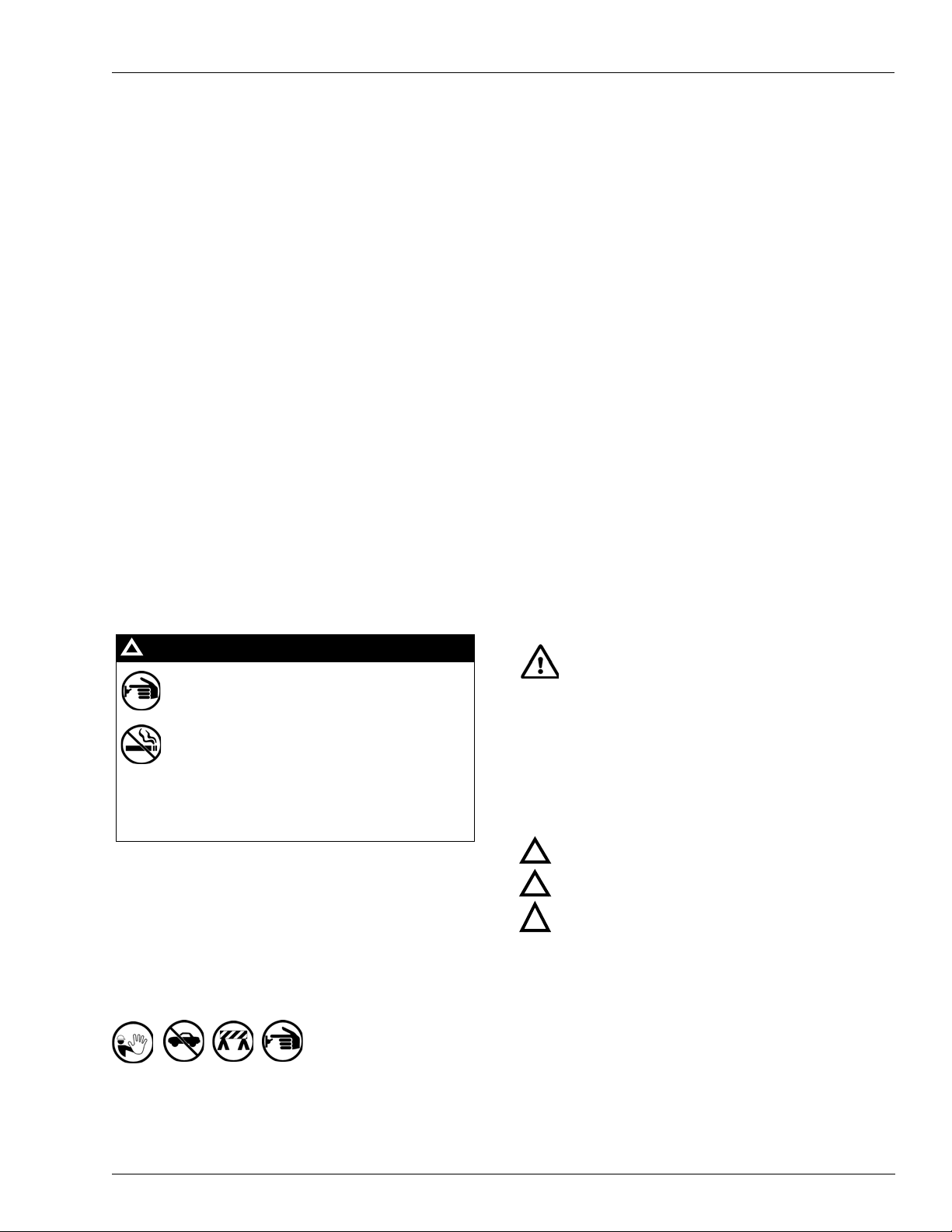
The EMERGENCY STOP, ALL STOP, and
PUMP STOP buttons at the cashier’s station
WILL NOT shut off electrical power to the
pump/dispenser. This means that even if you
activate these stops, fuel may continue to flow
uncontrolled.
You must use the TOTAL ELECTRICAL
SHUT-OFF in the case of an emergency and not
the console’s ALL STOP and PUMP STOP or
similar keys.
!
WARNING
!
Important Safety Information
Important Safety Information
Notes: 1) Save this Important Safety Information section
in a readily accessible location.
2) Although DEF is non-flammable, Diesel is
flammable. Therefore, for DEF cabinets that are
attached to Diesel dispensers, follow all the
notes in this section that pertain to flammable
fuels.
This section introduces the hazards and safety precau tions
associated with installing, inspecting, mainta ining or servicing
this product. Before performing any task on this prod uct, read
this safety information and the applicable sections in this
manual, where additional hazards and safety precau tions for
your task will be found. Fire, explosion, electrical shock or
pressure release could occur and cause death or serious injury,
if these safe service procedures are not followed.
Preliminary Precautions
You are working in a potentially dangerous environment of
flammable fuels, vapors, and high voltage or pressures. Only
trained or authorized individuals knowledgeable in the re lated
procedures should install, inspect, maintain or service this
equipment.
Emergency Total Electrical Shut-Off
The first and most important information you must know is how
to stop all fuel flow to the pump/dispenser and island. Locate
the switch or circuit breakers that shut of f all power to a ll fueling
equipment, dispensing devices, and Submerged Turbine
Pumps (STPs).
Read the Manual
Read, understand and follow this manual and any other labels
or related materials supplied with this equipment. If you do not
understand a procedure, call a Gasboy Authorized Service
Contractor or call the Gasboy Service Center at
1-800-444-5529. It is imperative to your safety and the safety of
others to understand the procedures before beginning work.
Follow the Regulations
Applicable information is available in National Fire Protection
Association (NFPA) 30A; Code for Motor Fuel Dispensing
Facilities and Repair Garages, NFPA 70; National Elec tric al
Code (NEC), Occupational Safety and Health Administration
(OSHA) regulations and federal, state, and local codes. All
these regulations must be followed. Failure to install, inspect,
maintain or service this equipment in accordance with these
codes, regulations and standards may lead to legal citations
with penalties or affect the safe use and operation of the
equipment.
Replacement Parts
Use only genuine Gasboy replacement p arts a nd retro fit kits on
your pump/dispenser. Using parts other than genuine Gasboy
replacement parts could create a safety hazard and violate
local regulations.
Safety Symbols and Warning Words
This section provides important information about warning
symbols and boxes.
Alert Symbol
Total Electrical Shut-Off Before Access
Any procedure that requires access to electrica l componen ts or
the electronics of the dispenser requires total electrical shut of f
of that unit. Understand the function and location of this switch
or circuit breaker before inspecting, inst alling, maintaining, or
servicing Gasboy equipment.
Evacuating, Barricading and Shutting Off
Any procedure that requires access to the pump/dispenser or
STPs requires the following actions:
• An evacuation of all unauthorized pers ons and vehicles
from the work area
• Use of safety tape, cones or barricades at the affected
unit(s)
• A total electrical shut-off of the affected unit(s)
MDE-5061 TopKAT™ Series 900 Replacement Report Printer Kit (M11810K001) Installation Instructions · March 2013 Page 3
This safety alert symbol is used in this manual and on
warning labels to alert you to a precaution which must be
followed to prevent potential personal safety hazards. Obey
safety directives that follow this symbol to avoid possible injury
or death.
Signal Words
These signal words used in this manual and on warning labels
tell you the seriousness of particular safety haz ards. The
precautions below must be followed to prevent death, injury or
damage to the equipment:
DANGER: Alerts you to a hazard or unsafe practice
!
which will result in death or serious injury.
WARNING: Alerts you to a hazard or unsafe practice
!
that could result in death or serious injury.
CAUTION with Alert symbol: Designates a hazard or
!
unsafe practice which may result in minor injury.
CAUTION without Alert symbol: Designates a hazard
or unsafe practice which may result in property or
equipment damage.
Working With Fuels and Electrical Energy
Prevent Explosions and Fires
Fuels and their vapors will explode or burn, if ignited. Spilled or
leaking fuels cause vapors. Even filling customer tanks will
cause potentially dangerous vapors in the vicinity of the
dispenser or island.
DEF is non-flammable. Therefore, explosion and fire safety
warnings do not apply to DEF lines.
Page 4

Important Safety Information
The pump/dispenser contains a chemical known to the
State of California to cause cancer.
WARNING
!
The pump/dispenser contains a chemical known to the
State of California to ca use birth defects or other
reproductive harm.
WARNING
!
Gasoline/DEF ingested may cause
unconsciousness and burns to internal organs.
Do not induce vomiting. Keep airway open.
Oxygen may be needed at scene. Seek medical
advice immediately.
WARNING
!
WARNING
!
DEF generates ammonia gas at higher temperatures.
When opening enclosed panels, allow the unit to air out to
avoid breathing vapors.
If respiratory difficulties develop, move victim away from
source of exposure and into fresh air. If symptoms persist,
seek medical attention.
Gasoline/DEF spilled in eyes may cause burns to
eye tissue. Irrigate eyes with water for
approximately 15 minutes. Seek medical advice
immediately.
WARNING
!
WARNING
!
Gasoline inhaled may cause unconsciousness
and burns to lips, mouth and lungs. Keep airway
open. Seek medical advice immediately.
WARNING
!
Gasoline spilled on skin may cause burns.
Wash area thoroughly with clear water.
Seek medical advice immediately.
WARNING
!
DEF is mildly corrosive. Avoid contact with eyes, skin, and
clothing. Ensure that eyewash stations and safety s howers
are close to the work location. Seek medical advice
recommended treatment if DEF spills into eyes.
WARNING
!
No Open Fire
Open flames from matches, lighters, welding torches
or other sources can ignite fuels and their vapors.
No Sparks - No Smoking
Sparks from starting vehicles, starting or using power tools,
burning cigarettes, cigars or pipes can also ignite fuels and their
vapors. Static electricity, including an electrostatic charge on
your body, can cause a spark sufficient to ignite fuel vapors.
Every time you get out of a vehicle, touch the metal o f your
vehicle, to discharge any electrostatic charge before you
approach the dispenser island.
Working Alone
It is highly recommended that someone who is capable of
rendering first aid be present during servicing. Familiarize
yourself with Cardiopulmonary Resuscitation (CPR) methods, if
you work with or around high voltages. This informa tio n is
available from the American Red Cross. Always advise the
station personnel about where you will be working, and caution
them not to activate power while you are working on the
equipment. Use the OSHA Lockout/Tagout procedures. If you
are not familiar with this requirement, refer to this information in
the service manual and OSHA documentation.
In an Emergency
Inform Emergency Personnel
Compile the following information and inform emergency
personnel:
• Location of accident (for example, address, front/back of
building, and so on)
• Nature of accident (for example, possible heart attack, run
over by car, burns, and so on)
• Age of victim (for example, baby, teenager, middle-age,
elderly)
• Whether or not victim has received first aid (for example,
stopped bleeding by pressure, and so on)
• Whether or not a victim has vomited (for example, if
swallowed or inhaled something, and so on)
Working With Electricity Safely
Ensure that you use safe and established practices in working
with electrical devices. Poorly wired devices may cause a fire,
explosion or electrical shock. Ensure that grounding
connections are properly made. Take care that sealing devices
and compounds are in place. Ensure that you do not pinch
wires when replacing covers. Follow OSHA Lockout/Tagout
requirements. Station employees and service contractors need
to understand and comply with this program completely to
ensure safety while the equipment is down.
Hazardous Materials
Some materials present inside electronic enclosures may
present a health hazard if not handled correctly. Ensure that
you clean hands after handling equipment. Do not place any
equipment in the mouth.
Page 4 MDE-5061 TopKAT™ Series 900 Replacement Report Printer Kit (M11810K001) Installation Instructions · March 2013
IMPORTANT: Oxygen may be needed at scene if gasoline has
been ingested or inhaled. Seek medical advice immediately.
Lockout/Tagout
Lockout/Tagout covers servicing and maintenance of machines
and equipment in which the unexpected energizatio n or start-up
of the machine(s) or equipment or release of stored energy
could cause injury to employees or personnel. Lockout/Tagout
applies to all mechanical, hydraulic, chemical or other energy,
but does not cover electrical hazards. Subpart S of 29 CFR Part
1910 - Electrical Hazards, 29 CFR Part 1910.333 contains
specific Lockout/Tagout provision for electrical hazards.
Page 5

Installing TopKAT Series 900 Replacement Report Printer Kit
Screws (4X)
Spacer
(Q10213-25)
(i)
(ii)
Screws (4X)
Printer Assembly
Installing TopKAT Series 900 Replacement Report Printer
Kit
To install the TopKAT Series 900 Replacement Report Printer Kit, proceed as follows:
1 Unlock and open the front and rear doors of the TopKAT unit.
2 Turn off the AC power switch located to the right when viewed from the rear of the head.
3 On the front bezel, disconne ct all cables to the existing Report Printer Assembly.
4 Remove and retain the four screws securing the existing printer/bracket to the bezel.
5 Remove the existing Printer/Bracket Assembly.
6 Install and secure the new Printer Assembly provided in the kit using the fours screws
removed in step 4.
Notes: 1) Ensure to align the new Printer
2) The Spacer (Q10213-25) pr ovided in the kit is r
the new bracket.
Assembly with the four screw holes.
equired under the lower left corner of
Figure 1: Installing New Printer Assembly
7 Remove the power supply cover marked W ARNING HIGH VOLT AGE by removing the three
screws that secure the cover.
MDE-5061 TopKAT™ Series 900 Replacement Report Printer Kit (M11810K001) Installation Instructions · March 2013 Page 5
Page 6

Installing TopKAT Series 900 Replacement Report Printer Kit
Existing Printer
Power Supply
DC OUT/TB2
AC IN/TB1
Bushing
24 V Power Supply
8 Disconnect the cables and remove the existing +5 V Printer Power Supply (C09370) located in
the lower left corner of the Power Supply Chassis Assembly (see Figure 2).
Figure 2: Existing +5 V Printer Power Supply
9 Install the new 24 V Power Supply (C09837) into the lower left corner of the Power Supply
Chassis Assembly.
Notes: 1) Orient the 24 V Power Supply so that the 4-position Connector
(DC) is to the left
and the 3-position Connector (AC) is to the right of the Power Supply Chassis
Assembly.
e
2) Secure the 24 V Power Supply with four scr
ws removed in step 4 on page 5.
10 Connect the AC Power Cable to the T erminal Block (TB) 1 power input connecto r on the 24 V
Power Supply .
Figure 3: Connecting AC Power Cable
Page 6 MDE-5061 TopKAT™ Series 900 Replacement Report Printer Kit (M11810K001) Installation Instructions · March 2013
Page 7

Installing TopKAT Series 900 Replacement Report Printer Kit
P2
P1
P3
11 Replace the existing Printer DC Power Cable (C06812) with the +24 V Power Supply Cable
(M11808A001) provided in the kit and perform the following steps:
a Plug in one end of +24 V Power Supply Cable to the 4-position DC OUT/TB2 on +24 V
Power Supply .
b Plug in the other end of +24 V Power Supply Cable to P3 on the Printer Interface Printed
Circuit Assembly [PCA (M11777A001)].
c Ensure to route the DC Connector through the bushing from left to right and then onto the
DC Output Connector (see Figure 3 on page 6). Failure to route the DC Conn
ector through
the bushing will not allow reinstalling the power supply cover without pinching the cable.
12 Connect the two connectors from the existing Printer Cable Assembly, the 10-position
Connector to P1 and the 6-position Connector to P2 as shown in Figure 4.
Figure 4: Attaching Power Cable to Printer Interface PCA
13 Verify the following settings on the new Printer Controller PCA (M11960A001):
JP1 JP2 JP3 JP4
Open Open Jumper 1-2 Jumper 1-2
Switches DIP 1
Pos 1 Pos 2 Pos 3 Pos 4 Pos 5 Pos 6 Pos 7 Pos 8 Pos 9 Pos 10
Off Off Off On Off On Off On On Off
MDE-5061 TopKAT™ Series 900 Replacement Report Printer Kit (M11810K001) Installation Instructions · March 2013 Page 7
Switches DIP 2
Pos 1 Pos 2 Pos 3 Pos 4 Pos 5 Pos 6 Pos 7 Pos 8
On Off Off Off Off Off Off On
Page 8

Installing TopKAT Series 900 Replacement Report Printer Kit
GND Test Point
VP Test Point
Paper Slot
Paper Roll
Paper Path
(ii)
(i)
Paper Pressure Level
14 Turn on the power and check for 24 V between Ground (GND) and Printer Voltage (VP) on
the new Printer Controller PCA [M11960A001 (see Figure 5)]. Adjust the supply to 24 V by
turning the potentiometer located on
the upper left corner of the printer power supply. Turn
clockwise to increase the voltage and counter-clockwise to decrease the voltage.
Figure 5: Installing New Printer Controller PCA
15 Reinstall the power supply cover and secure it with the three screws removed in step 7 on
page 5.
16 To load the paper, push Paper Pressure Level towards the front of the TopKAT unit (see
Figure 6), feed the paper about 3 inches into the paper slot, an
d then pull the Paper Pressure
Level back to the closed position.
Figure 6: Loading the Paper
Page 8 MDE-5061 TopKAT™ Series 900 Replacement Report Printer Kit (M11810K001) Installation Instructions · March 2013
Page 9

Installing TopKAT Series 900 Replacement Report Printer Kit
17 Close and lock the front and rear doors of the TopKAT unit.
Installation of the TopKAT Series 900 Replacement Report
Printer Kit is now complete.
MDE-5061 TopKAT™ Series 900 Replacement Report Printer Kit (M11810K001) Installation Instructions · March 2013 Page 9
Page 10

Phillips® is a registered trademark of Phillips Screw Company. TopKAT™ is a trademark of Gasboy International.
© 2013 GASBOY
7300 West Friendly Avenue · Post Office Box 22087
Greensboro, North Carolina 27420
Phone 1-800-444-5529 · http://www.gasboy.com · Printed in the U.S.A.
MDE-5061 TopKAT™ Series 900 Replacement Report Printer Kit (M11810K001) Installation In structions · March 2013
 Loading...