

Page 1
SERIES 8700Q
PUMPS AND DISPENSERS
INSTALLATION/OPERATION
MANUAL
038702
REV. 12/03/03
INSTALLERS - IMPORTANT
In addition to installation information, this manual contains warnings, safeguards
and procedures on the use and care of the Series 8700Q pumps. Please leave this
manual with the pump owner after the installation is complete.
The information in this document is confidential and proprietary. No further disclosure shall be made without
permission from Gasboy International LLC. Gasboy International LLC believes that the information in this document
is accurate and reliable. However, we assume no responsibility for its use, nor for any infringements of patents or
other rights of third parties resulting from its use. We reserve the right to make changes at any time without notice.
Copyright 2003 by Gasboy International LLC All rights reserved.
GASBOY INTERNATIONAL LLC LANSDALE, PA
Page 2

Gasoline and petroleum products are flammable. To avoid injury or death to persons or damage to equipment or
property, follow these listed warnings and other warnings and precautions outlined in this manual when installing, using,
or working around this equipment. Check with GASBOY Technical Services for compatibility of liquids with pump
materials.
TURN OFF AND LOCK OUT ALL POWER TO PUMP BEFORE PERFORMING SERVICE, MAINTENANCE OR IN THE EVENT
All products must be installed by a
qualified installer and used in
conformance with all building, fire, and
environmental codes and other safety
requirements applicable to its
installation and use, including, but not
limited to, NFPA 30, NFPA 30A, NFPA
395 & NFPA 70. A qualified installer is
familiar with fuel systems installations
under the above stated building, fire,
and environmental codes and other
safety requirements for the particular
type of installation.
This product is only part of a fuel
dispensing system and additional
equipment and accessories, such as,
but not limited to, breakaway
connectors, shear valves, pressure
regulators, flow limiters, and other
safety devices may be necessary to
meet the applicable codes.
For maximum safety, we recommend
that all employees be trained as to the
location and procedure for turning off
power to th e enti re system. Instru ctions
regarding proper operation of the
equipment along with the appropriate
safety warnings should be posted in
plain view at the fuel island.
Before performing service or
maintenance (including changing of fuel
filters or strainers) or in the event of a
fuel spill, turn off and lock out all power
to the system. In battery-powered
pumps, disconnect power source. In
submersible pump applications, turn off
and lock out power at the master panel
and close any impact valves to the
submersible pump and any other
dispensers which use that submersible
pump. AC power can feed back into a
shut-off dispenser when dispensers
share a common submersible pump or
starter relay. Also block islands so no
vehicles can pull up to the dispenser
when the dispenser is being worked on.
IMPORTANT WARNINGS AND SAFEGUARDS
OF A FUEL SPILL.
DO NOT use Teflon tape for any pipe
threads in the product.
DO NOT use consumer pumps for
pumping fuel or additives into aircraft.
DO NOT use commercial pumps for
direct fueling of aircraft without filters
and separators necessary to ensure
product purity.
DO NOT use where sanitary design is
required (for food products for human
consumption) or with water-based
liquids.
DO NOT smoke near the pump or when
using the pump.
DO NOT use near open flame or
electrical equipment which may ignite
fumes.
DO NOT permit the dispensing of
gasoline or other petroleum products
into a vehicle with its motor running.
DO NOT permit the dispensing of
gasoline or other petroleum products
into unapproved containers or into
approved containers in or on vehicles
includin g trucks. All contain ers must be
filled on the ground to prevent static
discharge. Always use Approved and
Listed hoses and nozzles with electric
pumps and dispensers.
DO NOT block open the nozzle in any
manner. Nozzles shall conform to UL
and NFPA code requirements for
attended or unattended service.
DO ensure that the pump is equipped
with proper filters based on the product
being dispensed and its intended use.
DO wear safety goggles and protective
clothes when dispensing any liquid
which may be potentially harmful or
hazardous.
DO keep all parts of body and loose
clothing clear of belts, pulleys, and other
exposed moving parts at all times.
DO require washing and changing of
clothes if fuel is spilled on a person or
his/her clothing. Keep away from open
flames, sparks, or people smoking.
DO provide a receptacle for catching
product from pump/meter when
servicing.
DO clean up product spills on the
driveway. Turn off and lock out all
power prior to cleanup.
DO insure pump is properly grounded.
DO insure hose is compatible with fluid
being dispensed.
DO inspect hose, nozzle, and pump on
a regular basis for wear, damage, or
other conditions which may create a
safety or environmental hazard.
DO make sure all pipe threads are
properly cut and the inside reamed to
remove burrs. Use UL classified
gasoline-resisting compound on all
joints of gasoline handling piping.
Sealing compound must also be
resistant to Gasohol (Ethanol and
Methanol). Use gasoline-resistant pipe
compound on male threads only; pipe
compound used on female threads can
be squeezed into the supply line where
it can enter the product stream and
become lodged in the pump or meter.
DO ensure that junction box covers are
in place and properly tightened. Mating
surfaces between the box and cover
must be free of dirt, nicks, and
scratches. All unused entries into the
junction box must be properly plugged.
035282 Rev. 1267
GASBOY INTERNATIONAL LLC.
707 North Valley Forge Rd. Lansdale, PA, 19446 ● (215) 855-4631 ● FAX: (215) 855-0341
Page 3

CONTENTS
IMPORTANT WARNINGS AND SAFEGUARDS FOR COMMERCIAL PUMPS
CONTENTS.....................................................................................................................Contents-1
INTRODUCTION...........................................................................................................................1-1
Purpose......................................................................................................................................1-1
General Description...................................................................................................................1-1
INSTALLATION............................................................................................................................2-1
Installation Precautions..............................................................................................................2-1
Foundation.................................................................................................................................2-2
Suction Pump.............................................................................................................................2-2
Remote Dispenser.....................................................................................................................2-2
Nozzle, Hose, And Accessories.................................................................................................2-3
Supply Line................................................................................................................................2-3
Single Pump/Remote Dispenser Dimensions............................................................................2-4
Twin Pump/Remote Dispenser Dimensions ..............................................................................2-5
011986 Base Layout, Model 8753QTW1...................................................................................2-6
011987 Base Layout, Model 8753QTW2...................................................................................2-7
011988 Base Layout, Model 8753QTW1M................................................................................2-8
011989 Base Layout, Models 8753Q.........................................................................................2-9
011990 Base Layout, Models 8753QXTW2.............................................................................2-10
011992 Base Layout, Model 8753QX......................................................................................2-11
011993 Base Layout, Model 8753QXTW1 ..............................................................................2-12
CONTROL LINES.........................................................................................................................3-1
Purpose......................................................................................................................................3-1
Grounding..................................................................................................................................3-1
Reset Motor Feed......................................................................................................................3-1
Pump Motor Feed......................................................................................................................3-1
Return........................................................................................................................................3-2
Submersible Feed, Submersible Drive ......................................................................................3-2
Reset Complete (Switch Detect)/Slow Flow ..............................................................................3-2
Fast Flow ...................................................................................................................................3-2
Light Feed..................................................................................................................................3-2
Phase 2 Feed.............................................................................................................................3-2
Pulser.........................................................................................................................................3-2
WIRING.........................................................................................................................................4-1
Wiring Precautions.....................................................................................................................4-1
Grounding..................................................................................................................................4-2
Circuit Breakers .........................................................................................................................4-2
The Pump Motor........................................................................................................................4-2
Motor Amp Ratings....................................................................................................................4-2
Wire Size....................................................................................................................................4-3
Conduit.......................................................................................................................................4-4
Wiring Diagrams ........................................................................................................................4-5
024212 Wiring Diagram.............................................................................................................4-6
024213 Wiring Diagram.............................................................................................................4-7
024214 Wiring Diagram.............................................................................................................4-8
024222 Wiring Diagram.............................................................................................................4-9
024223 Wiring Diagram...........................................................................................................4-10
024224 Wiring Diagram...........................................................................................................4-11
07/15/03 Contents-1
Page 4

GASBOY Series 8700Q
PULSERS......................................................................................................................................5-1
General......................................................................................................................................5-1
Wiring.........................................................................................................................................5-1
Reed Pulsers .............................................................................................................................5-2
Electronic Pulsers......................................................................................................................5-3
START-UP ....................................................................................................................................6-1
Completion Check List...............................................................................................................6-1
Start-Up......................................................................................................................................6-1
Post Start-Up Tests....................................................................................................................6-2
Power Reset External Adjustment.............................................................................................6-3
Changing The Price...................................................................................................................6-4
OPERATING SEQUENCE............................................................................................................7-1
Pump..........................................................................................................................................7-1
Remote Dispenser.....................................................................................................................7-1
PREVENTIVE MAINTENANCE....................................................................................................8-1
General......................................................................................................................................8-1
Hints For Better Pump Performance..........................................................................................8-1
Preventive Maintenance Check List...........................................................................................8-2
Contents-2 07/15/03
Page 5

Section 1
INTRODUCTION
PURPOSE
The GASBOY Series 8700Q Pumps and Dispensers Installation/Operation Manual is provided to
assist the installer in installing and operating the unit. This manual should be supplied to the
electrician prior to the installation of conduit and wiring to ensure the Series 8700Q dispensing unit
is installed properly. Faulty installations are the major cause of unit malfunctions. The unit must
be installed and operated as described in this manual to ensure the reliability and proper operation
of the Series 8700Q dispensing unit. In addition to installation information, this manual contains
warnings, safeguards and procedures on the use and care of the Series 8700Q pumps and
remote dispensers. Be sure to leave this manual with the pump/dispenser owner after the
installation is complete.
☎ Customers and installers having any questions pertaining to the installation should
contact their GASBOY distributor.
GENERAL DESCRIPTION
The GASBOY Series 8700Q dispensing units are UL-listed and are available in a self-contained
(suction pump) package or in a remote-controlled (dispenser) package. Both packages offer a
variety of models which are available as single hose outlets or dual hose outlets (with single or
dual product capability). The self-contained models are available in standard speed, up to 15
GPM/56 LPM; in high speed or up to 22 GPM/83 LPM. The rate of delivery for the remotecontrolled packages will vary according to the size of the submersible pump. The delivery rate of
both packages will also vary depending upon installation conditions and added accessories.
The Series 8700Q offers the following features:
At a glance:
Suction Pumps Remote Dispensers Features
Standard
Speed
Models
High
Speed
Models
8752Q
8752QTW1
8752QTW2
8753Q
8753QTW2
8753QTW1M
8752QX
8752QXTW1
8752QXTW2
8753QX
8753QXTW1
8753QXTW2
Inlet: 1-1/2" NPT
Discharge: 3/4" NPT (female threads)
Motor: 3/4 HP continuous duty
Valves (dispenser only): 1"
Inlet: 1-1/2" NPT
Discharge: 1" NPT (female threads)
Motor: 3/4 HP continuous duty
Valves (when used): 1"
07/15/03 1-1
Page 6

GASBOY Series 8700Q
Other standard features and specifications of the Series 8700Q are:
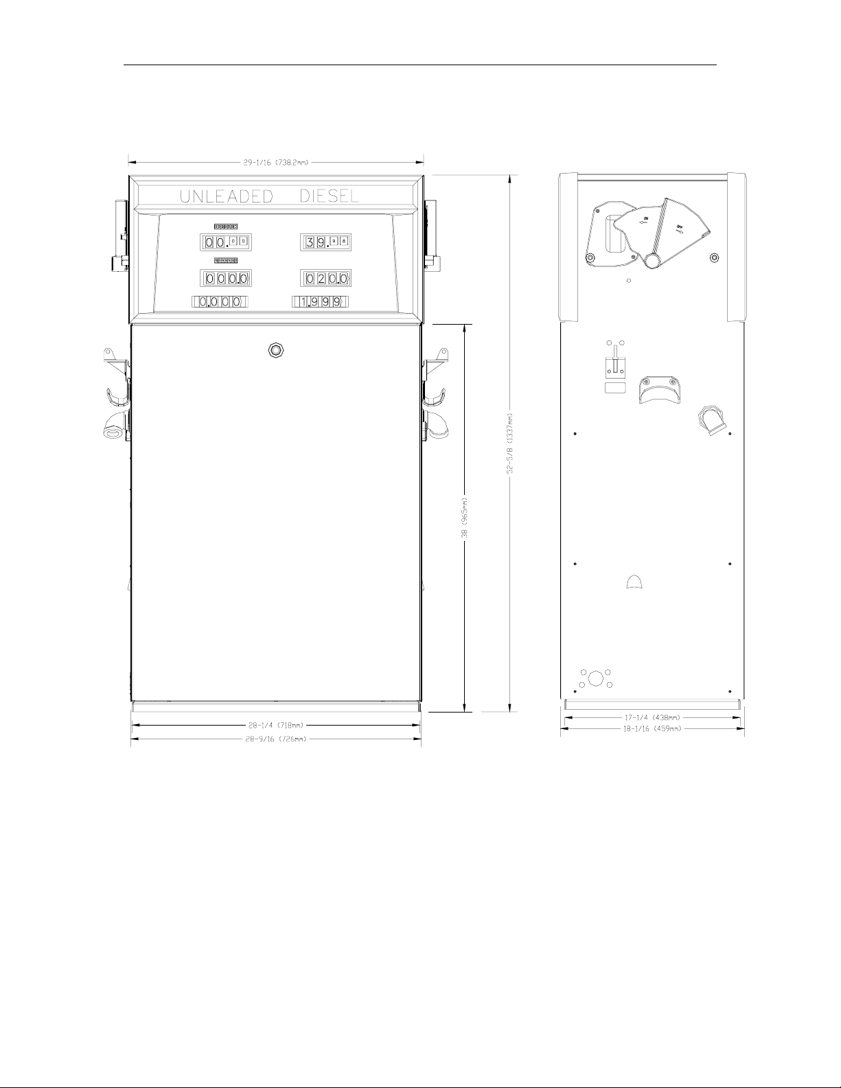
• Cabinet: Painted black top and sides, white front and rear doors and white dial enclosures.
Dimensions are 29-1/16"W, 18-3/8"D, 52-5/8"H.
• Meter: Four piston, positive displacement.
• Pump: Belt-driven, positive-displacement rotar y vane with an 80 mesh (300 micron) strainer
and integral air separation.
• Motor: (See chart earlier in this section).
• Electric reset with a reset complete (switch detect) lead. When used with optional pulser
outputs, allows fueling to be monitored by an automated fuel management system.
• Two stage electric solenoid valves (on all remote dispensers and 8753QTW1)
• Island-oriented nozzle boots.
• UL-Listed hose assembly, 3/4"x 12’ for standard speed; 1" x 12’ for high and super speed.
• Designed to support UL-Listed Interchangeable service station nozzles (not included).
• Hose hangers.
• Mechanical full-computing register with electric reset Mechanical pump registers show
the total currency amount for a delivery, the total volume for a delivery, and the price per unit.
All computers read up to 999.9 gallons or liters. The standard computer (Veeder-Root
VR10/4) reads up to $99.99 per sale with a price that may be set up to $3.99 per gallon/liter.
The high capacity computer (VR10) will read up to $999.99 per sale with a price that may be
set up to $5.999 per gallon/liter. The volume and currency registr ation will vary according to
the order.
• Mechanical totalizers, money and volume totalizers for each hose, records up to 9,999,999.9
liters or gallons and money up to $999999.99 units of currency.
• Fluids: Gasoline, diesel, kerosene. Not suitable for methanol/ethanol blends.
• Agencies: UL, CUL, W&M.
Optional accessories:
10:1, 100:1 money or volume pulsers
internal hose retractor
inlet check valve on suction pumps
internal fuel filter adapter
lighted displays
solenoid valves
satellite piping
stainless steel exterior
230 or 380VAC operation
liter registration
manual hand crank
Listed automatic nozzles
special lengths of hose
Listed swivels and breakaways
spin-on filter elements
special painting
Listed emergency shutoff valves
Listed pressure regulating valve for aboveground tank applications used with suction pumps.
1-2 07/15/03
Page 7

Section 2
INSTALLATION
INSTALLATION PRECAUTIONS
All installations must conform with all building/fire codes, all Federal, State, and Local codes,
National Electrical Code, (NFPA 70), NFPA 30, and Automotive and Marine Service Station Code
(NFPA 30A) codes and regulations. Canadian users must also comply with the Canadian
Electrical Code.
Plan your installation carefully. A pump/remote dispenser cannot be expected to work
satisfactorily unless the underground installation is correct. Dispensing troubles, which seem to be
pump-related, are frequently traced to faulty installation. Review the following list of installation
DO’s and DON’T’s to avoid potential problems:
1. DO read the WARNINGS page at the front of this manual, preceding the Table of Contents.
It contains important information regarding the safe use of your dispensing equipment.
2. DO install an emergency power cutoff. In addition to circuit breaker requirements of NFPA 70
and NFPA 30A, a single control which simultaneously removes AC power from all site
dispensing equipment is recommended. This control must be readily accessible, clearly
labeled, and in accordance with all local codes.
In a fuel management system application, the EMERGENCY STOP and STOP keys on the
console and/or the optional EMERGENCY STOP button on the Island Card Reader do not
remove AC power from equipment and under certain conditions, will not stop product flow.
In order to provide the highest level of safety to you, your employees, and customers, we
recommend that all employees be trained as to the location and procedure for turning off
power to the entire system.
3. DO have the pump/remote dispenser installed by a competent installer/electrician.
4. DO install breakaway coupling on discharge hose. If using a high hose retriever, install
breakaway approximately 12" downstream of hose clamp on nozzle side of clamp.
5. DO NOT experiment with a pump if you are not sure the installation is correct.
6. DO NOT overload sub- or main breaker panels.
7. DO NOT install any underground piping without proper swing joints. (Always use shoulder
nipples, never close nipples).
8. DO NOT cover any lines until they have been both air- and liquid-tested.
9. DO NOT back-fill the tank or supply line with cinders or ashes. (Back-fill with clean sand,
crushed rock, or pea gravel).
10. DO NOT use black iron pipe or fittings for underground installations. (Use only new
galvanized or fiberglass* pipe and fittings). *Install all fiberglass pipe and fittings according to
manufacturer’s specifications and requirements.
11. DO NOT use power line wiring of inadequate capacity. (Use gauge specified by the wiring
diagram or wire chart provided in Section 4).
12. DO NOT use a circuit breaker of improper size. (See Section 4).
13. DO NOT install fill pipe to tank where it can be submerged with standing water.
12/03/03 2-1
Page 8

GASBOY Series 8700Q
14. DO NOT use the GASBOY fuel dispensing equipment to remove water ballast from the
storage tank.
15. DO NOT use gaskets on covers of explosion-proof type boxes. The sealing compound found
around wires at various locations within conduit is a requirement of the National Electrical
Code and should not be disturbed. Ensure that the mating surfaces between the junction box
and cover are free of dirt, debris, nicks and scratches. Tighten junction box covers befor e
replacing panels.
16. DO NOT use knock-out boxes or flexible conduit for installing this unit. All power and lighting
wires should be run in threaded, rigid, metal conduit. All threaded connections must be
drawn up tight with five (5) threads minimum engagement. Only one opening in the AC
junction box is provided with a plug at the factory. At completion of the installation, it is the
installer’s responsibility to ensure that any unused openings are plugged.
FOUNDATION
Make sure that your installation conforms to the applicable codes required by Federal, State, and
local agencies concerning secondary containment underneath the dispenser. Follow the
installation requirements of the secondary containment manufacturer to ensure that your site is
environmentally safe and to minimize the entrance of water under the dispenser.
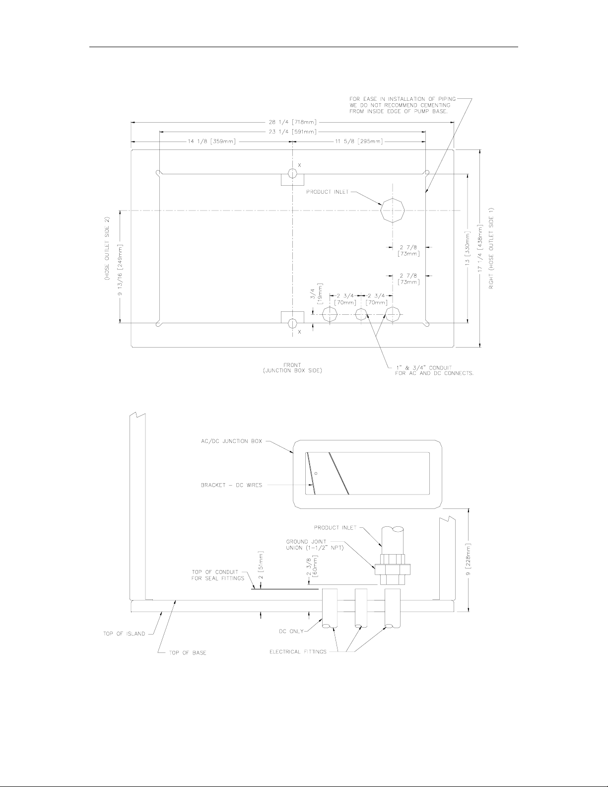
Secure the pump/remote dispenser to the island using anchor bolts through the two mounting
holes, which are 13 inches (330mm) apart and are indicated on each base layout. If the
dispensing unit is not securely fastened to the island, supply line leaks at unions and pipe joints
may occur. Use one of two types of bolts to anchor the pump to the island. Use two (2) 1/2" x 5"
(13mm x 125mm) machine bolts imbedded in the concrete, or, to meet minimum UL and API
requirements for universal interchangability of pumps, use two 1/2" x 3 1/2" (13mm x 90mm) lag
screws with 2" (51mm) expansion shields.
SUCTION PUMP
The pump and the tank should be located close to each other with as few changes in direction of
the supply line, as possible. This reduces the possibility of vaporization (gasoline only), attains the
highest possible flow rate, and results in a lower installation cost. Avoid long supply lines and
excessive vertical lifts. The dynamic lift for this unit is rated at 12 feet (3.66m) for gasoline and 13
feet (3.96m) for diesel and can vary according to conditions of the installation and fuel
temperature.
If a pump is to be used with an above-ground tank, a pressure regulator valve is required on the
suction side of the pump; consult your GASBOY representative for details. The tank should be
free of water and dirt. It is recommended that the tank be pressure tested to verify it is tight.
NOTE: T he outlet fitting at the top of the float chamber should be connected to drain back to the
storage tank. The pipe size for the return line to the storage tank should be at least 3/8"
(9.525mm).
REMOTE DISPENSER
Locate the remote dispenser and tank with submersible pump as close to each other as possible
to attain minimum possible pressure drop and the highest possible flow rate, consistent with the
pump capacity. Consult the submersible pump manufacturer’s recommendations for pipe sizing
and installation instructions pertaining to the model of submersible pump being installed.
2-2 12/03/03
Page 9

Installation
A Listed emergency shut-off valve (OPW 10RUS or equal) must be installed under each remote
dispenser with the shear groove at the same level as the top of the concrete island +
1/2"
(12.7mm). The shutoff valve should be rigidly supported to insure proper shearing and closure of
the valve in the event the remote dispenser is dislodged. According to the type of shear valve, a
different supply nipple may be required.
After a shear valve h as operated on an emergency basis from f ire or mechanical shock, o r
if it does not operate co rrectly when inspected, repairs must be made before putt ing the
remote dispenser into service.
It is required by the Flammable and Combustible Liquids Code that a leak detector be installed in
the system to prevent underground leaks from going unnoticed.
NOZZLE, HOSE, AND ACCESSORIES
This unit is normally equipped for use with a UL-Listed interchangeable service station type
nozzle. Only UL-Listed hose assemblies and accessories are to be used with this device. A
Listed breakaway connector must be installed on all hose assemblies.
SUPPLY LINE
Use new galvanized or fiberglass (see note) pipe, 1 1/2" (38.1mm) minimum diameter.
NOTE: Fiberglass pipe is to be installed according to manufacturer’s specifications and
requirements.
Be sure both the pipe and the tank are clean. Foreign matter entering the pump can cause
extensive damage. Obstructions in the supply line can create pump problems and reduced flow
rate.
Make sure all pipe threads are properly cut and the inside reamed to remove burrs. Use Listed
gasoline-resistant compound on all joints of gasoline handling piping. Sealing compound must
also be resistant to Gasohol (Ethanol and Methanol). Do not use Teflon Pipe Sealing Tape. Use
gasoline-resistant pipe compound on male threads only; pipe compound used on female threads
can be squeezed into the supply line where it can enter the product stream and become lodged in
the pump or meter. Install swing joints under the pump and at the tank to avoid breaks in the
supply line from settling or frost heave.
To avoid product delivery problems on suction pumps, be sure there are no traps in the supply
line. Supply lines, for both suction pumps and submersible pumps, should go straight down
beneath the pump to a point 18 inches (45.7cm) below the ground level and pitch at a rate of 1/8
inch (3.18mm) per foot (.305m) from there down to the storage tank. The supply line should be as
short and direct as possible with swing joints at all turns. Support the horizontal run of pipe at 10foot intervals to maintain pitch and prevent traps. Do not use wood as pipe supports.
New EPA regulations require that only one check valve be used per supply line and located
directly below, and as close as practical to the suction pump. Do not use spring-loaded or union
check valves since these will unnecessarily reduce the flow rate and contribute to the reduction of
atmospheric pressure necessary to keep gasoline in a liquid state.
Upon completion of installation, all liquid-carrying lines must be checked for leaks.
12/03/03 2-3
Page 10

GASBOY Series 8700Q
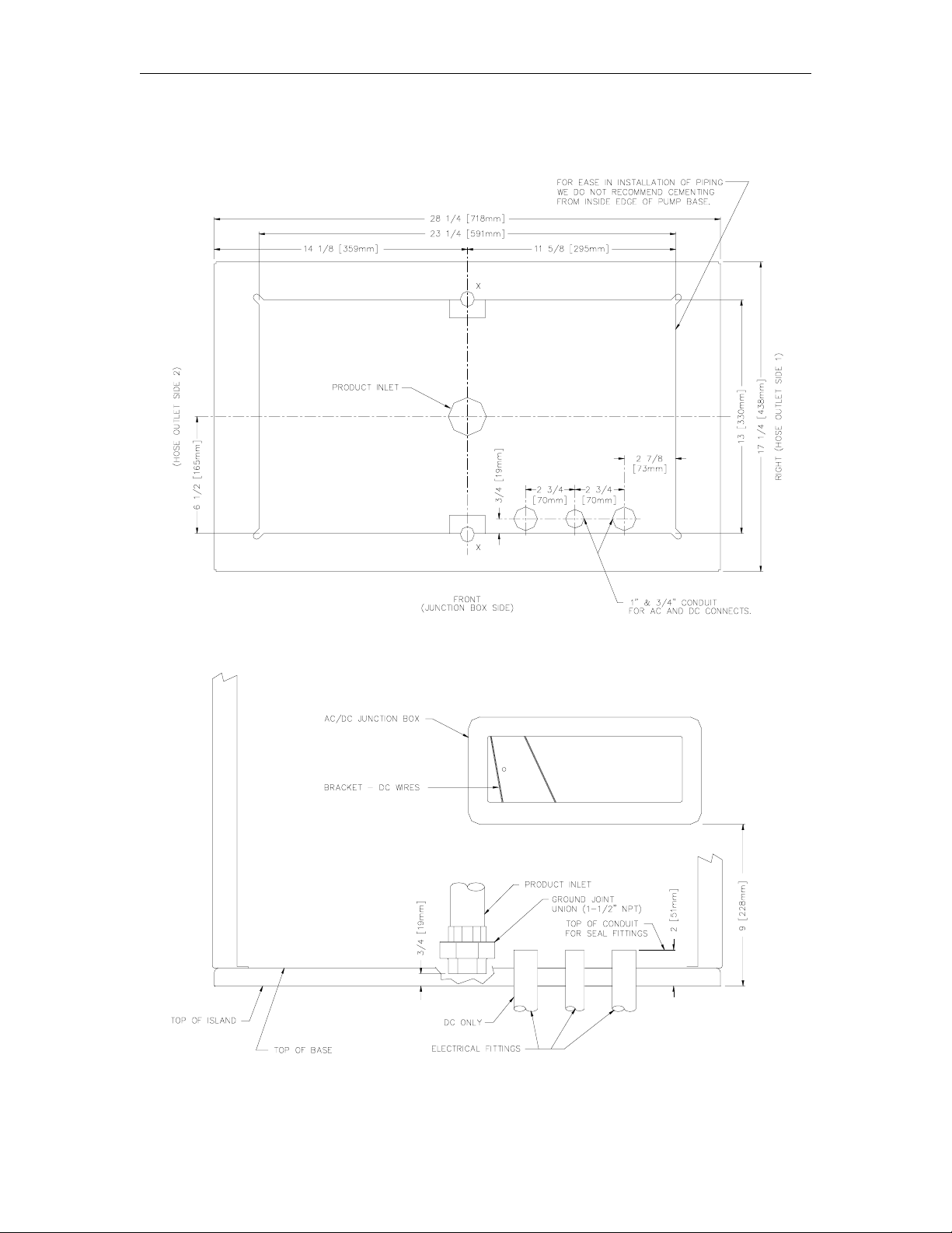
SINGLE PUMP/REMOTE DISPENSER DIMENSIONS
2-4 12/03/03
Page 11
Installation
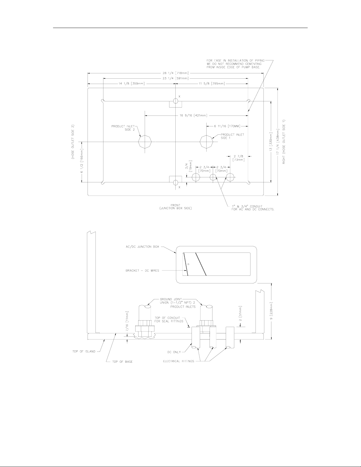
TWIN PUMP/REMOTE DISPENSER DIMENSIONS
12/03/03 2-5
Page 12
GASBOY Series 8700Q
011986 BASE LAYOUT, MODEL 8753QTW1
2-6 12/03/03
Page 13
Installation
011987 BASE LAYOUT, MODEL 8753QTW2
12/03/03 2-7
Page 14
GASBOY Series 8700Q
011988 BASE LAYOUT, MODEL 8753QTW1M
2-8 12/03/03
Page 15

Installation
011989 BASE LAYOUT, MODEL 8753Q
12/03/03 2-9
Page 16

GASBOY Series 8700Q
011990 BASE LAYOUT, MODEL 8753QXTW2
2-10 12/03/03
Page 17

Installation
011992 BASE LAYOUT, MODEL 8753QX
12/03/03 2-11
Page 18

GASBOY Series 8700Q
011993 BASE LAYOUT, MODEL 8753QXTW1
2-12 12/03/03
Page 19

Section 3
CONTROL LINES
PURPOSE
This section is provided to familiarize the installer with the control inputs and outputs that are
available for the Series 8700Q dispensing unit. It is recommended the installer read these
descriptions to obtain a better working knowledge of the unit in order to guide him in planning the
site wiring. Reference Section 4 for specific wiring diagrams and installation notes.
The Series 8700Q may be provided for use with 230 VAC power for international applications.
The operating voltage for control lines to these units is shown in parentheses as (230 VAC Int’l).
GROUNDING
To ensure proper operation of the equipment and provide the necessary safety factors, a good
ground line must be provided. A ground wire (prefer ably green) must be connected between the
unit’s AC junction box ground lug and the main electrical service panel. One (1) earth ground
connection is required per unit. The ground rod is to be a solid, corr osion-resistant conductor and
must be installed at the main electrical panel in accordance with the National Electrical Code. It
should be properly tied into the ground bus strip of the panel. We recommend the neutral and
ground bus strips be bonded together (unless prohibited by local codes).
RESET MOTOR FEED
The reset motor feed is a 115 VAC (230 VAC Int’l) input which is supplied through the pump
handle switch to activate the reset motor. Without power supplied to this line, the unit will not reset
when the pump handle is turned on. Two feed lines are provided for twins. This feed is also
connected to the input of one of the internal switches of the electric reset. When the reset finishes
its cycle, the 115 VAC (230 VAC Int’l) input to the switch will be passed through as an output
causing the solenoid valve (optional in some models) to open and the reset complete line to
indicate 115 VAC (230 VAC Int’l).
PUMP MOTOR FEED
The pump motor feed is a 115 VAC (230 VAC Int’l) input which is supplied to the input side of one
of the internal switches of the electric reset. When the reset finishes its cycle, the 115 VAC (230
VAC Int’l) input to the switch is passed through as an output causing the pump motor to receive
power and begin running. Without power to this line, the unit would reset, but be unable to fuel.
Two feed lines are provided in twins which contain two motors. The gauge of this wire (and its
neutral wire) should be determined according to the size of the motor, the voltage at which the
motor will be powered (115VAC or 230VAC), and the distance from the breaker panel to the
pump. It is possible to combine the pump motor feeds for twins and supply them from one
breaker; however, the gauge of the wire needs to be adjusted to handle the load of two motors.
07/15/03 3-1
Page 20

GASBOY Series 8700Q
RETURN
The return is the AC current return line back to the breaker panel for all attached devices (pump
motor, reset motor, solenoid valves). The gauge of this wir e should be equal to that of the pump
motor feed (suction pumps) or submersible feed (remote dispensers). This wire is commonly
referred to as the neutral wire.
SUBMERSIBLE FEED, SUBMERSIBLE DRIVE
The submersible feed is a 115 VAC (230 VAC Int’l) input which is supplied to the input side of one
of the internal switches of the electric reset. When the reset finishes its cycle, the 115 VAC (230
VAC Int’l) input to the switch is passed through as an output (submersible drive) to drive a starter
relay or to directly drive a submersible motor up to 1 HP at 115VAC/230VAC. Any submersible
motor exceeding this limitation must use a starter relay.
RESET COMPLETE (SWITCH DETECT)/SLOW FLOW
The reset complete is a 115 VAC (230 VAC Int’l) output which is used to indicate the reset is
complete and the dispensing unit is ready to dispense product. Two lines are provided for twins.
This line should only be used when monitoring of the dispensing unit is desired as when used with
a Fuel Management System. This line must be capped when not in use. This line is connected to
the slow flow stage of the solenoid in the pump.
FAST FLOW
This is a 115 VAC (230 VAC Int’l) input which controls the fast flow valve of the pump/remote
dispenser (when a slow/fast flow valve is available) If slow/fast flow control is not desired, this line
should be tied to the reset complete/slow flow line. The line should be switched through the fuel
management system and only be on when the pump/remote dispenser is authorized and the
pump/remote dispenser should be in fast flow mode. This line will be switched on when the
pump/remote dispenser is in the manual mode.
LIGHT FEED
The light feed is a 115 VAC (230 VAC Int’l) input required to power the fluorescent lights. In a site
configuration using multiple remote dispensers (or pumps), the power for the lights of up to 8 units
can be supplied by 1 breaker. If separate control of the lights is not desired, the light feed for each
dispensing unit may be taken from its Reset Motor Feed.
LIGHT NEUTRAL
The light neutral is a return line for AC current from the lights to the breaker panel. When a
separate breaker is not used to control the lights, the light neutral is attached to the neutral which
is connected to the reset motor.
PHASE 2 FEED
The phase 2 feed is a hot feed which is the opposite phase of the pump motor feed. This line and
the pump motor feed are used for domestic 230VAC motor applications.
PULSER
The pulser supplies a DC output which is provided to indicate the quantity dispensed. Pulsers are
optional and are only used when monitoring of the dispensing unit operation is desired as when
used with a fuel management system.
3-2 07/15/03
Page 21

Section 4
WIRING
☎ Customers and installers having any questions pertaining to the installation should
contact their GASBOY distributor.
WIRING PRECAUTIONS
The quality of the electrical installation is a major factor in maintaining proper safety levels and
providing trouble-free operation of your GASBOY pump/remote dispenser. To assure a quality
installation, follow these rules:
1. All wiring must be installed to conform with all building/fire codes, all Federal, State, and
Local codes, National Electrical Code, (NFPA 70), NFPA 30, and Automotive and Marine
Service Station Code (NFPA 30A) codes and regulations. Canadian users must also comply
with the Canadian Electrical Code.
2. Use only threaded, rigid, metal conduit.
3. Use only UL-labeled insulated gasoline- and oil-resistant stranded copper wiring of the proper
size.
4. Wire connections should be tightly spliced and secured with a wire nut; close off the open end
of the wire nut with electrical tape.
5. The line to the motor should be on a separate circuit and installed on a 20 to 30 AMP breaker
depending on the motor size and/or the voltage setting.
6. Install an emergency power cutoff. In addition to circuit breaker requirements of NFPA 70
and NFPA 30A, a single control which simultaneously removes AC power from all site
dispensing equipment is recommended. This control must be readily accessible, clearly
labeled, and in accordance with all local codes.
In a fuel management system application, the EMERGENCY STOP and STOP keys on the
console and/or the optional EMERGENCY STOP button on the Island Card Reader do not
remove AC power from equipment and under certain conditions, will not stop product flow.
In order to provide the highest level of safety to you, your employees, and customers, we
recommend that all employees be trained as to the location and procedure for turning off
power to the entire system.
To reduce the risk of electrical shock when servicing, turn off all power to
the pump/remote dispenser. In submersible pump applications, turn off
power to the submersible pump and any other remote dispensers which
use that submersible pump. AC power can feed back into a shut-off
dispenser when dispensers share a common submersible pump or starter
relay.
7. Have the pump/remote dispenser installed by a competent installer/electrician.
WARNING:
09/23/03 4-1
Page 22

GASBOY Series 8700Q
GROUNDING
To ensure proper operation of the equipment and provide the necessary safety factors, this unit
must be grounded. A ground wire (preferably green) must be connected between the unit’s AC
junction box ground lug and the main electrical service panel. One (1) ear th ground connection is
required per unit. The ground rod is to be a solid, corrosion-resistant conductor and must be
installed at the main electrical panel in accordance with the National Electrical Code. It should be
properly tied into the ground bus strip of the panel. We recommend the neutral and ground bus
strips be bonded together (unless prohibited by local codes).
CIRCUIT BREAKERS
Power to the unit should be supplied from a dedicated breaker . No other equipment should be
powered from this breaker. Remote dispensers may be grouped together on a single breaker
when the submersible pump has its own breaker. It is recommended that no more than two
remote dispensers be powered from one breaker to maintain isolated control with the circuit
breaker panel in case of problems. Units directly driving pumps (suction or submersible) should
be supplied power from a separate breaker. A tag on the motor identifies the maximum current
draw of the motor. If two (2) pumps are supplied from one br eaker, that breaker must be capable
of handling the load of both motors. In cases where multiple r emote dispensers supply power to a
single submersible pump, all breakers controlling the remote dispenser must be on the same
phase of power. Failure to do this will damage the equipment. Provisions must be made to break
both legs of any AC circuit.
THE PUMP MOTOR
Pumps are shipped from the factory with motors wired according to the specifications given on the
order as to kind of current, frequency and voltage.
Very often on installation, it becomes necessary to change the original setting to suit the AC power
source. To do this, locate the motor change-over plate, typically located on the shaft end of the
motor, and remove the screw which secures it in place. Slide the plate so that the desired voltage,
as marked on the plate, lines up with the screw hole. Reinsert the scr ew and secure the plate in
place.
Many motor failures result from improper setting of the motor change-over plate. If set for 115
VAC and a 230 VAC feed is used, the motor will burn out after running only a short time. If set for
230 VAC and a 115 VAC feed is used, the motor will run very slowly and the starting field will soon
burn out.
MOTOR AMP RATINGS
The following chart shows the maximum running amperage that can be expected for each pump
motor, unless noted otherwise:
Models 115v/60hz units 230v/60hz units 230v/50hz units
8753QTW1, 8753Q, 8753QTW2,
8753QTW1M
NOTES:
1. These numbers do not account for the higher load upon startup, nor up to one additional amp
associated with other electrical components (lights, solenoid valves, etc.).
2. The 8753QTW2 and 8753QTW1M have one pump motor per side.
10.0 5.0. 6.0
4-2 09/23/03
Page 23

Wiring
WIRE SIZE
The table below shows the required AC wire size for suction and submersible pumps based on the
HP rating of the pump motor and the distance from the circuit breaker to the pump/remote
dispenser for both 115 and 230 volt units. Use this table as a guide for selecting the proper size
wire for the Pump Feed, Phase 2 Feed, and Return.
The table also applies to the Disp Feed, and Subm Drive of a dispenser when the submersible
pump is directly driven via the dispenser control circuitry. A starter relay must be used; however,
when the submersible pump motor is greater than 1 HP at 115 VAC or 2 HP at 230 VAC. When
using a starter relay for the pump motor, the control lines to the dispenser may be 12 AWG.
The AC wire size of the control lines of a pump (Reset Motor F eed, Pump Motor Feed, Neutral
Feed, Phase 2 Feed) or remote dispenser (Reset Motor Feed, Submersible F eed, Submersible
Drive, Neutral Feed) should be 12 AWG unless you are using a starter relay. A starter relay must
be used whenever the submersible motor is greater than 1 HP at 115/230 VAC.
If multiple units are powered from the same breaker through the same wires, you must increase
the gauge of the wires to handle the added load according to the distance from the breaker panel
and the HP rating (if applicable).
The AC wire size for the Light Feed and Light Neutral, when the lights ar e wired from a single
dedicated breaker, should be 14 AWG for distances up to 300 feet (91.4m) or 12 AWG for
distances over 300 feet (91.4m).
The AC wire size for the Reset Complete (Switch Detect) and Fast Flow lines should be 14 AWG
(when they are used).
The DC wire size for the Pulser lines must be 18 AWG (when they are used). Shielded cable as
described in the Pulser section allows pulser lines to be run with the AC wires.
Wire Size
09/23/03 4-3
Page 24

GASBOY Series 8700Q
CONDUIT
All wiring to the GASBOY Series 8700Q dispensing unit must be installed in threaded, rigid, metal
conduit. PVC is not acceptable. When the Series 8700Q dispensing unit is used with a
GASBOY fuel management system, it is recommended that AC power wires be installed in a
separate conduit from the DC pulser; they should not run in any sort of common conduit or tr ough.
However, if AC and DC power wires share conduit, pulser wiring must use the cable as specified
in the Pulsers section.Wiring between a Fuel Point Reader (FPR) and its pre-amp junction box is
intrinsically safe and must be run in a conduit with only other intrinsically safe wiring. It cannot be
run in conduit with AC, DC, RS-485, or pulser wiring, regardless of the cable type used. See the
Fuel Point Reader Installation and Retrofit Manual, C35628 for details.
When using a fuel management system other than a GASBOY system, see the manufacturer’s
installation manual for specific conduit requirements.
All wiring and conduit runs must also conform with the National Electrical Code (NFPA 70) and the
Automotive and Marine Service Station Code (NFPA 30A). All wiring and conduit runs must
conform to local codes. Canadian users must also comply with the Canadian Electrical Code.
Use the charts below as a guideline to determine the proper conduit sizes for the GASBO Y Ser ies
8700Q dispensing unit. When planning the orientation of the wiring runs, follow the applicable
GASBOY wiring diagram and consider the layout of the components at the site. Long runs or a
large number of bends may require you to increase conduit size over what is listed.
To determine conduit size needed, use the THHN/THWN Wire Areas table (left) to find the area
for each wire gauge. Add up all wire areas. Use the Areas of Tr ade Size Conduit Table (right) to
select the smallest number in the 25% fill area (based on NEC 501-1) that comes closest without
exceeding the total wire area.
4-4 09/23/03
Page 25

Wiring
WIRING DIAGRAMS
The following pages contain wiring notes and wiring diagrams. Consult the appropriate wiring
diagram for your pump/remote dispenser model and follow all notes.
Wiring diagrams are presented in numerical order. Wiring diagram 024214 has two diagrams: one
for simultaneous operation of master and satellite and one for non-simultaneous operation. Be
sure to use the correct one for your application.
NOTES:
1. All wiring and conduit runs must conform with all building/fire codes, all Federal, State, and
Local codes, National Electrical Code, (NFPA 70), NFPA 30, and Automotive and Marine
Service Station Code (NFPA 30A) codes and regulations.
2. When wiring pumps, for 115 VAC applications, motors can be wired as 230 VAC to reduce
current draw. See breakaway view of Optional 230 VAC Motor. The selector switch should
be set to the 230 V position. All other wiring should remain the same except for the addition
of the L2 (requires 230 VAC breaker for control).
3. When wiring remote dispensers, submersible starter relays are always recommended when a
submersible pump is used; however, the control circuit is capable of directly driving a
submersible pump up to 1 HP at 115/230 VAC. Any pump over these ratings will require a
submersible starter relay.
4. If using a satellite for fueling, see Weights and Measures Handbook 44 to determine which
mode of satellite operation is relevant for your application. In many cases, the satellite must
be wired so it cannot dispense product while the master remote dispenser is dispensing and
vice versa. Use the correct wiring diagram according to your application.
5. If combining a remote dispenser with a fuel management system, the maximum HP limitation
for directly driving a remote dispenser without the use of an additional relay or submer sible
starter must be the lower of the two components.
6. Use the wire size chart listed on page 4-3 when determining the wire size for the control
wiring.
09/23/03 4-5
Page 26

GASBOY Series 8700Q
024212 WIRING DIAGRAM
Models: 8753QX
4-6 09/23/03
Page 27

Wiring
024213 WIRING DIAGRAM
Models: 8753QXTW1
8753QXTW2
09/23/03 4-7
Page 28

GASBOY Series 8700Q
024214 WIRING DIAGRAM
Models: Satellite Island-Oriented Nozzle (side), 216A/8753QX
4-8 09/23/03
Page 29

Wiring
024222 WIRING DIAGRAM
Models: 8753QTW2
8753QTW1M
09/23/03 4-9
Page 30

GASBOY Series 8700Q
024223 WIRING DIAGRAM
Models: 8753QTW1
4-10 09/23/03
Page 31

Wiring
024224 WIRING DIAGRAM
Models: 8753Q
09/23/03 4-11
Page 32

Page 33

Section 5
PULSERS
GENERAL
A pulser is an optional device which is used when external monitoring of the dispensing unit
operation is desired. The pulser transmits one electrical signal (pulse) for each predetermined
amount of fuel dispensed. The signal is received by the external monitor (fuel management
system) which keeps a running total of the quantity of fuel being dispensed during each
transaction.
All Series 8700Q pulsers are operated with DC voltages. T hese pulsers include the reed pulser
which outputs 10 pulses per unit of measure and the electronic pulsers which are available at 100
pulses per unit of measure. The pulser type should be selected according to the monitoring
equipment, the application, and the regulations that must be met.
All Series 8700Q pulsers are driven by shafts or gears from the computer register . The EXTQTY
shaft is the pulser drive most commonly used to meet requested pulser applications. This shaft is
for quantity and does not turn during reset. The register offers another pulse drive which is
seldom used by GASBOY. It is the RHQTY gear which is attached to the right hand quantity
wheel which resets to the same position at the beginning of each transaction during the reset
process.
WIRING
When installed in a separate DC conduit, 18 AWG wires are required for installation. Although it is
recommended that DC pulser wires be run in a conduit separate from AC wires, they can be
combined in the same conduit with AC wires providing UL-Listed cable with the following
specifications is used:
Conductor: 18 AWG stranded wire. Number of conductors to be determined by pulser
Shield: Foil-wrapped 100% coverage and/or tinned copper braid 90% coverage
Drain Wire: Stranded, tinned copper, 20 AWG or larger/or braided shield
Voltage Rating: Maximum operating voltage of 600V
Environmental: Gas- and oil-resistant; suitable for wet or dry locations.
GASBOY can supply Belden 1063A (P/N C09655) which is a UL-Listed, 4-conductor cable that
meets the requirements listed above. NOTE: Belden 1063A is UL-Listed but not CSA listed.
requirements.
07/15/03 5-1
Page 34

GASBOY Series 8700Q
REED PULSERS
NOTE: See Pulser, Wiring section for proper selection of pulser wires.
5-2 07/15/03
Page 35

Pulsers
ELECTRONIC PULSERS
NOTE: See Pulser, Wiring section for proper selection of pulser wires.
07/15/03 5-3
Page 36

Page 37

Section 6
START-UP
COMPLETION CHECK LIST
The information below should be reviewed to help verify the proper installation of the Series
8700Q dispensing unit. If the installation does no t meet criteria listed, correct the problem
before the start-up is performed.
1. The unit must be properly secured to the island.
2. All plumbing must be complete and tight. All liquid-carrying lines must be checked for
leaks.
3. When DC pulsers are used in the pump for connecting to GASBOY fuel management
systems, AC and DC wires should not share any conduits, junction boxes, or troughs unless
the restrictions outlined in the Pulsers, Wiring section are met.
4. All conduit work must be complete. All junction box covers must be secured. Conduits
should not be sealed until the wiring is verified through proper operation.
5. The unit must be properly grounded.
6. Before any testing begins, remove any water in the tank through a fill opening, using a
suitable pump. Do not use the GASBOY pump or remote dispenser and submersible pump
to remove water. Serious damage may occur.
7. A sufficient volume of fuel must be put in the tank to insure that the liquid level is above the
bottom of the suction pipe (suction pumps) or is high enough to allow the submersible pump
to operate efficiently (remote dispensers).
START-UP
After successfully verifying the installation against the completion check list, the unit is ready for
start-up. Follow the procedur e listed below to perform an orderly start-up of the Series 8700Q
dispensing unit.
1. Turn on the circuit breaker(s) for the various control lines to the unit.
2. Remove the nozzle for Side 1 fr om its holder and turn on the pump handle. Verify that the
computer register goes through its reset sequence, which consists of the total volume and
sale wheels resetting to all zeroes.
3. Dispense fuel. If the unit contains a slow/fast flow valve, verify that it opens. Check all
plumbing for leaks at this time.
4. Turn the pump handle off. Open the nozzle. No fuel should be dispensed.
07/15/03 6-1
Page 38

GASBOY Series 8700Q
5. Dispensing units equipped with an optional light assembly, should have the light assembly
tested to verify proper operation of the fluorescent light. The light control circuit may be wired
from the pump breaker (reset motor feed) or fr om its own separate breaker. In either case,
turn on the proper breaker and verify that the fluorescent light will light.
6. Repeat Steps 2, 3, and 4 for Side 2 (if applicable).
7. The dispensing unit should go through all standard calibration procedures. (See page 6-3).
POST START-UP TESTS
Voltage
The incoming voltage to the pump and remote dispenser should be checked and any reading not
within 10% of rated voltage should be corrected before testing is continued. When dealing with
suction pumps it is good practice to take voltage readings while the suction pump is operating on
bypass and also while making a delivery. Any voltage drop in excess of 10% during either of
these operating states should be considered a low voltage condition. Corrective action should be
taken to insure an adequate power supply to the pump.
Tightness
After determining that the pump is operating satisfactorily and the system is fully primed, check the
pump and piping to make sure that all connections are tight. In the case of a remote dispenser
you should follow the submersible pump manufacturer’s instructions to check the system for
tightness. We recommend that the tank and all piping not be covered until this test has been
completed.
Belts (Suction Pumps Only)
Since belts do stretch slightly during the first few minutes of operation, check the belt tension after
completing the operational test.
The belt can be tightened by loosening the hex nut which holds the idler pulley and sliding the
pulley to either side. Tighten belt sufficiently to reduce slippage, but avoid over-tightening,
6-2 07/15/03
Page 39

Start-Up
Calibration
All GASBOY pumps and remote dispensers are adjusted for accurate measure at the factory.
However, it is the responsibility of the installer to check the pump for accuracy, and make any
needed adjustments. Where required, it is the owner’s responsibility to report this device to the
local Weights and Measures officials for their inspection before the unit is put into service.
Each meter is equipped with a mechanism for calibration, located on the side of the meter. To
adjust the volume dispensed:
1. Check meter registration by delivering product to a reliable, accurate, 50 or 100 gallon prover.
2. Remove the seal wire from the locking pin.
3. Remove locking pin and turn wheel to adjust measurement. Turn clockwise to decrease the
amount in the prover to match the display, turn counter- clockwise to increase the amount in
the prover to match the displayed. Moving the wheel one hole position changes the
calibration by 2/3 cubic inch per 5 gallons. To change by half of this amount, you may utilize
the alternate locking pin hole on the opposing side of the calibration wheel.
4. Repeat process until volume in prover and amount recorded are within tolerance.
5. After calibration is complete, reinstall locking pin and secure in place using a seal wire.
POWER RESET EXTERNAL ADJUSTMENT
If the pump or remote dispenser fails to reset or shut off properly, the power reset may need to be
adjusted. To adjust:
1. Loosen the lock nut on adjusting screw and back screw out until it stops.
2. Move reset lever to ON position.
3. Turn adjustment screw in until reset motor starts. Advance adjustment screw an additional
½ to ¾ turn and tighten lock nut.
4. Turn reset lever to OFF, then back to ON to check proper operation. (Reset coupling should
make one revolution and stop).
07/15/03 6-3
Page 40

GASBOY Series 8700Q
CHANGING THE PRICE
1. Unlock and remove the front panel. Repeat this
procedure for the other side.
2. The variator section of the computer register(s) is
exposed to allow for price changes. Slide the
variator cover of the computer register apart to
expose the price range arms.
3. There are 3 range arms located in the
variator section. One sets the tenths of a
cent position, one sets the one cent
position and the last one sets the ten
cents position. To change a setting,
grasp a range arm and raise it to clear the
range arm locator, and relocate the range
arm to the desired setting. Assure the
range arm is totally bottomed on its
setting. Repeat this for all range arm
settings if necessary.
4. To change the dollar setting, locate the lever control
which is located above the variator section on the same
level as the price display. There are 3 available
positions: 0.00, 1.00, 2.00. Remove the cotter pin,
grasp the lever and raise it slightly to clear the position
locators. Position the lever to the desired setting and
release. Reinsert the cotter pin through the lever and
plate. Note - If the lever will not move to the desired
position, rotate the right hand money wheel until the
lever is free to move.
6-4 07/15/03
Page 41

Start-Up
5. If you have difficulty reaching the dollar shift lever
when changing prices, remove the two cap
screws located over the tabs of the bezel
assembly. Lift the bezel assembly upward and
remove it from the unit. When reattaching the
bezel to the dispensing unit, be sure the top inner
edge of the bezel assembly slides into the Ushaped channel located on the upper edge of the
dispensing unit.
07/15/03 6-5
Page 42

Page 43

Section 7
OPERATING SEQUENCE
PUMP
1. AC Power (115 VAC/230 VAC Int’l) must be provided to the pump motor feed and reset
motor feed (slow flow/reset motor feed if applicable).
2. When the pump handle is turned on, power (115 VAC/230 VAC Int’l) is supplied to the
electric reset motor which immediately begins to reset the values on the pump computer
register to zero. If pump fails to reset properly, see Section 6, Power Reset External
Adjustment.
3. When the reset is complete, power is removed from the reset motor and the internal switches
in the reset unit change to the normally open contacts. This supplies power (115 VAC/230
VAC Int’l) to the pump motor and to the reset complete line. If this pump contains a slow
flow/fast flow or closure type solenoid valve, the valves will open at this time.
4. The user begins to dispense product.
5. The register displays the total volume. If an optional pulser kit is attached, it will be supplying
pulses which may be recorded by an external monitoring system.
6. The fueling transaction continues to run until the user turns off the pump handle. If pump fails
to shut off properly, see Section 6, Power Reset External Adjustment.
REMOTE DISPENSER
1. AC power (115 VAC/230 VAC Int’l) must be provided to the submersible feed and slow
flow/reset motor feed. If a submersible starter relay is used, AC power (115 or 230 VAC)
must be supplied to the input contacts of the submersible starter relay.
2. When the pump handle is turned on, power (115 VAC/230 VAC Int’l) is supplied to the
electric reset motor which immediately begins to reset the values on the pump computer
register to zero. If remote dispenser fails to reset properly, see Section 6, Power Reset
External Adjustment.
3. When the reset is complete, power is removed from the reset motor and the internal switches
in the reset unit change to the normally open contacts. This supplies power (115 VAC/230
VAC Int’l) to the submersible starter relay, which in turn closes and supplies power to the
submersible motor. If a starter relay is not used, the hot leg is supplied directly to the
submersible motor. The remote dispenser will contain a slow flow/fast flow or closure type
solenoid valve, which will open at this time. At the same time the valve opens, the Reset
Complete line will go to 115 VAC/230 VAC Int’l.
4. The user begins to dispense product.
5. The register displays the total volume. If an optional pulser kit is attached, it will be supplying
pulses which may be recorded by an external monitoring system.
6. The fueling transaction continues to run until the user turns off the pump handle. If remote
dispenser fails to reset properly, see Section 6, Power Reset External Adjustment.
07/15/03 7-1
Page 44

Page 45

Section 8
PREVENTIVE MAINTENANCE
GENERAL
GASBOY pumps and remote dispensers are designed and constructed to give many years of
uninterrupted service. In fact, hundreds of operators report years of trouble-free oper ation with
absolutely no service expense. Yet, certain parts of a pump are bound to wear, and GASBO Y
therefore recommends a periodic inspection, at least twice a year, for such things as fuel leaks,
belt tension and condition, lubrication and strainer cleanliness. If such a procedure is followed,
any small adjustments that are necessary can be made before expensive, annoying breakdowns
occur. The result of this sound approach is continuous, profitable service from all of your
GASBOY equipment.
Procedures requiring disassembly of portions of the pump/remote dispenser must be
performed by qualified service personnel.
WARNING:
To reduce the risk of electrical shock when servicing, turn off all power to the
pump/remote dispenser. In submersible pump applications turn off power to the
submersible pump and any other remote dispensers which use that submersible
pump. AC power can feed back into a shut-off remote dispenser when
dispensers share a common submersible pump or starter relay. Always turn off
all power to the remote dispenser and submerged pumps at the master panel and
close any impact valve before performing any maintenance or service to the
remote dispenser, including the changing of any fuel filters or strainers. Also
block islands so no vehicles can pull up to the remote dispenser when the
dispenser is being worked on.
HINTS FOR BETTER PUMP PERFORMANCE
Demand Competent Service
If your pump should stop or fail to operate properly, don’t depend upon the repair service of a
general mechanic unless he is thoroughly familiar with the mechanism. Experience shows that the
repair results will be much more satisfactory if you demand the service of a competent
representative of the pump manufacturer. GASBOY has a distributor network which services fuel
dispensing and management systems in every section of the country.
Use Authorized Parts
Should excessive wear, rust, or corr osion of parts cause inefficient operation, it is always best to
replace them immediately; but if you want the best results and continuity of the Underwriters’ Label
on your pump, be sure they are new authorized service parts supplied by GASBOY. Every part of
a pump or remote dispenser is carefully designed for a particular purpose. If it is replaced by an
incorrect or substandard substitute, pump operation will be unsatisfactory. Always use new
gaskets or seals when servicing or rebuilding Gasboy equipment; do not re-use old ones.
07/15/03 8-1
Page 46

GASBOY Series 8700Q
Operate with Reasonable Care
Like any machine, the pump or remote dispenser that is operated with reasonable care will last
longer and give better service. Abuse should be avoided (such as dropping the nozzle on the
ground, operating the unit with a dirty strainer , dragging the hose across the concrete island or
driveway, running the pump with the nozzle closed for more than two minutes, etc.). The time and
care given to your pumps will be returned to you in the form of dependable service.
PREVENTIVE MAINTENANCE CHECK LIST
Keep Water Out
Water tends to collect in underground and above ground storage tanks. This is due to moistureladen air being drawn into the storage tank and condensing, or to defective fill openings that are
not properly protected with watertight covers. Storage tanks should be checked after every fill-up
for water and removed with a sump pump, to forestall serious damage to equipment. Water,
sediment, and other foreign matter that accumulates in the tank can be drawn up into the pump or
remote dispenser and cause failures.
Hose Retrievers (If Applicable)
The cable reel assembly does not require lubrication but the cable should be checked periodically
and replaced when it appears worn or frayed.
Keep the Non-Computer Lubricated
Although the non-computers used in GASBOY pumps are carefully adjusted and lubricated at the
factory before shipment, they require (as do all mechanical parts) occasional cleaning and
lubrication when in service. The intervals at which this should be done vary with conditions of
operation, but under normal conditions it is necessary only twice a year, or after each 100,000
gallons delivered.
Turn off the AC power to the pump. It’s easier to clean and oil the non-computer if you remove it
from the pump. Clean the non-computer with compressed air and wipe all accessible parts (such
as figure wheel drums) with a clean cloth. NOTE: Always wear protective safety goggles or
glasses when using compressed air. Never use solvents, such as gasoline or kerosene, as this
will become trapped in many of the inaccessible bearings and dissolve the new lubricant when it is
applied.
A light, non-acid type oil (SAE 10) is recommended because this gives maximum protection in
varying temperatures. The oil must also be acid-free so that it will not cause corrosion of the cast
metal parts. A long handled, fine lettering brush is very convenient for applying the oil to all
bearings and shafts and for applying light, nonfluid oil (grease with body similar to that of chassis
lubricant) to the bevel type gears.
Dial Face
Clean the dial face with a soft, clean, damp cloth as often as necessary.
8-2 07/15/03
Page 47

Preventive Maintenance
Cleaning the Strainer
Clean the strainer immediately after the pump has been installed and tested, and again after a few
hundred gallons have been delivered. Thereafter, once every six months, or as required.
The symptoms of a dirty or clogged strainer in a pump are slow delivery, noisy operation, and
pulsation. Before starting, close the 10RU safety shutoff valves under each pump you are working
on. Then follow these directions:
Pump: Turn off AC power to the pump. Remove the triangular- shaped Suction Strainer
Cover, located on the pulley side of the pump. Inspect cover O-Ring for damage. Carefully
remove debris from strainer cavity in the pump and use compressed air to blow the dirt out of
the strainer.
Remote dispenser: Turn off AC power to the dispenser, submersible pump, and any other
dispensers which use that submersible pump. Locate and remove the Strainer Cap.
Carefully remove debris from strainer cavity in the str ainer casting and use compr essed air to
blow the dirt out of the strainer.
NOTE: Always wear protective safety goggles or glasses when using compressed air.
Filter
If the unit is equipped with a filter, check and change it at regular intervals. A dirty filter in a pump
or remote dispenser will cause a slower delivery rate. Refer to the accessories section of your
parts manual to ensure that you replace the filter with one designed for your model. Always use a
drip pan directly below the filter when removing the cartridge to prevent contamination of both the
soil and the electrical components within the cabinet.
Adjusting the Belts - Suction Pumps Only
With the proper care, belts will give exceptionally good service. A loose belt not only cuts down
dispensing speed, due to slipping, but also results in excessive wear. The belt can be tightened
by loosening the hex nut which holds the idler pulley and sliding the pulley to either side to obtain
the correct belt tension. Tighten belt sufficiently to reduce slippage, but avoid overtightening.
Preserve the Finish of Your Pumps
Nearly all gasoline pumps are installed outdoors where their surfaces are subjected to the action
of the weather. As a result, it is necessary to give the finish a r easonable amount of care if an
attractive appearance is to be maintained.
The finish on GASBOY pump housings is a UL-approved, oven-cured, 2-part polyurethane. The
life of this finish can be lengthened several years if, at regular intervals, the painted surfaces are
thoroughly cleaned with a high grade automobile polish and then protected with a coat of paste
wax. Do not use abrasive cleaners or polish. Do not use high pressure spraying equipment.
In order to retain the unmarked finish on stainless steel, occasional cleaning is required. In
corrosive atmospheres, such as coastal areas, a more frequent cleaning schedule is necessary.
Under ordinary conditions, washing with detergent or soap and water, followed by a clean water
rinse, is sufficient. If hard water is used, the surface should be wiped dry with a soft clean cloth to
prevent the formation of water spots. Marks or spots, such as grease, oily fingerprints and
07/15/03 8-3
Page 48

GASBOY Series 8700Q
smudges which resist soap and detergents, will have to be removed with a stronger cleaner. (DO
NOT use ordinary steel wool as iron particles may adher e to the surface and cause corrosion.)
Care should be taken in choosing a cleaner because any cleaning compounds or powders which
contain abrasives can scratch a mill-rolled finish. Care must be exercised in their use to run in the
direction of the polishing lines in the steel, never across them. After cleaning, an application of
paste wax is recommended to protect the surface and prolong the interval between cleaning.
8-4 07/15/03
Page 49

GW01 - 6/04/02 Rev. 1
WARRANTY
General Statements:
Gasboy International LLC. warrants all new equipment manufactured by Gasboy against defective material and/or workmanship, for the warranty
period specified below, when the equipm ent is installed in accordance with specifications prepared by Gasboy.
This warranty does not cover damage caused by accident, abuse, Acts of God, lack of surveillance of automatic recording systems, negligenc e,
mis-application, faul ty installation, i mproper or unauthorized maintenance, installation or use in viol ation of product manuals, ins tructions, or warnings.
Under no circumstance shal l Gasboy be liable for any indirect, special, or cons equent i al damages, losses, or ex penses to include, but not l i m i ted
to, loss of product, los s of profits, litigation fees , or the use, or inability to use, our product for any for any purpose whatsoever.
Parts Only - During the warranty period, Gasboy will, at its option, repair or replace defec tive parts returned transportation prepaid to its factory.
On-Site Labor Included - Gasboy will also provide, wit hin the Continental United States and during the warrant y period, the services of an
Authorized Service Repres entative (ASR) for on-sit e repai r or repl acement of defective part s.
Replacement Parts - Any system components that are not part of the original system order, including Island Card Readers, Pump Control Units, et c.,
are considered replacement parts.
Equipment Term Coverage
Commercial Pumps and Dis pensers
Full-Cabinet Consumer Pumps
Small Transfer Pumps, Meters,
Pressure Regulators
Keytrol One year from date of install at i on or 18 m os. from date of
Fuel Management Systems :
- CFN/ Profit Point
- Series 1000/Fleetkey
- TopKAT
- Fuel Point Readers
(sold with new systems)
Additional Fuel Point Item s:
- Fuel Point Readers sold for
retrofitting existing systems.
- Fuel Point vehicle and dispenser
components.
Encoders, Embossers, Modems,
CRTs, and Logger Printers
Air Diaphragm Pumps Three years from date of purchase (for full warranty
Items not manufactured by Gasboy
(ex. automatic nozz l es, hoses, swivels,
etc.)
Replacement Parts One year from date of Gasboy Int ernational's invoice to the
To the extent permitted by l aw, this warranty is made in l i eu of all other warranties, expressed or implied, including warranties of freedom from patent
infringement, or merchantability, or fitness for a particular purpose, or arising from a course of dealing or usage of trade. No one i s authorized to
vary the terms of the warranty nor may anyone make any warranty of representation, or assume any liability other than that herein stated, i n
connection with the sale described herein. The acceptance of any order by Gasboy Internati onal i s expressly made subj ect to the purchaser's
agreement to these conditions.
One year from date of install at i on or 18 m os. from date of
Gasboy International’s i nvoice to the purchaser, whi chever
comes first.
One year from date of install at i on or 18 m os. from date of
Gasboy International’s i nvoice to the purchaser, whi chever
comes first.- E xcepting the Model 2020 Hand Pump, whi ch
has a 90-day warranty from date of GASBOY International’s
invoice.
Gasboy International’s i nvoice to the purchaser, whi chever
comes first.
One year from date of start-up or 15 mos. from date of
Gasboy International’s i nvoice to the purchaser, whi chever
comes first.- The basic warranty only applies to systems
which have been started up by a Gasboy Authorized Service
Representative (ASR).
One year from date of start-up or 15 mos. from date of
Gasboy International’s i nvoice to the purchaser,
whichever comes first.
Purchased with Fuel Management S ystem (Encoders,
Embossers only):
90 days from the date of st art-up by a Gasboy ASR, or 180
days from date of Gasboy International's invoic e, whichever
occurs first.
Purchased with Fuel Management System
(Modems, CRTs, and Logger Printers only):
Matches system warranty.
Purchased Separately:
90 days from date of Gasboy International's
invoice to the purchaser.
description, see Price List).
Not warranted by Gasboy International (consult original
manufacturer’s warranty).
purchaser.
Parts and Labor.
Parts Only.
Parts and Labor.
Parts and Labor.
Parts Only.
Purchased with System
(Encoders, Embossers only):
Parts only.
Purchased with System (Modems,
CRTs, Logger Printers only):
Matches system warranty.
Purchased Separately:
Parts Only.
Parts Only.
Not Applicable.
Parts Only.
GASBOY INTERNATIONAL LLC
P.O. Box 309, Lansdale, PA 19446 • (800) 444-5579 • FAX: (800) 444-5569 ••www.gasboy.com
 Loading...