

Page 1

Introduction
Purpose
This manual provides instructions to install the Lamp Kit (M06227K00X) on the following
Atlas
• Models 8700K/9100K (Mechanical) - M06227K001 Kit
• Models 8800K/9800K (Electronic) - M06227K002 Kit
Required Reading
Before installing the kit, review and follow:
• National Fire Protection Association (NFPA) 30A and the Automoti
Station Code.
•NFPA 70
• Applicable federal, state, and local codes and regulations.
®
pumps/dispensers:
®
and The National Electrical Code (NEC®).
MDE-4512A
Lamp Kit (M06227K00X) Installation Instructions for
Atlas® 8700K/9100K and 8800K/9800K
June 2014
ve and Marine Service
Failure to do so may adversely affect the sa
Note: These kits must be installed by a Gasboy
ensure warranty.
Table of Contents
Topic Page
Introduction 1
Important Safety Information 4
Before You Begin 6
Preparing for Installation 6
Installing Lamp Kit (M06227K00X) 7
Completing Installation 13
Required Tools and Materials
Following tools and materials are required to install the Lamp Kit:
• Open-end Wrench Set
• Phillips
• P air of Pliers
• Wire Cutter/Stripper
®
and Flat-blade Screwdrivers
fe use and operation of the equipment.
®
Authorized Service Contractor (ASC) to
MDE-4512A Lamp Kit (M06227K00X) Installation Instructions for Atlas® 8700K/9100K and 8800K/9800K · June 2014 Page 1
Page 2

IntroductionIntroduction
Parts List
M06227K001 Lamp Kit for Atlas 8700K and 9100K Pumps/Dispensers
Following table lists the parts included in the M06227K001 Kit:
Item Description Part Number Quantity
1 Conduit Assembly 021433 1
2 Bushing Assembly K49827 1
3 Expansion Union N16289-20 1
4 Driver, Light Emitting Diode (LED) Constant Current M13929B001 1
5 Light Strip, LED M13924A001 2
6 Screw, Metric M5 X 8 M00417B020 2
7 Wire Nut K81105-02 6
8 Tie-wrap Q10178-02 6
9 Tie-wrap, Black Q10178-10 4
10 Bracket, LED Driver Mounting M13930A001 1
11 Nut, Metric Hexagonal (KEPS), M4 X 0.7 Q12885-05 2
12 Mounting Button, Nylon Q13701-04 4
13 Cable, LED Driver Output Extension M13980A001 1
14 Cable, LED Strip Interconnect M13981A001 1
15 Cable Mount, Adhesive Q13558-04 4
M06227K002 Lamp Kit for Atlas 8800K and 9800K Pumps/Dispensers
Following table lists the parts included in the M06227K002 Kit:
Item Description Part Number Quantity
1 Driver, LED Constant Current M13929B001 1
2 Light Strip, LED M13924A001 2
3 Screw, Metric M5 X 8 M00417B020 2
4 Wire Nut K81105-02 6
5 Tie-wrap Q10178-02 6
6 Tie-wrap, Black Q10178-10 4
7 Bracket, LED Driver Mounting M13930A001 1
8 Nut, Metric Hexagonal (KEPS), M4 X 0.7 Q12885-05 2
9 Mounting Button, Nylon Q13701-04 4
10 Cable, LED Driver AC Power Extension M13928A001 1
11 Cable, LED Driver Output Extension M13980A001 1
12 Cable, LED Strip Interconnect M13981A001 1
13 Cable Mount, Adhesive Q13558-04 4
Page 2 MDE-4512A Lamp Kit (M06227K00X) Installation Instructions for Atlas® 8700K/9100K and 8800K/9800K · June 2014
Page 3

Related Documents
Introduction
Document
Number Title GOLD
MDE-4331 Atlas
Fuel Systems Installation Manual Gasboy Atlas Pumps/Dispensers
Abbreviations and Acronyms
Term Description
ASC Authorized Service Contractor
ESD Electrostatic Discharge
®
GOLD Gilbarco
J-box Junction Box
LED Light Emitting Diode
NEC National Electrical Code
NFPA National Fire Protection Association
OSHA Occupational Safety and Health Administration
Online Documentation
SM
Library
MDE-4512A Lamp Kit (M06227K00X) Installation Instructions for Atlas® 8700K/9100K and 8800K/9800K · June 2014 Page 3
Page 4
Important Safety InformationImportant Safety Information
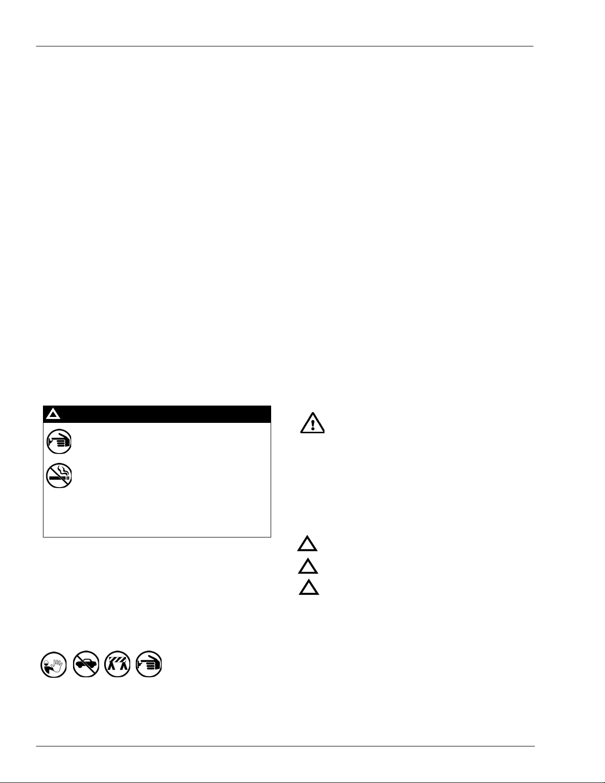
The EMERGENCY STOP, ALL STOP, and
PUMP STOP buttons at the cashier’s station
WILL NOT shut off electrical power to the
pump/dispenser. This means that even if you
activate these stops, fuel may continue to flow
uncontrolled.
You must use the TOTAL ELECTRICAL
SHUT-OFF in the case of an emergency and not
the console’s ALL STOP and PUMP STOP or
similar keys.
!
WARNING
!
Important Safety Information
Notes: 1) Save this Important Safety Information section
in a readily accessible location.
2) Although DEF is non-flammable, Diesel is
flammable. Therefore, for DEF cabinets that are
attached to Diesel dispensers, follow all the
notes in this section that pertain to flammable
fuels.
This section introduces the hazards and safety precautions
associated with installing, inspecting, maintaining or servicing
this product. Before performing any task on this product, read
this safety information and the applicable sections in this
manual, where additional hazards and safety precautions for
your task will be found. Fire, explosion, electrical shock or
pressure release could occur and cause death or serious injury,
if these safe service procedures are not followed.
Preliminary Precautions
You are wor king in a potentially dangerous environment of
flammable fuels, vapors, and high voltage or pressures. Only
trained or authorized individuals knowledgeable in the related
procedures should install, inspect, maintain or service this
equipment.
Emergency Total Electrical Shut-Off
The first and most important information you must know is how
to stop all fuel flow to the pump/dispenser and island. Loca te
the switch or circuit breakers that shut of f all power to all fueling
equipment, dispensing devices, and Submerged Turbine
Pumps (STPs).
Read the Manual
Read, understand and follow this manual and any other labels
or related materials supplied with this equipment. If you do not
understand a procedure, call a Gasboy Authorized Serv ice
Contractor or call the Gasboy Service Center at
1-800-444-5529. It is imperative to your safety and the sa fety of
others to understand the procedures before beginning work.
Follow the Regulations
Applicable information is available in National Fire Protection
Association (NFPA) 30A; Code for Motor Fuel Dispensing
Facilities and Repair Garages, NFPA 70; National Electrical
Code (NEC), Occupational Safety and Health Administration
(OSHA) regulations and federal, state, and local codes. All
these regulations must be followed. Failure to install, inspect,
maintain or service this equipment in accordance with these
codes, regulations and standards may lead to legal citations
with penalties or affect the safe use and operation of the
equipment.
Replacement Parts
Use only genuine Gasboy replacement parts and retrofit kits on
your pump/dispenser. Using parts other than genuine Gasboy
replacement parts could create a safety hazard and violate
local regulations.
Safety Symbols and Warning Words
This section provides important information about wa rning
symbols and boxes.
Alert Symbol
This safety alert symbol is used in this manual and on
warning labels to alert you to a precaution which must be
followed to prevent potential pe rsonal safety hazards. Obey
safety directives that follow this symbol to avoid possible injury
Total Electrical Shut-Off Before Access
Any procedure that requires access to electrical compo nents or
the electronics of the dispenser requires total electrical shut off
of that unit. Understand the function and location of this switch
or circuit breaker before inspecting, installing, maintaining, or
servicing Gasboy equipment.
Evacuating, Barricading and Shutting Off
Any procedure that requires access to the pump/dispenser or
STPs requires the following actions:
• An evacuation of all unauthorized persons and vehicles
from the work area
• Use of safety tape, cones or barricades at the affected
unit(s)
• A total electrical shu t-off of the affected unit(s)
Page 4 MDE-4512A Lamp Kit (M06227K00X) Installation Instructions for Atlas® 8700K/9100K and 8800K/9800K · June 2014
or death.
Signal Words
These signal words used in this manual and on warning labels
tell you the seriousness of particular safety hazards. The
precautions below must be followed to prevent death, injury or
damage to the equipment:
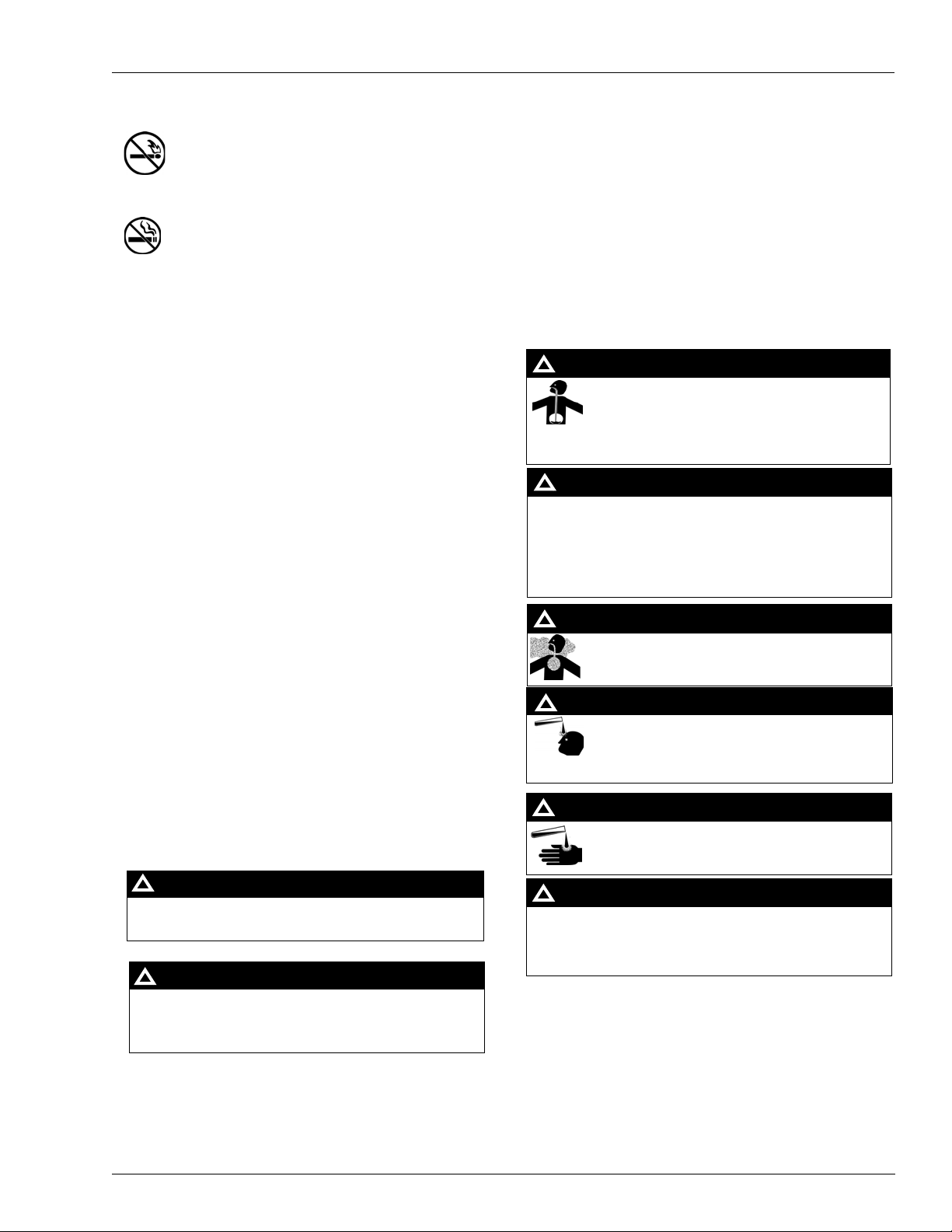
DANGER: Alerts you to a hazard or unsafe practice
!
which will result in death or serious injury.
WARNING: Alerts you to a hazard or unsafe practice
!
that could result in death or serious injury.
CAUTION with Alert symbol: Designates a hazard or
!
unsafe practice which may result in minor injury.
CAUTION without Alert symbol: Designates a hazard
or unsafe practice which may result in property or
equipment damage.
Working With Fuels and Electrical Energy
Prevent Explosions and Fires
Fuels and their vapors will explode or burn, if ignited. Spilled or
leaking fuels cause vapors. Even filling customer tanks wi ll
cause potentially dangerous vapors in the vicinity of the
dispenser or island.
DEF is non-flammable. Therefore, explosion and fire safety
warnings do not apply to DEF lines.
Page 5
Important Safety Information
The pump/dispenser contains a chemical known to the
State of California to cause cancer.
WARNING
!
The pump/dispenser contains a chemical known to the
State of California to ca use birth defects or other
reproductive harm.
WARNING
!
Gasoline/DEF ingested may cause
unconsciousness and burns to internal organs.
Do not induce vomiting. Keep airway open.
Oxygen may be needed at scene. Seek medical
advice immediately.
WARNING
!
WARNING
!
DEF generates ammonia gas at higher temperatures.
When opening enclosed panels, allow the unit to air out to
avoid breathing vapors.
If respiratory difficulties develop, move victim away from
source of exposure and into fresh air. If symptoms persist,
seek medical attention.
Gasoline/DEF spilled in eyes may cause burns to
eye tissue. Irrigate eyes with water for
approximately 15 minutes. Seek medical advice
immediately.
WARNING
!
WARNING
!
Gasoline inhaled may cause unconsciousness
and burns to lips, mouth and lungs. Keep airway
open. Seek medical advice immediately.
WARNING
!
Gasoline spilled on skin may cause burns.
Wash area thoroughly with clear water.
Seek medical advice immediately.
WARNING
!
DEF is mildly corrosive. Avoid contact with eyes, skin, and
clothing. Ensure that eyewash stations and safety s howers
are close to the work location. Seek medical advice
recommended treatment if DEF spills into eyes.
WARNING
!
No Open Fire
Open flames from matches, lighters, welding torches
or other sources can ignite fuels and their vapors.
No Sparks - No Smoking
Sparks from starting vehicles, starting or using power tools,
burning cigarettes, cigars or pipes can also ignite fuels and
their vapors. Static electricity, including an electrostatic charge
on your body, can cause a spark sufficient to ignite fuel vapors.
Every time you get out of a vehicle, touch the metal of your
vehicle, to discharge any electrostatic charge before you
approach the dispenser island.
Working Alone
It is highly recommended that someone who is capa ble of
rendering first aid be present during servicing. Familiarize
yourself with Cardiopulmonary Resuscitation (CP R) methods, if
you work with or around high voltages. This information is
available from the American Red Cross. Always advise the
station personnel about where you will be working, and caution
them not to activate power while you are working on the
equipment. Use the OSHA Lockout/Tagout procedures. If you
are not familiar with this requirement, refer to this information in
the service manual and OSHA documentation.
In an Emergency
Inform Emergency Personnel
Compile the following information and inform emergency
personnel:
• Location of accident (for example, address, front/back of
building, and so on)
• Nature of accident (for example, possible heart attack, run
over by car, burns, and so on)
• Age of victim (for example, baby, teenager, middle-ag e,
elderly)
• Whether or not victim has received first aid (for example,
stopped bleeding by pressure, and so on)
• Whether or not a victim has vomited (for example, if
swallowed or inhaled something, and so on)
Working With Electricity Safely
Ensure that you use safe and established practices in working
with electrical devices. Poorly wired devices may cause a fire,
explosion or electrical shock. Ensure that grounding
connections are properly made. Take care that sealing devices
and compounds are in place. Ensure that you do not pinch
wires when replacing covers. Follow OSHA Lockout/Tagout
requirements. Station employees and service contractors need
to understand and comply with this program completely to
ensure safety while the equipment is down.
Hazardous Materials
Some materials present inside electronic enclosures may
present a health hazard if not handled correctly. Ensure that
you clean hands after handling equipment. Do not place any
equipment in the mouth.
MDE-4512A Lamp Kit (M06227K00X) Installation Instructions for Atlas® 8700K/9100K and 8800K/9800K · June 2014 Page 5
IMPORTANT: Oxygen may be needed at sc ene if gasolin e has
been ingested or inhaled. Seek medical advice immediately.
Lockout/Tagout
Lockout/Tagout covers servicing and maintenance of machines
and equipment in which the unexpected energization or startup of the machine(s) or equipment or releas e of stored energy
could cause injury to employees or personnel. Lockout/Tagout
applies to all mechanical, hydraulic, chemical or other energy,
but does not cover electrical hazards. Subpart S of 29 CFR Part
1910 - Electrical Hazards, 29 CFR Part 1910.333 contains
specific Lockout/Tagout provision for electrical hazards.
Page 6

Before You BeginBefore You Begin
A properly grounded ESD (Electrostatic Discharge) wrist strap must be worn
while servicing any electronic devices or components. Failure to use electrostatic
precautions may damage electronic components and void warranty.
CAUTION
Failure to turn off the unit during the installation of the kit may cause injury or bodily harm
from electrical shock. Ensure that all power to the unit is switched off before opening the
door to the unit and during installation of the kit.
WARNING
Before You Begin
Installing the Lamp Kit (M06227K00X) involves AC wiring to the pump/dispenser.
Before you begin, review and ensure that all wiring and conduit requirements listed in
MDE-4331 Atlas
Fuel Systems Installation Manual are followed.
To prepare the site and pump/dispenser for installation, proceed as
1 Ensure that all power has been removed from the unit as listed in “Important Safety
Information” on page 4.
2 Ensure that the unit is barricaded to prevent customer access as listed in “Important Safety
Information” on page 4.
3 Match the parts received in the kit with “Parts List” on page 2, for the model pump/dispenser
to be retrofitted.
Preparing for Installation
To prepare for the installation, proceed as follows:
1 Unlock and remove the front panel.
follows:
2 Remove the two screws located over the tabs of the bezel assembly. Lift the bezel assembly
upward and out to remove.
Note: Save the screws for reassembly of the unit after installati
If retrofitting an electronic model (8800K or 9800K), loosen and remove the two screws
ocated on the left and right display panel brackets and pivot the display panels down.
l
Note: Save the screws for reassembly of the unit after installati
3 If the kit is replacing an existing fluorescent light kit, carefully remove the existing fluorescent
tubes, ballast, and lamp holders.
Page 6 MDE-4512A Lamp Kit (M06227K00X) Installation Instructions for Atlas® 8700K/9100K and 8800K/9800K · June 2014
on is complete.
on is complete.
Page 7

Installing Lamp Kit (M06227K00X)
DC OUT
(Red and Black
Wires)
AC IN (Black
and White
Wires)
LED Driver Mounting
Bracket (M13930A001)
LED Driver (M13929B001)
(i)
(ii)
Metric M5 X 8 Screw (M00417B020)
Lamp Mounting Bar
LED Driver (M13929B001)
To install the Lamp Kit, proceed as follows:
Installing LED Driver and LED Light Strips
To install the LED Driver (M13929B001) and LED Light Strips (M13924A001), proceed as
follows:
1 Locate the LED driver, LED Driver Mounting Bracket (M13930A001), and the two Metric
Hexagonal (KEPS) M4 X 0.7 Nuts (Q12885-05) supplied in the kit. Attach the LED driver to
the mounting bracket using the metric hexagonal (KEPS) M4 X 0. 7 n uts as show n in Figure 1 .
Figure 1: Attaching LED Driver to LED Driver Mounting Bracket
Installing Lamp Kit (M06227K00X)
If the kit is being installed into an electronic pump/dispenser (8800K/9800K), locate the LED
driver AC Power Extension Cable (M13928A001) and two Wire Nuts (K81105-02). Matching
the wire colors, attach the cable to AC IN wires (black a nd white) on the LED driver using the
two wire nuts.
2 Using the two Metric M5 X 8 Screws (M00417B020) from the kit, mount the LED
driver/bracket assembly on the middle of the back of the lamp mounting bar
. Position the
assembly so the black and white power wires extend from the right end after the assembly is
mounted.
Note: Figure 2 shows a mechanical register. Mounting of LED driver and the LED light strips
is the same for both mechanical and electronic register units.
Figure 2: Lamp Mounting Bar (Shown with LED Driver/Bracket Assembly Already
Mounted)
MDE-4512A Lamp Kit (M06227K00X) Installation Instructions for Atlas® 8700K/9100K and 8800K/9800K · June 2014 Page 7
Page 8

Installing Lamp Kit (M06227K00X)Installing Lamp Kit (M06227K00X)
(i)
(ii)
(iii)
Nylon Mounting
Buttons (Q13701-04)
3 Using the two Nylon Mounting Buttons (Q13701-04), mount the LED light strip on the front
side of the lamp mounting bracket, as shown in Figure 3 (LEDs on the lower side). The
mounting button must be inserted from the back side of the lamp mo
through the LED light strip using the mounting holes close to the J1/J2 connector. Holding the
LED strip, push the mounting button into place until it clicks and the strip is fastened securely.
Figure 3: Inserting Nylon Mounting Buttons
unting bracket, and goes
Page 8 MDE-4512A Lamp Kit (M06227K00X) Installation Instructions for Atlas® 8700K/9100K and 8800K/9800K · June 2014
Page 9

Installing Lamp Kit (M06227K00X)
(i)
(ii)
Black Tie-wraps (Q10178-10)
Lamp Mounting
Bracket
LED Strip
Black Tie-wrap (Q10178-10)
4 Using the two Tie-wraps [(Q10178-10) about 8 inches long] per side, secure the strip against
the lamp mounting bracket. Position the tie-wraps about a third of the way from the ends over
the mounting holes in the LED strip as shown in Figure 4. Wrap the tie-wrap around the lamp
mounting bracket and LED strip and pull the tie-wraps tight.
Figure 4: Positioning Tie-wraps
5 If mounting two LED light strips, repeat steps 3 on page 8 to 4 for the second strip on the
opposite side of the unit.
6 Connect the LED Driver Output Extension Cable [M13980A001 (red and black wires)] to the
red and black wires on the DC OUT end of the LED driver assembly using the two wire nuts.
Ensure to match the wire colors.
7 Connect the other end of the red wire to the closest LED strip J1 connector routing the wire
through the slot in the lamp mounting bracket and over the edge of the LED strip as shown in
Figure 5 on page 10.
MDE-4512A Lamp Kit (M06227K00X) Installation Instructions for Atlas® 8700K/9100K and 8800K/9800K · June 2014 Page 9
Page 10

Installing Lamp Kit (M06227K00X)Installing Lamp Kit (M06227K00X)
Wire Release
Slot in Lamp Mounting BracketLED Strip
J1 Connector
8 Insert the red wire into the V+ input and push the wire into the input firmly until it stops.
Note: If you need to remove the wire, press down on the wire
Figure 5: Inserting Red Wire into V+ Input
release and pull the wire out.
9 Connect the black wire to the back side of LED strip J2 connector, routing the wire through the
slot in the lamp mounting bracket and over the edge of the LED strip. Insert the end of the
black wire into the V- input.
10 Connect the front side LED strip to the back side LED strip using the LED Strip Interconnect
Cable [M13981A001 (blue wire)]. Insert one end of the wire into th e V- input of the J2
connector on the front side LED strip, routing it through the slots in the lamp mounting
brackets, and over the edge of the LED strips. Insert the other end into the V+ input of the J1
connector on the back side of the LED strip.
Figure 6: LED Strip Wiring - Tw o Strips
Page 10 MDE-4512A Lamp Kit (M06227K00X) Installation Instructions for Atlas® 8700K/9100K and 8800K/9800K · June 2014
Page 11

Installing Lamp Kit (M06227K00X)
Adhesive Cable
Mount (Q13558-04)
J1 Connector
Black Wire
11 If only one LED strip is being installed, the black wire from the LED driver connects to the
V- input on the J2 connect of the LED strip.
Figure 7: LED Strip Wiring - Single Strip
12 Using the Adhesive Cable Mounts (Q13558-04), secure the installed wiring up and out of the
way.
Figure 8: Securing the Wiring
For electronic models (8800K/9800K), connect the AC p ower extension cable P403 connector
to the J403 connector of the pump/dispenser main AC conduit assembly.
For mechanical models (8700K/9100K), connect the AC power wires (black and white) from
LED driver to the AC power from the reset assembly (units that have resets fitted for the
the
light option) or the Retrofit Conduit (021433) supplied with the kit. Secure wire connections
with wire nuts. For installing the retrofit conduit, refer to “Installing Retrofit Conduit
(Mechanical Models Only)” on page 12.
Installing the LED driver and LED light strip is now complete.
If installing the kit in an electronic unit, proceed to “Completing Installation” on page 13.
MDE-4512A Lamp Kit (M06227K00X) Installation Instructions for Atlas® 8700K/9100K and 8800K/9800K · June 2014 Page 11
Page 12

Installing Lamp Kit (M06227K00X)Installing Lamp Kit (M06227K00X)
Be very careful when bending and shaping the conduit assembly. The tubing is
very easily deformed and may kink if bent in too short a radius.
CAUTION
Union and Bushing
Cross Member
Tie-wrap
Conduit Assembly
Tie-wrap
Installing Retrofit Conduit (Mechanical Models Only)
To install the Retrofit Conduit (021433) in mechanical models, proceed as follows:
1 At the AC Junction Box (J-box), remove the bolts securing the J-box cover and remove the
cover.
Note: Save the bolts for reassembly of the unit after th
2 Locate the Conduit Assembly (021433), Bushing Assembly (K49827), and the Expansion
Union (N16289-20).
3 Mount the union to one end of the conduit assembly.
4 Mount the bushing assembly in an available opening in the J-box to accommodate the conduit
assembly.
5 Install the conduit assembly in the unit by placing the end with the mounted union into the unit
above the cross member and feeding down toward the J-box. The tubing must be carefully
bent and shaped to allow the union to fit into the bushing mounted to the J-box.
e installation is complete.
Figure 9: Installing Conduit Assembly
Page 12 MDE-4512A Lamp Kit (M06227K00X) Installation Instructions for Atlas® 8700K/9100K and 8800K/9800K · June 2014
Page 13

6 Connect the union to the bushing on the J-box.
Avoid looking directly at the LEDs when lit. Ensure bezels are in place with brand
panel graphics installed before lighting LED strips.
WARNING
7 At the top of the conduit, bend and shape the conduit to accommodate connecting to the black
and white wires extending from the AC IN side of the LED driver assembly.
8 Using the tie-wraps, secure the conduit to the unit to prevent movement. For typical tie-wrap
placement, see Figure 9 on page 12.
9 Once the wiring in the J-box is complete, remount the J-box cover and secure with the bolts
saved.
Installing the retrofit conduit (mechanical models) is now complete.
Completing Installation
To complete the installation, proceed as follows:
1 Complete the wiring to the LIGHT FEED and LIGHT NEUTRAL in the AC J-box. For more
information, refer to MDE-4331 Atlas
diagrams.
Completing Installation
Fuel Systems Installation Manual and Atlas wiring
2 On the electronic model units, secure the display panel in the upright position.
3 Attach the bezel. Ensure the bezel is seated properly to ensure a watertight seal.
4 Attach and lock the front panel.
5 Turn on all the circuit breakers supplying power to the unit.
Installing the Lamp Kit in Atlas pumps/dispensers 8700K/9100K (mechanical) and
8800K/9800K (electronic) is now complete.
MDE-4512A Lamp Kit (M06227K00X) Installation Instructions for Atlas® 8700K/9100K and 8800K/9800K · June 2014 Page 13
Page 14

Atlas® and Gasboy® are registered trademarks of Gasboy International. Gilbarco® is a registered trademark of Gilbarco Inc. GOLDSM is a
service mark of Gilbarco Inc. NEC® and NFPA 70® are registered trademarks of the National Fire Protection Associat ion. Phillips® is a
register ed trademark of Phillips Screw Company.
© 2014 GASBOY
7300 West Friendly Avenue · Post Office Box 22087
Greensboro, North Carolina 27420
Phone (336) 547-5000 · http://www.gasboy.com. Printed in the U.S.A..
MDE-4512A Lamp Kit (M06227K00X) Installation Instru ctions for Atla s® 8700K/91 00K and 88 00K/9800K · Jun e 2014
 Loading...