

Page 1
HIGH HOSE RETRIEVER KIT INSTALLATION INSTRUCTIONS
FOR MODELS 8700E/8800E/9100A/7500A
This instruction sheet c overs the installation of the Models 8700E, 8800E, 9100A, 7500A High Hose Retriever Kit
(Gasboy P/N 032675). You should have received the following:
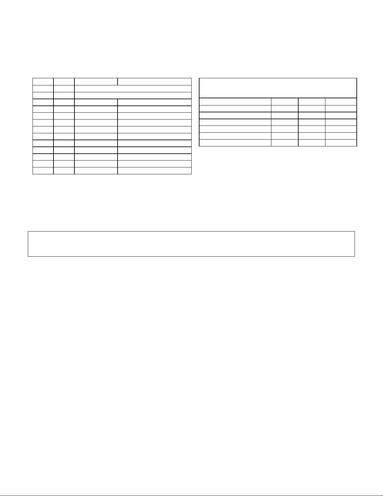
Item Qty. P/N Description
1 1 SEE REEL & CLAMP MATRIX
2 1 SEE REEL & CLAMP MATRIX
3 1 063818 Support Bar Assy.
4 1 017930 Caplug
5 3 051956 Bolt (5/16-18 x 2) SS
6 1 051957 Bolt (5/16-18 x 2-1/2) SS
8 4 068079 Washer (5/16) SS
9 4 068874 Lock Washer (5/16) SS
11 1 063208 Spacer
12 1 047219 Plug Button (7/8)
13 1 013250 Anchor (5/16)
N/A 1 032621 Instruction Sheet
N/A 1 035282 Warning Sheet
The kits listed below consist of one reel and one clamp
unless noted otherwise.
Hose Type Kit P/N Reel Clamp
5/8”, ¾“ HW/SW 032666 030804 020714
1” SW 032667 030805 020712
1” HW (STD 1-7/16” OD) 032668 030805 020718
1” HW (1-3/8” OD) 032669 030805 020719
GY PREM COAX V.R. 032671 030804 026732
1-1/4” SW 032670 030805 020717
REEL & CLAMP MATRIX
In addition to the standard tools and supplies required f or dispenser ins tallations, you will also need a 5/8” diameter
masonry drill bit
Important: Read all instructions before beginning installation. Also, read and follow all precautions regarding
remote dispensers and pumps on the Warnings and Safeguards sheet, 035282, included in this kit.
WARNING
This is a hazardous location and thus prohibits the use of spark and/or heat producing tools. The use of a
pneumatic tool operating at a low speed is recommended for drilling operation performed in Step 4.
Mounting Hose Retriever
1. Assemble clamp and reel assy. (items 1 and 2) to support post (item 3) with hardware items 5, 9, and 8.
2. Install cap-plug (item 4) to top of support post (item 3).
3. Install reel and support post assem bly to side of dispensing unit with items 6, 9, 8, and 11 and leave loose.
Item 11 mounts between post and side panel.
4. Mak ing sure that support pos t is plumb, m ark and drill a 5/8” DIA. X 1-3/4” deep hole in island. Install anchor
(item 13) into island surface. Fasten support bar to island using hardware items 5, 9, and 8.
5. Tighten all hardware from Step 3. Plug hole in support post with item 12.
Mounting Hose to Retriever/Clamp Assy.
6. Assem ble clam p to hose and position so that hos e does not touch ground when nozzle is hung in nozzle boot.
Pull out hose and check operation of the retriever and lay of hose.
032621 Rev. 1212 Page 1
Page 2
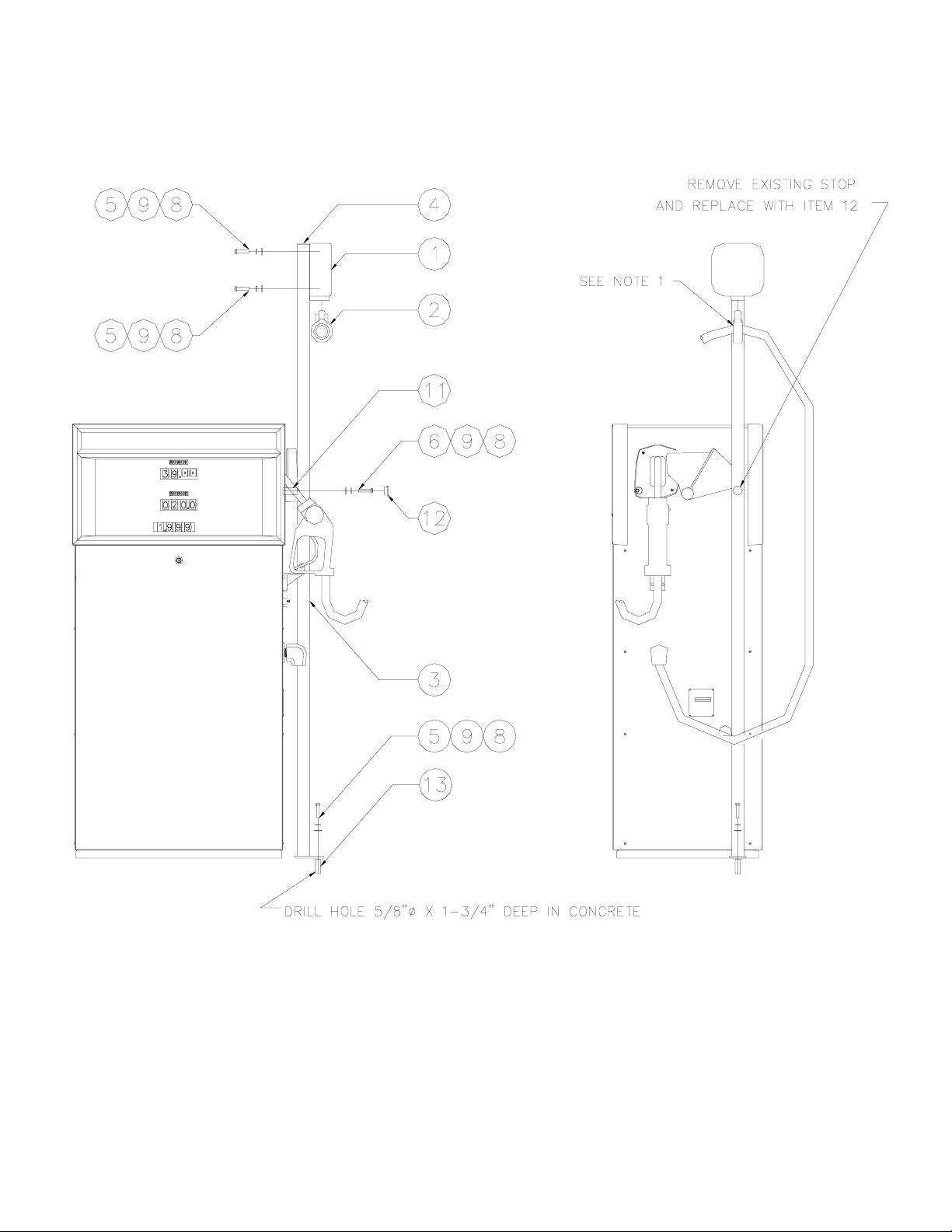
HIGH HOSE RETRIEVER OVERVIEW
NOTE 1: Clamp should be positioned so that hose does not touch the ground when nozzle is hung in nozzle boot.
032621 Rev. 1212 Page 2
 Loading...