

Page 1

Series 580
Installation/Operation/Parts
Manual
MDE-4766
(formerly C35393)
Page 2

Computer Programs and Documentation
Federal Communications Commission (FCC) Warning
All Gasboy computer programs (including software on diskettes and within memory chips) and documentation are copyrighted by, and shall remain the property of, Gasboy. Such
computer programs and documents may also contain trade secret information. The duplication, disclosure, modification, or unauthorized use of computer programs or
documentation is strictly prohibited, unless otherwise licensed by Gasboy.
This equipment has been tested and found to comply with the limits for a Class A digital device pursuant to Part 15 of the FCC Rules. These limits are designed to provide
reasonable protection against harmful interference when the equipment is operated in a commercial environment. This equipment generates, uses, and can radiate radio frequency
energy, and if not installed and used in accordance with the instruction manual, may cause harmful interference to radio communications. Operation of this equipment in a
residential area is likely to cause harmful interference in which case the user will be required to correct the interference at his own expense. Changes or modifications not expressly
approved by the manufacturer could void the user’s authority to operate this equipment.
Approvals
Gasboy, Greensboro, is an ISO 9001:2000 registered facility.
Underwriters Laboratories (UL):
UL File# Products listed with UL
MH4314
MH6418
MH7404
MH10581 Key con t r o l u n i t , M o d e l G K E - B S e r i e s
All dispensers and self-contained pumping
units
Power operated Transfer Pump Models 25,
25C, 26, 27, 28, 72, 72S, 72SP , 72X, 73 and
1820
Hand operated Transfer Pump Models 1230
Series, 1243 Series, 1520 and 1720 Series
Card reader terminals, Models 1000, 1000P
Site controller, Model 2000S CFN Series
Data entry terminals, Model TPK-900 Series
Fuel Point Reader System
New York City Fire Department (NYFD):
NYFD C of A # Product
4823 9100A, 9140A, 9152A, 9153A,
4997 9822A, 9823A
5046 9100Q, 9140Q, 9152Q, 9153Q,
5087 8753K, 8853K, 9153K, 9853K
5091 8752K, 9152K
5129 9122K, 9123K, 9822K, 9823K
9800A, 9840A, 9850A, 9852A,
9853A, 9140
9800Q, 9840Q, 9852Q, 9853Q
(restricted to diesel and nonretail gasoline sales)
National Conference of Weights and Measures (NCWM) - Certificate of Compliance (CoC):
Gasboy pumps and dispensers are evaluated by NCWM under the National Type Evaluation Program (NTEP). NCWM has issued the following CoC:
CoC# Product Model # CoC# Product Model # CoC# Product Model #
95-179 Dispenser
95-136 Dispenser 9800 Series 91-057 Controller
9100 Retail Series, 8700
Series, 9700 Series
91-019 Dispenser
9100 Commercial
Series
1000 Series FMS,
2000S-CFN Series
California Air Resources Board (CARB):
Executive Order # Product
G-70-52-AM Balance Vapor Recovery
G-70-150-AE VaporVac
05-002 Atlas
8700K, 8800K,
9100K, 9200K, 9800K
Patents
Gasboy products are manufactured or sold under one or more of the following US patents:
Dispensers
5,257,720
Point of Sale/Back Office Equipment
D335,673
Trademarks
Non-registered trademarks
Atlas™
Consola™
Infinity™
Registered trademarks
ASTRA
Fuel Point
Gasboy
Keytrol
Slimline
Additional US and foreign patents pending.
®
®
®
®
®
Additional US and foreign trademarks pending.
Other brand or product names shown may be
trademarks or registered trademarks of their
respective holders.
This document is subject to change without notice.
E-mail: literature@gasboy.com · Internet: http://www.gasboy.com
© 2009 GASBOY. All Rights Reserved.
Page 3

Table of Contents
1 – Introduction 1
Purpose. . . . . . . . . . . . . . . . . . . . . . . . . . . . . . . . . . . . . . . . . . . . . . . . . . . . . . . . . . . . . . . . . . . . . . . . . .1
Intended Users . . . . . . . . . . . . . . . . . . . . . . . . . . . . . . . . . . . . . . . . . . . . . . . . . . . . . . . . . . . . . . . . . . . .1
Overview . . . . . . . . . . . . . . . . . . . . . . . . . . . . . . . . . . . . . . . . . . . . . . . . . . . . . . . . . . . . . . . . . . . . . . . . .1
Abbreviations and Acronyms. . . . . . . . . . . . . . . . . . . . . . . . . . . . . . . . . . . . . . . . . . . . . . . . . . . . . . . . . .2
Warranty . . . . . . . . . . . . . . . . . . . . . . . . . . . . . . . . . . . . . . . . . . . . . . . . . . . . . . . . . . . . . . . . . . . . . . . . .2
2 – Important Safety Information 3
3 – Installation 7
Before You Begin . . . . . . . . . . . . . . . . . . . . . . . . . . . . . . . . . . . . . . . . . . . . . . . . . . . . . . . . . . . . . . . . . .7
Installation Precautions . . . . . . . . . . . . . . . . . . . . . . . . . . . . . . . . . . . . . . . . . . . . . . . . . . . . . . . . . . . . . .7
Foundation. . . . . . . . . . . . . . . . . . . . . . . . . . . . . . . . . . . . . . . . . . . . . . . . . . . . . . . . . . . . . . . . . . . . . . . .8
Suction Pump . . . . . . . . . . . . . . . . . . . . . . . . . . . . . . . . . . . . . . . . . . . . . . . . . . . . . . . . . . . . . . . . . . . . .8
Typical Installation Layout . . . . . . . . . . . . . . . . . . . . . . . . . . . . . . . . . . . . . . . . . . . . . . . . . . . . . . . . . . . .9
Supply Line . . . . . . . . . . . . . . . . . . . . . . . . . . . . . . . . . . . . . . . . . . . . . . . . . . . . . . . . . . . . . . . . . . . . . . .9
Dimensions . . . . . . . . . . . . . . . . . . . . . . . . . . . . . . . . . . . . . . . . . . . . . . . . . . . . . . . . . . . . . . . . . . . . . .11
Base Layout. . . . . . . . . . . . . . . . . . . . . . . . . . . . . . . . . . . . . . . . . . . . . . . . . . . . . . . . . . . . . . . . . . . . . .12
4 – Wiring 13
Wiring Precautions . . . . . . . . . . . . . . . . . . . . . . . . . . . . . . . . . . . . . . . . . . . . . . . . . . . . . . . . . . . . . . . .13
Grounding . . . . . . . . . . . . . . . . . . . . . . . . . . . . . . . . . . . . . . . . . . . . . . . . . . . . . . . . . . . . . . . . . . . . . . .14
Circuit Breakers. . . . . . . . . . . . . . . . . . . . . . . . . . . . . . . . . . . . . . . . . . . . . . . . . . . . . . . . . . . . . . . . . . .14
Pump Motor. . . . . . . . . . . . . . . . . . . . . . . . . . . . . . . . . . . . . . . . . . . . . . . . . . . . . . . . . . . . . . . . . . . . . .14
Pulsers and Pulser Wiring . . . . . . . . . . . . . . . . . . . . . . . . . . . . . . . . . . . . . . . . . . . . . . . . . . . . . . . . . . .15
Conduit . . . . . . . . . . . . . . . . . . . . . . . . . . . . . . . . . . . . . . . . . . . . . . . . . . . . . . . . . . . . . . . . . . . . . . . . .15
Wiring Diagram . . . . . . . . . . . . . . . . . . . . . . . . . . . . . . . . . . . . . . . . . . . . . . . . . . . . . . . . . . . . . . . . . . .17
5 – Startup and Operation 19
Pre-startup Checklist. . . . . . . . . . . . . . . . . . . . . . . . . . . . . . . . . . . . . . . . . . . . . . . . . . . . . . . . . . . . . . .19
Startup and Pump Operation. . . . . . . . . . . . . . . . . . . . . . . . . . . . . . . . . . . . . . . . . . . . . . . . . . . . . . . . .19
Post Startup Tests. . . . . . . . . . . . . . . . . . . . . . . . . . . . . . . . . . . . . . . . . . . . . . . . . . . . . . . . . . . . . . . . .20
Voltage. . . . . . . . . . . . . . . . . . . . . . . . . . . . . . . . . . . . . . . . . . . . . . . . . . .20
Tightness . . . . . . . . . . . . . . . . . . . . . . . . . . . . . . . . . . . . . . . . . . . . . . . . .20
Meter Calibration . . . . . . . . . . . . . . . . . . . . . . . . . . . . . . . . . . . . . . . . . . .20
Strainer Cleaning . . . . . . . . . . . . . . . . . . . . . . . . . . . . . . . . . . . . . . . . . . .21
Belt. . . . . . . . . . . . . . . . . . . . . . . . . . . . . . . . . . . . . . . . . . . . . . . . . . . . . .21
Reconfiguration of Pump Pulley for Hand Crank Operation . . . . . . . . . . . . . . . . . . . . . . . . . . . . . . . . .21
6 – Maintenance and Troubleshooting 23
When Your Pump Needs Service . . . . . . . . . . . . . . . . . . . . . . . . . . . . . . . . . . . . . . . . . . . . . . . . . . . . .23
Maintaining Trouble-free Operation. . . . . . . . . . . . . . . . . . . . . . . . . . . . . . . . . . . . . . . . . . . . . . . . . . . .23
Troubleshooting. . . . . . . . . . . . . . . . . . . . . . . . . . . . . . . . . . . . . . . . . . . . . . . . . . . . . . . . . . . . . . . . . . .25
Pump Does Not Start . . . . . . . . . . . . . . . . . . . . . . . . . . . . . . . . . . . . . . . .25
Pump Hums but Does Not Start. . . . . . . . . . . . . . . . . . . . . . . . . . . . . . . .25
MDE-4766 Series 580 Installation/Operation/Parts Manual · April 2009 Page i
Page 4

Pump Runs but Does Not Prime or Deliver Product . . . . . . . . . . . . . . . . 26
Pump Delivers Product but Does Not Register. . . . . . . . . . . . . . . . . . . . 26
Pump Delivery is Slow . . . . . . . . . . . . . . . . . . . . . . . . . . . . . . . . . . . . . . 26
Pump Loses Prime . . . . . . . . . . . . . . . . . . . . . . . . . . . . . . . . . . . . . . . . . 26
Inaccurate Delivery . . . . . . . . . . . . . . . . . . . . . . . . . . . . . . . . . . . . . . . . . 27
Pump Delivers Product When not Turned On. . . . . . . . . . . . . . . . . . . . . 27
Meter Register Disassembly. . . . . . . . . . . . . . . . . . . . . . . . . . . . . . . . . . . . . . . . . . . . . . . . . . . . . . . . . 27
4860 4 - Wheel Register Service . . . . . . . . . . . . . . . . . . . . . . . . . . . . . . 27
7 – Parts List 29
General. . . . . . . . . . . . . . . . . . . . . . . . . . . . . . . . . . . . . . . . . . . . . . . . . . . . . . . . . . . . . . . . . . . . . . . . . 29
582/583 Front View . . . . . . . . . . . . . . . . . . . . . . . . . . . . . . . . . . . . . . . . . . . . . . . . . . . . . . . . . . . . . . . 30
582/583 Side View . . . . . . . . . . . . . . . . . . . . . . . . . . . . . . . . . . . . . . . . . . . . . . . . . . . . . . . . . . . . . . . . 31
582/583 Chassis. . . . . . . . . . . . . . . . . . . . . . . . . . . . . . . . . . . . . . . . . . . . . . . . . . . . . . . . . . . . . . . . . . 32
582/583 Motor . . . . . . . . . . . . . . . . . . . . . . . . . . . . . . . . . . . . . . . . . . . . . . . . . . . . . . . . . . . . . . . . . . . 34
582/583 Pump . . . . . . . . . . . . . . . . . . . . . . . . . . . . . . . . . . . . . . . . . . . . . . . . . . . . . . . . . . . . . . . . . . . 36
Pumping Unit Breakdown. . . . . . . . . . . . . . . . . . . . . . . . . . . . . . . . . . . . . . . . . . . . . . . . . . . . . . . . . . . 37
Model M04920B003 - Pumping Unit Parts List . . . . . . . . . . . . . . . . . . . . 38
582/583 Piping . . . . . . . . . . . . . . . . . . . . . . . . . . . . . . . . . . . . . . . . . . . . . . . . . . . . . . . . . . . . . . . . . . . 39
023070 Pipe Assembly . . . . . . . . . . . . . . . . . . . . . . . . . . . . . . . . . . . . . . 40
023079 Pipe W/Filter Assembly . . . . . . . . . . . . . . . . . . . . . . . . . . . . . . . 40
582/583 Pulser . . . . . . . . . . . . . . . . . . . . . . . . . . . . . . . . . . . . . . . . . . . . . . . . . . . . . . . . . . . . . . . . . . . 41
Hand Crank Assembly . . . . . . . . . . . . . . . . . . . . . . . . . . . . . . . . . . . . . . . . . . . . . . . . . . . . . . . . . . . . . 42
Accessories and Field Kits . . . . . . . . . . . . . . . . . . . . . . . . . . . . . . . . . . . . . . . . . . . . . . . . . . . . . . . . . . 43
External Low Flow Filter Kits. . . . . . . . . . . . . . . . . . . . . . . . . . . . . . . . . . 43
External High Flow Filter Kits . . . . . . . . . . . . . . . . . . . . . . . . . . . . . . . . . 43
Replacement Elements (For both 582 and 583 Models). . . . . . . . . . . . . 43
Pulser Kit. . . . . . . . . . . . . . . . . . . . . . . . . . . . . . . . . . . . . . . . . . . . . . . . . 43
Pumping Unit Kits . . . . . . . . . . . . . . . . . . . . . . . . . . . . . . . . . . . . . . . . . . 44
Index Index-1
Page ii MDE-4766 Series 580 Installation/Operation/Parts Manual · April 2009
Page 5

Purpose Introduction
1 – Introduction
Purpose
The Gasboy® Series 580 Installation/Operation/Parts Manual is provided to assist the installer
in installing and operating the unit. This manual should be supplied to the electrician prior to
the installation of conduit and wiring to ensure that the unit is installed properly. Faulty
installations are the major cause of unit malfunctions. This unit must be installed and operated
as described in the manual to ensure reliable operation. Ensure that you leave this manual with
the pump owner when the installation is complete, as the manual contains unit operating
instructions.
Note: Customers and installers who have questions pertaining to installation should contact
their Gasboy distributor.
Intended Users
This manual in intended for those responsible for the installation of the 580 unit, such as
installers and electricians.
Overview
The Gasboy 580 Series dispensers are heavy-duty suction pumps designed for the needs of
local and state governments, industrial, commercial, and private fleet operations. Important
information regarding 580 Series dispenser is provided below:
• Dimensions: Base 13-31/32-inch (35 cm) x 18-1/16-inch (46 cm), Height 40-1/8-inch
(102 cm).
• Construction: All panels are galvanized steel and painted with a two-part urethane paint
for rust resistance.
• Cabinet Colors: Painted black with red front door.
• Motor: Model 582 - 1/2 HP continuous duty, dual voltage/dual frequency, 115/230 VAC,
• Pump: A durable rotary vane pump with carbon blades is utilized to produce suction
power. Air elimination achieved through a patented static device using a vortex effect.
• Inlet Control Valve: The valve i s provided with the pump and is installed in the upstream
of the pump strainer.
• Register: 4-wheel push-button reset, 7-digit master totalizer, in US gallons or liters.
50/60 Hz
Model 583 - 3/4 HP continuous duty, dual voltage/dual frequency, 115/230 VAC,
50/60 Hz
MDE-4766 Series 580 Installation/Operation/Parts Manual · April 2009 Page 1
Page 6

Introduction Abbreviations and Acronyms
• Meter: Nutating disk phenolic measuring chamber in aluminum die-cast housing,
adjustable calibration
±.5% at full flow.
• Display: Single-sided
• Dial Face: Black with silver stripes highlighting register readings.
• Hose: 582 - 3/4-inch (2 cm) x 12 feet (3.6 m); 583 - 1-inch (2.5 cm) x 12 feet (3.6 m)
• Suction Connection: 1-1/2-inch NPT union provided.
• Delivery Rate: Model 582 up to 15 GPM/57 LPM. Model 583 up to 22 GPM/83 LPM.
Delivery rates are maximum test rates. Actual rates will vary depending upon installation
conditions, product dispensed, and added accessories.
• Nozzle: Must be purchased separately. Automatic nozzles available. Nozzle boot and
®
hook are designed for use with a UL
-listed interchangeable automatic service-station-
type nozzle.
Optional accessories include internal filter adapter, external filter kits, stainless steel cabinet,
manual hand crank, 50 Hz version, 380 V/50 Hz motor, 1:1 or 10:1 pulser, and liter
registration.
Abbreviations and Acronyms
Term Description
CARB California Air Resources Board
CoC Certificate of Compliance
FCC Federal Communications Commission
NCWM National Conference of Weights and Measures
NYFD New York City Fire Department
PC Personal Computer
Warranty
For information on warranty, refer to MDE-4255 Gasboy’s Warranty Policy Statement. If you
have any warranty-related questions, contact Gasboy’s Warranty Department at its
Greensboro location.
Page 2 MDE-4766 Series 580 Installation/Operation/Parts Manual · April 2009
Page 7
2 – Important Safety Information
Important Safety Information
This section introduces the hazards and safety precautions
associated with installing, inspecting, maintaining or servicing
this product. Before performing any task on this product, read
this safety information and the applicable sections in this
manual, where additional hazards and safety precautions for
your task will be found. Fire, explosion, electrical shock or
pressure release could occur and cause death or serious
injury, if these safe service procedures are not followed.
Preliminary Precautions
You are working in a potentially dangerous environment of
flammable fuels, vapors, and high voltage or pressures. Only
trained or authorized individuals knowledgeable in the related
procedures should install, inspect, maintain or service this
equipment.
Emergency Total Electrical Shut-Off
The first and most important information you must know is
how to stop all fuel flow to the pump/dispenser and island.
Locate the switch or circuit breakers that shut off all power to
all fueling equipment, dispensing devices, and Submerged
Turbine Pumps (STPs).
!
WARNING
!
The EMERGENCY STOP, ALL STOP, and
PUMP STOP buttons at the cashier’s station
WILL NOT shut off electrical po wer to the p ump/
dispenser. This means that even if you activate
these stops, fuel may continue to flow
uncontrolled.
Read the Manual
Read, understand and follow this manual and any other
labels or related materials supplied with this equipment. If you
do not understand a procedure, call a Gasboy Authorized
Service Contractor or call the Gasboy Service Center at 1800-444-5529. It is imperative to your safety and the safety of
others to understand the procedures before beginning work.
Follow the Regulations
Applicable information is available in National Fire Protection
Association (NFPA) 30A; Code for Motor Fuel Dispensing
Facilities and Repair Garages, NFPA 70; National Electrical
Code (NEC), Occupational Safety and Hazard Association
(OSHA) regulations and federal, state, and local codes. All
these regulations must be followed. Failure to install, inspect,
maintain or service this equipment in accordance with these
codes, regulations and standards may lead to legal citations
with penalties or affect the safe use and operation of the
equipment.
Replacement Parts
Use only genuine Gasboy replacement parts and retrofit kits
on your pump/dispenser. Using parts other than genuine
Gasboy replacement parts could create a safety hazard and
violate local regulations.
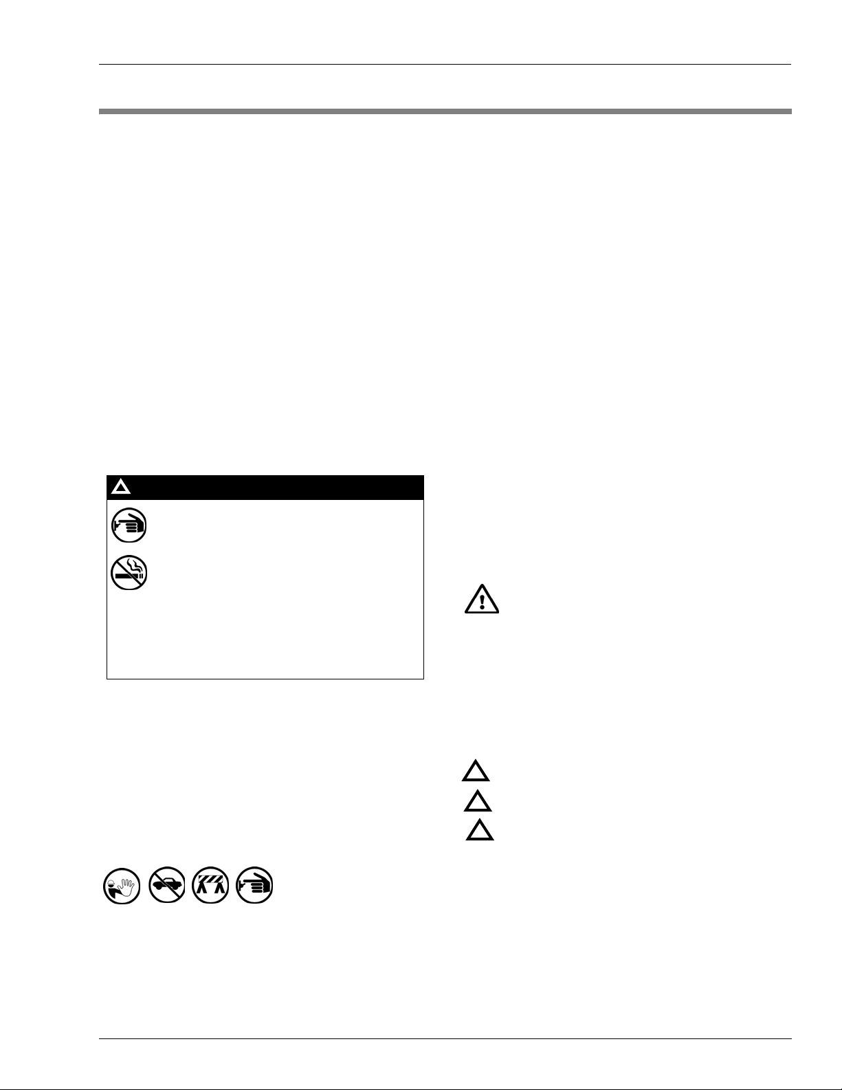
Safety Symbols and Warning Words
This section provides important information about warning
symbols and boxes.
Alert Symbol
You must use the TOTAL ELECTRICAL SHUTOFF in the case of an emergency and not the
console’s ALL STOP and PUMP STOP or
similar keys.
Total Electrical Shut-Off Before Access
Any procedure that requires access to electrical components
or the electronics of the dispenser requires total electrical
shut off of that unit. Understand the function and location of
this switch or circuit breaker before inspecting, installing,
maintaining, or servicing Gasboy equipment.
Evacuating, Barricading and Shutting Off
Any procedure that requires access to the pump/dispenser or
STPs requires the following actions:
• An evacuation of all unauthorized persons and vehicles
from the work area
• Use of safety tape, cones or barricades at the affected
unit (s)
• A total electrical shut-off of the affected unit (s)
This safety alert symbol is used in this manual and
on warning labels to alert you to a precaution which must be
followed to prevent potential personal safety hazards. Obey
safety directives that follow this symbol to avoid possible
injury or death.
Signal Words
These signal words used in this manual and on warning
labels tell you the seriousness of particular safety hazards.
The precautions below must be followed to prevent death,
injury or damage to the equipment:
DANGER: Alerts you to a hazard or unsafe practice
!
which will result in death or serious injury.
WARNING: Alerts you to a hazard or unsafe practice
!
that could result in death or serious injury.
CAUTION with Alert symbol: Designates a hazard or
!
unsafe practice which may result in minor injury.
CAUTION without Alert symbol: Designates a hazard
or unsafe practice which may result in property or
equipment damage
Working With Fuels and Electrical Energy
Prevent Explosions and Fires
Fuels and their vapors will explode or burn, if ignited. Spilled
or leaking fuels cause vapors. Even filling customer tanks will
cause potentially dangerous vapors in the vicinity of the
dispenser or island.
MDE-4766 Series 580 Installation/Operation/Parts Manual · April 2009 Page 3
Page 8
Important Safety Information
No Open Fire
Open flames from matches, lighters, welding torches
or other sources can ignite fuels and their vapors.
No Sparks - No Smoking
Sparks from starting vehicles, starting or using power tools,
burning cigarettes, cigars or pipes can also ignite fuels and
their vapors. Static electricity, including an electrostatic
charge on your body, can cause a spark sufficient to ignite
fuel vapors. Every time you get out of a vehicle, touch the
metal of your vehicle, to discharge any ele c tro static charge
before you approach the dispenser island.
Working Alone
It is highly recommended that someone who is capable of
rendering first aid be present during servicing. Familiarize
yourself with Cardiopulmonary Resuscitation (CPR) methods,
if you work with or around high voltages. This information is
available from the American Red Cross. Always advise the
station personnel about where you will be working, and
caution them not to activate power while you are working on
the equipment. Use the OSHA Lockout/ Tagout procedures. If
you are not familiar with this requirement, refer to this
information in the service manual and OSHA documentation.
Working With Electricity Safely
Ensure that you use safe and established practices in working
with electrical devices. Poorly wired devices may cause a fire,
explosion or electrical shock. Ensure that grounding
connections are properly made. Take care that sealing
devices and compounds are in place. Ensure that you do not
pinch wires when replacing covers. Follow OSHA Lockout/
Tagout requirements. Station employees and service
contractors need to understand and comply with this program
completely to ensure safety while the equipment is down.
In an Emergency
Inform Emergency Personnel
Compile the following information and inform emergency
personnel:
• Location of accident (for example, address, front/back of
building, and so on)
• Nature of accident (for example, possible heart attack, run
over by car, burns, and so on)
• Age of victim (for example, baby, teenager, middle-age,
elderly)
• Whether or not victim has received first aid (for example,
stopped bleeding by pressure, and so on)
• Whether or not a victim has vomited (for example, if
swallowed or inhaled something, and so on)
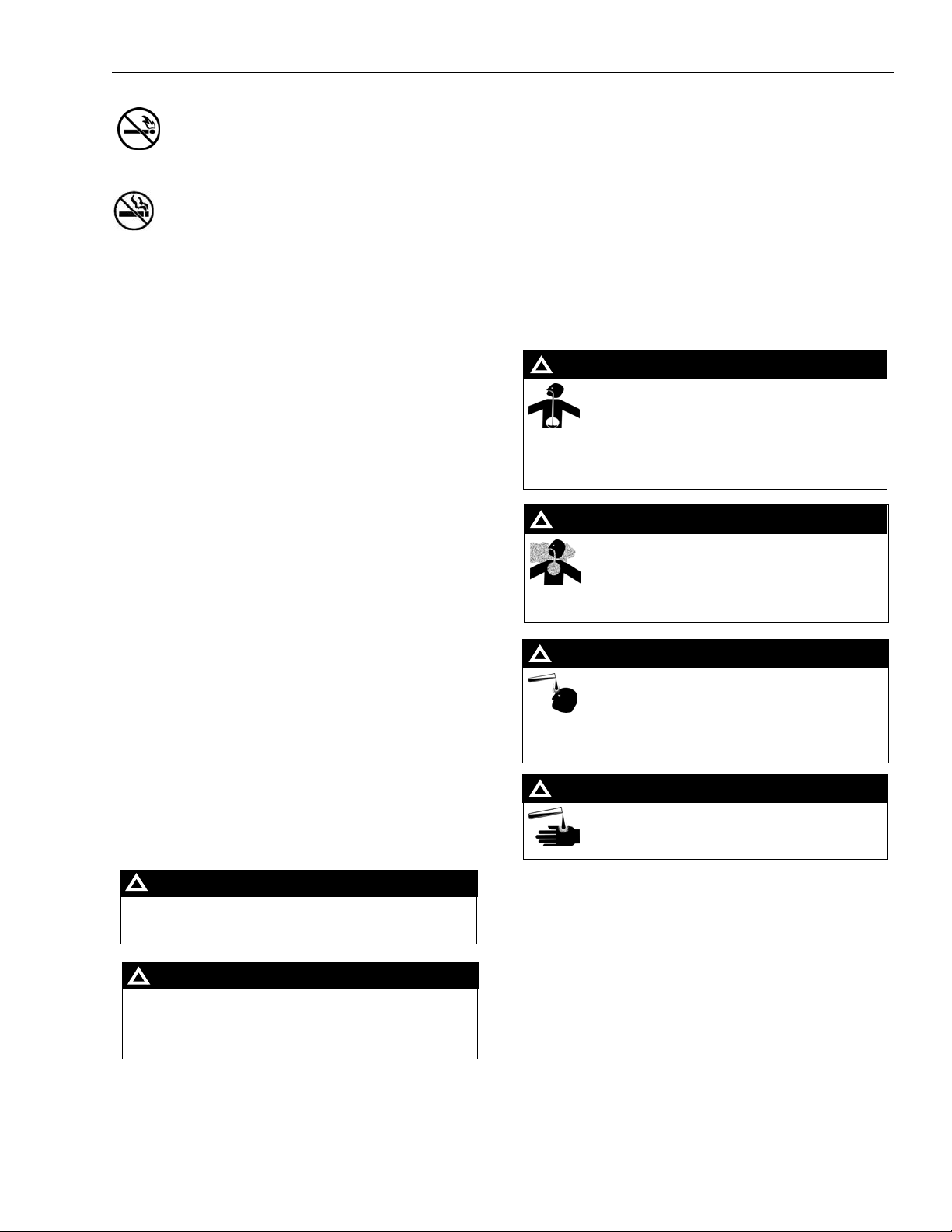
WARNING
!
Gasoline ingested may cause unconsciousness
and burns to internal organs.
Do not induce vomiting.
Keep airway open.
Oxygen may be needed at scene.
Seek medical advice immediately.
WARNING
!
Gasoline inhaled may cause unconsciousness
and burns to lips, mouth and lungs.
Keep airway open.
Seek medical advice immediately.
WARNING
!
Gasoline spilled in eyes may cause burns to eye
tissue.
Irrigate eyes with water for approximately 15
minutes.
Seek medical advice immediately.
Hazardous Materials
WARNING
Some materials present inside electronic enclosures may
present a health hazard if not handled correctly. Ensure that
you clean hands after handling equipment. Do not place any
equipment in the mouth.
!
WARNING
The pump/dispenser contains a chemical known to the
State of California to cause cancer.
!
Gasoline spilled on skin may cause burns.
Wash area thoroughly with clear water.
Seek medical advice immediately.
IMPORTANT: Oxygen may be needed at scene if gasoline
has been ingested or inhaled. Seek medical advice
immediately.
Lockout/Tagout
WARNING
!
Lockout/Tagout covers servicing and maintenance of
machines and equipment in which the unexpected
The pump/dispenser contains a chemical known to the
State of California to cause birth defects or other
reproductive harm.
energization or start-up of the machine(s) or equipment or
release of stored energy could cause injury to employees or
personnel. Lockout/Tagout applies to all mechanical,
hydraulic, chemical or other energy, but does not cover
electrical hazards. Subpart S of 29 CFR Part 1910 - Electrical
Hazards, 29 CFR Part 1910.333 contains specific Lockout/
Tagout provision for electrical hazards.
Page 4 MDE-4766 Series 580 Installation/Operation/Parts Manual · April 2009
Page 9
Hazards and Actions
Important Safety Information
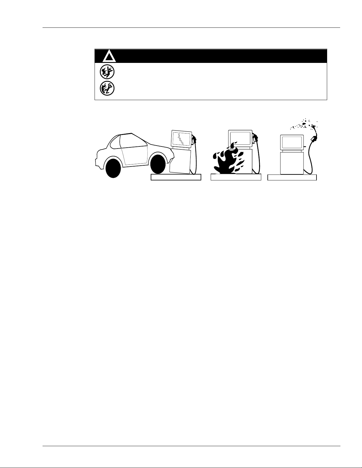
!
WARNING
Spilled fuels, accidents involving pump s/dispensers, or uncontrolled fuel flow create a
serious hazard.
Fire or explosion may result, causing serious injury or death.
Follow established emergency procedures.
The following actions are recommended regarding these hazards:
Collision of a Vehicle with Unit Fire at Island Fuel Spill
• Do not go near a fuel spill or allow anyone else in the area.
• Use station EMERGENCY CUTOFF immediately. Turn off all system circuit breakers to the
island(s).
• Do not use console E-STOP, ALL STOP and PUMP STOP to shut off power. These keys do not
remove AC power and do not always stop product flow.
• Take precautions to avoid igniting fuel. Do not allow starting of vehicles in the area. Do not allow
open flames, smoking or power tools in the area.
• Do not expose yourself to hazardous conditions such as fire, spilled fuel or exposed wiring.
• Call emergency numbers.
MDE-4766 Series 580 Installation/Operation/Parts Manual · April 2009 Page 5
Page 10

Important Safety Information
This page is intentionally left blank.
Page 6 MDE-4766 Series 580 Installation/Operation/Parts Manual · April 2009
Page 11

Before You Begin Installation
3 – Installation
Before You Begin
Before uncrating the pump, inspect the crate for damage. A damaged crate indicates possible
internal damage to the dispenser, and the delivering carrier should be notified of possible
concealed damage. It is recommended that the original shipping crate be used for any pump
returns.
Installation Precautions
All installations must conform with all building/fire codes, all Federal, State, and Local codes,
National Electrical Code, (NFPA 70), NFPA 30, and Automotive and Marine Service Station
Code (NFPA 30A) codes and regulations.
Plan your installation carefully. A pump cannot be expected to work satisfactorily unless the
underground installation is correct. Dispensing troubles, which seem to be pump-related, are
frequently traced to faulty installation. Review the following list of installation DOs and
DON’Ts to avoid potential problems:
1 DO read the “Important Safety Information” on page 3. It contains important information
regarding the safe use of your dispensing equipment.
2 DO install an emergency power cutoff. In additio n to circuit breaker requirements of NFPA 70
and NFPA 30A, a single control which simultaneously removes AC power from all site
dispensing equipment is recommended. This control must be readily accessible, clearly
labeled, and in accordance with all local codes.
3 DO have the pump installed by a competent installer/electrician familiar with all applicable
local, state and national codes that may apply.
4 DO install breakaway coupling on discharge hose. If using a high hose retriever, install
breakaway approximately 12-inches downstream of hose clamp on nozzle side of clamp.
5 DO NOT experiment with a pump if you are not sure that the installation is correct.
6 DO NOT overload sub or main breaker panels.
MDE-4766 Series 580 Installation/Operation/Parts Manual · April 2009 Page 7
Page 12

Installation Foundation
7 DO NOT install any underground piping without proper swing joints (always use shoulder
nipples, never close nipples).
8 DO NOT cover any lines, or UL and code approved flexible pipes approved for the fuels and
application, until they have been both air and liquid tested.
9 DO NOT back-fill the tank or supply line with cinders or ashes (back-fill with clean sand,
crushed rock, or pea gravel).
10 DO NOT use black iron pipe or fittings for underground installations (use only new
galvanized or fiberglass pipe and fittings).
Note: Install all fiberglass pipe and fittings according to manufacturer’s specifications and
requirements.
Foundation
When constructing the pump island for the dispensing equipment, ensure that you extend the
island excavation beyond the depth of the frost line. Leave open an area from the inside edge
of the unit’s base as shown on the specific base layout. Unless required by local regulations,
do not cement the pipes and conduits into the island. The open area within the base will
provide access for future servicing of the fittings and conduit assemblies. Fill in the boxed-in
section with dry sand to keep condensation in the pump housing to a minimum and to help
prevent fogging of the totalizer window.
Secure the pump to the island using anchor bolts through the two mounting holes, which are
indicated on each base layout. If the dispensing unit is not securely fastened to the island,
supply line leaks at unions and pipe joints may occur. Use one of two types of bolts to anchor
the pump to the island. Use two (2) 1/2-inch x 5-inch (13 mm x 125 mm) long machine bolts
embedded in the concrete or to meet minimum UL and API requirements for universal
interchangeability of pumps, use two 1/2-inch x 3-1/2-inch (13 mm x 90 mm) long lag screws
with 2-inch (51 mm) long expansion shields.
Suction Pump
If a pump is to be used with an above-ground tank, a pressure regulator valve (model 52) is
required on the suction side of the pump; consult your Gasboy representative for details. The
tank should be free of water and dirt. It is recommended that the tank be pressure-tested to
verify it is tight.
Note: The outlet fitting at the top of the float chamber should be connected to drain back to
the storage tank. The pipe size for the return line to the storage tank should be at least
3/8-inch (9.525 mm). Ensure that this line is not kinked or reduced in diameter.
Page 8 MDE-4766 Series 580 Installation/Operation/Parts Manual · April 2009
Page 13
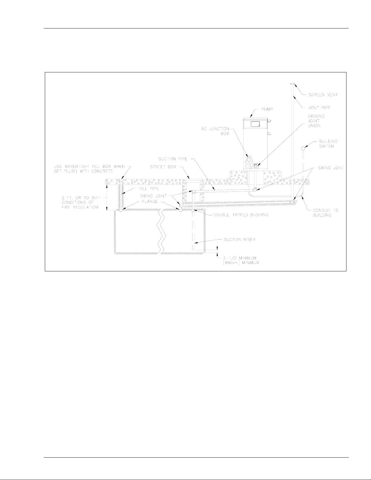
Typical Installation Layout Installation
Typical Installation Layout
Supply Line
The pump and the tank should be located close to each other (preferably within 50 feet) with
as few changes in direction of the supply line, as possible. This reduces the possibility of unit
vapor lock (gasoline only), attains the highest possible flow rate, and results in a lower
installation cost. Avoid long supply lines and excessive vertical lifts. The dynamic lift for this
unit is rated at 12 feet (3.66 m) for gasoline and 13 feet (3.96 m) for diesel and can vary
according to conditions of the installation and fuel temperature. To increase maximum flow
rate, attempt to keep the lift as small as possible.
Use new galvanized or fiberglass pipe. The riser should be 1-1/2-inches (38.1 mm) diameter.
Note: Fiberglass pipe is to be installed according to manufacturer’s specifications and
Note: Do not install an in-line
check valve, as the unit
already has an internal
valve.
requirements.
MDE-4766 Series 580 Installation/Operation/Parts Manual · April 2009 Page 9
Page 14

Installation Supply Line
Use a 2-inches pipe for standard flow units (excluding the riser) for runs up to 50 feet from the
tank. Use 2-1/2-inches to 3-inches for longer (excluding the riser) runs up to 75 feet. High
gallonage units should use larger pipes such as 3-inches (excluding the riser) for runs up to
50 feet. Use 3-1/2-inches to 4-inches (excluding the riser) for runs up to 75 feet.
Ensure that both the pipe and the tank are clean. Foreign matter entering the pump can cause
extensive damage. Obstructions in the supply line can create pump problems and reduced flow
rate.
Ensure that all pipe threads are properly cut and the inside reamed to remove burrs. Use
UL-listed, non hardening sealing compound suitable for the fluid being dispensed, on all joints
of the fuel handling plumbing. The sealing compound must also be resistant to Gasohol
(Ethanol and Methanol) when used with those fuels. Do not use Teflon Pipe Sealing Tape. Use
the sealing compound on male threads only; pipe compound used on female threads can be
squeezed into the supply line where it can enter the product stream and become lodged in the
pump or meter. Install swing joints or approved flexible pipes under the pump and at the tank
to avoid breaks in the supply line from settling or frost heave.
To avoid product delivery problems on suction pumps, ensure that there are no traps in the
supply line. Supply lines should go straight down beneath the pump to a point 18-inches
(45.7 cm) below the ground level and pitch at a rate of 1/8-inch (3.18 mm) per fo ot (.305 m)
from there down to the storage tank. The supply line should be as short and direct as possible
with swing joints at all turns. Support the horizontal run of pipe at 10 foot int ervals to maintain
pitch and prevent traps. Do not use wood as pipe supports. No additional check valves are
required as the suction pump contains an inlet check valve.
Note: After completion of installation, all liquid-carrying lines must be checked for leaks.
Page 10 MDE-4766 Series 580 Installation/Operation/Parts Manual · April 2009
Page 15

Dimensions Installation
Dimensions
MDE-4766 Series 580 Installation/Operation/Parts Manual · April 2009 Page 11
Page 16

Installation Base Layout
Base Layout
Page 12 MDE-4766 Series 580 Installation/Operation/Parts Manual · April 2009
Page 17

Wiring Precautions Wiring
4 – Wiring
Wiring Precautions
Note: Customers and installers having any questions pertaining to the installation should
contact their Gasboy distributor.
The quality of the electrical installation is a major factor in maintaining proper safety levels
and providing trouble-free operation of your pump. To assure a quality installation, follow
these rules:
1 All wiring must be installed to conform with all building/fire codes, all Federal, State, and
Local codes, National Electrical Code, (NFPA 70), NFPA 30, and Automotive and Marine
Service Station Code (NFPA 30A) codes and regulations. Canadian users must also comply
with the Canadian Electrical Code.
2 Use only threaded, rigid, metal conduit.
3 Use only UL-approved insulated gasoline and oil-resistant stranded copper wiring of the
proper size.
4 W ire connections should be tightly spliced and secured with a wire nut; close off the open end
of the wire nut with electrical tape.
5 The line to the motor should be on a separate circuit and installed on a 20 to 30 AMP breaker
depending on the motor size and/or the voltage setting.
6 Install an emergency power cutoff . In addition to circuit breaker requirements of NFPA 70 and
NFPA 30A, a single control which simultaneously removes AC power from all site dispensing
equipment is recommended. This control must be readily accessible, clearly labeled, and in
accordance with all local codes.
WARNING
To reduce the risk of electrical shock when servicing, turn off and lock out all power to the
pump, including the motor.
7 Qualified electricians who are familiar with installation of this type of equipment must
perform the installation of the pump.
MDE-4766 Series 580 Installation/Operation/Parts Manual · April 2009 Page 13
Page 18

Wiring Grounding
Grounding
T o ensure proper operation of the equipment and provide the necessary safety factors, this unit
must be grounded. A ground wire (green or green with yellow stripe) must be connected
between the unit’s AC junction box ground lug and the main electrical service panel. One (1)
earth ground connection is required per unit. The ground rod is to be a solid, corrosionresistant conductor and must be installed on the main electrical panel in accordance with the
National Electrical Code. It should be properly tied into the ground bus strip of the panel. We
recommend the neutral and ground bus strips be bonded together (unless prohibited by local
codes).
Circuit Breakers
Power to the unit must be supplied from a dedicated breaker. No other equipment should be
powered from this breaker. A tag on the motor identifies the maximum current draw of the
motor. If t wo units are supplied from one b reaker , that breaker must be capable of handling the
load of both motors.
Pump Motor
Pumps are shipped from the factory with motors wired according to the specifications given
on the order regarding kind of current, frequency and voltage.
Very often on installation, it becomes necessary to change the original setting to suit the AC
power source. To do this, locate the motor change-over plate (typically located on the shaft
end of the motor) and remove the screw which secures it in place. Slide the plate so that the
desired voltage, as marked on the plate, lines up with the screw hole. Reinsert the screw and
secure the plate in place. 380 VAC pumps are permanently set and cannot be changed.
Many motor failures result from improper setting of the motor change-over plate. If set for
120 VAC and a 240 VAC feed is used, the motor will burn out after running only for a short
time. If set for 240 VAC and a 120 VAC feed is used, the motor will run very slowly and the
starting field will soon burn out.
Models 115 V/60 Hz Units 230 V/60 Hz Units 230 V/50 Hz Units 380 V/50 Hz Units
582 6.8 3.4 4.0 N/A
583 10.6 5.3 6.3 1.5
Note: These numbers do not account for the higher level upon startup.
Motor Amp Ratings
Page 14 MDE-4766 Series 580 Installation/Operation/Parts Manual · April 2009
Page 19

Pulsers and Pulser Wiring Wiring
Pulsers and Pulser Wiring
A pulser is an optional device which is used when external monitoring of the dispensing unit
operation is desired. The pulser transmits one electrical signal (pulse) for each predetermined
amount of fuel dispensed. The signal is received by the external monitor (fuel management
system) which keeps a running total of the quantity of fuel being dispensed during each
transaction.
All Series 580 pulsers are operated with DC voltages. These are reed pulsers which are
available as either 1:1 or 10:1 pulses per unit of measure. The pulser type should be selected
according to the monitoring equipment, the application, and the regulations that must be met.
All Series 580 pulsers are mechanically driven by the register. The shaft which drives the
pulser does not turn during reset.
Conduit
Use threaded, rigid metal conduit or a rigid non-metallic conduit for applications below the
Gasboy Series 580 dispensing unit, to carry electrical wires. If you use non-metallic conduit, it
must be at least 2 feet underground. The last 2 feet of the underground run to the ground
interface must be a rigid metal conduit or threaded steel intermediate metal conduit. Tighten
all threaded conduits. When the Series 580 dispensing unit is used with a Gasboy Fuel
Management System, it is recommended that AC power wires be installed in a separate
conduit from the DC pulser; they should not run in any sort of common conduit or trough.
However, if AC and DC power wires share conduit, pulser wiring must use the cable as
specified in the Pulsers section.
When using a fuel management system other than a Gasboy system, see the manufacturer’s
installation manual for specific conduit requirements.
All wiring and conduit runs must also conform with the National Electrical Code (NFPA 70)
and the Automotive and Marine Service Station Code (NFPA 30A). All wiring and conduit
runs must conform to local codes. Canadian users must also comply with the Canadian
Electrical Code.
MDE-4766 Series 580 Installation/Operation/Parts Manual · April 2009 Page 15
Page 20

Wiring Conduit
Use the charts below as a guideline to determine the proper conduit sizes. When planning the
orientation of the wiring runs, follow the applicable Gasboy wiring diagram and consider the
layout of the components at the site. Long runs or a large number of bends may require you to
increase conduit size over what is listed, to aid in pulling wires through the conduit.
To determine conduit size needed, use the THHN/THWN Wire Areas table (left) to find the
area for each wire gauge. Add up all wire areas. Use the Areas of Trade Size Conduit Table
(right) to select the smallest number in the 25% fill area (based on NEC 501-1) that comes
closest without exceeding the total wire area.
Notes:1) Pulling of spare wires is highly recommended should wire damage occur at a later
date.
2) All wiring and conduit runs must conform with all building/fire codes, all Federal,
State, and Local codes, National Electrical Code, (NFPA 70), NFPA 30, and
Automotive and Marine Service Station Code (NFPA 30A) codes and regulations.
3) Some motors contain a brown wire (Switch Detect) which is capped at the factory.
When used, it connects to a solenoid valve or fuel management system. Do not connect
this wire without first checking the ON voltage of this line to ascertain compatibility
with the equipment being connected.
4) All wiring must be installed according to the requirements outlined in this section.
Page 16 MDE-4766 Series 580 Installation/Operation/Parts Manual · April 2009
Page 21

Wiring Diagram Wiring
C
e
otor
230
Sing
oto
380
C
T
ase
otor
Wiring Diagram
115 VAC Wiring
115 VA
Single Phas
M
230 VAC Wiring
M
VAC
le Phase
r
380 VAC Wiring
VA
hree Ph
M
Pulser Wiring
Note: This diagram is for domestic (U.S.) installations. For Canada
and other locations refer to local requirements for circuit
breaker wiring.
MDE-4766 Series 580 Installation/Operation/Parts Manual · April 2009 Page 17
Page 22

Wiring Wiring Diagram
This page is intentionally left blank.
Page 18 MDE-4766 Series 580 Installation/Operation/Parts Manual · April 2009
Page 23

Pre-startup Checklist Startup and Operation
5 – Startup and Operation
Pre-startup Checklist
The information below should be reviewed to help verify the proper installation of your
Gasboy pump. If the installation does not meet criteria listed, as well as any Federal, State, and
Local codes and requirements, correct the problem before powering on the unit.
1 The unit must be properly secured.
2 All plumbing must be complete and tight. All below ground piping must be checked for leaks.
All liquid carrying lines must be checked for leaks.
3 When DC pulsers are used in the pump, the AC and DC wires must not share any conduits,
junction boxes, or troughs.
4 All conduit work must be complete. All junction box covers must be secured with all
fasteners. Conduit seals should not be sealed until the wiring is verified through proper
operation.
5 The unit must be properly grounded.
6 Before any testing begins, remove any water in the tank through a fill opening, using a suitable
pump. Do not use the Gasboy pump to remove water. Serious damage may occur.
7 A sufficient volume of fuel must be present in the tank to ensure that the liquid level is above
the bottom of the suction pipe.
Startup and Pump Operation
Note: In order to provide the highest level of safety to you, your employees, and customers, it
is recommended that all employees be trained r ega rding the location and procedure for
turning off power to the entire system.
After successfully verifying the installation against the pre-startup checklist, the unit is ready
for startup. Follow the procedure listed below to perform an orderly start-up.
1 Turn on the circuit breaker for the pump.
2 Remove the nozzle from the boot.
3 On the right side panel, pull out the switch rod and knob assembly. This will turn on the motor
and activate the pump.
MDE-4766 Series 580 Installation/Operation/Parts Manual · April 2009 Page 19
Page 24

Startup and Operation Post Startup Tests
4 Push the reset button to zero the register.
5 Dispense fuel. Check all plumbing for leaks at this time.
6 Push the switch rod and knob assembly in to shut off the pump motor. Open the nozzle. No
fuel should be dispensed. The amount delivered should be displayed on the register. If an
optional pulser kit is attached, it will be supplying pulses which may be recorded by an
external monitoring system. Verify if the external monitoring system is reading properly.
7 Repeat steps 3 through 6 several times to ensure that the pump is operating satisfactorily.
Post Startup Tests
Voltage
The incoming voltage to the pump should be checked and any reading not within 10% of rated
voltage should be corrected before testing is continued. When dealing with suction pumps, it is
a good practice to note down voltage readings while the suction pump is operating on bypass
(turned on but not dispensing product) and also while making a delivery. Any voltage drop in
excess of 10% during either of these operating states should be considered a low voltage
condition. Corrective action should be taken to ensure adequate power supply to the pump.
Tightness
After determining that the pump is operating satisfactorily and the system is fully primed,
check the pump and piping to make sure that all connections are tight.
Meter Calibration
The 580 Series Pump is adjusted for accurate measure of the specified fuel (gasoline or diesel)
within +.05 gallons at the factory. However, since the conditions of the installation can affect
pump accuracy, it is the responsibility of the installer to check the pump for accuracy and
make any needed adjustments.
Choose the flow rate at which the meter will be used most often for the zero calibration point.
For example, if the pump is being used with an automatic nozzle, calibrate with the nozzle set
on the middle or top notch position, whichever is used most frequently.
Use a certified seraphin can to conduct the test. Fill and drain the test measure to completely
wet the interior surfaces. Reset the register to zero and deliver an exact amount into the test
can at the selected flow. Read the level of the liquid in the sight glass on the scale in + cubic
inches.
The calibration adjustment screw is located on the underside of the meter just behind and to
the left of the meter inlet. Using a flat-blade screwdriver , turn the adjusting screw clockwise to
correct for plus cubic inches or counterclockwise for minus cubic inches in the test measure.
Count the number of full turns and fractional turns each time for reference in judging the
number and direction of any additional turns required to calibrate the meter to exact zero.
Page 20 MDE-4766 Series 580 Installation/Operation/Parts Manual · April 2009
Page 25

Reconfiguration of Pump Pulley for Hand Crank Operation Startup and Operation
Strainer Cleaning
Clean the strainer immediately after the pump has been installed and tested, and again after a
few hundred gallons have been delivered. Thereafter, once every six months, or as required.
The procedure for cleaning the strainer can be found in the Maintenance and Troubleshooting
section.
Belt
Since belts do stretch slightly during the first few minutes of operation, check the belt tension
after completing the operational test. See the Maintenance and Troubl esho oti ng section for
details.
Reconfiguration of Pump Pulley for Hand Crank Operation
1
2
3
4
Before a hand crank can be used to pump fuel, you must reconfigure the pump pulley as
follows:
1 Unscrew and remove the screw (4), lock washer (3), washer (2), and pump pulley (1).
2 Flip the pump pulley (1) around so the shorter groove at the back is exposed at the front end.
3 Replace the pump pulley (1), washer (2), lock washer (3), and screw (4) and tighten the screw.
4 Engage the hand crank belt to the shorter groove.
MDE-4766 Series 580 Installation/Operation/Parts Manual · April 2009 Page 21
Page 26

Startup and Operation Reconfig ur ation of Pump Pulley for Hand Crank Operation
This page is intentionally left blank.
Page 22 MDE-4766 Series 580 Installation/Operation/Parts Manual · April 2009
Page 27

When Your Pump Needs Service Maintenance and Troubleshooting
6 – Maintenance and Troubleshooting
When Your Pump Needs Service
When your pump needs service, follow these guidelines:
• Procedures requiring disassembly of portions of the pump should be performed by
competent service personnel. Gasboy has a distributor network which services fuel
dispensing equipment in every part of the country.
• Turn off all power to the pump to reduce the risk of electrical shock when servicing
(including changing of fuel filters or strainers). Also block islands so that no vehicles can
pull up to the pump when it is being worked on.
• Replace worn, rusted, or corroded parts immediately with new authorized service parts
supplied by Gasboy. Replacing parts with incorrect or substandard substitutes will result
in unsatisfactory pump operation. Always use new gaskets or seals when servicing or
rebuilding Gasboy equipment; do not re-use old ones. Using authorized parts will ensure
the continuity of the Underwriters’ Label on your pump.
“Parts List” on page 29 lists parts and service procedures for the 580 Series. Using part
numbers when ordering will expedite your order and reduce the possibility of the wrong
parts being shipped.
The remainder of this section contains troubleshooting information and assembly/disassembly
procedures for various components that may need service.
Maintaining Trouble-free Operation
• Operate with Reasonable Care: Like any machine, the pump or remote dispenser that is
operated with reasonable care will last longer and give better service. Abuse should be
avoided (such as dropping the nozzle on the ground, operating the unit with a dirty
strainer, dragging the hose across the concrete island or driveway, running the pump with
the nozzle closed for more than two minutes and so on). The time and care given to your
pumps will be returned to you in the form of dependable service.
• Remove Water from Tank: After every fill-up, check your tanks for water. Water can
accumulate in both underground and above ground storage tanks due to condensation or
defective fill openings that are not properly protected with watertight covers. Remove any
water with a sump pump to forestall serious damage to equipment. Water, sediment, and
other foreign matter that accumulates in the tank can be drawn up into the pump and cause
failures.
• Clean the Dial Face: Use a soft, clean, damp cloth as needed.
MDE-4766 Series 580 Installation/Operation/Parts Manual · April 2009 Page 23
Page 28

Maintenance and Troubleshooting Maintaining Trouble-free Operation
• Filter: If the unit is equipped with a filter, check and change it at regular intervals. A dirty
filter in a pump or remote dispenser will cause a slower delivery rate. Refer to the
accessories section of your parts manual to ensure that you replace the filter with one
designed for your model. Always use a drip pan directly below the filter when removing
the cartridge to prevent contamination of both the soil and the electrical components
within the cabinet.
• Clean the Strainer: Clean the strainer immediately after the pump has been installed and
tested, and again after a few hundred gallons have been delivered. Thereafter, once every
six months, or as required. The symptoms of a dirty or clogged strainer in a pump are slow
delivery, noisy operation, and pulsation.
Note: This procedure should be performed only by an authorized Gasboy distributor or
installer.
To clean the strainer, proceed as follows:
1 Turn off and lock out AC power to the pump.
2 Unthread the drain plug located near the bottom of the strainer (marked “Filter”) cap. Ensure
that you use a container of sufficient capacity to catch the fuel as it drains from the pump.
3 Loosen the four bolts that hold the cap in place.
4 Carefully remove this cap which holds the spring, strainer, and inlet check valve assembly in
place.
5 Use compressed air to blow the dirt from the strainer. Always wear protective safety goggles
or glasses when using compressed air.
6 Replace the inlet check valve, strainer , and spring and reinstall the strainer cap. Ensure that the
O-Ring that seals the cap is installed properly before tightening the bolts.
7 Reinstall the drain plug using sealing compound approved for this application.
• Lubrication: Lubricate the start/stop linkage. Apply one drop of oil (SAE10) at each
pivot point of the start/stop linkage every six months.
• Adjusting the Belts (Suction Pumps Only): With proper care, belts will give
exceptionally good service. A loose belt not only cuts down dispensing speed due to
slipping, but also results in excessive wear. A properly tightened belt will allow twisting
the belt 180 degrees midway between the motor and the pump pulleys. Before adjusting
any belt, turn off AC power to the pump/remote dispenser.
The belt can be tightened by loosening the hex nut which holds the idler pulley and sliding
the pulley to the side to obtain the correct belt tension of 6-3/4 lbs. + 3/4 (30N, +3.3N).
When the adjustment is complete, remember to retighten the hex nut.
• Preserve the Finish of Your Pumps: Nearly all gasoline pumps are installed outdoors
where their surfaces are subjected to the action of the weather. As a result, it is necessary
to give the finish a reasonable amount of care if an attractive appearance is to be
maintained.
Page 24 MDE-4766 Series 580 Installation/Operation/Parts Manual · April 2009
Page 29

Troubleshooting Maintenance and Troubleshooting
The finish on Gasboy pump housings is a high-heat baked synthetic enamel, similar to that
used on automobiles. The life of this finish can be lengthened several years if, at regular
intervals, the painted surfaces are thoroughly cleaned with a high grade automobile polish
and then protected with a coat of paste wax. Do not use abrasive cleaners or polish. Do not
use high pressure spraying equipment.
In order to retain the unmarked finish on stainless steel, occasional cleaning is required. In
corrosive atmospheres, such as coastal areas, a more frequent cleaning schedule is
necessary. Under ordinary conditions, washing with deter gent or soap and water, followed
by a clean water rinse, is sufficient. If hard water is used, the surface should be wiped dry
with a soft clean cloth to prevent the formation of water spots. Marks or spots, such as
grease, oily fingerprints and smudges which resist soap and detergents, will have to be
removed with a stronger cleaner. (DO NOT use ordinary steel wool as iron particles may
adhere to the surface and cause corrosion). Care should be taken in choosing a cleaner
because any cleaning compounds or powders which contain abrasives can scratch a millrolled finish. Care must be exercised in their use to run in the direction of the polishing
lines in the steel, never across them. After cleaning, an application of paste wax is
recommended to protect the surface and prolong the interval between cleaning.
Troubleshooting
If problems are encountered in operation of the pump, follow the procedures below in an
attempt to isolate the problem.
Pump Does Not Start
Is the breaker at the panel turned on?
Is there power at pump? Check at junction box. Voltage cannot be below 104 V on a
115 V pump; 204 V on a 230 V pump.
Is motor overheated (thermal switch cutoff)? Be careful, the external motor surface could
be hot enough to cause injury. Let cool and re-try.
Replace motor if above checks do not solve the problem.
!
Pump Hums but Does Not Start
Is voltage adequate? Check voltage with pump on bypass with nozzle closed. Voltage
cannot be below 104 V on a 115 V pump; 204 V on a 230 V pump.
Check pump drive shaft for free operation.
Replace motor if above checks do not solve the problem.
!
MDE-4766 Series 580 Installation/Operation/Parts Manual · April 2009 Page 25
Page 30

Maintenance and Troubleshooting Troubleshooting
Pump Runs but Does Not Prime or Deliver Product
Is there fuel in the tank?
If register is recording but no product is being dispensed, you may have a supply line air
leak.
Check for an air leak on suction side of pump. Is check valve seated properly?
Reassemble and prime pump using liberal quantity of motor oil in pump cavity; if it
primes, run pump full flow and snap nozzle closed; shut off motor and check for leak on
suction side of pump above check valve. Any observed liquid leakage would indicate an
air leak when pump is running with nozzle open and would prevent priming when pump
was empty.
Is there an air leak in the suction line below check valve. Make accuracy check using 5
gal Seraphin test can. Any clock fast error (refer to “Inaccurate Delivery” on page 27) in
excess of 2-1/2% indicates an air leak in the suction line. The most common source of an
air leak in the suction line is the union - check union for alignment and tightness before
checking balance of suction line. If pump does not prime using oil, suction line is
blocked or has a severe air leak.
Pump Delivers Product but Does Not Register
Is main totalizer recording? If yes, problem is in the register assembly. Check to ensure
that the reset mechanism is working properly. Reset button should return fully to its
original position after being pressed. The reset lever (that is activated by the reset button)
should also return to its original position.
If the main totalizer is not working, the problem could be a broken/jammed measuring
chamber or a jammed pulser drive. If the unit has a pulser, check to ensure that the pulser
drive operates freely. Excessive drag exerted by this assembly will lock up the register
and totalizer.
Pump Delivery is Slow
Check for dirty strainer.
If pump has a filter, change filter.
Check for supply line restriction by testing the pump with a vacuum gauge. If vacuum is
abnormally high, there is a restriction.
Pump Loses Prime
Inspect check valve poppet and seat for clean mating surfaces.
If, after a period of non-use, a pump delivers product initially, followed by air and then
full flow, there is an air leak in the suction line.
Install pressure gauge between hose and nozzle. Operate pump at full flow. Snap nozzle
closed and turn off pump. If pressure falls to zero rapidly, replace check valve and clean
and inspect valve seat.
Page 26 MDE-4766 Series 580 Installation/Operation/Parts Manual · April 2009
Page 31

Meter Register Disassembly Maintenance and Troubleshooting
Inaccurate Delivery
Calibrate the meter (refer to “Wiring” on page 13).
A clock-fast error (more on the register than is delivered) in excess of 2.5% is due to air in the
suction line or vaporization of gasoline in the pump. Check pump for loss of prime and suction
line for air leak.
A clock-slow condition may result from: any slowing of the register or measuring chamber
due to excessive friction resistance or mechanical failure; inadvertent bypassing of the
measuring chamber. Check register for zero setback; check reset lever return to top of slot in
meter cover after setback; check for “hang-up” of number wheels in register or gears not
meshing.
Pump Delivers Product When not Turned On
In above ground storage tank, if fluid level is higher than pump, positive head pressure
may force product through pump. Install a pressure regulating valve or a solenoid valve
in the supply line to the pump.
Meter Register Disassembly
The B size measuring chamber can be removed for cleaning by taking out four meter body
screws, lifting off register assembly and removing three measuring chamber screws. After
separating and cleaning top and bottom half, reassemble, making sure baffle is seated in
grooves in top and bottom halves and through slot in measuring disc. Do not drop or sharply
strike chamber parts while handling. Rotate disc to make sure it turns freely and replace in
meter body. Do not overtighten screws. A torque of 20-25 ft-lbs is sufficient. When
reassembling register to meter body, use a new O-Ring.
4860 4 - Wheel Register Service
Note: Numbers in parentheses correspond to the numbers shown on the parts illustration and
parts list in
Replacing the Bearing and Seal Assembly
To replace the bearing and shaft seal assembly, or service the gear train on back of register
housing, remove housing from meter by taking out four screws.
Note: The meter housing will be full of liquid so some means should be available to catch
what drains from the case and lines.
“Parts List” on page 29 labeled 4860 4 - Wheel Register.
To remove gears, remove three retaining rings and drive key. Withdraw the drive shaft and
gear, spacer, and all parts of bearing and seal assembly. Remove the nylon washer from item
26 and note its location. Remove both oilite bearings and both
O-Rings from bore in register housing. Using new parts, which consist of a new nylon washer,
two oilite bearings, and two O-Rings, reassembly parts in reverse order. Ensure that you
lubricate both O-Rings with an O-Ring lubricant before assembling.
Reassemble gear train in following sequence: gear, key, cluster gear, retaining ring, control
block, and retaining ring.
MDE-4766 Series 580 Installation/Operation/Parts Manual · April 2009 Page 27
Page 32

Maintenance and Troubleshooting Meter Register Disassembly
This page is intentionally left blank.
Page 28 MDE-4766 Series 580 Installation/Operation/Parts Manual · April 2009
Page 33

General Parts List
7 – Parts List
General
This section lists parts information for the Gasboy 580 Series pumps. Using part numbers
when ordering will expedite your order and reduce the possibility of the wrong parts being
shipped.
Procedures requiring disassembly of portions of the pump should be performed by competent
service personnel. Do not depend upon the repair service of a general mechanic unless he is
thoroughly familiar with the mechanism. Gasboy has a distributor network which services fuel
dispensing and management systems in every part of the country.
WARNING
To reduce the risk of electrical shock when servicing, turn off and lock out all power to the
pump. Always turn off and lock out all power to the pumps at the master panel before
performing maintenance or service, including the changing of any fuel filters or strainers.
Also block islands so that no vehicles can pull up to the pump while it is being worked on.
MDE-4766 Series 580 Installation/Operation/Parts Manual · April 2009 Page 29
Page 34

Parts List 582/583 Front View
582/583 Front View
See Detail “A”
9
1
2
3
4, 5
6
7
10
118
Detail “A”
Item Description Part Number
1 Cover-Top Painted (See Note) 042206
Cover-Top SS 042207
2 Bezel-580 (also specify standard Gasboy silk-screen, below) 012328
Silk-screen, Standard *029703
3 Dial Glass-580 028650
4 Grommet, 1-inch 028960
5 Discharge Elbow, 1-inch 024895
6 Reducer Bushing, 1 x ¾, 582 Only 017278
7 Door-Front-Painted, 580 (See Note) 024581
Door-Front-SS, 580 024852
8 Panel-Side Right Painted (See Note) 041386
Panel-Side Right SS 041393
9 Panel-Side Left Painted, 580 (See Note) 041385
Panel-Side Left SS, 580 041391
Page 30 MDE-4766 Series 580 Installation/Operation/Parts Manual · April 2009
Page 35

582/583 Side View Parts List
Item Description Part Number
10 Plate 045804
11 Grommet 058021
Note: Painted standard Gasboy colors unless otherwise specified. Refer to
“Introduction” on page 1 for details on standard colors.
582/583 Side View
1
2, 7
3
4, 5
6
Item Description Part Number
1 Hook Hose 003740
2 Boot Nozzle 003338
3 Panel Rear Painted, 580 (See Note) 030847
Panel Rear SS, 580 041394
4 Switch Rod and Knob Assembly 033007
5 Bushing, Switch Rod 017123
MDE-4766 Series 580 Installation/Operation/Parts Manual · April 2009 Page 31
Page 36

Parts List 582/583 Chassis
Item Description Part Number
6 Hook-Nozzle Mach. 003700
7 Gasket-Nozzle Boot 026850
Note: Painted standard Gasboy colors unless otherwise specified. Refer to
“Introduction” on page 1 for details on standard colors.
582/583 Chassis
1
10
8
2, 3
4
5 See Detail “A”
6
7
8
13
12
Detail “A”
11
11
9
14
Page 32 MDE-4766 Series 580 Installation/Operation/Parts Manual · April 2009
Page 37

582/583 Chassis Parts List
Part
Item Description
1 Pulser Assembly, CX (See Breakdown for parts) 023062
2 Meter Register, Gallon with Pulser 036326
Meter Register, Liter with Pulser 036327
Meter Register, Gallons 036328
Meter Register, Liters 036329
Meter Register, Liters 029706
3 Dial Mask (Must specify liters {029702}, Liters
{029704}, Liters {029706}, Gallons {029705}, or
Gallons {029708})
4 Plate 023869
5 Discharge Assembly 023088
6 Motor Assembly (See breakdown for your model) 7 Pump Assembly (See breakdown for your model) 023083
8 Column Brace 015797
9 Base 011902
10 Pipe Assembly (See breakdown for your model) 11 Gasket 027055
12 Spacer Plate, Meter Register 023077
13 Elbow Flange 003560
14 Discharge Pipe 044016
Number
035217
MDE-4766 Series 580 Installation/Operation/Parts Manual · April 2009 Page 33
Page 38

Parts List 582/583 Motor
582/583 Motor
See Detail “A”
1
15
18
16, 3
3
17
4, 532
6
7, 8
10
11
10
12
13, 14
Detail “A”
22
21
Item Description Part Number
1 Bracket-Motor Support 023072
2 Motor, Franklin, 3/4HP, DF, CW, 61FR, Model 583 only F37609
Motor, Franklin, 3/4HP, 61FR, Model 583, 380 V option only F37320
Motor, Franklin, 1/2HP, DVDF, CW, 61FR, Model 582 only F37630
3 Cotter Pin, 1/16 x 1/2 042430
4 Pulley, 5/8 Bore, 2-3/4, 583 50 Hz 047006
Pulley, 5/8 Bore, 2.4, 583 60 Hz 047005
Pulley, 5/8 Bore, 1-3/4, 582 60 Hz 047203
Pulley, 5/8 Bore, 2.0, 582 50 Hz 047204
5 Key 031315
19
Page 34 MDE-4766 Series 580 Installation/Operation/Parts Manual · April 2009
Page 39

582/583 Motor Parts List
Item Description Part Number
6 Conduit, Motor to J-Box 023075
7 Rod-Motor Bracket 023093
8 Cotter Pin, 3/32 x 3/4 042355
9 Pulley-Idler 047009
10 Belt, 4L400-A38, 583 012121
Belt, Tri-Power, V-AX37, 582 012133
11 1/2-inch UNY Explosion Proof Conduit Union 066400
12 Bracket, Junction Box 023074
13 Junction Box Machining 003337
14 Junction Box Cover, Machining 003461
15 Bracket-Motor Support 015458
16 Pin-Rod End 042145
17 Rod End 050250
18 Rod-Switch Handle 051209
19 Bracket, Support 017001
20 Switch Arm 017002
21 Rod Switch 023096
MDE-4766 Series 580 Installation/Operation/Parts Manual · April 2009 Page 35
Page 40

Parts List 582/583 Pump
582/583 Pump
7
3
12, 13
9
1
6
8
14
5
10 15
Item Description Part Number
1 Pumping Unit M04920B003
2 Union, 1-1/2-inches K12179
3 Fitting, E1, 3/8 Flare X 1/4 NPTM 026038
4 Pump Support Plate 023071
5 Inlet Adapter 023146
6 O-Ring, 2.237 X 0.103 Q10067-31
7 Tube Air Vent M08687B001
8 Screw, Tap 1/4-20 X 5/8 Long K85736-39
9 Screw, M6 X 20 M04973B001
10 Bolt, M8 X 1-25 X 20 mm Q11106-06
11 Nipple, 1 1/2 X 1-3/4 Long R11493-77
12 Outlet Flange 023092
13 O-Ring 1-1/8 X 1-3/8 X 1/8 Q10068-07
14 Motor Support Bracket 014565
15 Screw, M10 X 20 Long M04973B004
16 Gasket, Seal Suction 054190
11
4
2, 16
View A - A
Page 36 MDE-4766 Series 580 Installation/Operation/Parts Manual · April 2009
Page 41

Pumping Unit Breakdown Parts List
Pumping Unit Breakdown
MDE-4766 Series 580 Installation/Operation/Parts Manual · April 2009 Page 37
Page 42

Parts List Pumping Unit Breakdown
Model M04920B003 - Pumping Unit Parts List
Notes:1) Parts listed in the following table are not available for individual purchase. Repair
kits may be purchased. Refer to “Accessories and Field Kits” on page 43.
2) Refer to “Adjustable Bypass Parts Breakdown” on page 39 for additional parts and
graphics.
Item Part Description Quantity Item Part Description Quantity
1 Body (non-reverse float) 1 31 Seal, Lip (with plug) 1
Body (reverse float) 1 32 Seal, Retainer 1
2 Blade, Rotor 6 33 Seal, Square 1
3 Clamp (refer to note 1) 1 34 Rotor and Shaft Assembly 1
4 Connector, Male 1 19 Key 1
5 Cover, Atmos. Chamber 1 35 Ring, Retaining 1
6 Cover, Bypass Valve 1 36 Screw (refer to no te 1) 1
7 Cover, Control Valve 1 37 Screw, M8 1.25x15 mm 1
8 Cover, Filter 1 38 Screw, M8 1.25x20 mm (refer to note 1) 9 Float, Non-Reversing 1 39 Screw, M8 1.25x25 mm 24
11 Gasket, Atmos. Cham. Cover 1 40 Screw, M6 1x20 mm 6
12 Gasket, Bypass Valve 1 41 Separator & Air Eliminator 1
13 Gasket, Clamping Ring 1 42 Sleeve, Tube (refer to note 1) 1
14 Gasket, Control Valve Cover 1 43 Spring, Control Valve (H.D.) 1
15 Gasket, Filter Cover 1 44 Spring, Filter 1
16 Gasket, Inlet (Separator) 1 45 Stator, H.D. 1
17 Gasket, Outlet (Separator) 1 46 Stop, Filter Insert 1
18 Insert 1 47 Strainer Assembly-149 micron 1
19 Key 1 Strainer, 70 Micron 1
20 Nut, Tube (refer to note 1) 1 Paper Filter (not shown) 1
21 Nut 1 48 Tube, Vent Assy- 9024 (refer to note 1) 2
22 O-ring 1 Tube, Vent Assy- 9033 & 9036 3
23 Plug, Pipe 1/4-inch 2 Tube, Vent Assy- 9044 & 9048 4
24 Pulley 1 49 Valve Assembly, Bypass 1
25 Ring, Throw Out (H.D.) 2 50 Valve Assembly, Control 1
26 Ring, Clamping 1 51 Valve, Relief 30-50 psi 1
27 Ring, Retaining 1 52 Valve Assembly, Float 1
28 Rotor Support Assembly 1 53 Washer 1
29 Cover, Rotor 1 54 Washer (refer to note 1) 2
30 Screw, M3.5 Flat Hd 3 55 Washer, Lock 1
Notes:
1. Not part of the pumping unit.
2. Current pumping unit use a 10-blade assembly. If you have a 6-blade rotor assembly, you can replace blades, but the
replacement rotor assembly uses a 10-blade design. When you need to replace the blades, it ia also recommended that you
replace 6-blade rotor assemblies with a 10-blade rotor assembly for quieter operation and better performance.
Page 38 MDE-4766 Series 580 Installation/Operation/Parts Manual · April 2009
Page 43

582/583 Piping Parts List
Adjustable Bypass Parts Breakdown
60
61
Item Part Description
58 Nut
59 Screw - Adjustable
60 Cover
61 Gasket - screw
582/583 Piping
58
2
5
59
1
3
8, 10
5
1
2
3
4
4
9
023070 Pipe 023079 Pipe W/Filter Assembly
6
7
MDE-4766 Series 580 Installation/Operation/Parts Manual · April 2009 Page 39
Page 44

Parts List 582/583 Piping
023070 Pipe Assembly
Item Description Part Number
1 Gasket-Inlet/Outlet 027055
2 Flange-Meter Inlet 015496
3 Flange Plate-Meter Inlet 015495
4 Piping-Pump Outlet 015497
5 O-Ring 023091
023079 Pipe W/Filter Assembly
Item Description Part Number
1 Gasket-Inlet/Outlet 027055
2 Flange, 1-inch 003650
3 Pipe TBE, 1 x 3 044525
4 Elbow, 1-inch x 90 024895
5 Pipe TOE, 1 x 4 045235
6 Adapter, 1-inch Cimtek 400
Filter
7 Coupling Nipple, 4-3/4 015498
8 Elbow, Dresser 1 x 90 024910
9 Pipe TOE, 1 x 2-1/2 045218
10 Dresser Elbow Seal, 1-inch 054207
003087
Page 40 MDE-4766 Series 580 Installation/Operation/Parts Manual · April 2009
Page 45

582/583 Pulser Parts List
582/583 Pulser
2
3
4
5
1
6
1
10, 9
7
8
Item Description Part Number
1 Cotter Pin, 3/64 x 1/2 042290
2 Elbow-Conduit, ½ x 90 M/F 025045
3 Cable Assembly, Pulser Drive 023089
4 Pulser, 10:1, VR 021788
5 Bracket-Pulser 015919
6 Conduit, J-Box Pulser 014031
7 1/2-inch UNY Explosion Proof Conduit Union 066400
8 Bracket, Junction Box 023074
9 J-Box Machining 003340
10 J-Box Cover Machining 003515
MDE-4766 Series 580 Installation/Operation/Parts Manual · April 2009 Page 41
Page 46

Parts List Hand Crank Assembly
Hand Crank Assembly
17
2
1
9
21
13
This view shown
without pulley
bracket
To Pumping Unit
Item Description Part Number
1 Screw, 5/16-18 x 1/2 Hex Washer 053910
2 Bearing-Pltd Assembly 030803
3 Housing/Bearing Assembly 030024
4 Shaft, Drive 055007
5 Pulley, 5-1/4 x 3/4-inch bore 047015
6 Screw, 1/4-20 x 5/8 Sq. Head Set
Cad Case Hardened
7 Bushing, Hand Crank 017130
8 Bracket, Pulley 014864
9 Belt, 4L230, A21 012166
10 Screw, 5/16-18-3/4 HHC Pl 051895
11 Washer, Std. Spring Lock, 5/16 068875
12 Washer, 5/16-18 x 1/2 068080
13 Belt, 4L460-A44 012177
14 Pulley, 2-inch x 5-inch Bore 048709
15 Screw, Set 5/16-18 x 1/2 052010
16 Shaft, Drive 055005
17 Hand Crank Assembly 023139
Front
1
1
Rear
8
053731
5
1
5
2
Detail “B”
3
5
4
7
16
5
5
See Detail “B”
15
3
14
5
6
7
8
9
10, 11,
7
5
13
Page 42 MDE-4766 Series 580 Installation/Operation/Parts Manual · April 2009
Page 47

Accessories and Field Kits Parts List
Item Description Part Number
18 Washer, .505ID x .880OD, .058T 068040
19 Retaining Ring, .396 Diameter 049403
20 Pin, Roll, 3/16 x 1 043030
Note: Refer to “Reconfiguration of Pump Pulley for Hand Crank Operation” on page 21.
Accessories and Field Kits
External Low Flow Filter Kits
Typically used on Model 582. Components are not designed for use with Methanol or
Methanol blends.
Kit Number Kit Description
032115 External Standard Speed Filter Kit (includes adapter, standard speed particulate filter
032116 External Standard Speed Hydrosorb Filter Kit (includes adapter, standard speed Hydrosorb
element and pipe fittings)
filter element and pipe fittings)
External High Flow Filter Kits
Typically used on Model 583. Components are not designed for use with Methanol or
Methanol blends.
Kit Number Kit Description
032754 External Single Element High Flow Kit (includes adapter, one high flow particulate filter
element and pipe fittings)
032755 External Single Element High Flow Hydrosorb Kit (includes adapter, one high flow
Hydrosorb filter element and pipe fittings)
Replacement Elements (For both 582 and 583 Models)
Kit Number Kit Description
026018 Standard (removes particulates only)
026019 Hydrosorb (removes water and particulates)
Pulser Kit
Kit Number Kit Description
023131 10:1 Pulser Kit
MDE-4766 Series 580 Installation/Operation/Parts Manual · April 2009 Page 43
Page 48

Parts List Accessories and Field Kits
Pumping Unit Kits
Kit Number Kit Description
M04920K100 Bypass Valve
M04920K101 Strainer
M04920K102 Master Steel
M04920K104 Control Valve
M04920K105 Lip Seal
M04920K109 Inlet Check Valve
M04920K116 Blades
M04920K117 Pumping Element Field Rebuild
M04920K118 Pumping Element Shop Rebuild
Page 44 MDE-4766 Series 580 Installation/Operation/Parts Manual · April 2009
Page 49

Index
Index
Numerics
003087 40
003337 35
003338 31
003340 41
003461 35
003515 41
003560 33
003650 40
003700 32
003740 31
011902 33
012121 35
012133 35
012166 42
012177 42
012328 30
014031 41
014565 36
014864 42
015458 35
015495 40
015496 40
015497 40
015498 40
015797 33
015919 41
017001 35
017002 35
017123 31
017130 42
017278 30
021788 41
023062 33
023071 36
023072 34
023074 35, 41
023075 35
023077 33
023083 33
023088 33
023089 41
023091 40
023092 36
023093 35
023096 35
023131 43
023139 42
023146 36
023869 33
024581 30
024852 30
024895 30, 40
024910 40
025045 41
026018 43
026019 43
026038 36
026850 32
027055 33, 40
028650 30
029703 30
029706 33
030024 42
030803 42
030847 31
031315 34
032115 43
032116 43
032754 43
032755 43
033007 31
035217 33
036326 33
036327 33
036328 33
036329 33
041385 30
041386 30
041391 30
041393 30
041394 31
042145 35
042206 30
042207 30
042290 41
042355 35
042430 34
043030 43
044016 33
044525 40
045218 40
045235 40
045804 31
047005 34
047006 34
047009 35
047015 42
047203 34
047204 34
048709 42
049403 43
050250 35
051209 35
051895 42
052010 42
053731 42
053910 42
054190 36
054207 40
055005 42
055007 42
058021 31
066400 35, 41
068040 43
068080 42
068875 42
A
Alert symbol 3
B
Barricading 3
C
Caution warnings 3
D
Danger warnings 3
E
Electrical
Shut-off 3
Emergency
Electrical shut-off 3
In Case Of 5
Personnel (contacting) 4
Evacuation 3
Explosions
Preventing 3
F
F37320 34
F37609 34
F37630 34
Fires
Preventing 3
K
K12179 36
K85736-39 36
MDE-4766 Series 580 Installation/Operation/Parts Manual · April 2009 Index-1
Page 50

M
M04920B003 36
M04920K100 44
M04920K101 44
M04920K102 44
M04920K104 44
M04920K105 44
M04920K109 44
M04920K116 44
M04920K117 44
M04920K118 44
M04973B001 36
M04973B004 36
M08687B001 36
P
Personnel
Emergency (informing) 4
Q
Q10067-31 36
Q10068-07 36
Q11106-06 36
S
Safety Information 3
Alert symbol 3
Barricading 3
Emergency electrical shut-off 3
Emergency personnel 4
Evacuation 3
NFPA regulations 3
Open flames 3
Preventing explosions and fires 3
Regulations 3
Replacement parts 3
Safety symbols 3
Shut-off 3
Signal words 3
Smoking 4
Sparks 4
Warning words 3
Working alone 4
Safety symbols 3
Shut-off 3
Emergency electrical 3
Signal words
Safety 3
R
R11493-77 36
UL® is a registered trademark of Underwriters Laboratories Inc.
W
Warning words 3
Warnings 3
© 2009 GASBOY
7300 West Friendly Avenue · Post Office Box 22087
Greensboro, North Carolina 27420
Phone 1-800-444-5529 · http://www.gasboy.com · Printed in the U.S.A.
MDE-4766 Series 580 Installation/Operation/Parts Manual · April 2009
 Loading...